WO2017018306A1 - 電流センサ - Google Patents
電流センサ Download PDFInfo
- Publication number
- WO2017018306A1 WO2017018306A1 PCT/JP2016/071347 JP2016071347W WO2017018306A1 WO 2017018306 A1 WO2017018306 A1 WO 2017018306A1 JP 2016071347 W JP2016071347 W JP 2016071347W WO 2017018306 A1 WO2017018306 A1 WO 2017018306A1
- Authority
- WO
- WIPO (PCT)
- Prior art keywords
- current sensor
- sensor unit
- flow path
- sensor element
- current
- Prior art date
Links
Images


Classifications
-
- G—PHYSICS
- G01—MEASURING; TESTING
- G01R—MEASURING ELECTRIC VARIABLES; MEASURING MAGNETIC VARIABLES
- G01R15/00—Details of measuring arrangements of the types provided for in groups G01R17/00 - G01R29/00, G01R33/00 - G01R33/26 or G01R35/00
- G01R15/14—Adaptations providing voltage or current isolation, e.g. for high-voltage or high-current networks
- G01R15/20—Adaptations providing voltage or current isolation, e.g. for high-voltage or high-current networks using galvano-magnetic devices, e.g. Hall-effect devices, i.e. measuring a magnetic field via the interaction between a current and a magnetic field, e.g. magneto resistive or Hall effect devices
-
- G—PHYSICS
- G01—MEASURING; TESTING
- G01R—MEASURING ELECTRIC VARIABLES; MEASURING MAGNETIC VARIABLES
- G01R19/00—Arrangements for measuring currents or voltages or for indicating presence or sign thereof
- G01R19/0092—Arrangements for measuring currents or voltages or for indicating presence or sign thereof measuring current only
-
- G—PHYSICS
- G01—MEASURING; TESTING
- G01R—MEASURING ELECTRIC VARIABLES; MEASURING MAGNETIC VARIABLES
- G01R33/00—Arrangements or instruments for measuring magnetic variables
- G01R33/02—Measuring direction or magnitude of magnetic fields or magnetic flux
- G01R33/06—Measuring direction or magnitude of magnetic fields or magnetic flux using galvano-magnetic devices
- G01R33/07—Hall effect devices
-
- G—PHYSICS
- G01—MEASURING; TESTING
- G01R—MEASURING ELECTRIC VARIABLES; MEASURING MAGNETIC VARIABLES
- G01R33/00—Arrangements or instruments for measuring magnetic variables
- G01R33/02—Measuring direction or magnitude of magnetic fields or magnetic flux
- G01R33/06—Measuring direction or magnitude of magnetic fields or magnetic flux using galvano-magnetic devices
- G01R33/09—Magnetoresistive devices
-
- G—PHYSICS
- G01—MEASURING; TESTING
- G01V—GEOPHYSICS; GRAVITATIONAL MEASUREMENTS; DETECTING MASSES OR OBJECTS; TAGS
- G01V3/00—Electric or magnetic prospecting or detecting; Measuring magnetic field characteristics of the earth, e.g. declination, deviation
- G01V3/08—Electric or magnetic prospecting or detecting; Measuring magnetic field characteristics of the earth, e.g. declination, deviation operating with magnetic or electric fields produced or modified by objects or geological structures or by detecting devices
- G01V3/10—Electric or magnetic prospecting or detecting; Measuring magnetic field characteristics of the earth, e.g. declination, deviation operating with magnetic or electric fields produced or modified by objects or geological structures or by detecting devices using induction coils
- G01V3/104—Electric or magnetic prospecting or detecting; Measuring magnetic field characteristics of the earth, e.g. declination, deviation operating with magnetic or electric fields produced or modified by objects or geological structures or by detecting devices using induction coils using several coupled or uncoupled coils
- G01V3/108—Electric or magnetic prospecting or detecting; Measuring magnetic field characteristics of the earth, e.g. declination, deviation operating with magnetic or electric fields produced or modified by objects or geological structures or by detecting devices using induction coils using several coupled or uncoupled coils the emitter and the receiver coils or loops being uncoupled by positioning them perpendicularly to each other
-
- G—PHYSICS
- G01—MEASURING; TESTING
- G01V—GEOPHYSICS; GRAVITATIONAL MEASUREMENTS; DETECTING MASSES OR OBJECTS; TAGS
- G01V3/00—Electric or magnetic prospecting or detecting; Measuring magnetic field characteristics of the earth, e.g. declination, deviation
- G01V3/08—Electric or magnetic prospecting or detecting; Measuring magnetic field characteristics of the earth, e.g. declination, deviation operating with magnetic or electric fields produced or modified by objects or geological structures or by detecting devices
- G01V3/10—Electric or magnetic prospecting or detecting; Measuring magnetic field characteristics of the earth, e.g. declination, deviation operating with magnetic or electric fields produced or modified by objects or geological structures or by detecting devices using induction coils
- G01V3/101—Electric or magnetic prospecting or detecting; Measuring magnetic field characteristics of the earth, e.g. declination, deviation operating with magnetic or electric fields produced or modified by objects or geological structures or by detecting devices using induction coils by measuring the impedance of the search coil; by measuring features of a resonant circuit comprising the search coil
Definitions
- the present invention relates to a current sensor, and more particularly to a current sensor that detects a value of a current to be measured by measuring a magnetic field generated according to the current to be measured.
- Patent Document 1 JP 2013-170878 A
- a plurality of current paths arranged on the same plane include a first conductor portion, a second conductor portion connected to one end of the first conductor portion, and a first conductor portion.
- a third conductor portion connected to the other end of the first conductor portion.
- An adjacent second conductor portion is disposed on an extension line extending in the length direction of the first conductor portion from one end of the first conductor portion, and on an extension line extending in the length direction of the first conductor portion from the other end of the first conductor portion.
- a pair of magnetoelectric transducers sandwiching the first conductor portion symmetrically and disposed at a position perpendicular to the plane to detect a magnetic field formed by the first conductor portion.
- each conductor portion of a plurality of current paths is bent in the same plane to change the direction of current flow, thereby detecting the magnetic field of the corresponding current path.
- the effect of the current path adjacent to the corresponding current path on the conversion element is suppressed.
- the present invention has been made in view of the above problems, and provides a small current sensor in which measurement errors are reduced by suppressing the influence of a magnetic field that circulates around a conductor adjacent to a corresponding conductor and an external magnetic field. For the purpose.
- the current sensor according to the present invention includes a first current sensor unit and a second current sensor unit.
- Each of the first current sensor unit and the second current sensor unit flows a current to be measured, includes a front surface and a back surface, and includes a length direction, a width direction orthogonal to the length direction, and the length direction and the above
- a plate-like conductor having a thickness direction orthogonal to the width direction, and a first magnetic sensor element and a second magnetic sensor element for detecting the strength of the magnetic field generated by the current are included.
- the conductor includes a first flow path portion and a second flow path portion in which the current is divided and flows in the middle in the length direction.
- the first magnetic sensor element is located inside the area as seen from the width direction
- the second magnetic sensor element is located on the back surface side of the first flow path portion, and is located inside the region and located on the front surface side of the second flow path portion when viewed from the width direction.
- the respective conductors of the first current sensor unit and the second current sensor unit are arranged in parallel with a distance from each other and extend in the length direction. Since the region of the first current sensor unit is shifted from the region of the second current sensor unit in the length direction, the first magnetic sensor element and the second magnetic sensor of the first current sensor unit. Each of the elements is located outside the region of the second current sensor unit when viewed from the width direction, and each of the first magnetic sensor element and the second magnetic sensor element of the second current sensor unit is When viewed from the width direction, the first current sensor unit is located outside the region.
- the conductors of the first current sensor unit and the second current sensor unit are aligned with each other at an interval in the width direction.
- Each of the first magnetic sensor element and the second magnetic sensor element of the first current sensor unit overlaps the conductor of the second current sensor unit when viewed from the width direction, and the first current sensor unit has a first current sensor unit.
- Each of the magnetic sensor element and the second magnetic sensor element overlaps the conductor of the first current sensor unit as viewed from the width direction.
- the conductors of the first current sensor unit and the second current sensor unit are aligned with each other at an interval in the thickness direction.
- Each of the first magnetic sensor element and the second magnetic sensor element of the first current sensor unit overlaps the conductor of the second current sensor unit when viewed from the thickness direction, and
- Each of the first magnetic sensor element and the second magnetic sensor element overlaps the conductor of the first current sensor unit when viewed from the thickness direction.
- the conductor includes an arched portion that is bent so as to protrude in one of the thickness directions and extends in the length direction, and constitutes a first flow path portion.
- the conductor further includes an inverted arch-shaped portion that is bent so as to protrude to the other side in the thickness direction and extends in the length direction, and constitutes a second flow path portion.
- the arch-shaped portion and the reverse arch-shaped portion have the same shape in each of the first current sensor unit and the second current sensor unit.
- the first flow path portion bulges to the surface side of the conductor when viewed from the width direction.
- the second flow path portion bulges to the back side of the conductor when viewed from the width direction.
- each of the first flow path portion and the second flow path portion has one end and the other end in the length direction.
- One end of the first flow path portion and the other end of the first flow path portion in the length direction are different from each other in the thickness direction.
- One end of the second flow path portion and the other end of the second flow path portion in the length direction are different from each other in the thickness direction.
- the positions in the thickness direction of the one end of the first flow path portion and the one end of the second flow path portion in the length direction are equal to each other.
- the other end of the first flow path portion and the other end of the second flow path portion in the length direction have the same position in the thickness direction.
- the first flow path part includes a bent part that connects the position of one end of the first flow path part and the position of the other end of the first flow path part in the thickness direction.
- the second flow path part includes a bent part that connects the position of one end of the second flow path part and the position of the other end of the second flow path part in the thickness direction.
- the bent part of the first flow path part and the bent part of the second flow path part are located at a distance from each other in the length direction.
- the conductor in each of the first current sensor unit and the second current sensor unit, is provided with the slit extending in the length direction, so that the first flow path unit and the second current sensor unit The two flow path portions are located at a distance from each other in the width direction.
- the slit is located at the center of the conductor in the width direction.
- the first magnetic sensor element and the second magnetic sensor element are mounted on one substrate.
- each of the first current sensor unit and the second current sensor unit calculates the value of the current by calculating the detection value of the first magnetic sensor element and the detection value of the second magnetic sensor element. And a calculation unit for calculating.
- the phase of the detection value of the first magnetic sensor element and the phase of the detection value of the second magnetic sensor element Are in reverse phase, and the calculation unit is a subtractor or a differential amplifier.
- each of the first current sensor unit and the second current sensor unit calculates the value of the current by calculating the detection value of the first magnetic sensor element and the detection value of the second magnetic sensor element. And a calculation unit for calculating.
- the phase of the detection value of the first magnetic sensor element and the phase of the detection value of the second magnetic sensor element Are in phase and the calculation unit is an adder or a summing amplifier.
- each of the first magnetic sensor element and the second magnetic sensor element has a detection axis, and the detection axis has the width described above. It is arranged to face the direction.
- Each of the first magnetic sensor element and the second magnetic sensor element is configured such that the detection sensitivity changes according to the strength of the bias magnetic field in the length direction.
- the current sensor can be reduced in size while reducing the measurement error by suppressing the influence of the magnetic field that circulates around the conductor adjacent to the corresponding conductor and the external magnetic field.
- FIG. 2 is a cross-sectional view of the current sensor according to Embodiment 1 of the present invention, as viewed from the direction of arrows VV in FIG.
- FIG. 9 is a contour map showing the result of a simulation analysis of the magnetic flux density of a magnetic field generated when a current outside the measurement target is passed through the two primary conductors of the current sensor according to the comparative example. is there. It is a graph which shows the displacement of the magnetic flux density of the X-axis direction component from the starting point on the centerline Lc of FIG. 12 to an end point.
- the same cross-sectional view as FIG. 11 shows the result of simulation analysis of the magnetic flux density of the magnetic field generated when a current outside the measurement target is passed through the two primary conductors of the current sensor according to the second embodiment of the present invention.
- FIG. 11 shows the result of simulation analysis of the magnetic flux density of the magnetic field generated when a current outside the measurement target is passed through the two primary conductors of the current sensor according to the second embodiment of the present invention.
- FIG. 20 It is a perspective view which shows the external appearance of the primary conductor with which the current sensor which concerns on Embodiment 6 of this invention is provided. It is the side view which looked at the primary conductor of FIG. 20 from the arrow XXI direction. It is the top view which looked at the primary conductor of FIG. 20 from the arrow XXII direction. It is the front view which looked at the primary conductor of FIG. 20 from arrow XXIII. It is a perspective view which shows the external appearance of the current sensor which concerns on Embodiment 7 of this invention. It is the side view which looked at the current sensor of Drawing 24 from the XXV direction.
- FIG. 1 is a perspective view showing an appearance of a current sensor according to Embodiment 1 of the present invention.
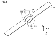
- FIG. 2 is a perspective view showing an appearance of a primary conductor included in the current sensor according to Embodiment 1 of the present invention.
- FIG. 3 is an exploded perspective view showing the configuration of the magnetic sensor unit provided in the current sensor according to Embodiment 1 of the present invention.
- FIG. 4 is a perspective view showing an appearance of a housing of the magnetic sensor unit provided in the current sensor according to the first embodiment of the present invention.
- FIG. 5 is a cross-sectional view of the current sensor according to Embodiment 1 of the present invention, as viewed from the direction of arrows VV in FIG.
- FIG. 6 is a cross-sectional view of the current sensor according to Embodiment 1 of the present invention, as viewed from the direction of arrows VI-VI in FIG.
- FIG. 7 is a circuit diagram showing a circuit configuration of the current sensor according to Embodiment 1 of the present invention.
- the width direction of primary conductors 110a and 110b which will be described later, is the X-axis direction, and the length direction of primary conductors 110a and 110b is the Y-axis direction.
- the thickness direction of 110b is illustrated as the Z-axis direction. 5 and 6, the housing 150 is not shown.
- FIG. 5 in the width direction (X-axis direction) of the primary conductors 110a and 110b, a center line passing through the center of each of the first magnetic sensor element 120a and the second magnetic sensor element 120b described later is indicated by Lc. Yes.
- FIG. 7 shows a circuit configuration of a portion corresponding to one primary conductor 110a, 110b.
- the current sensor 100 includes a first current sensor unit 100a and a second current sensor unit 100b.
- the current sensor 100 includes two current sensor units, but the number of current sensor units included in the current sensor is not limited to two and may be plural. For example, when the current sensor 100 is applied to a three-phase three-wire wiring, the current sensor 100 includes three current sensor units.
- Each of the first current sensor unit 100a and the second current sensor unit 100b includes a primary conductor 110a, 110b that is a conductor through which a current to be measured flows, and a magnetic field generated by the current to be measured through the primary conductors 110a, 110b.
- the first magnetic sensor element 120a and the second magnetic sensor element 120b are provided for detecting the strength of the first magnetic sensor element.
- the primary conductors 110a and 110b include the front surface and the back surface, the length direction (Y-axis direction), the width direction (X-axis direction) orthogonal to the length direction (Y-axis direction), and the length A plate shape having a thickness direction (Z-axis direction) orthogonal to the vertical direction (Y-axis direction) and the width direction (X-axis direction).
- the current to be measured is divided into two flow paths as will be described later, and the primary conductors 110a and 110b are indicated by arrows 1a and 1b. It flows in the length direction (Y-axis direction) of the primary conductors 110a and 110b.
- the primary conductors 110a and 110b include a first flow path portion and a second flow path portion in which a current to be measured flows in a halfway direction (Y-axis direction).
- the primary conductors 110a and 110b are bent so as to protrude in one of the thickness directions (Z-axis direction) of the primary conductors 110a and 110b and extend in the length direction (Y-axis direction).
- the arch-shaped part 111 which is the first flow path part constituting one of the flow paths, and the length direction (Y-axis direction) is bent so as to protrude to the other of the thickness direction (Z-axis direction).
- an inverted arch-shaped portion 116 that is a second flow path portion that constitutes one of the two flow paths. That is, the first flow path portion bulges to the surface side of the primary conductors 110a and 110b when viewed from the width direction (X-axis direction) of the primary conductors 110a and 110b.
- the second channel portion bulges to the back side of the primary conductors 110a and 110b when viewed from the width direction (X-axis direction) of the primary conductors 110a and 110b.
- the arch-shaped portion 111 and the reverse arch-shaped portion 116 are arranged side by side in the width direction (X-axis direction) of the primary conductors 110a and 110b, and the opening 10 is formed inside the arch-shaped portion 111 and the reverse arch-shaped portion 116.
- the opening 10 is formed as an area surrounded by the first flow path part and the second flow path part when viewed from the width direction (X-axis direction) of the primary conductors 110a and 110b.
- the arch-shaped portion 111 is spaced apart from each other by a first protrusion 112 and a second protrusion that protrude perpendicularly to the main surfaces of the primary conductors 110a and 110b. It is comprised from the part 113 and the extension part 114 extended in the length direction (Y-axis direction) of the primary conductors 110a and 110b, and connecting the 1st protrusion part 112 and the 2nd protrusion part 113.
- the shape of the arch-shaped portion 111 is not limited to this, and may be, for example, C-shaped or semicircular when viewed from the width direction (X-axis direction) of the primary conductors 110a and 110b. .
- the reverse arched portion 116 is spaced apart from each other by the third and fourth protruding portions 117 and 118 protruding perpendicularly to the main surfaces of the primary conductors 110a and 110b, and the lengths of the primary conductors 110a and 110b.
- the extending portion 119 extends in the vertical direction (Y-axis direction) and connects the third protruding portion 117 and the fourth protruding portion 118.
- the shape of the reverse arch-shaped portion 116 is not limited to this, and may be a C-shape or a semicircular shape when viewed from the width direction (X-axis direction) of the primary conductors 110a and 110b, for example. Good.
- the arched portion 111 and the reverse arched portion 116 have the same shape, but may have different shapes.
- the distance between the extending portion 114 and the extending portion 119 in the thickness direction (Z-axis direction) of the primary conductors 110a and 110b is Hb.
- the primary conductors 110a and 110b are provided with slits 115 extending in the length direction (Y-axis direction) of the primary conductors 110a and 110b.
- the slit 115 is adjacent to the arched portion 111 in the width direction (X-axis direction) of the primary conductors 110a and 110b. Note that the slit 115 is not necessarily provided.
- the slit 115 is located at the center of the primary conductors 110a and 110b in the width direction (X-axis direction) of the primary conductors 110a and 110b.
- the slit 115 is located between the arch-shaped portion 111 and the reverse arch-shaped portion 116. That is, since the slit 115 is provided, the first flow path portion and the second flow path portion are positioned at a distance from each other in the width direction (X-axis direction) of the primary conductors 110a and 110b. Yes.
- the slit 115 is in contact with the entirety of the arched portion 111 in the longitudinal direction of the primary conductors 110a and 110b), but the range in which the slit 115 is provided is not limited to this, A slit 115 may be provided so as to contact only a part of the arched portion 111.
- the slit 115 is rectangular when viewed from the thickness direction (Z-axis direction) of the primary conductors 110a and 110b.
- the shape of the slit 115 is not limited to this, and may be elliptical.
- the primary conductors 110a and 110b of each of the first current sensor unit 100a and the second current sensor unit 100b are arranged in parallel with a distance from each other and extend in the length direction (Y-axis direction). In the present embodiment, the primary conductors 110a and 110b are aligned with each other at an interval in the width direction (X-axis direction). However, the direction in which the primary conductors are arranged is not limited to the width direction (X-axis direction) and may be any direction.
- the arched portion 111 and the reverse arched portion 116 of the first current sensor unit 100a are displaced from the arched portion 111 and the reverse arched portion 116 of the second current sensor unit 100b in the length direction (Y-axis direction). is doing.
- a center line C1 that passes through the center of the opening 10 of the primary conductor 110a and extends in the width direction (X-axis direction) and the opening 10 of the primary conductor 110b. Is shifted by a distance M1 in the length direction (Y-axis direction) from the center line C2 extending in the width direction (X-axis direction).
- the primary conductors 110a and 110b are made of copper.
- the material of the primary conductors 110a and 110b is not limited to this, and may be a metal such as silver, aluminum, or iron, or an alloy containing these metals.
- the primary conductors 110a and 110b may be subjected to surface treatment.
- at least one plating layer made of a metal such as nickel, tin, silver, or copper, or an alloy containing these metals may be provided on the surfaces of the primary conductors 110a and 110b.
- the primary conductors 110a and 110b are formed by press working.
- the method of forming the primary conductors 110a and 110b is not limited to this, and the primary conductors 110a and 110b may be formed by cutting or casting.
- each of the first magnetic sensor element 120a and the second magnetic sensor element 120b is mounted on a substrate 130 together with electronic components 140a and 140b such as an amplifier and a passive element.
- the first magnetic sensor element 120a and the second magnetic sensor element 120b are displaced from each other in the length direction (Y-axis direction) of the primary conductors 110a and 110b, and the width direction of the primary conductors 110a and 110b. They are located side by side (in the X-axis direction).
- the magnetic sensor unit 160 is configured by fixing the substrate 130 in the casing 150 having electrical insulation. That is, each of the first magnetic sensor element 120a, the second magnetic sensor element 120b, the electronic components 140a and 140b, and the substrate 130 is accommodated in the housing 150.
- the substrate 130 is a printed wiring board, and includes a base material such as glass epoxy or alumina, and a wiring formed by patterning a metal foil such as copper provided on the surface of the base material.
- the casing 150 has a substantially rectangular parallelepiped outer shape, and includes a lower casing 151 and an upper casing 152.
- the upper casing 152 is provided with a wire harness outlet 152 p connected to the substrate 130.
- the housing 150 is formed of an engineering plastic such as PPS (polyphenylene sulfide). Since PPS has high heat resistance, it is preferable as a material for the housing 150 in consideration of heat generation of the primary conductors 110a and 110b.
- PPS polyphenylene sulfide
- fastening with screws thermal welding with resin, bonding with an adhesive, or the like can be used.
- nonmagnetic screws it is preferable to use nonmagnetic screws so as not to disturb the magnetic field.
- the magnetic sensor unit 160 is inserted into the opening 10 formed by the arched portion 111 and the reverse arched portion 116. Accordingly, the first magnetic sensor element 120a is disposed on the inner side of the arch-shaped portion 111 and is located on the back side of the extending portion 114, and the second magnetic sensor element 120b is disposed on the inner side of the reverse arch-shaped portion 116.
- the extension portion 119 is located on the surface side. That is, the first magnetic sensor element 120a is located inside the region as seen from the width direction (X-axis direction) of the primary conductors 110a and 110b, and is located on the back surface side of one flow path portion. Yes.
- the second magnetic sensor element 120b is located inside the region as viewed from the width direction (X-axis direction) of the primary conductors 110a and 110b, and is located on the surface side of the other flow path portion.
- the slit 115 is located between the first magnetic sensor element 120a and the second magnetic sensor element 120b when viewed from the thickness direction (Z-axis direction) of the primary conductors 110a and 110b.
- the slit 115 is located between the first magnetic sensor element 120a and the second magnetic sensor element 120b.
- the casing 150 is in contact with at least a part of the inner surface of the arched portion 111.
- the upper housing 152 is in contact with at least a part of the back surface of the extending portion 114.
- the housing 150 is in contact with at least a part of the inner surface of the inverted arched portion 116.
- the lower housing 151 is in contact with at least a part of the surface of the extending portion 119.
- each of the first magnetic sensor element 120a and the second magnetic sensor element 120b of the first current sensor unit 100a is viewed from the width direction (X-axis direction) of the primary conductors 110a and 110b.
- the first magnetic sensor element 120a and the second magnetic sensor element 120b of the second current sensor unit 100b are located outside the opening 10 of the second current sensor unit 100b, and the primary conductors 110a and 110b When viewed from the width direction (X-axis direction), it is located outside the opening 10 of the first current sensor unit 100a.
- Each of the first magnetic sensor element 120a and the second magnetic sensor element 120b of the first current sensor unit 100a is one of the second current sensor unit 100b when viewed from the width direction (X-axis direction) of the primary conductors 110a and 110b.
- Each of the first magnetic sensor element 120a and the second magnetic sensor element 120b of the second current sensor unit 100b is viewed from the width direction (X-axis direction) of the primary conductors 110a and 110b. Thus, it overlaps the primary conductor 110a of the first current sensor unit 100a.
- the center line Lc passing through the center of each of the first magnetic sensor element 120a and the second magnetic sensor element 120b of the first current sensor unit 100a has an extension part 114 and an extension part 119 of the primary conductor 110a. It is located in the middle. That is, in the thickness direction (Z-axis direction) of the primary conductor 110a, the distance between the lower surface of the extending portion 114 and the center line Lc, and the distance between the upper surface of the extending portion 119 and the center line Lc are: Hb / 2.
- the center line Lc passing through each of the magnetic sensing surfaces of the first magnetic sensor element 120a and the second magnetic sensor element 120b of the second current sensor unit 100b is an extension part 114 and an extension part of the primary conductor 110b. It is located in the middle of 119. That is, in the thickness direction (Z-axis direction) of the primary conductor 110b, the distance between the lower surface of the extending portion 114 and the center line Lc and the distance between the upper surface of the extending portion 119 and the center line Lc are: Hb / 2.
- the distance M1 between the center line C1 and the center line C2 is set so that a portion other than the arch-shaped portion 111 and a portion other than the reverse arch-shaped portion 116 of the primary conductor 110a are located.
- the substrate 130 is disposed so that the mounting surface of the substrate 130 and the main surfaces of the primary conductors 110a and 110b are parallel, but the mounting surface of the substrate 130 and the primary conductors 110a and 110b are not aligned.
- the substrate 130 may be arranged so as to be perpendicular to the main surface.
- Each of the first magnetic sensor element 120a and the second magnetic sensor element 120b detects a magnetic field in the width direction (X-axis direction) of the primary conductors 110a and 110b.
- each of the first magnetic sensor element 120a and the second magnetic sensor element 120b has a detection axis 2 oriented in the width direction (X-axis direction) of the primary conductors 110a and 110b.
- each of the first magnetic sensor element 120a and the second magnetic sensor element 120b has the detection axis 2, and is arranged so that the detection axis 2 faces the width direction (X-axis direction) of the primary conductors 110a and 110b. ing.
- Each of the first magnetic sensor element 120a and the second magnetic sensor element 120b outputs a positive value when a magnetic field directed in one direction of the detection axis 2 is detected, and is opposite to the one direction of the detection axis 2. It has an odd function input / output characteristic that outputs a negative value when a magnetic field directed in the direction is detected.
- each of the first magnetic sensor element 120a and the second magnetic sensor element 120b is a Wheatstone bridge type bridge composed of four AMR (Anisotropic Magneto Resistance) elements. It has a circuit.
- each of the first magnetic sensor element 120a and the second magnetic sensor element 120b is replaced with an AMR element, GMR (Giant Magneto Resistance), TMR (Tunnel Magneto Resistance), BMR (Ballistic Magneto Resistance), CMR (Colossal Magneto Magneto). It may have a magnetoresistive element such as Resistance).
- each of the first magnetic sensor element 120a and the second magnetic sensor element 120b may have a half-bridge circuit composed of two magnetoresistive elements.
- a magnetic sensor element having a Hall element a magnetic sensor element having an MI (Magneto Impedance) element utilizing a magnetic impedance effect, or a fluxgate type magnetic sensor.
- MI Magnetic Impedance
- An element or the like can be used as the first magnetic sensor element 120a and the second magnetic sensor element 120b.
- Magnetic elements such as a magnetoresistive element and a Hall element may be packaged with a resin, or may be potted with a silicone resin or an epoxy resin.
- the plurality of magnetic elements When a plurality of magnetic elements are packaged, the plurality of magnetic elements may be packaged in one, or each of the plurality of magnetic elements may be packaged separately. In addition, a plurality of magnetic elements and electronic components may be integrated and packaged together.
- the AMR element has an odd function input / output characteristic by including a barber pole type electrode.
- each of the magnetoresistive elements of the first magnetic sensor element 120a and the second magnetic sensor element 120b includes a barber pole type electrode, and thereby has a predetermined direction with respect to the magnetization direction of the magnetoresistive film in the magnetoresistive element. It is biased so that current flows in an angled direction.
- the magnetization direction of the magnetoresistive film is determined by at least one of the shape anisotropy of the magnetoresistive film and the bias magnetic field.
- a method for determining the magnetization direction of the AMR element a method of applying a bias magnetic field by arranging a permanent magnet or a coil in the vicinity of the magnetoresistive film constituting the AMR element, or replacement in the magnetoresistive film constituting the AMR element.
- a method of providing a bond may be used.
- the permanent magnet may be composed of a sintered magnet, a bonded magnet, or a thin film.
- the kind of permanent magnet is not particularly limited, and a ferrite magnet, a samarium cobalt magnet, an alnico magnet, a neodymium magnet, or the like can be used.
- the magnetization direction of the magnetoresistive film in the magnetoresistive element of the first magnetic sensor element 120a and the magnetization direction of the magnetoresistive film in the magnetoresistive element of the second magnetic sensor element 120b are the same direction. Thereby, the fall of the output accuracy by the influence of an external magnetic field can be made small.
- Each of the first magnetic sensor element 120a and the second magnetic sensor element 120b is configured such that the detection sensitivity changes according to the strength of the bias magnetic field in the length direction (Y-axis direction) of the primary conductors 110a and 110b. ing. Specifically, as shown in FIG. 3, each of the first magnetic sensor element 120 a and the second magnetic sensor element 120 b has a sensitivity change axis 3 orthogonal to the detection axis 2. As shown in FIGS. 3 and 6, each of the first magnetic sensor element 120a and the second magnetic sensor element 120b has the sensitivity change axis 3 along the length direction (Y-axis direction) of the primary conductors 110a and 110b. Has been placed. That is, the sensitivity change axis 3 is oriented in the length direction (Y-axis direction) of the primary conductors 110a and 110b.
- each of the first magnetic sensor element 120a and the second magnetic sensor element 120b changes when a magnetic field in the direction along the sensitivity change axis 3 is applied.
- each of the first magnetic sensor element 120a and the second magnetic sensor element 120b has an output sensitivity when a magnetic field is applied in the direction along the sensitivity change axis 3 in the direction opposite to the bias magnetic field application direction.
- the output sensitivity is low when a magnetic field having the same direction as the bias magnetic field application direction is applied in the direction along the sensitivity change axis 3.
- the first magnetic sensor element 120a and the second magnetic sensor element 120b each have an output of 0 when only a magnetic field in the direction along the sensitivity change axis 3 is applied.
- the current sensor 100 calculates the current to be measured flowing through the primary conductors 110a and 110b by calculating the detection value of the first magnetic sensor element 120a and the detection value of the second magnetic sensor element 120b. It further includes a calculation unit 190 that calculates a value.
- the calculation unit 190 is a differential amplifier. However, the calculation unit 190 may be a subtracter.
- the current to be measured flowing through the primary conductors 110 a and 110 b is generated between the first flow path portion that passes through the arch-shaped portion 111 and the second flow path portion that passes through the reverse arch-shaped portion 116. It flows separately in two flow paths.
- a magnetic field that circulates in each flow path is generated according to the so-called right-handed screw law.
- the first magnetic sensor element 120a since the first magnetic sensor element 120a is arranged inside the arch-shaped portion 111, the first magnetic sensor element 120a includes a magnetic field 112e that circulates around the first protrusion 112, and A magnetic field 113e that circulates around the second protrusion 113 and a magnetic field 114e that circulates around the extension 114 are applied. Thereby, since the magnetic field applied to the magnetoresistive element of the first magnetic sensor element 120a becomes strong, the sensitivity of the first magnetic sensor element 120a with respect to the measurement current flowing through the primary conductors 110a and 110b increases.
- the second magnetic sensor element 120b Since the second magnetic sensor element 120b is disposed inside the inverted arched portion 116, the second magnetic sensor element 120b includes a magnetic field that circulates around the third protrusion 117 and a magnetic field that circulates around the fourth protrusion 118. And a magnetic field 119e that goes around the extending portion 119 is applied. As a result, the magnetic field applied to the magnetoresistive element of the second magnetic sensor element 120b becomes stronger, so that the sensitivity of the second magnetic sensor element 120b with respect to the measurement current flowing through the primary conductors 110a and 110b increases.
- the direction of the magnetic flux in the X-axis direction is opposite to the position on the back surface side of the extending portion 114 and the position on the front surface side of the extending portion 119. That is, since the direction of the magnetic flux acting on the first magnetic sensor element 120a is opposite to the direction of the magnetic flux acting on the second magnetic sensor element 120b, it is generated by the current to be measured flowing through the primary conductors 110a and 110b. Regarding the strength of the magnetic field, the phase of the detection value of the first magnetic sensor element 120a is opposite to the phase of the detection value of the second magnetic sensor element 120b. Therefore, if the magnetic field intensity detected by the first magnetic sensor element 120a is a positive value, the magnetic field intensity detected by the second magnetic sensor element 120b is a negative value.
- the detection value of the first magnetic sensor element 120a and the detection value of the second magnetic sensor element 120b are calculated by the calculation unit 190. Specifically, the calculation unit 190 subtracts the detection value of the second magnetic sensor element 120b from the detection value of the first magnetic sensor element 120a. From this result, the value of the current to be measured flowing through the primary conductors 110a and 110b is calculated.
- the external magnetic field source is physically located between the first magnetic sensor element 120a and the second magnetic sensor element 120b. Can not be located in.
- the direction of the magnetic field component in the direction of the detection axis in the magnetic field applied to the first magnetic sensor element 120a from the external magnetic field source and the detection of the magnetic field applied to the second magnetic sensor element 120b from the external magnetic field source is the same direction. Therefore, when the strength of the external magnetic field detected by the first magnetic sensor element 120a is a positive value, the strength of the external magnetic field detected by the second magnetic sensor element 120b is also a positive value.
- the calculation unit 190 subtracts the detection value of the second magnetic sensor element 120b from the detection value of the first magnetic sensor element 120a, so that the magnetic field from the external magnetic field source is hardly detected. That is, the influence of the external magnetic field is reduced.
- the directions of the detection axes with positive detection values may be opposite to each other (opposite 180 °).
- the strength of the external magnetic field detected by the first magnetic sensor element 120a is a positive value
- the strength of the external magnetic field detected by the second magnetic sensor element 120b is a negative value.
- the phase of the detection value of the first magnetic sensor element 120a and the phase of the detection value of the second magnetic sensor element 120b are in phase. It becomes.
- an adder or an addition amplifier is used as the calculation unit 190 instead of the differential amplifier.
- the detection value of the first magnetic sensor element 120a is added to the detection value of the first magnetic sensor element 120a and the detection value of the second magnetic sensor element 120b by an adder or an addition amplifier.
- the absolute value and the absolute value of the detection value of the second magnetic sensor element 120b are subtracted. Thereby, the magnetic field from the external magnetic field source is hardly detected. That is, the influence of the external magnetic field is reduced.
- the detection value of the first magnetic sensor element 120a and the detection value of the second magnetic sensor element 120b are added by an adder or an addition amplifier.
- the value of the current to be measured flowing through the primary conductors 110a and 110b is calculated.
- an adder or an addition amplifier may be used as the calculation unit in place of the differential amplifier while the input / output characteristics of the first magnetic sensor element 120a and the second magnetic sensor element 120b have opposite polarities.
- the current sensor 100 increases the sensitivity of each of the first magnetic sensor element 120a and the second magnetic sensor element 120b with respect to the measurement current flowing through the primary conductors 110a and 110b.
- the effect of an external magnetic field can be reduced while increasing the sensitivity of the.
- the magnetic field 110be that goes around the primary conductor 110b is orthogonal to the detection axis 2 with respect to each of the first magnetic sensor element 120a and the second magnetic sensor element 120b of the first current sensor unit 100a. Acting in the thickness direction (Z-axis direction) of the primary conductor 110a. Therefore, the output of each of the first magnetic sensor element 120a and the second magnetic sensor element 120b of the first current sensor unit 100a by the magnetic field 110be that goes around the primary conductor 110b is almost zero. Thereby, it can suppress that the magnetic field which the 2nd current sensor unit 100b affects on the measured value of the 1st current sensor unit 100a, and can reduce the measurement error of the 1st current sensor unit 100a.
- the magnetic field that circulates around the primary conductor 110a is a direction that is perpendicular to the detection axis 2 with respect to each of the first magnetic sensor element 120a and the second magnetic sensor element 120b of the second current sensor unit 100b. It acts in the thickness direction (Z-axis direction) of the conductor 110b. Therefore, the outputs of the first magnetic sensor element 120a and the second magnetic sensor element 120b of the second current sensor unit 100b by the magnetic field that circulates around the primary conductor 110a are almost zero. Thereby, it can suppress that the magnetic field which the 1st current sensor unit 100a generates affects the measured value of the 2nd current sensor unit 100b, and can reduce the measurement error of the 2nd current sensor unit 100b.
- the measurement error can be reduced by suppressing the influence of the magnetic field that circulates around the primary conductor adjacent to the corresponding primary conductor and the external magnetic field.
- the arch-shaped portion 111 and the reverse arch-shaped portion 116 of the first current sensor unit 100a are displaced from the arch-shaped portion 111 and the reverse arch-shaped portion 116 of the second current sensor unit 100b in the length direction (Y-axis direction). Therefore, the influence of the magnetic field around the primary conductor adjacent to the corresponding primary conductor is suppressed, so there is no need to bend the primary conductor in the same plane.
- the current sensor 100 can be reduced in size by reducing the planar space occupied by 110a and 110b.
- each of the first current sensor unit 100a and the second current sensor unit 100b has a structure in which the magnetic sensor unit 160 is inserted into the opening 10 and assembled to the primary conductors 110a and 110b.
- the current sensor 100 can be easily assembled, and the components of the magnetic sensor unit 160 can be protected from external force by the arched portion 111 and the reverse arched portion 116. Further, the current sensor 100 can be reduced in height, integrated, and downsized.
- the primary conductors 110a and 110b are formed of a single conductor, the number of parts can be reduced and the cost can be reduced compared to the case where the primary conductors 110a and 110b are formed of a plurality of conductors. Can be planned.
- the measurement current flows through the primary conductors 110a and 110b.
- the calorific value of the arched part 111 and the calorific value of the reverse arched part 116 can be made equal.
- the temperature around the magnetoresistive element of the first magnetic sensor element 120a can be made substantially the same as the temperature around the magnetoresistive element of the second magnetic sensor element 120b.
- the error of the measured value of the current sensor 100 can be reduced.
- Embodiment 2 the current sensor according to the second embodiment of the present invention will be described in comparison with the current sensor according to the comparative example.
- the structure of the current sensor unit with which each of Embodiment 2 and the current sensor of a comparative example is provided is the same as that of the current sensor 100 which concerns on Embodiment 1, description is not repeated about the structure of a current sensor unit.
- the current sensor of the second embodiment and the comparative example is applied to, for example, a three-phase three-wire wiring such as an inverter, and includes three current sensor units.
- FIG. 8 is a perspective view showing an appearance of a current sensor according to a comparative example.
- FIG. 9 is a cross-sectional view seen from the direction of the arrow IX-IX in FIG.
- FIG. 10 is a perspective view showing an appearance of a current sensor according to Embodiment 2 of the present invention.
- FIG. 11 is a cross-sectional view seen from the direction of the arrow XI-XI in FIG. 8 to 11, the magnetic sensor unit 160 is not shown.
- a current sensor 900 according to a comparative example includes a first current sensor unit 900a, a second current sensor unit 900b, and a third current sensor unit 900c.
- Each of the first current sensor unit 900a, the second current sensor unit 900b, and the third current sensor unit 900c includes a primary conductor 110a through which a current to be measured flows and a magnetic field generated by a current to be measured through the primary conductor 110a.
- the first magnetic sensor element 120a and the second magnetic sensor element 120b are provided for detecting the strength of the first magnetic sensor element.
- the magnetic sensor unit 160 is inserted into the opening 10 of the primary conductor 110a.
- the current to be measured is divided into two flow paths, and the primary conductor 110a is indicated by arrows 1a, 1b, and 1c. As shown, it flows in the length direction (Y-axis direction) of the primary conductor 110a.
- the primary conductors 110a of each of the first current sensor unit 900a, the second current sensor unit 900b, and the third current sensor unit 900c are arranged in the length direction (Y-axis direction) with an interval in the width direction (X-axis direction). ).
- the reverse arcuate portion 116 is located on a virtual straight line extending in the width direction (X-axis direction) of the primary conductor 110a.
- each of the first current sensor unit 900a, the second current sensor unit 900b, and the third current sensor unit 900c passes through the center of the opening 10 of the primary conductor 110a and extends in the width direction (X-axis direction).
- the center line C1 is located on the same straight line.
- the current sensor 200 includes a first current sensor unit 200a, a second current sensor unit 200b, and a third current sensor unit 200c.
- Each of the first current sensor unit 200a, the second current sensor unit 200b, and the third current sensor unit 200c flows through the primary conductors 110a, 110b, and 110c through which the current to be measured flows and the primary conductors 110a, 110b, and 110c.
- a first magnetic sensor element 120a and a second magnetic sensor element 120b that detect the strength of a magnetic field generated by a current to be measured are provided.
- the magnetic sensor unit 160 is inserted into the opening 10 of the primary conductors 110a, 110b, and 110c. Yes.
- the current to be measured is divided into two flow paths, and the primary conductors 110a, 110b, and 110c are moved to the arrows 1a, As indicated by 1b and 1c, the primary conductors 110a, 110b and 110c flow in the length direction (Y-axis direction).
- the primary conductors 110a, 110b, 110c of the first current sensor unit 200a, the second current sensor unit 200b, and the third current sensor unit 200c are longitudinally spaced from each other in the width direction (X-axis direction). It extends in the (Y-axis direction).
- the arched part 111 and the reverse arched part 116 of the first current sensor unit 200a, the arched part 111 and the reverse arched part 116 of the second current sensor unit 200b, the arched part 111 of the third current sensor unit 200c, and The reverse arcuate portions 116 are shifted from each other in the length direction (Y-axis direction).
- the center line C3 and the center line C2 that pass through the center of the opening 10 of the primary conductor 110c and extend in the width direction (X-axis direction) are shifted by a distance M2 in the length direction (Y-axis direction).
- the distance M1 between the center line C1 and the center line C2 is set so that a portion other than the arch-shaped portion 111 and a portion other than the reverse arch-shaped portion 116 of the primary conductor 110a are located.
- the distance M2 between the center line C2 and the center line C3 is set so that a portion other than the arch-shaped portion 111 and a portion other than the reverse arch-shaped portion 116 of the primary conductor 110b are located.
- the influence of the magnetic field generated by each of the first current sensor unit 900a and the second current sensor unit 900b on the measured value of the third current sensor unit 900c and the second embodiment.
- a simulation analysis result that verifies the influence of the magnetic field generated by each of the first current sensor unit 200a and the second current sensor unit 200b on the measurement value of the third current sensor unit 200c will be described. .
- a current of 600 A 300 A in the first flow path and 300 A in the second flow path was passed through each of the primary conductors 110 a, 110 b, and 110 c.
- the magnetic flux density distribution of the magnetic field to be measured on the center line Lc was analyzed by simulation.
- the start point of the center line Lc is one end of the primary conductor
- the end point of the center line Lc is the other end of the primary conductor.
- FIG. 12 shows the result of a simulation analysis of the magnetic flux density of the magnetic field generated when a current outside the measurement target is passed through the two primary conductors of the current sensor according to the comparative example, in the same cross-sectional view as FIG. FIG.
- the magnetic flux density of the magnetic field directed to one side in the width direction (X axis direction) of the primary conductor 110a is directed to the other in the width direction (X axis direction) E1 to E5 in descending order.
- E11 to E16 are shown in descending order of the magnetic flux density of the magnetic field.
- FIG. 13 is a graph showing the displacement of the magnetic flux density of the X-axis direction component from the start point to the end point on the center line Lc in FIG.
- the vertical axis indicates the magnetic flux density (T) of the X-axis direction component
- the horizontal axis indicates the distance (mm) from the starting point in the X-axis direction.
- FIG. 14 shows the same cross section as FIG. 11, showing the result of simulation analysis of the magnetic flux density of the magnetic field generated when a current outside the measurement target is passed through the two primary conductors of the current sensor according to the second embodiment of the present invention. It is the contour map shown visually.
- FIG. 14 in the order of increasing magnetic flux density of the magnetic field directed to one side in the width direction (X-axis direction) of the primary conductors 110a, 110b, 110c, the width of the primary conductor 110a in the width direction (X-axis direction) is increased.
- E11 to E16 are shown in descending order of the magnetic flux density of the magnetic field directed to the other side.
- FIG. 15 is a graph showing the displacement of the magnetic flux density of the X-axis direction component from the start point to the end point on the center line Lc in FIG.
- the vertical axis represents the magnetic flux density (T) of the X-axis direction component
- the horizontal axis represents the distance (mm) from the starting point in the X-axis direction.
- a magnetic field directed to the other side in the width direction (X-axis direction) of the primary conductor 110a was generated above the extending portion 114 and above the extending portion 119.
- the magnetic field generated by each of the first current sensor unit 900a and the second current sensor unit 900b affects the measurement value of the third current sensor unit 900c.
- the primary sensor 110a, 110b is directed to one side in the width direction (X-axis direction) below the primary conductors 110a, 110b. Magnetic field is generated. A magnetic field directed to the other side in the width direction (X-axis direction) of the primary conductors 110a and 110b was generated above the primary conductors 110a and 110b.
- the magnetic flux density of the magnetic field oriented in the width direction (X-axis direction) of the primary conductor 110a is entirely on the center line Lc. It was almost 0T.
- each of the first current sensor unit 200a and the second current sensor unit 200b is generated in the measurement value of the third current sensor unit 200c. It was confirmed that the measurement error of the third current sensor unit 200c can be reduced by suppressing the influence of the magnetic field.
- the measurement error can be reduced by suppressing the influence of the magnetic field that goes around the primary conductor adjacent to the corresponding primary conductor.
- Embodiment 3 a current sensor according to Embodiment 3 of the present invention will be described.
- the current sensor 300 according to the third embodiment is different from the current sensor 200 according to the second embodiment only in the arrangement of the third current sensor unit, and therefore the same reference numerals are used for the same configurations as the current sensor 200 according to the second embodiment. Will not be repeated.
- FIG. 16 is a perspective view showing an appearance of a current sensor according to Embodiment 3 of the present invention. In FIG. 16, the magnetic sensor unit 160 is not shown.
- the current sensor 300 includes a first current sensor unit 300a, a second current sensor unit 300b, and a third current sensor unit 300c.
- Each of the first current sensor unit 300a, the second current sensor unit 300b, and the third current sensor unit 300c includes the primary conductors 110a and 110b through which the current to be measured flows and the current to be measured through the primary conductors 110a and 110b.
- the first magnetic sensor element 120a and the second magnetic sensor element 120b are provided for detecting the strength of the magnetic field generated by.
- the magnetic sensor unit 160 is inserted into the opening 10 of the primary conductors 110a and 110b.
- the current to be measured is divided into two flow paths, and the primary conductors 110a and 110b are moved to the arrows 1a, 1b, As indicated by 1c, the primary conductors 110a and 110b flow in the length direction (Y-axis direction).
- the primary conductors 110a and 110b of each of the first current sensor unit 300a, the second current sensor unit 300b, and the third current sensor unit 300c are spaced from each other in the width direction (X-axis direction) in the length direction (Y (Axial direction).
- the arch-shaped portion 111 and the reverse arch-shaped portion 116 of the first current sensor unit 300a and the arch-shaped portion 111 and the reverse arch-shaped portion 116 of the second current sensor unit 300b are mutually in the length direction (Y-axis direction). The position is shifted.
- the arched part 111 and the reverse arched part 116 of the second current sensor unit 300b and the arched part 111 and the reverse arched part 116 of the third current sensor unit 300c are mutually in the length direction (Y-axis direction). The position is shifted.
- the arched portion 111 and the reverse arched portion 116 of the first current sensor unit 300a and the arched portion 111 and the reverse arched portion 116 of the third current sensor unit 300c are mutually in the length direction (Y-axis direction). It is located without deviation.
- the arch-shaped portion 111 and the reverse arch-shaped portion 116 of the first current sensor unit 300a and the arch-shaped portion 111 and the reverse arch-shaped portion 116 of the third current sensor unit 300c are the width direction (X-axis direction) of the primary conductor 110a. ) Is located on a virtual straight line extending to). That is, a center line C1 that passes through the center of the opening 10 of the primary conductor 110a and extends in the width direction (X-axis direction) in each of the first current sensor unit 300a and the third current sensor unit 300c is the same. Located on a straight line.
- the center line C1 that passes through the center of the opening 10 of the primary conductor 110a and extends in the width direction (X-axis direction) passes through the center of the opening 10 of the primary conductor 110b.
- the center line C2 extending in the width direction (X-axis direction) is shifted by a distance M1 in the length direction (Y-axis direction).
- the arch-shaped portion 111 and the reverse arch-shaped portion 116 of the primary conductors adjacent to each other may be positioned so as to be shifted in the length direction (Y-axis direction) of the primary conductor.
- the arch-shaped portion 111 and the reverse arch-shaped portion 116 of the primary conductors adjacent to each other may be positioned so as to be shifted in the length direction (Y-axis direction) of the primary conductor.
- Embodiment 4 a current sensor according to Embodiment 4 of the present invention will be described.
- the current sensor according to the fourth embodiment is different from the current sensor 100 according to the first embodiment only in the shape of the primary conductor, the description of the configuration similar to that of the current sensor 100 according to the first embodiment will not be repeated.
- FIG. 17 is a perspective view showing an appearance of a primary conductor provided in a current sensor according to Embodiment 4 of the present invention.
- the primary conductor 410a included in the current sensor according to the fourth embodiment of the present invention has an arch shape having a semicircular shape when viewed from the width direction (X-axis direction) of the primary conductor 410a. 411 and reverse arcuate portion 416.
- An opening 40 is formed inside the arcuate portion 411 and the reverse arcuate portion 416.
- a magnetic sensor unit is inserted into the opening 40 of the primary conductor 410a.
- the housing of the magnetic sensor unit has a substantially cylindrical outer shape.
- the current sensor according to the present embodiment it is possible to reduce the size while reducing the measurement error by suppressing the influence of the magnetic field that circulates around the primary conductor adjacent to the corresponding primary conductor and the external magnetic field.
- Embodiment 5 a current sensor according to Embodiment 5 of the present invention will be described.
- the current sensor according to the fifth embodiment is different from the current sensor 100 according to the first embodiment only in the shape of the primary conductor, the description of the configuration similar to that of the current sensor 100 according to the first embodiment will not be repeated.
- FIG. 18 is a perspective view showing an external appearance of a primary conductor provided in a current sensor according to Embodiment 5 of the present invention.
- FIG. 19 is a side view of the primary conductor of FIG. 18 as viewed from the direction of arrow XIX.
- the plate-shaped primary conductor 510a included in the current sensor according to Embodiment 5 of the present invention includes a front surface and a back surface, and includes a length direction (Y-axis direction) and a length direction (Y A width direction (X-axis direction) orthogonal to the axial direction) and a thickness direction (Z-axis direction) orthogonal to the length direction (Y-axis direction) and the width direction (X-axis direction).
- the first flow path portion 511 bulges to the surface side of the primary conductor 510a when viewed from the width direction (X-axis direction) of the primary conductor 510a.
- the second flow path portion 516 bulges to the back surface side of the primary conductor 510a when viewed from the width direction (X-axis direction) of the primary conductor 510a.
- the second flow path portion 516 is aligned with the first flow path portion 511 in the width direction (X-axis direction) of the primary conductor 510a.
- a region 50 surrounded by the first channel portion 511 and the second channel portion 516 is formed when viewed from the width direction (X-axis direction) of the primary conductor 510a.
- the slit 515 is located at the center of the primary conductor 510a in the width direction (X-axis direction) of the primary conductor 510a.
- Each of the first flow path portion 511 and the second flow path portion 516 has a semi-oval shape when viewed from the width direction (X-axis direction) of the primary conductor 510a.
- the first flow path portion 511 is spaced apart from each other by a first protrusion 512 and a second protrusion 513 protruding in a circular arc shape from the surface of the primary conductor 510a, and the length direction (Y-axis of the primary conductor 510a).
- the first protrusion 512 and the second protrusion 513 are connected to each other, and the first protrusion 512 and the second protrusion 513 are connected to each other.
- the second flow path part 516 is spaced apart from each other by a third protrusion part 517 and a fourth protrusion part 518 that protrude in an arc shape from the back surface of the primary conductor 510a, and the length direction of the primary conductor 510a (Y-axis Direction) and an extended portion 519 connecting the third protruding portion 517 and the fourth protruding portion 518.
- a magnetic sensor unit is inserted into a space formed by the first flow path portion 511 and the second flow path portion 516.
- the first magnetic sensor element 120a is located inside the region 50 when viewed from the width direction (X-axis direction) of the primary conductor 510a, and the first magnetic sensor element 120a is connected to the primary conductor 510a.
- the first flow path portion 511 is located on the back surface side.
- the second magnetic sensor element 120b is located inside the region 50 when viewed from the width direction (X-axis direction) of the primary conductor 510a, and the second magnetic sensor element 120b is in the thickness direction of the primary conductor 510a. It is located on the surface side of the second flow path part 516 when viewed from the (Z-axis direction).
- the current sensor according to the present embodiment it is possible to reduce the size while reducing the measurement error by suppressing the influence of the magnetic field that circulates around the primary conductor adjacent to the corresponding primary conductor and the external magnetic field.
- Embodiment 6 a current sensor according to Embodiment 6 of the present invention will be described.
- the current sensor according to the sixth embodiment is different from the current sensor 100 according to the first embodiment only in the shape of the primary conductor, the description of the configuration similar to that of the current sensor 100 according to the first embodiment will not be repeated.
- FIG. 20 is a perspective view showing an external appearance of a primary conductor provided in a current sensor according to Embodiment 6 of the present invention.
- FIG. 21 is a side view of the primary conductor of FIG. 20 viewed from the direction of the arrow XXI.
- FIG. 22 is a top view of the primary conductor of FIG. 20 viewed from the direction of arrow XXII.
- FIG. 23 is a front view of the primary conductor of FIG. 20 viewed from the direction of arrow XXIII.
- the plate-shaped primary conductor 610a included in the current sensor according to Embodiment 6 of the present invention includes a front surface and a back surface, and includes a length direction (Y-axis direction) and a length direction (Y A width direction (X-axis direction) orthogonal to the axial direction) and a thickness direction (Z-axis direction) orthogonal to the length direction (Y-axis direction) and the width direction (X-axis direction).
- the second flow path portion 616 is aligned with the first flow path portion 611 in the width direction (X-axis direction) of the primary conductor 610a.
- a region 60 surrounded by the first flow path portion 611 and the second flow path portion 616 is formed when viewed from the width direction (X-axis direction) of the primary conductor 610a.
- the slit 615 is located at the center of the primary conductor 610a in the width direction (X-axis direction) of the primary conductor 610a.
- the first flow path portion 611 has one end 611a and the other end 611b in the length direction (Y-axis direction).
- the second flow path portion 616 has one end 616a and the other end 616b in the length direction (Y-axis direction).
- One end 611a of the first flow path section 611 and one end 616a of the second flow path section 616 are arranged in the width direction (X-axis direction) with the slit 615 interposed therebetween.
- the other end 611b of the first channel portion 611 and the other end 616b of the second channel portion 616 are arranged in the width direction (X-axis direction) of the primary conductor 610a with the slit 615 interposed therebetween.
- One end 611a of the first flow path section 611 and the other end 611b of the first flow path section 611 in the length direction (Y-axis direction) of the primary conductor 610a are the thickness direction (Z-axis direction) of the primary conductor 610a.
- the positions in are different from each other.
- the one end 616a of the second channel portion 616 and the other end 616b of the second channel portion 616 in the length direction (Y-axis direction) are different from each other in the thickness direction (Z-axis direction) of the primary conductor 610a. ing.
- One end 611a of the first flow path portion 611 and one end 616a of the second flow path portion 616 in the length direction (Y-axis direction) of the primary conductor 610a are in the thickness direction (Z-axis direction) of the primary conductor 610a.
- the positions are equal to each other.
- the first flow path portion 611 is a bend that connects the position of one end 611a of the first flow path portion 611 and the position of the other end 611b of the first flow path portion 611 in the thickness direction (Z-axis direction) of the primary conductor 610a.
- the second flow path part 616 is a bend that connects the position of the one end 616a of the second flow path part 616 and the position of the other end 616b of the second flow path part 616 in the thickness direction (Z-axis direction) of the primary conductor 610a.
- the bent part 613 of the first flow path part 611 and the bent part 617 of the second flow path part 616 are located at a distance from each other in the length direction (Y-axis direction) of the primary conductor 610a.
- the first flow path portion 611 includes an extension portion 614 extending in the length direction (Y-axis direction) from one end 611a, and an end in the length direction (Y-axis direction) of the extension portion 614. And a bent portion 613 extending linearly from the portion in the thickness direction (Z-axis direction) toward the other end 611b. That is, the first flow path portion 611 is formed in a step shape.
- the extending part 614 is in contact with one end 611 a of the first flow path part 611.
- the bent part 613 is in contact with the other end 611 b of the first flow path part 611.
- the shape of the bent portion 613 is not limited to the above, and the length direction (Y-axis direction) and the thickness direction (Z-axis direction) of the primary conductor 610a when viewed from the width direction (X-axis direction) of the primary conductor 610a. (Direction) may extend linearly in a direction intersecting each of the directions), or may be curved.
- the second flow path portion 616 includes a bent portion 617 linearly extending from the one end 616a in the thickness direction (Z-axis direction), and a length direction from the end portion of the bent portion 617 in the thickness direction (Z-axis direction). And an extending portion 619 extending in the (Y-axis direction) toward the other end 616b. That is, the second flow path portion 616 is formed in a step shape. The extending part 619 is in contact with the other end 616 b of the second flow path part 616. The bent portion 617 is in contact with one end 616 a of the second flow path portion 616.
- the shape of the bent portion 617 is not limited to the above, and the length direction (Y-axis direction) and the thickness direction (Z-axis direction) of the primary conductor 610a when viewed from the width direction (X-axis direction) of the primary conductor 610a. (Direction) may extend linearly in a direction intersecting each of the directions), or may be curved.
- a magnetic sensor unit is inserted into a space formed by the first flow path portion 611 and the second flow path portion 616.
- the first magnetic sensor element 120a is located inside the region 60 as viewed from the width direction (X-axis direction) of the primary conductor 610a, and the first magnetic sensor element 120a is connected to the primary conductor 610a.
- the first flow path portion 611 is located on the back surface side.
- the second magnetic sensor element 120b is located inside the region 60 when viewed from the width direction (X-axis direction) of the primary conductor 610a, and the second magnetic sensor element 120b is in the thickness direction of the primary conductor 610a. It is located on the surface side of the second flow path part 616 when viewed from the (Z-axis direction).
- the current sensor according to the present embodiment it is possible to reduce the size while reducing the measurement error by suppressing the influence of the magnetic field that circulates around the primary conductor adjacent to the corresponding primary conductor and the external magnetic field.
- Embodiment 7 a current sensor according to Embodiment 7 of the present invention will be described.
- the current sensor according to the seventh embodiment is different from the current sensor 200 according to the second embodiment mainly in that the current sensor units are arranged in the thickness direction of the primary conductor. The description of the same configuration as 200 will not be repeated.
- FIG. 24 is a perspective view showing an appearance of a current sensor according to Embodiment 7 of the present invention.
- FIG. 25 is a side view of the current sensor of FIG. 24 viewed from the XXV direction.
- a current sensor 700 according to Embodiment 7 of the present invention includes a first current sensor unit 700a, a second current sensor unit 700b, and a third current sensor unit 700c.
- Each of the first current sensor unit 700a, the second current sensor unit 700b, and the third current sensor unit 700c flows through the primary conductors 710a, 710b, and 710c through which the current to be measured flows and the primary conductors 710a, 710b, and 710c.
- a first magnetic sensor element 120a and a second magnetic sensor element 120b that detect the strength of a magnetic field generated by a current to be measured are provided.
- the magnetic sensor unit 160 is inserted into the opening 70 of the primary conductors 710a, 710b, and 710c. Yes.
- the current to be measured is divided into two flow paths, and the primary conductors 710a, 710b, and 710c are indicated by arrows 1a, As indicated by 1b and 1c, the primary conductors 710a, 710b and 710c flow in the length direction (Y-axis direction).
- the primary conductors 710a, 710b, 710c of each of the first current sensor unit 700a, the second current sensor unit 700b, and the third current sensor unit 700c are arranged in parallel with a space therebetween in the length direction (Y-axis direction). ). In the present embodiment, the primary conductors 710a, 710b, and 710c are aligned with each other at intervals in the thickness direction (Z-axis direction).
- the arched part 111 and the reverse arched part 116 of the first current sensor unit 700a, the arched part 111 and the reverse arched part 116 of the second current sensor unit 700b, the arched part 111 of the third current sensor unit 700c, and The reverse arcuate portions 116 are shifted from each other in the length direction (Y-axis direction).
- the center line C2 that passes through the center of the portion 70 and extends in the width direction (X-axis direction) is shifted by a distance M1 in the length direction (Y-axis direction).
- the center line C3 and the center line C2 that pass through the center of the opening 70 of the primary conductor 710c and extend in the width direction (X-axis direction) are shifted by a distance M2 in the length direction (Y-axis direction).
- each of the first magnetic sensor element 120a and the second magnetic sensor element 120b of the first current sensor unit 700a has a second current when viewed from the width direction (X-axis direction) of the primary conductors 710a, 710b, and 710c.
- the sensor unit 700b and the third current sensor unit 700c are located outside the respective openings 70.
- Each of the first magnetic sensor element 120a and the second magnetic sensor element 120b of the second current sensor unit 700b is viewed from the width direction (X-axis direction) of the primary conductors 710a, 710b, and 710c.
- the third current sensor unit 700c is located outside the opening 70.
- Each of the first magnetic sensor element 120a and the second magnetic sensor element 120b of the third current sensor unit 700c is viewed from the width direction (X-axis direction) of the primary conductors 710a, 710b, and 710c.
- the second current sensor unit 700b is located outside the opening 70.
- Each of the first magnetic sensor element 120a and the second magnetic sensor element 120b of the first current sensor unit 700a is a second current sensor unit as viewed from the thickness direction (Z-axis direction) of the primary conductors 710a, 710b, and 710c.
- the primary conductor 710b of 700b and the primary conductor 710c of the third current sensor unit 700c overlap.
- Each of the first magnetic sensor element 120a and the second magnetic sensor element 120b of the second current sensor unit 700b is viewed from the thickness direction (Z-axis direction) of the primary conductors 710a, 710b, and 710c. It overlaps with the primary conductor 710a of 700a and the primary conductor 710c of the third current sensor unit 700c.
- Each of the first magnetic sensor element 120a and the second magnetic sensor element 120b of the third current sensor unit 700c is viewed from the thickness direction (Z-axis direction) of the primary conductors 710a, 710b, and 710c. It overlaps with the primary conductor 710a of 700a and the primary conductor 710b of the second current sensor unit 700b.
- the magnetic field that circulates around the primary conductor 710b acts similarly on each of the first magnetic sensor element 120a and the second magnetic sensor element 120b of the first current sensor unit 700a.
- the magnetic field that circulates around the primary conductor 710c acts similarly on each of the first magnetic sensor element 120a and the second magnetic sensor element 120b of the first current sensor unit 700a. Therefore, similarly to the external magnetic field, it is possible to suppress the magnetic field that circulates around the primary conductor 710b and the magnetic field that circulates around the primary conductor 710c from affecting the measurement value of the first current sensor unit 700a.
- the magnetic field that circulates around the primary conductor 710a acts similarly on each of the first magnetic sensor element 120a and the second magnetic sensor element 120b of the second current sensor unit 700b.
- the magnetic field that circulates around the primary conductor 710c acts similarly on each of the first magnetic sensor element 120a and the second magnetic sensor element 120b of the second current sensor unit 700b. Therefore, similarly to the external magnetic field, it is possible to suppress the magnetic field that circulates around the primary conductor 710a and the magnetic field that circulates around the primary conductor 710c from affecting the measurement value of the second current sensor unit 700b.
- the magnetic field that circulates around the primary conductor 710a acts similarly on each of the first magnetic sensor element 120a and the second magnetic sensor element 120b of the third current sensor unit 700c.
- the magnetic field that goes around the primary conductor 710b acts similarly on each of the first magnetic sensor element 120a and the second magnetic sensor element 120b of the third current sensor unit 700c. Therefore, similarly to the external magnetic field, the magnetic field that circulates around the primary conductor 710a and the magnetic field that circulates around the primary conductor 710b can be suppressed from affecting the measurement value of the third current sensor unit 700c.
- the measurement error can be reduced by suppressing the influence of the magnetic field that circulates around the primary conductor adjacent to the corresponding primary conductor and the external magnetic field.
- the housing may be configured integrally with the primary conductor, or may be configured to be removable from the primary conductor.
Landscapes
- Physics & Mathematics (AREA)
- General Physics & Mathematics (AREA)
- Engineering & Computer Science (AREA)
- Remote Sensing (AREA)
- Life Sciences & Earth Sciences (AREA)
- Electromagnetism (AREA)
- Environmental & Geological Engineering (AREA)
- Geology (AREA)
- General Life Sciences & Earth Sciences (AREA)
- Geophysics (AREA)
- Condensed Matter Physics & Semiconductors (AREA)
- Measuring Instrument Details And Bridges, And Automatic Balancing Devices (AREA)
Priority Applications (3)
| Application Number | Priority Date | Filing Date | Title |
|---|---|---|---|
| JP2017530812A JPWO2017018306A1 (ja) | 2015-07-24 | 2016-07-21 | 電流センサ |
| CN201680026569.2A CN107615078A (zh) | 2015-07-24 | 2016-07-21 | 电流传感器 |
| US15/794,077 US10274523B2 (en) | 2015-07-24 | 2017-10-26 | Current sensor including a first current sensor and a second current sensor unit |
Applications Claiming Priority (2)
| Application Number | Priority Date | Filing Date | Title |
|---|---|---|---|
| JP2015146574 | 2015-07-24 | ||
| JP2015-146574 | 2015-07-24 |
Related Child Applications (1)
| Application Number | Title | Priority Date | Filing Date |
|---|---|---|---|
| US15/794,077 Continuation US10274523B2 (en) | 2015-07-24 | 2017-10-26 | Current sensor including a first current sensor and a second current sensor unit |
Publications (1)
| Publication Number | Publication Date |
|---|---|
| WO2017018306A1 true WO2017018306A1 (ja) | 2017-02-02 |
Family
ID=57885711
Family Applications (1)
| Application Number | Title | Priority Date | Filing Date |
|---|---|---|---|
| PCT/JP2016/071347 WO2017018306A1 (ja) | 2015-07-24 | 2016-07-21 | 電流センサ |
Country Status (4)
| Country | Link |
|---|---|
| US (1) | US10274523B2 (zh) |
| JP (1) | JPWO2017018306A1 (zh) |
| CN (1) | CN107615078A (zh) |
| WO (1) | WO2017018306A1 (zh) |
Cited By (5)
| Publication number | Priority date | Publication date | Assignee | Title |
|---|---|---|---|---|
| JP2017003575A (ja) * | 2015-06-04 | 2017-01-05 | 株式会社村田製作所 | 電流センサ |
| WO2019049414A1 (ja) * | 2017-09-07 | 2019-03-14 | 株式会社村田製作所 | 磁気センサおよびそれを備える電流センサ |
| CN110226094A (zh) * | 2017-02-17 | 2019-09-10 | 阿尔卑斯阿尔派株式会社 | 电流传感器 |
| WO2020189444A1 (ja) | 2019-03-15 | 2020-09-24 | Tdk株式会社 | 電流センサ |
| EP3832322A1 (en) | 2019-12-06 | 2021-06-09 | TDK Corporation | Current sensor |
Families Citing this family (3)
| Publication number | Priority date | Publication date | Assignee | Title |
|---|---|---|---|---|
| EP3594698B1 (en) * | 2017-03-06 | 2021-09-29 | Alps Alpine Co., Ltd. | Current sensor |
| CN113030546A (zh) * | 2019-12-25 | 2021-06-25 | 阿尔卑斯阿尔派株式会社 | 电流传感器 |
| GB2598602A (en) * | 2020-09-03 | 2022-03-09 | Eaton Intelligent Power Ltd | Arrangement and switching device with contactless current measuring capability |
Citations (6)
| Publication number | Priority date | Publication date | Assignee | Title |
|---|---|---|---|---|
| EP1028321A2 (de) * | 1999-02-09 | 2000-08-16 | Michael Heilmann | Stromteiler für Messwandler |
| JP2006112968A (ja) * | 2004-10-15 | 2006-04-27 | Toyota Motor Corp | 電流検出装置 |
| JP2007078418A (ja) * | 2005-09-12 | 2007-03-29 | Denso Corp | 電流センサおよび電流検出方法 |
| JP2008039734A (ja) * | 2006-08-10 | 2008-02-21 | Koshin Denki Kk | 電流センサ |
| JP2013108787A (ja) * | 2011-11-18 | 2013-06-06 | Alps Green Devices Co Ltd | 電流センサ |
| JP2013142569A (ja) * | 2012-01-10 | 2013-07-22 | Alps Green Devices Co Ltd | 電流センサ |
Family Cites Families (4)
| Publication number | Priority date | Publication date | Assignee | Title |
|---|---|---|---|---|
| JP3681584B2 (ja) * | 1999-08-27 | 2005-08-10 | 矢崎総業株式会社 | 電流センサ及びこれを用いた電気回路 |
| JP5906488B2 (ja) | 2012-02-20 | 2016-04-20 | アルプス・グリーンデバイス株式会社 | 電流センサ |
| DE112015006591B8 (de) * | 2015-06-04 | 2021-12-23 | Murata Manufacturing Co., Ltd. | Stromsensor |
| JP6414641B2 (ja) * | 2015-07-10 | 2018-10-31 | 株式会社村田製作所 | 電流センサ |
-
2016
- 2016-07-21 WO PCT/JP2016/071347 patent/WO2017018306A1/ja active Application Filing
- 2016-07-21 JP JP2017530812A patent/JPWO2017018306A1/ja active Pending
- 2016-07-21 CN CN201680026569.2A patent/CN107615078A/zh active Pending
-
2017
- 2017-10-26 US US15/794,077 patent/US10274523B2/en active Active
Patent Citations (6)
| Publication number | Priority date | Publication date | Assignee | Title |
|---|---|---|---|---|
| EP1028321A2 (de) * | 1999-02-09 | 2000-08-16 | Michael Heilmann | Stromteiler für Messwandler |
| JP2006112968A (ja) * | 2004-10-15 | 2006-04-27 | Toyota Motor Corp | 電流検出装置 |
| JP2007078418A (ja) * | 2005-09-12 | 2007-03-29 | Denso Corp | 電流センサおよび電流検出方法 |
| JP2008039734A (ja) * | 2006-08-10 | 2008-02-21 | Koshin Denki Kk | 電流センサ |
| JP2013108787A (ja) * | 2011-11-18 | 2013-06-06 | Alps Green Devices Co Ltd | 電流センサ |
| JP2013142569A (ja) * | 2012-01-10 | 2013-07-22 | Alps Green Devices Co Ltd | 電流センサ |
Cited By (8)
| Publication number | Priority date | Publication date | Assignee | Title |
|---|---|---|---|---|
| JP2017003575A (ja) * | 2015-06-04 | 2017-01-05 | 株式会社村田製作所 | 電流センサ |
| CN110226094A (zh) * | 2017-02-17 | 2019-09-10 | 阿尔卑斯阿尔派株式会社 | 电流传感器 |
| CN110226094B (zh) * | 2017-02-17 | 2021-04-20 | 阿尔卑斯阿尔派株式会社 | 电流传感器 |
| WO2019049414A1 (ja) * | 2017-09-07 | 2019-03-14 | 株式会社村田製作所 | 磁気センサおよびそれを備える電流センサ |
| WO2020189444A1 (ja) | 2019-03-15 | 2020-09-24 | Tdk株式会社 | 電流センサ |
| US20220178972A1 (en) * | 2019-03-15 | 2022-06-09 | Tdk Corporation | Current sensor |
| EP3832322A1 (en) | 2019-12-06 | 2021-06-09 | TDK Corporation | Current sensor |
| US11402412B2 (en) | 2019-12-06 | 2022-08-02 | Tdk Corporation | Current sensor |
Also Published As
| Publication number | Publication date |
|---|---|
| US20180045762A1 (en) | 2018-02-15 |
| JPWO2017018306A1 (ja) | 2017-11-24 |
| CN107615078A (zh) | 2018-01-19 |
| US10274523B2 (en) | 2019-04-30 |
Similar Documents
| Publication | Publication Date | Title |
|---|---|---|
| JP6414641B2 (ja) | 電流センサ | |
| WO2017018306A1 (ja) | 電流センサ | |
| CN107250813B (zh) | 电流传感器 | |
| JP5482736B2 (ja) | 電流センサ | |
| JP5489145B1 (ja) | 電流センサ | |
| JP6696571B2 (ja) | 電流センサおよび電流センサモジュール | |
| JP6504260B2 (ja) | 電流センサおよびこれを備える電力変換装置 | |
| JP2015137892A (ja) | 電流検出構造 | |
| JP6540802B2 (ja) | 電流センサ | |
| JP6311790B2 (ja) | 電流センサ | |
| US10267825B2 (en) | Current sensor including a housing surrounded by bent portions of primary conductors | |
| JP2015036636A (ja) | 電流センサ | |
| WO2017010210A1 (ja) | 電流センサ | |
| CN109328307B (zh) | 磁传感器以及具备该磁传感器的电流传感器 | |
| WO2016076114A1 (ja) | 電流センサ | |
| WO2015174247A1 (ja) | 電流センサ | |
| JP6304380B2 (ja) | 電流センサ | |
| JP2017058275A (ja) | 電流センサおよびそれを備える電力変換装置 | |
| JP2018044788A (ja) | 電流センサ | |
| JP2015148469A (ja) | 電流検出構造 | |
| JP2017026573A (ja) | 電流センサ | |
| JPWO2018008180A1 (ja) | 電流センサ | |
| JP2016024163A (ja) | 電流センサ |
Legal Events
| Date | Code | Title | Description |
|---|---|---|---|
| 121 | Ep: the epo has been informed by wipo that ep was designated in this application |
Ref document number: 16830411 Country of ref document: EP Kind code of ref document: A1 |
|
| ENP | Entry into the national phase |
Ref document number: 2017530812 Country of ref document: JP Kind code of ref document: A |
|
| NENP | Non-entry into the national phase |
Ref country code: DE |
|
| 122 | Ep: pct application non-entry in european phase |
Ref document number: 16830411 Country of ref document: EP Kind code of ref document: A1 |