WO2017018306A1 - 電流センサ - Google Patents
電流センサ Download PDFInfo
- Publication number
- WO2017018306A1 WO2017018306A1 PCT/JP2016/071347 JP2016071347W WO2017018306A1 WO 2017018306 A1 WO2017018306 A1 WO 2017018306A1 JP 2016071347 W JP2016071347 W JP 2016071347W WO 2017018306 A1 WO2017018306 A1 WO 2017018306A1
- Authority
- WO
- WIPO (PCT)
- Prior art keywords
- current sensor
- sensor unit
- flow path
- sensor element
- current
- Prior art date
Links
Images


Classifications
-
- G—PHYSICS
- G01—MEASURING; TESTING
- G01R—MEASURING ELECTRIC VARIABLES; MEASURING MAGNETIC VARIABLES
- G01R15/00—Details of measuring arrangements of the types provided for in groups G01R17/00 - G01R29/00, G01R33/00 - G01R33/26 or G01R35/00
- G01R15/14—Adaptations providing voltage or current isolation, e.g. for high-voltage or high-current networks
- G01R15/20—Adaptations providing voltage or current isolation, e.g. for high-voltage or high-current networks using galvano-magnetic devices, e.g. Hall-effect devices, i.e. measuring a magnetic field via the interaction between a current and a magnetic field, e.g. magneto resistive or Hall effect devices
-
- G—PHYSICS
- G01—MEASURING; TESTING
- G01R—MEASURING ELECTRIC VARIABLES; MEASURING MAGNETIC VARIABLES
- G01R19/00—Arrangements for measuring currents or voltages or for indicating presence or sign thereof
- G01R19/0092—Arrangements for measuring currents or voltages or for indicating presence or sign thereof measuring current only
-
- G—PHYSICS
- G01—MEASURING; TESTING
- G01R—MEASURING ELECTRIC VARIABLES; MEASURING MAGNETIC VARIABLES
- G01R33/00—Arrangements or instruments for measuring magnetic variables
- G01R33/02—Measuring direction or magnitude of magnetic fields or magnetic flux
- G01R33/06—Measuring direction or magnitude of magnetic fields or magnetic flux using galvano-magnetic devices
- G01R33/07—Hall effect devices
-
- G—PHYSICS
- G01—MEASURING; TESTING
- G01R—MEASURING ELECTRIC VARIABLES; MEASURING MAGNETIC VARIABLES
- G01R33/00—Arrangements or instruments for measuring magnetic variables
- G01R33/02—Measuring direction or magnitude of magnetic fields or magnetic flux
- G01R33/06—Measuring direction or magnitude of magnetic fields or magnetic flux using galvano-magnetic devices
- G01R33/09—Magnetoresistive devices
-
- G—PHYSICS
- G01—MEASURING; TESTING
- G01V—GEOPHYSICS; GRAVITATIONAL MEASUREMENTS; DETECTING MASSES OR OBJECTS; TAGS
- G01V3/00—Electric or magnetic prospecting or detecting; Measuring magnetic field characteristics of the earth, e.g. declination, deviation
- G01V3/08—Electric or magnetic prospecting or detecting; Measuring magnetic field characteristics of the earth, e.g. declination, deviation operating with magnetic or electric fields produced or modified by objects or geological structures or by detecting devices
- G01V3/10—Electric or magnetic prospecting or detecting; Measuring magnetic field characteristics of the earth, e.g. declination, deviation operating with magnetic or electric fields produced or modified by objects or geological structures or by detecting devices using induction coils
- G01V3/104—Electric or magnetic prospecting or detecting; Measuring magnetic field characteristics of the earth, e.g. declination, deviation operating with magnetic or electric fields produced or modified by objects or geological structures or by detecting devices using induction coils using several coupled or uncoupled coils
- G01V3/108—Electric or magnetic prospecting or detecting; Measuring magnetic field characteristics of the earth, e.g. declination, deviation operating with magnetic or electric fields produced or modified by objects or geological structures or by detecting devices using induction coils using several coupled or uncoupled coils the emitter and the receiver coils or loops being uncoupled by positioning them perpendicularly to each other
-
- G—PHYSICS
- G01—MEASURING; TESTING
- G01V—GEOPHYSICS; GRAVITATIONAL MEASUREMENTS; DETECTING MASSES OR OBJECTS; TAGS
- G01V3/00—Electric or magnetic prospecting or detecting; Measuring magnetic field characteristics of the earth, e.g. declination, deviation
- G01V3/08—Electric or magnetic prospecting or detecting; Measuring magnetic field characteristics of the earth, e.g. declination, deviation operating with magnetic or electric fields produced or modified by objects or geological structures or by detecting devices
- G01V3/10—Electric or magnetic prospecting or detecting; Measuring magnetic field characteristics of the earth, e.g. declination, deviation operating with magnetic or electric fields produced or modified by objects or geological structures or by detecting devices using induction coils
- G01V3/101—Electric or magnetic prospecting or detecting; Measuring magnetic field characteristics of the earth, e.g. declination, deviation operating with magnetic or electric fields produced or modified by objects or geological structures or by detecting devices using induction coils by measuring the impedance of the search coil; by measuring features of a resonant circuit comprising the search coil
Definitions
- the present invention relates to a current sensor, and more particularly to a current sensor that detects a value of a current to be measured by measuring a magnetic field generated according to the current to be measured.
- Patent Document 1 JP 2013-170878 A
- a plurality of current paths arranged on the same plane include a first conductor portion, a second conductor portion connected to one end of the first conductor portion, and a first conductor portion.
- a third conductor portion connected to the other end of the first conductor portion.
- An adjacent second conductor portion is disposed on an extension line extending in the length direction of the first conductor portion from one end of the first conductor portion, and on an extension line extending in the length direction of the first conductor portion from the other end of the first conductor portion.
- a pair of magnetoelectric transducers sandwiching the first conductor portion symmetrically and disposed at a position perpendicular to the plane to detect a magnetic field formed by the first conductor portion.
- each conductor portion of a plurality of current paths is bent in the same plane to change the direction of current flow, thereby detecting the magnetic field of the corresponding current path.
- the effect of the current path adjacent to the corresponding current path on the conversion element is suppressed.
- the present invention has been made in view of the above problems, and provides a small current sensor in which measurement errors are reduced by suppressing the influence of a magnetic field that circulates around a conductor adjacent to a corresponding conductor and an external magnetic field. For the purpose.
- the current sensor according to the present invention includes a first current sensor unit and a second current sensor unit.
- Each of the first current sensor unit and the second current sensor unit flows a current to be measured, includes a front surface and a back surface, and includes a length direction, a width direction orthogonal to the length direction, and the length direction and the above
- a plate-like conductor having a thickness direction orthogonal to the width direction, and a first magnetic sensor element and a second magnetic sensor element for detecting the strength of the magnetic field generated by the current are included.
- the conductor includes a first flow path portion and a second flow path portion in which the current is divided and flows in the middle in the length direction.
- the first magnetic sensor element is located inside the area as seen from the width direction
- the second magnetic sensor element is located on the back surface side of the first flow path portion, and is located inside the region and located on the front surface side of the second flow path portion when viewed from the width direction.
- the respective conductors of the first current sensor unit and the second current sensor unit are arranged in parallel with a distance from each other and extend in the length direction. Since the region of the first current sensor unit is shifted from the region of the second current sensor unit in the length direction, the first magnetic sensor element and the second magnetic sensor of the first current sensor unit. Each of the elements is located outside the region of the second current sensor unit when viewed from the width direction, and each of the first magnetic sensor element and the second magnetic sensor element of the second current sensor unit is When viewed from the width direction, the first current sensor unit is located outside the region.
- the conductors of the first current sensor unit and the second current sensor unit are aligned with each other at an interval in the width direction.
- Each of the first magnetic sensor element and the second magnetic sensor element of the first current sensor unit overlaps the conductor of the second current sensor unit when viewed from the width direction, and the first current sensor unit has a first current sensor unit.
- Each of the magnetic sensor element and the second magnetic sensor element overlaps the conductor of the first current sensor unit as viewed from the width direction.
- the conductors of the first current sensor unit and the second current sensor unit are aligned with each other at an interval in the thickness direction.
- Each of the first magnetic sensor element and the second magnetic sensor element of the first current sensor unit overlaps the conductor of the second current sensor unit when viewed from the thickness direction, and
- Each of the first magnetic sensor element and the second magnetic sensor element overlaps the conductor of the first current sensor unit when viewed from the thickness direction.
- the conductor includes an arched portion that is bent so as to protrude in one of the thickness directions and extends in the length direction, and constitutes a first flow path portion.
- the conductor further includes an inverted arch-shaped portion that is bent so as to protrude to the other side in the thickness direction and extends in the length direction, and constitutes a second flow path portion.
- the arch-shaped portion and the reverse arch-shaped portion have the same shape in each of the first current sensor unit and the second current sensor unit.
- the first flow path portion bulges to the surface side of the conductor when viewed from the width direction.
- the second flow path portion bulges to the back side of the conductor when viewed from the width direction.
- each of the first flow path portion and the second flow path portion has one end and the other end in the length direction.
- One end of the first flow path portion and the other end of the first flow path portion in the length direction are different from each other in the thickness direction.
- One end of the second flow path portion and the other end of the second flow path portion in the length direction are different from each other in the thickness direction.
- the positions in the thickness direction of the one end of the first flow path portion and the one end of the second flow path portion in the length direction are equal to each other.
- the other end of the first flow path portion and the other end of the second flow path portion in the length direction have the same position in the thickness direction.
- the first flow path part includes a bent part that connects the position of one end of the first flow path part and the position of the other end of the first flow path part in the thickness direction.
- the second flow path part includes a bent part that connects the position of one end of the second flow path part and the position of the other end of the second flow path part in the thickness direction.
- the bent part of the first flow path part and the bent part of the second flow path part are located at a distance from each other in the length direction.
- the conductor in each of the first current sensor unit and the second current sensor unit, is provided with the slit extending in the length direction, so that the first flow path unit and the second current sensor unit The two flow path portions are located at a distance from each other in the width direction.
- the slit is located at the center of the conductor in the width direction.
- the first magnetic sensor element and the second magnetic sensor element are mounted on one substrate.
- each of the first current sensor unit and the second current sensor unit calculates the value of the current by calculating the detection value of the first magnetic sensor element and the detection value of the second magnetic sensor element. And a calculation unit for calculating.
- the phase of the detection value of the first magnetic sensor element and the phase of the detection value of the second magnetic sensor element Are in reverse phase, and the calculation unit is a subtractor or a differential amplifier.
- each of the first current sensor unit and the second current sensor unit calculates the value of the current by calculating the detection value of the first magnetic sensor element and the detection value of the second magnetic sensor element. And a calculation unit for calculating.
- the phase of the detection value of the first magnetic sensor element and the phase of the detection value of the second magnetic sensor element Are in phase and the calculation unit is an adder or a summing amplifier.
- each of the first magnetic sensor element and the second magnetic sensor element has a detection axis, and the detection axis has the width described above. It is arranged to face the direction.
- Each of the first magnetic sensor element and the second magnetic sensor element is configured such that the detection sensitivity changes according to the strength of the bias magnetic field in the length direction.
- the current sensor can be reduced in size while reducing the measurement error by suppressing the influence of the magnetic field that circulates around the conductor adjacent to the corresponding conductor and the external magnetic field.
- FIG. 2 is a cross-sectional view of the current sensor according to Embodiment 1 of the present invention, as viewed from the direction of arrows VV in FIG.
- FIG. 9 is a contour map showing the result of a simulation analysis of the magnetic flux density of a magnetic field generated when a current outside the measurement target is passed through the two primary conductors of the current sensor according to the comparative example. is there. It is a graph which shows the displacement of the magnetic flux density of the X-axis direction component from the starting point on the centerline Lc of FIG. 12 to an end point.
- the same cross-sectional view as FIG. 11 shows the result of simulation analysis of the magnetic flux density of the magnetic field generated when a current outside the measurement target is passed through the two primary conductors of the current sensor according to the second embodiment of the present invention.
- FIG. 11 shows the result of simulation analysis of the magnetic flux density of the magnetic field generated when a current outside the measurement target is passed through the two primary conductors of the current sensor according to the second embodiment of the present invention.
- FIG. 20 It is a perspective view which shows the external appearance of the primary conductor with which the current sensor which concerns on Embodiment 6 of this invention is provided. It is the side view which looked at the primary conductor of FIG. 20 from the arrow XXI direction. It is the top view which looked at the primary conductor of FIG. 20 from the arrow XXII direction. It is the front view which looked at the primary conductor of FIG. 20 from arrow XXIII. It is a perspective view which shows the external appearance of the current sensor which concerns on Embodiment 7 of this invention. It is the side view which looked at the current sensor of Drawing 24 from the XXV direction.
- FIG. 1 is a perspective view showing an appearance of a current sensor according to Embodiment 1 of the present invention.
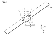
- FIG. 2 is a perspective view showing an appearance of a primary conductor included in the current sensor according to Embodiment 1 of the present invention.
- FIG. 3 is an exploded perspective view showing the configuration of the magnetic sensor unit provided in the current sensor according to Embodiment 1 of the present invention.
- FIG. 4 is a perspective view showing an appearance of a housing of the magnetic sensor unit provided in the current sensor according to the first embodiment of the present invention.
- FIG. 5 is a cross-sectional view of the current sensor according to Embodiment 1 of the present invention, as viewed from the direction of arrows VV in FIG.
- FIG. 6 is a cross-sectional view of the current sensor according to Embodiment 1 of the present invention, as viewed from the direction of arrows VI-VI in FIG.
- FIG. 7 is a circuit diagram showing a circuit configuration of the current sensor according to Embodiment 1 of the present invention.
- the width direction of primary conductors 110a and 110b which will be described later, is the X-axis direction, and the length direction of primary conductors 110a and 110b is the Y-axis direction.
- the thickness direction of 110b is illustrated as the Z-axis direction. 5 and 6, the housing 150 is not shown.
- FIG. 5 in the width direction (X-axis direction) of the primary conductors 110a and 110b, a center line passing through the center of each of the first magnetic sensor element 120a and the second magnetic sensor element 120b described later is indicated by Lc. Yes.
- FIG. 7 shows a circuit configuration of a portion corresponding to one primary conductor 110a, 110b.
- the current sensor 100 includes a first current sensor unit 100a and a second current sensor unit 100b.
- the current sensor 100 includes two current sensor units, but the number of current sensor units included in the current sensor is not limited to two and may be plural. For example, when the current sensor 100 is applied to a three-phase three-wire wiring, the current sensor 100 includes three current sensor units.
- Each of the first current sensor unit 100a and the second current sensor unit 100b includes a primary conductor 110a, 110b that is a conductor through which a current to be measured flows, and a magnetic field generated by the current to be measured through the primary conductors 110a, 110b.
- the first magnetic sensor element 120a and the second magnetic sensor element 120b are provided for detecting the strength of the first magnetic sensor element.
- the primary conductors 110a and 110b include the front surface and the back surface, the length direction (Y-axis direction), the width direction (X-axis direction) orthogonal to the length direction (Y-axis direction), and the length A plate shape having a thickness direction (Z-axis direction) orthogonal to the vertical direction (Y-axis direction) and the width direction (X-axis direction).
- the current to be measured is divided into two flow paths as will be described later, and the primary conductors 110a and 110b are indicated by arrows 1a and 1b. It flows in the length direction (Y-axis direction) of the primary conductors 110a and 110b.
- the primary conductors 110a and 110b include a first flow path portion and a second flow path portion in which a current to be measured flows in a halfway direction (Y-axis direction).
- the primary conductors 110a and 110b are bent so as to protrude in one of the thickness directions (Z-axis direction) of the primary conductors 110a and 110b and extend in the length direction (Y-axis direction).
- the arch-shaped part 111 which is the first flow path part constituting one of the flow paths, and the length direction (Y-axis direction) is bent so as to protrude to the other of the thickness direction (Z-axis direction).
- an inverted arch-shaped portion 116 that is a second flow path portion that constitutes one of the two flow paths. That is, the first flow path portion bulges to the surface side of the primary conductors 110a and 110b when viewed from the width direction (X-axis direction) of the primary conductors 110a and 110b.
- the second channel portion bulges to the back side of the primary conductors 110a and 110b when viewed from the width direction (X-axis direction) of the primary conductors 110a and 110b.
- the arch-shaped portion 111 and the reverse arch-shaped portion 116 are arranged side by side in the width direction (X-axis direction) of the primary conductors 110a and 110b, and the opening 10 is formed inside the arch-shaped portion 111 and the reverse arch-shaped portion 116.
- the opening 10 is formed as an area surrounded by the first flow path part and the second flow path part when viewed from the width direction (X-axis direction) of the primary conductors 110a and 110b.
- the arch-shaped portion 111 is spaced apart from each other by a first protrusion 112 and a second protrusion that protrude perpendicularly to the main surfaces of the primary conductors 110a and 110b. It is comprised from the part 113 and the extension part 114 extended in the length direction (Y-axis direction) of the primary conductors 110a and 110b, and connecting the 1st protrusion part 112 and the 2nd protrusion part 113.
- the shape of the arch-shaped portion 111 is not limited to this, and may be, for example, C-shaped or semicircular when viewed from the width direction (X-axis direction) of the primary conductors 110a and 110b. .
- the reverse arched portion 116 is spaced apart from each other by the third and fourth protruding portions 117 and 118 protruding perpendicularly to the main surfaces of the primary conductors 110a and 110b, and the lengths of the primary conductors 110a and 110b.
- the extending portion 119 extends in the vertical direction (Y-axis direction) and connects the third protruding portion 117 and the fourth protruding portion 118.
- the shape of the reverse arch-shaped portion 116 is not limited to this, and may be a C-shape or a semicircular shape when viewed from the width direction (X-axis direction) of the primary conductors 110a and 110b, for example. Good.
- the arched portion 111 and the reverse arched portion 116 have the same shape, but may have different shapes.
- the distance between the extending portion 114 and the extending portion 119 in the thickness direction (Z-axis direction) of the primary conductors 110a and 110b is Hb.
- the primary conductors 110a and 110b are provided with slits 115 extending in the length direction (Y-axis direction) of the primary conductors 110a and 110b.
- the slit 115 is adjacent to the arched portion 111 in the width direction (X-axis direction) of the primary conductors 110a and 110b. Note that the slit 115 is not necessarily provided.
- the slit 115 is located at the center of the primary conductors 110a and 110b in the width direction (X-axis direction) of the primary conductors 110a and 110b.
- the slit 115 is located between the arch-shaped portion 111 and the reverse arch-shaped portion 116. That is, since the slit 115 is provided, the first flow path portion and the second flow path portion are positioned at a distance from each other in the width direction (X-axis direction) of the primary conductors 110a and 110b. Yes.
- the slit 115 is in contact with the entirety of the arched portion 111 in the longitudinal direction of the primary conductors 110a and 110b), but the range in which the slit 115 is provided is not limited to this, A slit 115 may be provided so as to contact only a part of the arched portion 111.
- the slit 115 is rectangular when viewed from the thickness direction (Z-axis direction) of the primary conductors 110a and 110b.
- the shape of the slit 115 is not limited to this, and may be elliptical.
- the primary conductors 110a and 110b of each of the first current sensor unit 100a and the second current sensor unit 100b are arranged in parallel with a distance from each other and extend in the length direction (Y-axis direction). In the present embodiment, the primary conductors 110a and 110b are aligned with each other at an interval in the width direction (X-axis direction). However, the direction in which the primary conductors are arranged is not limited to the width direction (X-axis direction) and may be any direction.
- the arched portion 111 and the reverse arched portion 116 of the first current sensor unit 100a are displaced from the arched portion 111 and the reverse arched portion 116 of the second current sensor unit 100b in the length direction (Y-axis direction). is doing.
- a center line C1 that passes through the center of the opening 10 of the primary conductor 110a and extends in the width direction (X-axis direction) and the opening 10 of the primary conductor 110b. Is shifted by a distance M1 in the length direction (Y-axis direction) from the center line C2 extending in the width direction (X-axis direction).
- the primary conductors 110a and 110b are made of copper.
- the material of the primary conductors 110a and 110b is not limited to this, and may be a metal such as silver, aluminum, or iron, or an alloy containing these metals.
- the primary conductors 110a and 110b may be subjected to surface treatment.
- at least one plating layer made of a metal such as nickel, tin, silver, or copper, or an alloy containing these metals may be provided on the surfaces of the primary conductors 110a and 110b.
- the primary conductors 110a and 110b are formed by press working.
- the method of forming the primary conductors 110a and 110b is not limited to this, and the primary conductors 110a and 110b may be formed by cutting or casting.
- each of the first magnetic sensor element 120a and the second magnetic sensor element 120b is mounted on a substrate 130 together with electronic components 140a and 140b such as an amplifier and a passive element.
- the first magnetic sensor element 120a and the second magnetic sensor element 120b are displaced from each other in the length direction (Y-axis direction) of the primary conductors 110a and 110b, and the width direction of the primary conductors 110a and 110b. They are located side by side (in the X-axis direction).
- the magnetic sensor unit 160 is configured by fixing the substrate 130 in the casing 150 having electrical insulation. That is, each of the first magnetic sensor element 120a, the second magnetic sensor element 120b, the electronic components 140a and 140b, and the substrate 130 is accommodated in the housing 150.
- the substrate 130 is a printed wiring board, and includes a base material such as glass epoxy or alumina, and a wiring formed by patterning a metal foil such as copper provided on the surface of the base material.
- the casing 150 has a substantially rectangular parallelepiped outer shape, and includes a lower casing 151 and an upper casing 152.
- the upper casing 152 is provided with a wire harness outlet 152 p connected to the substrate 130.
- the housing 150 is formed of an engineering plastic such as PPS (polyphenylene sulfide). Since PPS has high heat resistance, it is preferable as a material for the housing 150 in consideration of heat generation of the primary conductors 110a and 110b.
- PPS polyphenylene sulfide
- fastening with screws thermal welding with resin, bonding with an adhesive, or the like can be used.
- nonmagnetic screws it is preferable to use nonmagnetic screws so as not to disturb the magnetic field.
- the magnetic sensor unit 160 is inserted into the opening 10 formed by the arched portion 111 and the reverse arched portion 116. Accordingly, the first magnetic sensor element 120a is disposed on the inner side of the arch-shaped portion 111 and is located on the back side of the extending portion 114, and the second magnetic sensor element 120b is disposed on the inner side of the reverse arch-shaped portion 116.
- the extension portion 119 is located on the surface side. That is, the first magnetic sensor element 120a is located inside the region as seen from the width direction (X-axis direction) of the primary conductors 110a and 110b, and is located on the back surface side of one flow path portion. Yes.
- the second magnetic sensor element 120b is located inside the region as viewed from the width direction (X-axis direction) of the primary conductors 110a and 110b, and is located on the surface side of the other flow path portion.
- the slit 115 is located between the first magnetic sensor element 120a and the second magnetic sensor element 120b when viewed from the thickness direction (Z-axis direction) of the primary conductors 110a and 110b.
- the slit 115 is located between the first magnetic sensor element 120a and the second magnetic sensor element 120b.
- the casing 150 is in contact with at least a part of the inner surface of the arched portion 111.
- the upper housing 152 is in contact with at least a part of the back surface of the extending portion 114.
- the housing 150 is in contact with at least a part of the inner surface of the inverted arched portion 116.
- the lower housing 151 is in contact with at least a part of the surface of the extending portion 119.
- each of the first magnetic sensor element 120a and the second magnetic sensor element 120b of the first current sensor unit 100a is viewed from the width direction (X-axis direction) of the primary conductors 110a and 110b.
- the first magnetic sensor element 120a and the second magnetic sensor element 120b of the second current sensor unit 100b are located outside the opening 10 of the second current sensor unit 100b, and the primary conductors 110a and 110b When viewed from the width direction (X-axis direction), it is located outside the opening 10 of the first current sensor unit 100a.
- Each of the first magnetic sensor element 120a and the second magnetic sensor element 120b of the first current sensor unit 100a is one of the second current sensor unit 100b when viewed from the width direction (X-axis direction) of the primary conductors 110a and 110b.
- Each of the first magnetic sensor element 120a and the second magnetic sensor element 120b of the second current sensor unit 100b is viewed from the width direction (X-axis direction) of the primary conductors 110a and 110b. Thus, it overlaps the primary conductor 110a of the first current sensor unit 100a.
- the center line Lc passing through the center of each of the first magnetic sensor element 120a and the second magnetic sensor element 120b of the first current sensor unit 100a has an extension part 114 and an extension part 119 of the primary conductor 110a. It is located in the middle. That is, in the thickness direction (Z-axis direction) of the primary conductor 110a, the distance between the lower surface of the extending portion 114 and the center line Lc, and the distance between the upper surface of the extending portion 119 and the center line Lc are: Hb / 2.
- the center line Lc passing through each of the magnetic sensing surfaces of the first magnetic sensor element 120a and the second magnetic sensor element 120b of the second current sensor unit 100b is an extension part 114 and an extension part of the primary conductor 110b. It is located in the middle of 119. That is, in the thickness direction (Z-axis direction) of the primary conductor 110b, the distance between the lower surface of the extending portion 114 and the center line Lc and the distance between the upper surface of the extending portion 119 and the center line Lc are: Hb / 2.
- the distance M1 between the center line C1 and the center line C2 is set so that a portion other than the arch-shaped portion 111 and a portion other than the reverse arch-shaped portion 116 of the primary conductor 110a are located.
- the substrate 130 is disposed so that the mounting surface of the substrate 130 and the main surfaces of the primary conductors 110a and 110b are parallel, but the mounting surface of the substrate 130 and the primary conductors 110a and 110b are not aligned.
- the substrate 130 may be arranged so as to be perpendicular to the main surface.
- Each of the first magnetic sensor element 120a and the second magnetic sensor element 120b detects a magnetic field in the width direction (X-axis direction) of the primary conductors 110a and 110b.
- each of the first magnetic sensor element 120a and the second magnetic sensor element 120b has a detection axis 2 oriented in the width direction (X-axis direction) of the primary conductors 110a and 110b.
- each of the first magnetic sensor element 120a and the second magnetic sensor element 120b has the detection axis 2, and is arranged so that the detection axis 2 faces the width direction (X-axis direction) of the primary conductors 110a and 110b. ing.
- Each of the first magnetic sensor element 120a and the second magnetic sensor element 120b outputs a positive value when a magnetic field directed in one direction of the detection axis 2 is detected, and is opposite to the one direction of the detection axis 2. It has an odd function input / output characteristic that outputs a negative value when a magnetic field directed in the direction is detected.
- each of the first magnetic sensor element 120a and the second magnetic sensor element 120b is a Wheatstone bridge type bridge composed of four AMR (Anisotropic Magneto Resistance) elements. It has a circuit.
- each of the first magnetic sensor element 120a and the second magnetic sensor element 120b is replaced with an AMR element, GMR (Giant Magneto Resistance), TMR (Tunnel Magneto Resistance), BMR (Ballistic Magneto Resistance), CMR (Colossal Magneto Magneto). It may have a magnetoresistive element such as Resistance).
- each of the first magnetic sensor element 120a and the second magnetic sensor element 120b may have a half-bridge circuit composed of two magnetoresistive elements.
- a magnetic sensor element having a Hall element a magnetic sensor element having an MI (Magneto Impedance) element utilizing a magnetic impedance effect, or a fluxgate type magnetic sensor.
- MI Magnetic Impedance
- An element or the like can be used as the first magnetic sensor element 120a and the second magnetic sensor element 120b.
- Magnetic elements such as a magnetoresistive element and a Hall element may be packaged with a resin, or may be potted with a silicone resin or an epoxy resin.
- the plurality of magnetic elements When a plurality of magnetic elements are packaged, the plurality of magnetic elements may be packaged in one, or each of the plurality of magnetic elements may be packaged separately. In addition, a plurality of magnetic elements and electronic components may be integrated and packaged together.
- the AMR element has an odd function input / output characteristic by including a barber pole type electrode.
- each of the magnetoresistive elements of the first magnetic sensor element 120a and the second magnetic sensor element 120b includes a barber pole type electrode, and thereby has a predetermined direction with respect to the magnetization direction of the magnetoresistive film in the magnetoresistive element. It is biased so that current flows in an angled direction.
- the magnetization direction of the magnetoresistive film is determined by at least one of the shape anisotropy of the magnetoresistive film and the bias magnetic field.
- a method for determining the magnetization direction of the AMR element a method of applying a bias magnetic field by arranging a permanent magnet or a coil in the vicinity of the magnetoresistive film constituting the AMR element, or replacement in the magnetoresistive film constituting the AMR element.
- a method of providing a bond may be used.
- the permanent magnet may be composed of a sintered magnet, a bonded magnet, or a thin film.
- the kind of permanent magnet is not particularly limited, and a ferrite magnet, a samarium cobalt magnet, an alnico magnet, a neodymium magnet, or the like can be used.
- the magnetization direction of the magnetoresistive film in the magnetoresistive element of the first magnetic sensor element 120a and the magnetization direction of the magnetoresistive film in the magnetoresistive element of the second magnetic sensor element 120b are the same direction. Thereby, the fall of the output accuracy by the influence of an external magnetic field can be made small.
- Each of the first magnetic sensor element 120a and the second magnetic sensor element 120b is configured such that the detection sensitivity changes according to the strength of the bias magnetic field in the length direction (Y-axis direction) of the primary conductors 110a and 110b. ing. Specifically, as shown in FIG. 3, each of the first magnetic sensor element 120 a and the second magnetic sensor element 120 b has a sensitivity change axis 3 orthogonal to the detection axis 2. As shown in FIGS. 3 and 6, each of the first magnetic sensor element 120a and the second magnetic sensor element 120b has the sensitivity change axis 3 along the length direction (Y-axis direction) of the primary conductors 110a and 110b. Has been placed. That is, the sensitivity change axis 3 is oriented in the length direction (Y-axis direction) of the primary conductors 110a and 110b.
- each of the first magnetic sensor element 120a and the second magnetic sensor element 120b changes when a magnetic field in the direction along the sensitivity change axis 3 is applied.
- each of the first magnetic sensor element 120a and the second magnetic sensor element 120b has an output sensitivity when a magnetic field is applied in the direction along the sensitivity change axis 3 in the direction opposite to the bias magnetic field application direction.
- the output sensitivity is low when a magnetic field having the same direction as the bias magnetic field application direction is applied in the direction along the sensitivity change axis 3.
- the first magnetic sensor element 120a and the second magnetic sensor element 120b each have an output of 0 when only a magnetic field in the direction along the sensitivity change axis 3 is applied.
- the current sensor 100 calculates the current to be measured flowing through the primary conductors 110a and 110b by calculating the detection value of the first magnetic sensor element 120a and the detection value of the second magnetic sensor element 120b. It further includes a calculation unit 190 that calculates a value.
- the calculation unit 190 is a differential amplifier. However, the calculation unit 190 may be a subtracter.
- the current to be measured flowing through the primary conductors 110 a and 110 b is generated between the first flow path portion that passes through the arch-shaped portion 111 and the second flow path portion that passes through the reverse arch-shaped portion 116. It flows separately in two flow paths.
- a magnetic field that circulates in each flow path is generated according to the so-called right-handed screw law.
- the first magnetic sensor element 120a since the first magnetic sensor element 120a is arranged inside the arch-shaped portion 111, the first magnetic sensor element 120a includes a magnetic field 112e that circulates around the first protrusion 112, and A magnetic field 113e that circulates around the second protrusion 113 and a magnetic field 114e that circulates around the extension 114 are applied. Thereby, since the magnetic field applied to the magnetoresistive element of the first magnetic sensor element 120a becomes strong, the sensitivity of the first magnetic sensor element 120a with respect to the measurement current flowing through the primary conductors 110a and 110b increases.
- the second magnetic sensor element 120b Since the second magnetic sensor element 120b is disposed inside the inverted arched portion 116, the second magnetic sensor element 120b includes a magnetic field that circulates around the third protrusion 117 and a magnetic field that circulates around the fourth protrusion 118. And a magnetic field 119e that goes around the extending portion 119 is applied. As a result, the magnetic field applied to the magnetoresistive element of the second magnetic sensor element 120b becomes stronger, so that the sensitivity of the second magnetic sensor element 120b with respect to the measurement current flowing through the primary conductors 110a and 110b increases.
- the direction of the magnetic flux in the X-axis direction is opposite to the position on the back surface side of the extending portion 114 and the position on the front surface side of the extending portion 119. That is, since the direction of the magnetic flux acting on the first magnetic sensor element 120a is opposite to the direction of the magnetic flux acting on the second magnetic sensor element 120b, it is generated by the current to be measured flowing through the primary conductors 110a and 110b. Regarding the strength of the magnetic field, the phase of the detection value of the first magnetic sensor element 120a is opposite to the phase of the detection value of the second magnetic sensor element 120b. Therefore, if the magnetic field intensity detected by the first magnetic sensor element 120a is a positive value, the magnetic field intensity detected by the second magnetic sensor element 120b is a negative value.
- the detection value of the first magnetic sensor element 120a and the detection value of the second magnetic sensor element 120b are calculated by the calculation unit 190. Specifically, the calculation unit 190 subtracts the detection value of the second magnetic sensor element 120b from the detection value of the first magnetic sensor element 120a. From this result, the value of the current to be measured flowing through the primary conductors 110a and 110b is calculated.
- the external magnetic field source is physically located between the first magnetic sensor element 120a and the second magnetic sensor element 120b. Can not be located in.
- the direction of the magnetic field component in the direction of the detection axis in the magnetic field applied to the first magnetic sensor element 120a from the external magnetic field source and the detection of the magnetic field applied to the second magnetic sensor element 120b from the external magnetic field source is the same direction. Therefore, when the strength of the external magnetic field detected by the first magnetic sensor element 120a is a positive value, the strength of the external magnetic field detected by the second magnetic sensor element 120b is also a positive value.
- the calculation unit 190 subtracts the detection value of the second magnetic sensor element 120b from the detection value of the first magnetic sensor element 120a, so that the magnetic field from the external magnetic field source is hardly detected. That is, the influence of the external magnetic field is reduced.
- the directions of the detection axes with positive detection values may be opposite to each other (opposite 180 °).
- the strength of the external magnetic field detected by the first magnetic sensor element 120a is a positive value
- the strength of the external magnetic field detected by the second magnetic sensor element 120b is a negative value.
- the phase of the detection value of the first magnetic sensor element 120a and the phase of the detection value of the second magnetic sensor element 120b are in phase. It becomes.
- an adder or an addition amplifier is used as the calculation unit 190 instead of the differential amplifier.
- the detection value of the first magnetic sensor element 120a is added to the detection value of the first magnetic sensor element 120a and the detection value of the second magnetic sensor element 120b by an adder or an addition amplifier.
- the absolute value and the absolute value of the detection value of the second magnetic sensor element 120b are subtracted. Thereby, the magnetic field from the external magnetic field source is hardly detected. That is, the influence of the external magnetic field is reduced.
- the detection value of the first magnetic sensor element 120a and the detection value of the second magnetic sensor element 120b are added by an adder or an addition amplifier.
- the value of the current to be measured flowing through the primary conductors 110a and 110b is calculated.
- an adder or an addition amplifier may be used as the calculation unit in place of the differential amplifier while the input / output characteristics of the first magnetic sensor element 120a and the second magnetic sensor element 120b have opposite polarities.
- the current sensor 100 increases the sensitivity of each of the first magnetic sensor element 120a and the second magnetic sensor element 120b with respect to the measurement current flowing through the primary conductors 110a and 110b.
- the effect of an external magnetic field can be reduced while increasing the sensitivity of the.
- the magnetic field 110be that goes around the primary conductor 110b is orthogonal to the detection axis 2 with respect to each of the first magnetic sensor element 120a and the second magnetic sensor element 120b of the first current sensor unit 100a. Acting in the thickness direction (Z-axis direction) of the primary conductor 110a. Therefore, the output of each of the first magnetic sensor element 120a and the second magnetic sensor element 120b of the first current sensor unit 100a by the magnetic field 110be that goes around the primary conductor 110b is almost zero. Thereby, it can suppress that the magnetic field which the 2nd current sensor unit 100b affects on the measured value of the 1st current sensor unit 100a, and can reduce the measurement error of the 1st current sensor unit 100a.
- the magnetic field that circulates around the primary conductor 110a is a direction that is perpendicular to the detection axis 2 with respect to each of the first magnetic sensor element 120a and the second magnetic sensor element 120b of the second current sensor unit 100b. It acts in the thickness direction (Z-axis direction) of the conductor 110b. Therefore, the outputs of the first magnetic sensor element 120a and the second magnetic sensor element 120b of the second current sensor unit 100b by the magnetic field that circulates around the primary conductor 110a are almost zero. Thereby, it can suppress that the magnetic field which the 1st current sensor unit 100a generates affects the measured value of the 2nd current sensor unit 100b, and can reduce the measurement error of the 2nd current sensor unit 100b.
- the measurement error can be reduced by suppressing the influence of the magnetic field that circulates around the primary conductor adjacent to the corresponding primary conductor and the external magnetic field.
- the arch-shaped portion 111 and the reverse arch-shaped portion 116 of the first current sensor unit 100a are displaced from the arch-shaped portion 111 and the reverse arch-shaped portion 116 of the second current sensor unit 100b in the length direction (Y-axis direction). Therefore, the influence of the magnetic field around the primary conductor adjacent to the corresponding primary conductor is suppressed, so there is no need to bend the primary conductor in the same plane.
- the current sensor 100 can be reduced in size by reducing the planar space occupied by 110a and 110b.
- each of the first current sensor unit 100a and the second current sensor unit 100b has a structure in which the magnetic sensor unit 160 is inserted into the opening 10 and assembled to the primary conductors 110a and 110b.
- the current sensor 100 can be easily assembled, and the components of the magnetic sensor unit 160 can be protected from external force by the arched portion 111 and the reverse arched portion 116. Further, the current sensor 100 can be reduced in height, integrated, and downsized.
- the primary conductors 110a and 110b are formed of a single conductor, the number of parts can be reduced and the cost can be reduced compared to the case where the primary conductors 110a and 110b are formed of a plurality of conductors. Can be planned.
- the measurement current flows through the primary conductors 110a and 110b.
- the calorific value of the arched part 111 and the calorific value of the reverse arched part 116 can be made equal.
- the temperature around the magnetoresistive element of the first magnetic sensor element 120a can be made substantially the same as the temperature around the magnetoresistive element of the second magnetic sensor element 120b.
- the error of the measured value of the current sensor 100 can be reduced.
- Embodiment 2 the current sensor according to the second embodiment of the present invention will be described in comparison with the current sensor according to the comparative example.
- the structure of the current sensor unit with which each of Embodiment 2 and the current sensor of a comparative example is provided is the same as that of the current sensor 100 which concerns on Embodiment 1, description is not repeated about the structure of a current sensor unit.
- the current sensor of the second embodiment and the comparative example is applied to, for example, a three-phase three-wire wiring such as an inverter, and includes three current sensor units.
- FIG. 8 is a perspective view showing an appearance of a current sensor according to a comparative example.
- FIG. 9 is a cross-sectional view seen from the direction of the arrow IX-IX in FIG.
- FIG. 10 is a perspective view showing an appearance of a current sensor according to Embodiment 2 of the present invention.
- FIG. 11 is a cross-sectional view seen from the direction of the arrow XI-XI in FIG. 8 to 11, the magnetic sensor unit 160 is not shown.
- a current sensor 900 according to a comparative example includes a first current sensor unit 900a, a second current sensor unit 900b, and a third current sensor unit 900c.
- Each of the first current sensor unit 900a, the second current sensor unit 900b, and the third current sensor unit 900c includes a primary conductor 110a through which a current to be measured flows and a magnetic field generated by a current to be measured through the primary conductor 110a.
- the first magnetic sensor element 120a and the second magnetic sensor element 120b are provided for detecting the strength of the first magnetic sensor element.
- the magnetic sensor unit 160 is inserted into the opening 10 of the primary conductor 110a.
- the current to be measured is divided into two flow paths, and the primary conductor 110a is indicated by arrows 1a, 1b, and 1c. As shown, it flows in the length direction (Y-axis direction) of the primary conductor 110a.
- the primary conductors 110a of each of the first current sensor unit 900a, the second current sensor unit 900b, and the third current sensor unit 900c are arranged in the length direction (Y-axis direction) with an interval in the width direction (X-axis direction). ).
- the reverse arcuate portion 116 is located on a virtual straight line extending in the width direction (X-axis direction) of the primary conductor 110a.
- each of the first current sensor unit 900a, the second current sensor unit 900b, and the third current sensor unit 900c passes through the center of the opening 10 of the primary conductor 110a and extends in the width direction (X-axis direction).
- the center line C1 is located on the same straight line.
- the current sensor 200 includes a first current sensor unit 200a, a second current sensor unit 200b, and a third current sensor unit 200c.
- Each of the first current sensor unit 200a, the second current sensor unit 200b, and the third current sensor unit 200c flows through the primary conductors 110a, 110b, and 110c through which the current to be measured flows and the primary conductors 110a, 110b, and 110c.
- a first magnetic sensor element 120a and a second magnetic sensor element 120b that detect the strength of a magnetic field generated by a current to be measured are provided.
- the magnetic sensor unit 160 is inserted into the opening 10 of the primary conductors 110a, 110b, and 110c. Yes.
- the current to be measured is divided into two flow paths, and the primary conductors 110a, 110b, and 110c are moved to the arrows 1a, As indicated by 1b and 1c, the primary conductors 110a, 110b and 110c flow in the length direction (Y-axis direction).
- the primary conductors 110a, 110b, 110c of the first current sensor unit 200a, the second current sensor unit 200b, and the third current sensor unit 200c are longitudinally spaced from each other in the width direction (X-axis direction). It extends in the (Y-axis direction).
- the arched part 111 and the reverse arched part 116 of the first current sensor unit 200a, the arched part 111 and the reverse arched part 116 of the second current sensor unit 200b, the arched part 111 of the third current sensor unit 200c, and The reverse arcuate portions 116 are shifted from each other in the length direction (Y-axis direction).
- the center line C3 and the center line C2 that pass through the center of the opening 10 of the primary conductor 110c and extend in the width direction (X-axis direction) are shifted by a distance M2 in the length direction (Y-axis direction).
- the distance M1 between the center line C1 and the center line C2 is set so that a portion other than the arch-shaped portion 111 and a portion other than the reverse arch-shaped portion 116 of the primary conductor 110a are located.
- the distance M2 between the center line C2 and the center line C3 is set so that a portion other than the arch-shaped portion 111 and a portion other than the reverse arch-shaped portion 116 of the primary conductor 110b are located.
- the influence of the magnetic field generated by each of the first current sensor unit 900a and the second current sensor unit 900b on the measured value of the third current sensor unit 900c and the second embodiment.
- a simulation analysis result that verifies the influence of the magnetic field generated by each of the first current sensor unit 200a and the second current sensor unit 200b on the measurement value of the third current sensor unit 200c will be described. .
- a current of 600 A 300 A in the first flow path and 300 A in the second flow path was passed through each of the primary conductors 110 a, 110 b, and 110 c.
- the magnetic flux density distribution of the magnetic field to be measured on the center line Lc was analyzed by simulation.
- the start point of the center line Lc is one end of the primary conductor
- the end point of the center line Lc is the other end of the primary conductor.
- FIG. 12 shows the result of a simulation analysis of the magnetic flux density of the magnetic field generated when a current outside the measurement target is passed through the two primary conductors of the current sensor according to the comparative example, in the same cross-sectional view as FIG. FIG.
- the magnetic flux density of the magnetic field directed to one side in the width direction (X axis direction) of the primary conductor 110a is directed to the other in the width direction (X axis direction) E1 to E5 in descending order.
- E11 to E16 are shown in descending order of the magnetic flux density of the magnetic field.
- FIG. 13 is a graph showing the displacement of the magnetic flux density of the X-axis direction component from the start point to the end point on the center line Lc in FIG.
- the vertical axis indicates the magnetic flux density (T) of the X-axis direction component
- the horizontal axis indicates the distance (mm) from the starting point in the X-axis direction.
- FIG. 14 shows the same cross section as FIG. 11, showing the result of simulation analysis of the magnetic flux density of the magnetic field generated when a current outside the measurement target is passed through the two primary conductors of the current sensor according to the second embodiment of the present invention. It is the contour map shown visually.
- FIG. 14 in the order of increasing magnetic flux density of the magnetic field directed to one side in the width direction (X-axis direction) of the primary conductors 110a, 110b, 110c, the width of the primary conductor 110a in the width direction (X-axis direction) is increased.
- E11 to E16 are shown in descending order of the magnetic flux density of the magnetic field directed to the other side.
- FIG. 15 is a graph showing the displacement of the magnetic flux density of the X-axis direction component from the start point to the end point on the center line Lc in FIG.
- the vertical axis represents the magnetic flux density (T) of the X-axis direction component
- the horizontal axis represents the distance (mm) from the starting point in the X-axis direction.
- a magnetic field directed to the other side in the width direction (X-axis direction) of the primary conductor 110a was generated above the extending portion 114 and above the extending portion 119.
- the magnetic field generated by each of the first current sensor unit 900a and the second current sensor unit 900b affects the measurement value of the third current sensor unit 900c.
- the primary sensor 110a, 110b is directed to one side in the width direction (X-axis direction) below the primary conductors 110a, 110b. Magnetic field is generated. A magnetic field directed to the other side in the width direction (X-axis direction) of the primary conductors 110a and 110b was generated above the primary conductors 110a and 110b.
- the magnetic flux density of the magnetic field oriented in the width direction (X-axis direction) of the primary conductor 110a is entirely on the center line Lc. It was almost 0T.
- each of the first current sensor unit 200a and the second current sensor unit 200b is generated in the measurement value of the third current sensor unit 200c. It was confirmed that the measurement error of the third current sensor unit 200c can be reduced by suppressing the influence of the magnetic field.
- the measurement error can be reduced by suppressing the influence of the magnetic field that goes around the primary conductor adjacent to the corresponding primary conductor.
- Embodiment 3 a current sensor according to Embodiment 3 of the present invention will be described.
- the current sensor 300 according to the third embodiment is different from the current sensor 200 according to the second embodiment only in the arrangement of the third current sensor unit, and therefore the same reference numerals are used for the same configurations as the current sensor 200 according to the second embodiment. Will not be repeated.
- FIG. 16 is a perspective view showing an appearance of a current sensor according to Embodiment 3 of the present invention. In FIG. 16, the magnetic sensor unit 160 is not shown.
- the current sensor 300 includes a first current sensor unit 300a, a second current sensor unit 300b, and a third current sensor unit 300c.
- Each of the first current sensor unit 300a, the second current sensor unit 300b, and the third current sensor unit 300c includes the primary conductors 110a and 110b through which the current to be measured flows and the current to be measured through the primary conductors 110a and 110b.
- the first magnetic sensor element 120a and the second magnetic sensor element 120b are provided for detecting the strength of the magnetic field generated by.
- the magnetic sensor unit 160 is inserted into the opening 10 of the primary conductors 110a and 110b.
- the current to be measured is divided into two flow paths, and the primary conductors 110a and 110b are moved to the arrows 1a, 1b, As indicated by 1c, the primary conductors 110a and 110b flow in the length direction (Y-axis direction).
- the primary conductors 110a and 110b of each of the first current sensor unit 300a, the second current sensor unit 300b, and the third current sensor unit 300c are spaced from each other in the width direction (X-axis direction) in the length direction (Y (Axial direction).
- the arch-shaped portion 111 and the reverse arch-shaped portion 116 of the first current sensor unit 300a and the arch-shaped portion 111 and the reverse arch-shaped portion 116 of the second current sensor unit 300b are mutually in the length direction (Y-axis direction). The position is shifted.
- the arched part 111 and the reverse arched part 116 of the second current sensor unit 300b and the arched part 111 and the reverse arched part 116 of the third current sensor unit 300c are mutually in the length direction (Y-axis direction). The position is shifted.
- the arched portion 111 and the reverse arched portion 116 of the first current sensor unit 300a and the arched portion 111 and the reverse arched portion 116 of the third current sensor unit 300c are mutually in the length direction (Y-axis direction). It is located without deviation.
- the arch-shaped portion 111 and the reverse arch-shaped portion 116 of the first current sensor unit 300a and the arch-shaped portion 111 and the reverse arch-shaped portion 116 of the third current sensor unit 300c are the width direction (X-axis direction) of the primary conductor 110a. ) Is located on a virtual straight line extending to). That is, a center line C1 that passes through the center of the opening 10 of the primary conductor 110a and extends in the width direction (X-axis direction) in each of the first current sensor unit 300a and the third current sensor unit 300c is the same. Located on a straight line.
- the center line C1 that passes through the center of the opening 10 of the primary conductor 110a and extends in the width direction (X-axis direction) passes through the center of the opening 10 of the primary conductor 110b.
- the center line C2 extending in the width direction (X-axis direction) is shifted by a distance M1 in the length direction (Y-axis direction).
- the arch-shaped portion 111 and the reverse arch-shaped portion 116 of the primary conductors adjacent to each other may be positioned so as to be shifted in the length direction (Y-axis direction) of the primary conductor.
- the arch-shaped portion 111 and the reverse arch-shaped portion 116 of the primary conductors adjacent to each other may be positioned so as to be shifted in the length direction (Y-axis direction) of the primary conductor.
- Embodiment 4 a current sensor according to Embodiment 4 of the present invention will be described.
- the current sensor according to the fourth embodiment is different from the current sensor 100 according to the first embodiment only in the shape of the primary conductor, the description of the configuration similar to that of the current sensor 100 according to the first embodiment will not be repeated.
- FIG. 17 is a perspective view showing an appearance of a primary conductor provided in a current sensor according to Embodiment 4 of the present invention.
- the primary conductor 410a included in the current sensor according to the fourth embodiment of the present invention has an arch shape having a semicircular shape when viewed from the width direction (X-axis direction) of the primary conductor 410a. 411 and reverse arcuate portion 416.
- An opening 40 is formed inside the arcuate portion 411 and the reverse arcuate portion 416.
- a magnetic sensor unit is inserted into the opening 40 of the primary conductor 410a.
- the housing of the magnetic sensor unit has a substantially cylindrical outer shape.
- the current sensor according to the present embodiment it is possible to reduce the size while reducing the measurement error by suppressing the influence of the magnetic field that circulates around the primary conductor adjacent to the corresponding primary conductor and the external magnetic field.
- Embodiment 5 a current sensor according to Embodiment 5 of the present invention will be described.
- the current sensor according to the fifth embodiment is different from the current sensor 100 according to the first embodiment only in the shape of the primary conductor, the description of the configuration similar to that of the current sensor 100 according to the first embodiment will not be repeated.
- FIG. 18 is a perspective view showing an external appearance of a primary conductor provided in a current sensor according to Embodiment 5 of the present invention.
- FIG. 19 is a side view of the primary conductor of FIG. 18 as viewed from the direction of arrow XIX.
- the plate-shaped primary conductor 510a included in the current sensor according to Embodiment 5 of the present invention includes a front surface and a back surface, and includes a length direction (Y-axis direction) and a length direction (Y A width direction (X-axis direction) orthogonal to the axial direction) and a thickness direction (Z-axis direction) orthogonal to the length direction (Y-axis direction) and the width direction (X-axis direction).
- the first flow path portion 511 bulges to the surface side of the primary conductor 510a when viewed from the width direction (X-axis direction) of the primary conductor 510a.
- the second flow path portion 516 bulges to the back surface side of the primary conductor 510a when viewed from the width direction (X-axis direction) of the primary conductor 510a.
- the second flow path portion 516 is aligned with the first flow path portion 511 in the width direction (X-axis direction) of the primary conductor 510a.
- a region 50 surrounded by the first channel portion 511 and the second channel portion 516 is formed when viewed from the width direction (X-axis direction) of the primary conductor 510a.
- the slit 515 is located at the center of the primary conductor 510a in the width direction (X-axis direction) of the primary conductor 510a.
- Each of the first flow path portion 511 and the second flow path portion 516 has a semi-oval shape when viewed from the width direction (X-axis direction) of the primary conductor 510a.
- the first flow path portion 511 is spaced apart from each other by a first protrusion 512 and a second protrusion 513 protruding in a circular arc shape from the surface of the primary conductor 510a, and the length direction (Y-axis of the primary conductor 510a).
- the first protrusion 512 and the second protrusion 513 are connected to each other, and the first protrusion 512 and the second protrusion 513 are connected to each other.
- the second flow path part 516 is spaced apart from each other by a third protrusion part 517 and a fourth protrusion part 518 that protrude in an arc shape from the back surface of the primary conductor 510a, and the length direction of the primary conductor 510a (Y-axis Direction) and an extended portion 519 connecting the third protruding portion 517 and the fourth protruding portion 518.
- a magnetic sensor unit is inserted into a space formed by the first flow path portion 511 and the second flow path portion 516.
- the first magnetic sensor element 120a is located inside the region 50 when viewed from the width direction (X-axis direction) of the primary conductor 510a, and the first magnetic sensor element 120a is connected to the primary conductor 510a.
- the first flow path portion 511 is located on the back surface side.
- the second magnetic sensor element 120b is located inside the region 50 when viewed from the width direction (X-axis direction) of the primary conductor 510a, and the second magnetic sensor element 120b is in the thickness direction of the primary conductor 510a. It is located on the surface side of the second flow path part 516 when viewed from the (Z-axis direction).
- the current sensor according to the present embodiment it is possible to reduce the size while reducing the measurement error by suppressing the influence of the magnetic field that circulates around the primary conductor adjacent to the corresponding primary conductor and the external magnetic field.
- Embodiment 6 a current sensor according to Embodiment 6 of the present invention will be described.
- the current sensor according to the sixth embodiment is different from the current sensor 100 according to the first embodiment only in the shape of the primary conductor, the description of the configuration similar to that of the current sensor 100 according to the first embodiment will not be repeated.
- FIG. 20 is a perspective view showing an external appearance of a primary conductor provided in a current sensor according to Embodiment 6 of the present invention.
- FIG. 21 is a side view of the primary conductor of FIG. 20 viewed from the direction of the arrow XXI.
- FIG. 22 is a top view of the primary conductor of FIG. 20 viewed from the direction of arrow XXII.
- FIG. 23 is a front view of the primary conductor of FIG. 20 viewed from the direction of arrow XXIII.
- the plate-shaped primary conductor 610a included in the current sensor according to Embodiment 6 of the present invention includes a front surface and a back surface, and includes a length direction (Y-axis direction) and a length direction (Y A width direction (X-axis direction) orthogonal to the axial direction) and a thickness direction (Z-axis direction) orthogonal to the length direction (Y-axis direction) and the width direction (X-axis direction).
- the second flow path portion 616 is aligned with the first flow path portion 611 in the width direction (X-axis direction) of the primary conductor 610a.
- a region 60 surrounded by the first flow path portion 611 and the second flow path portion 616 is formed when viewed from the width direction (X-axis direction) of the primary conductor 610a.
- the slit 615 is located at the center of the primary conductor 610a in the width direction (X-axis direction) of the primary conductor 610a.
- the first flow path portion 611 has one end 611a and the other end 611b in the length direction (Y-axis direction).
- the second flow path portion 616 has one end 616a and the other end 616b in the length direction (Y-axis direction).
- One end 611a of the first flow path section 611 and one end 616a of the second flow path section 616 are arranged in the width direction (X-axis direction) with the slit 615 interposed therebetween.
- the other end 611b of the first channel portion 611 and the other end 616b of the second channel portion 616 are arranged in the width direction (X-axis direction) of the primary conductor 610a with the slit 615 interposed therebetween.
- One end 611a of the first flow path section 611 and the other end 611b of the first flow path section 611 in the length direction (Y-axis direction) of the primary conductor 610a are the thickness direction (Z-axis direction) of the primary conductor 610a.
- the positions in are different from each other.
- the one end 616a of the second channel portion 616 and the other end 616b of the second channel portion 616 in the length direction (Y-axis direction) are different from each other in the thickness direction (Z-axis direction) of the primary conductor 610a. ing.
- One end 611a of the first flow path portion 611 and one end 616a of the second flow path portion 616 in the length direction (Y-axis direction) of the primary conductor 610a are in the thickness direction (Z-axis direction) of the primary conductor 610a.
- the positions are equal to each other.
- the first flow path portion 611 is a bend that connects the position of one end 611a of the first flow path portion 611 and the position of the other end 611b of the first flow path portion 611 in the thickness direction (Z-axis direction) of the primary conductor 610a.
- the second flow path part 616 is a bend that connects the position of the one end 616a of the second flow path part 616 and the position of the other end 616b of the second flow path part 616 in the thickness direction (Z-axis direction) of the primary conductor 610a.
- the bent part 613 of the first flow path part 611 and the bent part 617 of the second flow path part 616 are located at a distance from each other in the length direction (Y-axis direction) of the primary conductor 610a.
- the first flow path portion 611 includes an extension portion 614 extending in the length direction (Y-axis direction) from one end 611a, and an end in the length direction (Y-axis direction) of the extension portion 614. And a bent portion 613 extending linearly from the portion in the thickness direction (Z-axis direction) toward the other end 611b. That is, the first flow path portion 611 is formed in a step shape.
- the extending part 614 is in contact with one end 611 a of the first flow path part 611.
- the bent part 613 is in contact with the other end 611 b of the first flow path part 611.
- the shape of the bent portion 613 is not limited to the above, and the length direction (Y-axis direction) and the thickness direction (Z-axis direction) of the primary conductor 610a when viewed from the width direction (X-axis direction) of the primary conductor 610a. (Direction) may extend linearly in a direction intersecting each of the directions), or may be curved.
- the second flow path portion 616 includes a bent portion 617 linearly extending from the one end 616a in the thickness direction (Z-axis direction), and a length direction from the end portion of the bent portion 617 in the thickness direction (Z-axis direction). And an extending portion 619 extending in the (Y-axis direction) toward the other end 616b. That is, the second flow path portion 616 is formed in a step shape. The extending part 619 is in contact with the other end 616 b of the second flow path part 616. The bent portion 617 is in contact with one end 616 a of the second flow path portion 616.
- the shape of the bent portion 617 is not limited to the above, and the length direction (Y-axis direction) and the thickness direction (Z-axis direction) of the primary conductor 610a when viewed from the width direction (X-axis direction) of the primary conductor 610a. (Direction) may extend linearly in a direction intersecting each of the directions), or may be curved.
- a magnetic sensor unit is inserted into a space formed by the first flow path portion 611 and the second flow path portion 616.
- the first magnetic sensor element 120a is located inside the region 60 as viewed from the width direction (X-axis direction) of the primary conductor 610a, and the first magnetic sensor element 120a is connected to the primary conductor 610a.
- the first flow path portion 611 is located on the back surface side.
- the second magnetic sensor element 120b is located inside the region 60 when viewed from the width direction (X-axis direction) of the primary conductor 610a, and the second magnetic sensor element 120b is in the thickness direction of the primary conductor 610a. It is located on the surface side of the second flow path part 616 when viewed from the (Z-axis direction).
- the current sensor according to the present embodiment it is possible to reduce the size while reducing the measurement error by suppressing the influence of the magnetic field that circulates around the primary conductor adjacent to the corresponding primary conductor and the external magnetic field.
- Embodiment 7 a current sensor according to Embodiment 7 of the present invention will be described.
- the current sensor according to the seventh embodiment is different from the current sensor 200 according to the second embodiment mainly in that the current sensor units are arranged in the thickness direction of the primary conductor. The description of the same configuration as 200 will not be repeated.
- FIG. 24 is a perspective view showing an appearance of a current sensor according to Embodiment 7 of the present invention.
- FIG. 25 is a side view of the current sensor of FIG. 24 viewed from the XXV direction.
- a current sensor 700 according to Embodiment 7 of the present invention includes a first current sensor unit 700a, a second current sensor unit 700b, and a third current sensor unit 700c.
- Each of the first current sensor unit 700a, the second current sensor unit 700b, and the third current sensor unit 700c flows through the primary conductors 710a, 710b, and 710c through which the current to be measured flows and the primary conductors 710a, 710b, and 710c.
- a first magnetic sensor element 120a and a second magnetic sensor element 120b that detect the strength of a magnetic field generated by a current to be measured are provided.
- the magnetic sensor unit 160 is inserted into the opening 70 of the primary conductors 710a, 710b, and 710c. Yes.
- the current to be measured is divided into two flow paths, and the primary conductors 710a, 710b, and 710c are indicated by arrows 1a, As indicated by 1b and 1c, the primary conductors 710a, 710b and 710c flow in the length direction (Y-axis direction).
- the primary conductors 710a, 710b, 710c of each of the first current sensor unit 700a, the second current sensor unit 700b, and the third current sensor unit 700c are arranged in parallel with a space therebetween in the length direction (Y-axis direction). ). In the present embodiment, the primary conductors 710a, 710b, and 710c are aligned with each other at intervals in the thickness direction (Z-axis direction).
- the arched part 111 and the reverse arched part 116 of the first current sensor unit 700a, the arched part 111 and the reverse arched part 116 of the second current sensor unit 700b, the arched part 111 of the third current sensor unit 700c, and The reverse arcuate portions 116 are shifted from each other in the length direction (Y-axis direction).
- the center line C2 that passes through the center of the portion 70 and extends in the width direction (X-axis direction) is shifted by a distance M1 in the length direction (Y-axis direction).
- the center line C3 and the center line C2 that pass through the center of the opening 70 of the primary conductor 710c and extend in the width direction (X-axis direction) are shifted by a distance M2 in the length direction (Y-axis direction).
- each of the first magnetic sensor element 120a and the second magnetic sensor element 120b of the first current sensor unit 700a has a second current when viewed from the width direction (X-axis direction) of the primary conductors 710a, 710b, and 710c.
- the sensor unit 700b and the third current sensor unit 700c are located outside the respective openings 70.
- Each of the first magnetic sensor element 120a and the second magnetic sensor element 120b of the second current sensor unit 700b is viewed from the width direction (X-axis direction) of the primary conductors 710a, 710b, and 710c.
- the third current sensor unit 700c is located outside the opening 70.
- Each of the first magnetic sensor element 120a and the second magnetic sensor element 120b of the third current sensor unit 700c is viewed from the width direction (X-axis direction) of the primary conductors 710a, 710b, and 710c.
- the second current sensor unit 700b is located outside the opening 70.
- Each of the first magnetic sensor element 120a and the second magnetic sensor element 120b of the first current sensor unit 700a is a second current sensor unit as viewed from the thickness direction (Z-axis direction) of the primary conductors 710a, 710b, and 710c.
- the primary conductor 710b of 700b and the primary conductor 710c of the third current sensor unit 700c overlap.
- Each of the first magnetic sensor element 120a and the second magnetic sensor element 120b of the second current sensor unit 700b is viewed from the thickness direction (Z-axis direction) of the primary conductors 710a, 710b, and 710c. It overlaps with the primary conductor 710a of 700a and the primary conductor 710c of the third current sensor unit 700c.
- Each of the first magnetic sensor element 120a and the second magnetic sensor element 120b of the third current sensor unit 700c is viewed from the thickness direction (Z-axis direction) of the primary conductors 710a, 710b, and 710c. It overlaps with the primary conductor 710a of 700a and the primary conductor 710b of the second current sensor unit 700b.
- the magnetic field that circulates around the primary conductor 710b acts similarly on each of the first magnetic sensor element 120a and the second magnetic sensor element 120b of the first current sensor unit 700a.
- the magnetic field that circulates around the primary conductor 710c acts similarly on each of the first magnetic sensor element 120a and the second magnetic sensor element 120b of the first current sensor unit 700a. Therefore, similarly to the external magnetic field, it is possible to suppress the magnetic field that circulates around the primary conductor 710b and the magnetic field that circulates around the primary conductor 710c from affecting the measurement value of the first current sensor unit 700a.
- the magnetic field that circulates around the primary conductor 710a acts similarly on each of the first magnetic sensor element 120a and the second magnetic sensor element 120b of the second current sensor unit 700b.
- the magnetic field that circulates around the primary conductor 710c acts similarly on each of the first magnetic sensor element 120a and the second magnetic sensor element 120b of the second current sensor unit 700b. Therefore, similarly to the external magnetic field, it is possible to suppress the magnetic field that circulates around the primary conductor 710a and the magnetic field that circulates around the primary conductor 710c from affecting the measurement value of the second current sensor unit 700b.
- the magnetic field that circulates around the primary conductor 710a acts similarly on each of the first magnetic sensor element 120a and the second magnetic sensor element 120b of the third current sensor unit 700c.
- the magnetic field that goes around the primary conductor 710b acts similarly on each of the first magnetic sensor element 120a and the second magnetic sensor element 120b of the third current sensor unit 700c. Therefore, similarly to the external magnetic field, the magnetic field that circulates around the primary conductor 710a and the magnetic field that circulates around the primary conductor 710b can be suppressed from affecting the measurement value of the third current sensor unit 700c.
- the measurement error can be reduced by suppressing the influence of the magnetic field that circulates around the primary conductor adjacent to the corresponding primary conductor and the external magnetic field.
- the housing may be configured integrally with the primary conductor, or may be configured to be removable from the primary conductor.
Landscapes
- Physics & Mathematics (AREA)
- General Physics & Mathematics (AREA)
- Engineering & Computer Science (AREA)
- Remote Sensing (AREA)
- Life Sciences & Earth Sciences (AREA)
- Electromagnetism (AREA)
- Environmental & Geological Engineering (AREA)
- Geology (AREA)
- General Life Sciences & Earth Sciences (AREA)
- Geophysics (AREA)
- Condensed Matter Physics & Semiconductors (AREA)
- Measuring Instrument Details And Bridges, And Automatic Balancing Devices (AREA)
Abstract
第1電流センサユニット(100a)および第2電流センサユニット(100b)の各々の導体(110a,110b)は、互いに間隔をあけて並行に配置されて導体(110a,110b)の長さ方向に延在している。第1電流センサユニット(100a)のアーチ状部(111)および逆アーチ状部(116)が、上記長さ方向において、第2電流センサユニット(100b)のアーチ状部(111)および逆アーチ状部(116)とずれて位置していることにより、上記幅方向から見て、第1電流センサユニット(100a)の第1磁気センサ素子および第2磁気センサ素子の各々は、第2電流センサユニット(100b)の開口部の外側に位置し、かつ、第2電流センサユニット(100b)の第1磁気センサ素子および第2磁気センサ素子の各々は、第1電流センサユニット(100a)の開口部の外側に位置している。
Description
本発明は、電流センサに関し、被測定電流に応じて発生する磁界を測定することで被測定電流の値を検出する電流センサに関する。
電流センサの構成を開示した先行文献として、特開2013-170878号公報(特許文献1)がある。特許文献1に記載された電流センサにおいては、同一平面に配置された複数の電流路が、第1導体部と、第1導体部の一端に接続された第2導体部と、第1導体部の他端に接続された第3導体部とを有する。第1導体部の一端から第1導体部の長さ方向に延びる延長線上に隣の第2導体部が配置され、第1導体部の他端から第1導体部の長さ方向に延びる延長線上に隣の第3導体部が配置され、一対の磁電変換素子が第1導体部を対称に挟むとともに上記平面に垂直な位置に配設されて、第1導体部が形成する磁界を検出する。
特許文献1に記載された電流センサにおいては、複数の電流路の各々の導体部を同一平面内にて曲折させて電流の流れる方向を変化させることにより、対応する電流路の磁界を検出する磁電変換素子に、対応する電流路に隣り合う電流路の影響が及ぶことを抑制している。
複数の電流路の各々の導体部を同一平面内にて曲折させた場合、電流路の占める平面スペースが大きくなるため、電流センサの小形化を阻害する。電流センサを小型化するために互いに隣り合う電流路同士を近接させた場合、対応する電流路に隣り合う電流路の第1導体部を周回する磁界が磁電変換素子に及び電流センサの測定誤差が大きくなる。
本発明は上記の問題点に鑑みてなされたものであって、対応する導体に隣り合う導体を周回する磁界および外部磁界の影響を抑制して測定誤差が低減された小型の電流センサを提供することを目的とする。
本発明に基づく電流センサは、第1電流センサユニットと、第2電流センサユニットとを備える。第1電流センサユニットおよび第2電流センサユニットの各々は、測定対象の電流が流れ、表面および裏面を含み、長さ方向、上記長さ方向と直交する幅方向、および、上記長さ方向と上記幅方向とに直交する厚さ方向を有する板状の導体と、上記電流により発生する磁界の強さを検出する、第1磁気センサ素子および第2磁気センサ素子とを含む。第1電流センサユニットおよび第2電流センサユニットの各々において、導体は、長さ方向における途中で、上記電流が分流されて流れる第1流路部および第2流路部を含み、上記幅方向から見て、第1流路部と第2流路部とによって囲まれた領域が形成されており、第1磁気センサ素子は、上記幅方向から見て、上記領域の内部に位置し、かつ、第1流路部の裏面側に位置し、第2磁気センサ素子は、上記幅方向から見て、上記領域の内部に位置し、かつ、第2流路部の表面側に位置している。第1電流センサユニットおよび第2電流センサユニットの各々の導体は、互いに間隔をあけて並行に配置されて上記長さ方向に延在している。第1電流センサユニットの上記領域が、上記長さ方向において、第2電流センサユニットの上記領域とずれて位置していることにより、第1電流センサユニットの第1磁気センサ素子および第2磁気センサ素子の各々は、上記幅方向から見て、第2電流センサユニットの上記領域の外側に位置し、かつ、第2電流センサユニットの第1磁気センサ素子および第2磁気センサ素子の各々は、上記幅方向から見て、第1電流センサユニットの上記領域の外側に位置している。
本発明の一形態においては、第1電流センサユニットおよび第2電流センサユニットの各々の導体は、上記幅方向にて間隔をあけて互いに並んでいる。第1電流センサユニットの第1磁気センサ素子および第2磁気センサ素子の各々は、上記幅方向から見て、第2電流センサユニットの導体と重なっており、かつ、第2電流センサユニットの第1磁気センサ素子および第2磁気センサ素子の各々は、上記幅方向から見て、第1電流センサユニットの導体と重なっている。
本発明の一形態においては、第1電流センサユニットおよび第2電流センサユニットの各々の導体は、上記厚さ方向にて間隔をあけて互いに並んでいる。第1電流センサユニットの第1磁気センサ素子および第2磁気センサ素子の各々は、上記厚さ方向から見て、第2電流センサユニットの導体と重なっており、かつ、第2電流センサユニットの第1磁気センサ素子および第2磁気センサ素子の各々は、上記厚さ方向から見て、第1電流センサユニットの導体と重なっている。
本発明の一形態においては、導体は、上記厚さ方向の一方に突出するように曲がって上記長さ方向に延在し、第1流路部を構成するアーチ状部を含む。
本発明の一形態においては、導体は、上記厚さ方向の他方に突出するように曲がって上記長さ方向に延在し、第2流路部を構成する逆アーチ状部をさらに含む。
本発明の一形態においては、第1電流センサユニットおよび第2電流センサユニットの各々において、アーチ状部と逆アーチ状部とが、互いに同一形状を有する。
本発明の一形態においては、第1流路部は、上記幅方向から見て、導体の表面側に膨出している。
本発明の一形態においては、第2流路部は、上記幅方向から見て、導体の裏面側に膨出している。
本発明の一形態においては、第1流路部および第2流路部の各々は、上記長さ方向における一端と他端とを有している。上記長さ方向における第1流路部の一端と第1流路部の他端とは、上記厚さ方向における位置が互いに異なっている。上記長さ方向における第2流路部の一端と第2流路部の他端とは、上記厚さ方向における位置が互いに異なっている。上記長さ方向における第1流路部の一端と第2流路部の一端とは、上記厚さ方向における位置が互いに等しい。上記長さ方向における第1流路部の他端と第2流路部の他端とは、上記厚さ方向における位置が互いに等しい。第1流路部は、上記厚さ方向における第1流路部の一端の位置と第1流路部の他端の位置とを繋ぐ曲折部を含む。第2流路部は、上記厚さ方向における第2流路部の一端の位置と第2流路部の他端の位置とを繋ぐ曲折部を含む。第1流路部の曲折部と、第2流路部の曲折部とは、上記長さ方向において互いに間隔を置いて位置している。
本発明の一形態においては、第1電流センサユニットおよび第2電流センサユニットの各々において、導体に、上記長さ方向に延在するスリットが設けられていることにより、第1流路部と第2流路部とが、上記幅方向において互いに間隔をあけて位置している。
本発明の一形態においては、第1電流センサユニットおよび第2電流センサユニットの各々において、スリットは、上記幅方向にて導体の中央に位置している。
本発明の一形態においては、第1電流センサユニットおよび第2電流センサユニットの各々において、第1磁気センサ素子および第2磁気センサ素子が、1つの基板に実装されている。
本発明の一形態においては、第1電流センサユニットおよび第2電流センサユニットの各々は、第1磁気センサ素子の検出値と第2磁気センサ素子の検出値とを演算することにより上記電流の値を算出する算出部をさらに備える。第1電流センサユニットおよび第2電流センサユニットの各々において、導体を流れる上記電流により発生する磁界の強さについて、第1磁気センサ素子の検出値の位相と第2磁気センサ素子の検出値の位相とが逆相であり、算出部が減算器または差動増幅器である。
本発明の一形態においては、第1電流センサユニットおよび第2電流センサユニットの各々は、第1磁気センサ素子の検出値と第2磁気センサ素子の検出値とを演算することにより上記電流の値を算出する算出部をさらに備える。第1電流センサユニットおよび第2電流センサユニットの各々において、導体を流れる上記電流により発生する磁界の強さについて、第1磁気センサ素子の検出値の位相と第2磁気センサ素子の検出値の位相とが同相であり、算出部が加算器または加算増幅器である。
本発明の一形態においては、第1電流センサユニットおよび第2電流センサユニットの各々において、第1磁気センサ素子および第2磁気センサ素子の各々は、検出軸を有し、この検出軸が上記幅方向に向くように配置されている。第1磁気センサ素子および第2磁気センサ素子の各々は、上記長さ方向のバイアス磁界の強さに応じて検出感度が変化するように構成されている。
本発明によれば、電流センサにおいて、対応する導体に隣り合う導体を周回する磁界および外部磁界の影響を抑制して測定誤差を低減しつつ小型化を図れる。
以下、本発明の各実施形態に係る電流センサについて図を参照して説明する。以下の実施形態の説明においては、図中の同一または相当部分には同一符号を付して、その説明は繰り返さない。
(実施形態1)
図1は、本発明の実施形態1に係る電流センサの外観を示す斜視図である。図2は、本発明の実施形態1に係る電流センサが備える1次導体の外観を示す斜視図である。図3は、本発明の実施形態1に係る電流センサが備える磁気センサユニットの構成を示す分解斜視図である。図4は、本発明の実施形態1に係る電流センサが備える磁気センサユニットの筐体の外観を示す斜視図である。図5は、本発明の実施形態1に係る電流センサの断面図であり、図1のV-V線矢印方向から見た図である。図6は、本発明の実施形態1に係る電流センサの断面図であり、図1のVI-VI線矢印方向から見た図である。図7は、本発明の実施形態1に係る電流センサの回路構成を示す回路図である。
図1は、本発明の実施形態1に係る電流センサの外観を示す斜視図である。図2は、本発明の実施形態1に係る電流センサが備える1次導体の外観を示す斜視図である。図3は、本発明の実施形態1に係る電流センサが備える磁気センサユニットの構成を示す分解斜視図である。図4は、本発明の実施形態1に係る電流センサが備える磁気センサユニットの筐体の外観を示す斜視図である。図5は、本発明の実施形態1に係る電流センサの断面図であり、図1のV-V線矢印方向から見た図である。図6は、本発明の実施形態1に係る電流センサの断面図であり、図1のVI-VI線矢印方向から見た図である。図7は、本発明の実施形態1に係る電流センサの回路構成を示す回路図である。
図1,2,5,6においては、後述する導体である1次導体110a,110bの幅方向をX軸方向、1次導体110a,110bの長さ方向をY軸方向、1次導体110a,110bの厚さ方向をZ軸方向として、図示している。図5,6においては、筐体150を図示していない。図5においては、1次導体110a,110bの幅方向(X軸方向)において、後述する第1磁気センサ素子120aおよび第2磁気センサ素子120bの各々の中心を通過する中心線をLcで示している。図7においては、1つの1次導体110a,110bに対応する部分の回路構成を示している。
図1~7に示すように、本発明の実施形態1に係る電流センサ100は、第1電流センサユニット100aと、第2電流センサユニット100bとを備える。本実施形態においては、電流センサ100が2つの電流センサユニットを備えているが、電流センサが備える電流センサユニットの数は、2つに限られず、複数であればよい。たとえば、電流センサ100が3相3線式の配線に適用された場合、電流センサ100は3つの電流センサユニットを備える。
第1電流センサユニット100aおよび第2電流センサユニット100bの各々は、測定対象の電流が流れる導体である1次導体110a,110bと、1次導体110a,110bを流れる測定対象の電流により発生する磁界の強さを検出する、第1磁気センサ素子120aおよび第2磁気センサ素子120bとを備える。具体的には、1次導体110a,110bは、表面および裏面を含み、長さ方向(Y軸方向)、長さ方向(Y軸方向)と直交する幅方向(X軸方向)、および、長さ方向(Y軸方向)と幅方向(X軸方向)とに直交する厚さ方向(Z軸方向)を有する板状である。
第1電流センサユニット100aおよび第2電流センサユニット100bの各々において、測定対象の電流は、後述するように2つの流路に分流されて1次導体110a,110bを矢印1a,1bで示すように1次導体110a,110bの長さ方向(Y軸方向)に流れる。1次導体110a,110bは、長さ方向(Y軸方向)における途中で、測定対象の電流が分流されて流れる第1流路部および第2流路部を含む。
1次導体110a,110bは、1次導体110a,110bの厚さ方向(Z軸方向)の一方に突出するように曲がって長さ方向(Y軸方向)に延在し、2つの流路のうちの1つの流路を構成する第1流路部であるアーチ状部111、および、厚さ方向(Z軸方向)の他方に突出するように曲がって長さ方向(Y軸方向)に延在し、2つの流路のうちの他の1つの流路を構成する第2流路部である逆アーチ状部116を含む。すなわち、第1流路部は、1次導体110a,110bの幅方向(X軸方向)から見て、1次導体110a,110bの表面側に膨出している。第2流路部は、1次導体110a,110bの幅方向(X軸方向)から見て、1次導体110a,110bの裏面側に膨出している。
アーチ状部111および逆アーチ状部116は、1次導体110a,110bの幅方向(X軸方向)に並んで位置し、アーチ状部111および逆アーチ状部116の内側に開口部10が形成されている。すなわち、1次導体110a,110bの幅方向(X軸方向)から見て、第1流路部と第2流路部とによって囲まれた領域である開口部10が形成されている。
図2に示すように、本実施形態においては、アーチ状部111は、互いに間隔を置いて、1次導体110a,110bの主面に直交するように突出する第1突出部112および第2突出部113と、1次導体110a,110bの長さ方向(Y軸方向)に延在し、第1突出部112と第2突出部113とを繋ぐ延在部114とから構成されている。ただし、アーチ状部111の形状はこれに限られず、たとえば、1次導体110a,110bの幅方向(X軸方向)から見て、C字状または半円状の形状を有していてもよい。
逆アーチ状部116は、互いに間隔を置いて、1次導体110a,110bの主面に直交するように突出する第3突出部117および第4突出部118と、1次導体110a,110bの長さ方向(Y軸方向)に延在し、第3突出部117と第4突出部118とを繋ぐ延在部119とから構成されている。ただし、逆アーチ状部116の形状はこれに限られず、たとえば、1次導体110a,110bの幅方向(X軸方向)から見て、C字状または半円状の形状を有していてもよい。本実施形態においては、アーチ状部111と逆アーチ状部116とは、互いに同一形状を有しているが、互いに異なる形状を有していてもよい。1次導体110a,110bの厚さ方向(Z軸方向)における延在部114と延在部119との間の距離はHbである。
1次導体110a,110bに、1次導体110a,110bの長さ方向(Y軸方向)に延在するスリット115が設けられている。スリット115は、1次導体110a,110bの幅方向(X軸方向)にてアーチ状部111に隣接している。なお、スリット115は必ずしも設けられていなくてもよい。スリット115は、1次導体110a,110bの幅方向(X軸方向)にて1次導体110a,110bの中央に位置している。スリット115は、アーチ状部111と逆アーチ状部116とに挟まれて位置している。すなわち、スリット115が設けられていることにより、第1流路部と第2流路部とが、1次導体110a,110bの幅方向(X軸方向)にて互いに間隔をあけて位置している。
本実施形態においては、スリット115は、1次導体110a,110bの長さ方向Y軸方向)において、アーチ状部111の全体と接しているが、スリット115の設けられる範囲はこれに限られず、アーチ状部111の一部とのみ接するようにスリット115が設けられていてもよい。また、1次導体110a,110bの厚さ方向(Z軸方向)から見て、スリット115は矩形状であるが、スリット115の形状は、これに限られず、楕円形などであってもよい。
第1電流センサユニット100aおよび第2電流センサユニット100bの各々の1次導体110a,110bは、互いに間隔をあけて並行に配置されて長さ方向(Y軸方向)に延在している。本実施形態においては、1次導体110a,110bは、幅方向(X軸方向)にて間隔をあけて互いに並んでいる。ただし、1次導体の並ぶ方向は、幅方向(X軸方向)に限られず、任意の方向でよい。第1電流センサユニット100aのアーチ状部111および逆アーチ状部116が、長さ方向(Y軸方向)において、第2電流センサユニット100bのアーチ状部111および逆アーチ状部116とずれて位置している。
具体的には、図1に示すように、1次導体110aの開口部10の中心を通過して幅方向(X軸方向)に延在する中心線C1と、1次導体110bの開口部10の中心を通過して幅方向(X軸方向)に延在する中心線C2とは、長さ方向(Y軸方向)において距離M1だけずれている。
本実施形態においては、1次導体110a,110bは、銅で構成されている。ただし、1次導体110a,110bの材料はこれに限られず、銀、アルミニウム若しくは鉄などの金属、またはこれらの金属を含む合金でもよい。
1次導体110a,110bは、表面処理が施されていてもよい。たとえば、ニッケル、錫、銀若しくは銅などの金属、またはこれらの金属を含む合金からなる、少なくとも1層のめっき層が、1次導体110a,110bの表面に設けられていてもよい。
本実施形態においては、プレス加工により1次導体110a,110bを形成している。ただし、1次導体110a,110bの形成方法はこれに限られず、切削加工または鋳造などにより1次導体110a,110bを形成してもよい。
図3に示すように、第1磁気センサ素子120aおよび第2磁気センサ素子120bの各々は、アンプおよび受動素子などの電子部品140a,140bと共に基板130に実装されている。本実施形態においては、第1磁気センサ素子120aおよび第2磁気センサ素子120bは、1次導体110a,110bの長さ方向(Y軸方向)において互いにずれつつ、1次導体110a,110bの幅方向(X軸方向)に並んで位置している。基板130が電気絶縁性を有する筐体150内に固定されることにより、磁気センサユニット160が構成されている。すなわち、第1磁気センサ素子120a、第2磁気センサ素子120b、電子部品140a,140bおよび基板130の各々は、筐体150に収容されている。
基板130は、プリント配線板であり、ガラスエポキシまたはアルミナなどの基材と、基材の表面上に設けられた銅などの金属箔がパターニングされて形成された配線とから構成されている。
図3,4に示すように、筐体150は、略直方体状の外形を有し、下部筐体151と上部筐体152とから構成されている。上部筐体152には、基板130と接続されるワイヤーハーネスの取出し口152pが設けられている。
筐体150は、PPS(ポリフェニレンスルファイド)などのエンジニアリングプラスチックで形成されている。PPSは、耐熱性が高いため、1次導体110a,110bの発熱を考慮した場合、筐体150の材料として好ましい。
基板130を筐体150に固定する方法としては、螺子による締結、樹脂による熱溶着、または、接着剤による接合などを用いることができる。螺子を用いて基板130と筐体150とを締結する場合には、磁界の乱れが生じないように、非磁性の螺子を用いることが好ましい。
アーチ状部111と逆アーチ状部116とによって形成される開口部10に、磁気センサユニット160が挿入されている。これにより、第1磁気センサ素子120aは、アーチ状部111の内側に配置されて延在部114の裏面側に位置し、第2磁気センサ素子120bは、逆アーチ状部116の内側に配置されて延在部119の表面側に位置している。すなわち、第1磁気センサ素子120aは、1次導体110a,110bの幅方向(X軸方向)から見て、上記領域の内部に位置し、かつ、一方の流路部の裏面側に位置している。第2磁気センサ素子120bは、1次導体110a,110bの幅方向(X軸方向)から見て、上記領域の内部に位置し、かつ、他方の流路部の表面側に位置している。
1次導体110a,110bの厚さ方向(Z軸方向)から見て、第1磁気センサ素子120aと第2磁気センサ素子120bとの間にスリット115が位置している。第1電流センサユニット100aおよび第2電流センサユニット100bの各々において1次導体110a,110bの厚さ方向(Z軸方向)から見て、1次導体110a,110bの幅方向(X軸方向)にて、第1磁気センサ素子120aと第2磁気センサ素子120bとの中間にスリット115が位置している。
上記の状態において、筐体150は、アーチ状部111の内側の面の少なくとも一部と接している。たとえば、上部筐体152が、延在部114の裏面の少なくとも一部と接している。さらに、筐体150は、逆アーチ状部116の内側の面の少なくとも一部と接している。たとえば、下部筐体151が、延在部119の表面の少なくとも一部と接している。
図1,5に示すように、第1電流センサユニット100aの第1磁気センサ素子120aおよび第2磁気センサ素子120bの各々は、1次導体110a,110bの幅方向(X軸方向)から見て、第2電流センサユニット100bの開口部10の外側に位置し、かつ、第2電流センサユニット100bの第1磁気センサ素子120aおよび第2磁気センサ素子120bの各々は、1次導体110a,110bの幅方向(X軸方向)から見て、第1電流センサユニット100aの開口部10の外側に位置している。
第1電流センサユニット100aの第1磁気センサ素子120aおよび第2磁気センサ素子120bの各々は、1次導体110a,110bの幅方向(X軸方向)から見て、第2電流センサユニット100bの1次導体110bと重なっており、かつ、第2電流センサユニット100bの第1磁気センサ素子120aおよび第2磁気センサ素子120bの各々は、1次導体110a,110bの幅方向(X軸方向)から見て、第1電流センサユニット100aの1次導体110aと重なっている。
好ましくは、第1電流センサユニット100aの第1磁気センサ素子120aおよび第2磁気センサ素子120bの各々の中心を通過する中心線Lcは、1次導体110aの延在部114と延在部119との中間に位置している。すなわち、1次導体110aの厚さ方向(Z軸方向)において、延在部114の下面と中心線Lcとの距離、および、延在部119の上面と中心線Lcとの距離の各々は、Hb/2である。
好ましくは、第2電流センサユニット100bの第1磁気センサ素子120aおよび第2磁気センサ素子120bの各々の感磁面を通過する中心線Lcは、1次導体110bの延在部114と延在部119との中間に位置している。すなわち、1次導体110bの厚さ方向(Z軸方向)において、延在部114の下面と中心線Lcとの距離、および、延在部119の上面と中心線Lcとの距離の各々は、Hb/2である。
第1電流センサユニット100aにおける中心線Lc上に、1次導体110bのアーチ状部111以外の部分および逆アーチ状部116以外の部分が位置し、第2電流センサユニット100bにおける中心線Lc上に、1次導体110aのアーチ状部111以外の部分および逆アーチ状部116以外の部分が位置するように、中心線C1と中心線C2との間の距離M1が設定されている。
本実施形態においては、基板130の実装面と1次導体110a,110bの主面とが平行になるように基板130が配置されているが、基板130の実装面と1次導体110a,110bの主面とが垂直になるように基板130が配置されていてもよい。
第1磁気センサ素子120aおよび第2磁気センサ素子120bの各々は、1次導体110a,110bの幅方向(X軸方向)の磁界を検出する。具体的には、図5に示すように、第1磁気センサ素子120aおよび第2磁気センサ素子120bの各々は、1次導体110a,110bの幅方向(X軸方向)に向いた検出軸2を有している。すなわち、第1磁気センサ素子120aおよび第2磁気センサ素子120bの各々は、検出軸2を有し、検出軸2が1次導体110a,110bの幅方向(X軸方向)に向くように配置されている。
第1磁気センサ素子120aおよび第2磁気センサ素子120bの各々は、検出軸2の一方向に向いた磁界を検出した場合に正の値で出力し、かつ、検出軸2の一方向とは反対方向に向いた磁界を検出した場合に負の値で出力する、奇関数入出力特性を有している。
図7に示すように、本実施形態に係る電流センサ100において、第1磁気センサ素子120aおよび第2磁気センサ素子120bの各々は、4つのAMR(Anisotropic Magneto Resistance)素子からなるホイートストンブリッジ型のブリッジ回路を有する。なお、第1磁気センサ素子120aおよび第2磁気センサ素子120bの各々が、AMR素子に代えて、GMR(Giant Magneto Resistance)、TMR(Tunnel Magneto Resistance)、BMR(Ballistic Magneto Resistance)、CMR(Colossal Magneto Resistance)などの磁気抵抗素子を有していてもよい。
また、第1磁気センサ素子120aおよび第2磁気センサ素子120bの各々が、2つの磁気抵抗素子からなるハーフブリッジ回路を有していてもよい。その他にも、第1磁気センサ素子120aおよび第2磁気センサ素子120bとして、ホール素子を有する磁気センサ素子、磁気インピーダンス効果を利用するMI(Magneto Impedance)素子を有する磁気センサ素子またはフラックスゲート型磁気センサ素子などを用いることができる。磁気抵抗素子およびホール素子などの磁気素子は、樹脂パッケージされていてもよく、または、シリコーン樹脂若しくはエポキシ樹脂などでポッティングされていてもよい。
複数の磁気素子がパッケージされている場合、複数の磁気素子が1つにパッケージされていてもよいし、複数の磁気素子の各々が別々にパッケージされていてもよい。また、複数の磁気素子と電子部品とが集積された状態で、1つにパッケージされていてもよい。
本実施形態においては、AMR素子は、バーバーポール型電極を含むことによって、奇関数入出力特性を有している。具体的には、第1磁気センサ素子120aおよび第2磁気センサ素子120bの各々の磁気抵抗素子は、バーバーポール型電極を含むことにより、磁気抵抗素子における磁気抵抗膜の磁化方向に対して所定の角度をなす方向に電流が流れるようにバイアスされている。
磁気抵抗膜の磁化方向は、磁気抵抗膜の形状異方性およびバイアス磁界の少なくとも一方によって決まる。なお、AMR素子の磁化方向を決める方法として、AMR素子を構成する磁気抵抗膜の近傍に永久磁石またはコイルを配置してバイアス磁界を印加する方法、または、AMR素子を構成する磁気抵抗膜において交換結合を設ける方法などを用いてもよい。永久磁石は、焼結磁石、ボンド磁石または薄膜で構成されていてもよい。永久磁石の種類は、特に限定されず、フェライト磁石、サマリウムコバルト磁石、アルニコ磁石またはネオジム磁石などを用いることができる。
第1磁気センサ素子120aの磁気抵抗素子における磁気抵抗膜の磁化方向と、第2磁気センサ素子120bの磁気抵抗素子における磁気抵抗膜の磁化方向とは、同一方向である。これにより、外部磁界の影響による出力精度の低下を小さくすることができる。
第1磁気センサ素子120aおよび第2磁気センサ素子120bの各々は、1次導体110a,110bの長さ方向(Y軸方向)のバイアス磁界の強さに応じて検出感度が変化するように構成されている。具体的には、図3に示すように、第1磁気センサ素子120aおよび第2磁気センサ素子120bの各々は、検出軸2に直交する感度変化軸3を有している。図3,6に示すように、第1磁気センサ素子120aおよび第2磁気センサ素子120bの各々は、感度変化軸3が1次導体110a,110bの長さ方向(Y軸方向)に沿うように配置されている。すなわち、感度変化軸3は、1次導体110a,110bの長さ方向(Y軸方向)に向いている。
第1磁気センサ素子120aおよび第2磁気センサ素子120bの各々は、感度変化軸3に沿う方向の磁界が印加されている時に出力感度が変化している。具体的には、第1磁気センサ素子120aおよび第2磁気センサ素子120bの各々は、感度変化軸3に沿う方向においてバイアス磁界の印加方向とは反対向きの磁界を印加されている時に出力感度が高くなっており、かつ、感度変化軸3に沿う方向においてバイアス磁界の印加方向と同じ向きの磁界を印加されている時に出力感度が低くなっている。なお、第1磁気センサ素子120aおよび第2磁気センサ素子120bの各々は、感度変化軸3に沿う方向の磁界のみが印加されている時には、出力が0である。
図7に示すように、電流センサ100は、第1磁気センサ素子120aの検出値と第2磁気センサ素子120bの検出値とを演算することにより1次導体110a,110bを流れる測定対象の電流の値を算出する算出部190をさらに備える。本実施形態においては、算出部190は、差動増幅器である。ただし、算出部190が減算器であってもよい。
図5に示すように、1次導体110a,110bを流れる測定対象の電流は、アーチ状部111を通過する第1流路部と、逆アーチ状部116を通過する第2流路部との、2つの流路に分かれて流れる。1次導体110a,110bにおいて2つの流路に分かれて電流が流れることにより、いわゆる右ねじの法則によって、各流路を周回する磁界が発生する。
図5,6に示すように、第1磁気センサ素子120aはアーチ状部111の内側に配置されているため、第1磁気センサ素子120aには、第1突出部112を周回する磁界112eと、第2突出部113を周回する磁界113eと、延在部114を周回する磁界114eとが印加される。これにより、第1磁気センサ素子120aの磁気抵抗素子に印加される磁界が強くなるため、1次導体110a,110bを流れる測定電流に対する第1磁気センサ素子120aの感度が高くなる。
第2磁気センサ素子120bは逆アーチ状部116の内側に配置されているため、第2磁気センサ素子120bには、第3突出部117を周回する磁界と、第4突出部118を周回する磁界と、延在部119を周回する磁界119eとが印加される。これにより、第2磁気センサ素子120bの磁気抵抗素子に印加される磁界が強くなるため、1次導体110a,110bを流れる測定電流に対する第2磁気センサ素子120bの感度が高くなる。
図5に示すように、延在部114の裏面側の位置と、延在部119の表面側の位置とでは、X軸方向の磁束の向きが互いに反対方向となる。すなわち、第1磁気センサ素子120aに作用する磁束の向きと、第2磁気センサ素子120bに作用する磁束の向きとが反対であるため、1次導体110a,110bを流れる測定対象の電流により発生する磁界の強さについて、第1磁気センサ素子120aの検出値の位相と、第2磁気センサ素子120bの検出値の位相とは、逆相である。よって、第1磁気センサ素子120aの検出した磁界の強さを正の値とすると、第2磁気センサ素子120bの検出した磁界の強さは負の値となる。
第1磁気センサ素子120aの検出値と第2磁気センサ素子120bの検出値とは、算出部190にて演算される。具体的には、算出部190は、第1磁気センサ素子120aの検出値から第2磁気センサ素子120bの検出値を減算する。この結果から、1次導体110a,110bを流れた測定対象の電流の値が算出される。
本実施形態に係る電流センサ100においては、磁気センサユニット160が開口部10に挿入されているため、外部磁界源は、物理的に第1磁気センサ素子120aと第2磁気センサ素子120bとの間に位置することができない。
そのため、外部磁界源から第1磁気センサ素子120aに印加される磁界のうちの検出軸の方向における磁界成分の向きと、外部磁界源から第2磁気センサ素子120bに印加される磁界のうちの検出軸の方向における磁界成分の向きとは、同じ向きとなる。よって、第1磁気センサ素子120aの検出した外部磁界の強さを正の値とすると、第2磁気センサ素子120bの検出した外部磁界の強さも正の値となる。
その結果、算出部190が第1磁気センサ素子120aの検出値から第2磁気センサ素子120bの検出値を減算することにより、外部磁界源からの磁界は、ほとんど検出されなくなる。すなわち、外部磁界の影響が低減される。
本実施形態の変形例として、第1磁気センサ素子120aおよび第2磁気センサ素子120bにおいて、検出値が正となる検出軸の方向を互いに反対方向(180°反対)にしてもよい。この場合、第1磁気センサ素子120aの検出する外部磁界の強さを正の値とすると、第2磁気センサ素子120bの検出する外部磁界の強さは負の値となる。
一方、1次導体110a,110bを流れる測定対象の電流により発生する磁界の強さについて、第1磁気センサ素子120aの検出値の位相と、第2磁気センサ素子120bの検出値の位相とは同相となる。
本変形例においては、算出部190として差動増幅器に代えて加算器または加算増幅器を用いる。外部磁界の強さについては、第1磁気センサ素子120aの検出値と第2磁気センサ素子120bの検出値とを加算器または加算増幅器によって加算することにより、第1磁気センサ素子120aの検出値の絶対値と、第2磁気センサ素子120bの検出値の絶対値とが減算される。これにより、外部磁界源からの磁界は、ほとんど検出されなくなる。すなわち、外部磁界の影響が低減される。
一方、1次導体110a,110bを流れる電流により発生する磁界の強さについては、第1磁気センサ素子120aの検出値と第2磁気センサ素子120bの検出値とを加算器または加算増幅器によって加算することにより、1次導体110a,110bを流れた測定対象の電流の値が算出される。
このように、第1磁気センサ素子120aと第2磁気センサ素子120bとの入出力特性を互いに逆の極性にしつつ、差動増幅器に代えて加算器または加算増幅器を算出部として用いてもよい。
上記のように、本実施形態に係る電流センサ100は、1次導体110a,110bを流れる測定電流に対する第1磁気センサ素子120aおよび第2磁気センサ素子120bの各々の感度を高めることによって電流センサ100の感度を高めつつ、外部磁界の影響を低減することができる。
図5に示すように、1次導体110bを周回する磁界110beは、第1電流センサユニット100aの第1磁気センサ素子120aおよび第2磁気センサ素子120bの各々に対して、検出軸2と直交する方向である1次導体110aの厚さ方向(Z軸方向)に作用する。そのため、1次導体110bを周回する磁界110beによる第1電流センサユニット100aの第1磁気センサ素子120aおよび第2磁気センサ素子120bの各々の出力は、ほとんど0である。これにより、第1電流センサユニット100aの測定値に、第2電流センサユニット100bが発生する磁界が影響することを抑制して、第1電流センサユニット100aの測定誤差を低減できる。
同様に、1次導体110aを周回する磁界は、第2電流センサユニット100bの第1磁気センサ素子120aおよび第2磁気センサ素子120bの各々に対して、検出軸2と直交する方向である1次導体110bの厚さ方向(Z軸方向)に作用する。そのため、1次導体110aを周回する磁界による第2電流センサユニット100bの第1磁気センサ素子120aおよび第2磁気センサ素子120bの各々の出力は、ほとんど0である。これにより、第2電流センサユニット100bの測定値に、第1電流センサユニット100aが発生する磁界が影響することを抑制して、第2電流センサユニット100bの測定誤差を低減できる。
上記のように、本実施形態に係る電流センサ100においては、対応する1次導体に隣り合う1次導体を周回する磁界および外部磁界の影響を抑制して測定誤差を低減できる。
また、第1電流センサユニット100aのアーチ状部111および逆アーチ状部116が、長さ方向(Y軸方向)において、第2電流センサユニット100bのアーチ状部111および逆アーチ状部116とずれて位置していることにより、対応する1次導体に隣り合う1次導体を周回する磁界の影響を抑制しているため、1次導体を同一平面内にて曲折させる必要がなく、1次導体110a,110bの占める平面スペースを削減して、電流センサ100を小型化できる。
また、電流センサ100においては、第1電流センサユニット100aおよび第2電流センサユニット100bの各々は、磁気センサユニット160を開口部10に挿入して1次導体110a,110bに組み付ける構造である。この構造により、電流センサ100の組み立てが容易となり、アーチ状部111および逆アーチ状部116によって、磁気センサユニット160の構成部品を外力から保護することができる。また、電流センサ100の低背化、集積化および小型化を図ることができる。
さらに、1次導体110a,110bが1つの導体で構成されているため、1次導体110a,110bが複数の導体で構成されている場合に比較して、部品点数を削減して低コスト化を図ることができる。
本実施形態に係る電流センサ100においては、アーチ状部111の電気抵抗値と逆アーチ状部116の電気抵抗値とが略同一であるため、1次導体110a,110bを測定電流が流れることによるアーチ状部111の発熱量と逆アーチ状部116の発熱量とを同等にすることができる。その結果、第1磁気センサ素子120aの磁気抵抗素子の周囲の温度と、第2磁気センサ素子120bの磁気抵抗素子の周囲の温度とを略同じにすることができるため、磁気抵抗素子の温度特性による電流センサ100の測定値の誤差を低減することができる。
(実施形態2)
以下、本発明の実施形態2に係る電流センサについて、比較例に係る電流センサと比較しつつ説明する。なお、実施形態2および比較例の電流センサの各々が備える電流センサユニットの構成は、実施形態1に係る電流センサ100と同様であるため、電流センサユニットの構成については説明を繰り返さない。実施形態2および比較例の電流センサは、たとえばインバータなどの3相3線式の配線に適用され、3つの電流センサユニットを備えている。
以下、本発明の実施形態2に係る電流センサについて、比較例に係る電流センサと比較しつつ説明する。なお、実施形態2および比較例の電流センサの各々が備える電流センサユニットの構成は、実施形態1に係る電流センサ100と同様であるため、電流センサユニットの構成については説明を繰り返さない。実施形態2および比較例の電流センサは、たとえばインバータなどの3相3線式の配線に適用され、3つの電流センサユニットを備えている。
図8は、比較例に係る電流センサの外観を示す斜視図である。図9は、図8のIX-IX線矢印方向から見た断面図である。図10は、本発明の実施形態2に係る電流センサの外観を示す斜視図である。図11は、図10のXI-XI線矢印方向から見た断面図である。なお、図8~11においては、磁気センサユニット160を図示していない。
図8,9に示すように、比較例に係る電流センサ900は、第1電流センサユニット900aと、第2電流センサユニット900bと、第3電流センサユニット900cとを備える。
第1電流センサユニット900a、第2電流センサユニット900bおよび第3電流センサユニット900cの各々は、測定対象の電流が流れる1次導体110aと、1次導体110aを流れる測定対象の電流により発生する磁界の強さを検出する、第1磁気センサ素子120aおよび第2磁気センサ素子120bとを備える。具体的には、第1電流センサユニット900a、第2電流センサユニット900bおよび第3電流センサユニット900cの各々において、1次導体110aの開口部10に磁気センサユニット160が挿入されている。
第1電流センサユニット900a、第2電流センサユニット900bおよび第3電流センサユニット900cの各々において、測定対象の電流は、2つの流路に分流されて1次導体110aを矢印1a,1b,1cで示すように1次導体110aの長さ方向(Y軸方向)に流れる。
第1電流センサユニット900a、第2電流センサユニット900bおよび第3電流センサユニット900cの各々の1次導体110aは、幅方向(X軸方向)にて間隔をあけて互いに長さ方向(Y軸方向)に延在している。第1電流センサユニット900aのアーチ状部111および逆アーチ状部116と、第2電流センサユニット900bのアーチ状部111および逆アーチ状部116と、第3電流センサユニット900cのアーチ状部111および逆アーチ状部116とは、1次導体110aの幅方向(X軸方向)に延びる仮想直線上に位置している。すなわち、第1電流センサユニット900a、第2電流センサユニット900bおよび第3電流センサユニット900cの各々における、1次導体110aの開口部10の中心を通過して幅方向(X軸方向)に延在する中心線C1が、同一直線上に位置している。
図10,11に示すように、本発明の実施形態2に係る電流センサ200は、第1電流センサユニット200aと、第2電流センサユニット200bと、第3電流センサユニット200cとを備える。
第1電流センサユニット200a、第2電流センサユニット200bおよび第3電流センサユニット200cの各々は、測定対象の電流が流れる1次導体110a,110b,110cと、1次導体110a,110b,110cを流れる測定対象の電流により発生する磁界の強さを検出する、第1磁気センサ素子120aおよび第2磁気センサ素子120bとを備える。具体的には、第1電流センサユニット200a、第2電流センサユニット200bおよび第3電流センサユニット200cの各々において、1次導体110a,110b,110cの開口部10に磁気センサユニット160が挿入されている。
第1電流センサユニット200a、第2電流センサユニット200bおよび第3電流センサユニット200cの各々において、測定対象の電流は、2つの流路に分流されて1次導体110a,110b,110cを矢印1a,1b,1cで示すように1次導体110a,110b,110cの長さ方向(Y軸方向)に流れる。
第1電流センサユニット200a、第2電流センサユニット200bおよび第3電流センサユニット200cの各々の1次導体110a,110b,110cは、幅方向(X軸方向)にて間隔をあけて互いに長さ方向(Y軸方向)に延在している。第1電流センサユニット200aのアーチ状部111および逆アーチ状部116と、第2電流センサユニット200bのアーチ状部111および逆アーチ状部116と、第3電流センサユニット200cのアーチ状部111および逆アーチ状部116とは、長さ方向(Y軸方向)において、互いにずれて位置している。
具体的には、図10に示すように、1次導体110aの開口部10の中心を通過して幅方向(X軸方向)に延在する中心線C1と、1次導体110bの開口部10の中心を通過して幅方向(X軸方向)に延在する中心線C2とは、長さ方向(Y軸方向)において距離M1だけずれている。1次導体110cの開口部10の中心を通過して幅方向(X軸方向)に延在する中心線C3と中心線C2とは、長さ方向(Y軸方向)において距離M2だけずれている。
第1電流センサユニット200aにおける中心線Lc上に、1次導体110bのアーチ状部111以外の部分および逆アーチ状部116以外の部分が位置し、第2電流センサユニット200bにおける中心線Lc上に、1次導体110aのアーチ状部111以外の部分および逆アーチ状部116以外の部分が位置するように、中心線C1と中心線C2との間の距離M1が設定されている。
第2電流センサユニット200bにおける中心線Lc上に、1次導体110cのアーチ状部111以外の部分および逆アーチ状部116以外の部分が位置し、第3電流センサユニット200cにおける中心線Lc上に、1次導体110bのアーチ状部111以外の部分および逆アーチ状部116以外の部分が位置するように、中心線C2と中心線C3との間の距離M2が設定されている。
ここで、比較例に係る電流センサ900において、第1電流センサユニット900aおよび第2電流センサユニット900bの各々が発生する磁界が、第3電流センサユニット900cの測定値に及ぼす影響と、実施形態2に係る電流センサ200において、第1電流センサユニット200aおよび第2電流センサユニット200bの各々が発生する磁界が、第3電流センサユニット200cの測定値に及ぼす影響とを検証したシミュレーション解析結果について説明する。
シミュレーション解析の条件としては、1次導体110a,110b,110cの各々の、幅を13mm、厚さを1.5mmとし、M1=M2=18.0mm、Hb=7.0mmとした。1次導体110a,110b,110cの各々に、600Aの電流(第1流路部に300A、第2流路部に300A)を流した。この条件で、中心線Lc上における被測定磁界の磁束密度分布をシミュレーション解析した。1次導体の幅方向(X軸方向)において、中心線Lcの始点は、1次導体の一端であり、中心線Lcの終点は、1次導体の他端である。
図12は、比較例に係る電流センサの2つの1次導体に測定対象外の電流を流した際に発生する磁界の磁束密度をシミュレーション解析した結果を、図9と同一の断面視にて示した等高線図である。図12においては、1次導体110aの幅方向(X軸方向)の一方に向いた磁界の磁束密度が高い順にE1~E5、1次導体110aの幅方向(X軸方向)の他方に向いた磁界の磁束密度が高い順にE11~E16を示している。
図13は、図12の中心線Lc上の始点から終点までのX軸方向成分の磁束密度の変位を示すグラフである。図13においては、縦軸にX軸方向成分の磁束密度(T)、横軸にX軸方向における始点からの距離(mm)を示している。
図14は、本発明の実施形態2に係る電流センサの2つの1次導体に測定対象外の電流を流した際に発生する磁界の磁束密度をシミュレーション解析した結果を、図11と同一の断面視にて示した等高線図である。図14においては、1次導体110a,110b,110cの幅方向(X軸方向)の一方に向いた磁界の磁束密度が高い順にE1~E5、1次導体110aの幅方向(X軸方向)の他方に向いた磁界の磁束密度が高い順にE11~E16を示している。
図15は、図14の中心線Lc上の始点から終点までのX軸方向成分の磁束密度の変位を示すグラフである。図15においては、縦軸にX軸方向成分の磁束密度(T)、横軸にX軸方向における始点からの距離(mm)を示している。
図12に示すように、比較例に係る電流センサ900においては、延在部114の下方および延在部119の下方に、1次導体110aの幅方向(X軸方向)の一方に向いた磁界が発生していた。延在部114の上方および延在部119の上方に、1次導体110aの幅方向(X軸方向)の他方に向いた磁界が発生していた。
図13に示すように、比較例に係る電流センサ900においては、第2電流センサユニット900bに最も近接している始点の位置にて、1次導体110aの幅方向(X軸方向)の他方に向いた磁界の磁束密度の絶対値がもっとも大きくなり、X軸方向における始点からの距離が大きくなるに従って、1次導体110aの幅方向(X軸方向)の他方に向いた磁界の磁束密度の絶対値が低下していた。その結果、第3電流センサユニット900cの測定値に、第1電流センサユニット900aおよび第2電流センサユニット900bの各々が発生する磁界が影響していた。
図14に示すように、本発明の実施形態2に係る電流センサ200においては、1次導体110a,110bの下方に、1次導体110a,110bの幅方向(X軸方向)の一方に向いた磁界が発生している。1次導体110a,110bの上方に、1次導体110a,110bの幅方向(X軸方向)の他方に向いた磁界が発生していた。
図15に示すように、本発明の実施形態2に係る電流センサ200においては、中心線Lc上の全体にて、1次導体110aの幅方向(X軸方向)に向いた磁界の磁束密度は、ほとんど0Tであった。
上記のシミュレーション解析結果から、本発明の実施形態2に係る電流センサ200においては、第3電流センサユニット200cの測定値に、第1電流センサユニット200aおよび第2電流センサユニット200bの各々が発生する磁界が影響することを抑制して、第3電流センサユニット200cの測定誤差を低減できることが確認できた。
第1電流センサユニット200aおよび第2電流センサユニット200bについても、同様の効果を得ることができる。上記のように、本実施形態に係る電流センサ200においては、対応する1次導体に隣り合う1次導体を周回する磁界の影響を抑制して測定誤差を低減できる。
(実施形態3)
以下、本発明の実施形態3に係る電流センサについて説明する。なお、実施形態3に係る電流センサ300は、第3電流センサユニットの配置のみ実施形態2に係る電流センサ200と異なるため、実施形態2に係る電流センサ200と同様である構成については同じ参照符号を付してその説明を繰り返さない。
以下、本発明の実施形態3に係る電流センサについて説明する。なお、実施形態3に係る電流センサ300は、第3電流センサユニットの配置のみ実施形態2に係る電流センサ200と異なるため、実施形態2に係る電流センサ200と同様である構成については同じ参照符号を付してその説明を繰り返さない。
図16は、本発明の実施形態3に係る電流センサの外観を示す斜視図である。図16においては、磁気センサユニット160を図示していない。
図16に示すように、本発明の実施形態3に係る電流センサ300は、第1電流センサユニット300aと、第2電流センサユニット300bと、第3電流センサユニット300cとを備える。
第1電流センサユニット300a、第2電流センサユニット300bおよび第3電流センサユニット300cの各々は、測定対象の電流が流れる1次導体110a,110bと、1次導体110a,110bを流れる測定対象の電流により発生する磁界の強さを検出する、第1磁気センサ素子120aおよび第2磁気センサ素子120bとを備える。具体的には、第1電流センサユニット300a、第2電流センサユニット300bおよび第3電流センサユニット300cの各々において、1次導体110a,110bの開口部10に磁気センサユニット160が挿入されている。
第1電流センサユニット300a、第2電流センサユニット300bおよび第3電流センサユニット300cの各々において、測定対象の電流は、2つの流路に分流されて1次導体110a,110bを矢印1a,1b,1cで示すように1次導体110a,110bの長さ方向(Y軸方向)に流れる。
第1電流センサユニット300a、第2電流センサユニット300bおよび第3電流センサユニット300cの各々の1次導体110a,110bは、幅方向(X軸方向)にて間隔をあけて互いに長さ方向(Y軸方向)に延在している。第1電流センサユニット300aのアーチ状部111および逆アーチ状部116と、第2電流センサユニット300bのアーチ状部111および逆アーチ状部116とは、長さ方向(Y軸方向)において、互いにずれて位置している。第2電流センサユニット300bのアーチ状部111および逆アーチ状部116と、第3電流センサユニット300cのアーチ状部111および逆アーチ状部116とは、長さ方向(Y軸方向)において、互いにずれて位置している。第1電流センサユニット300aのアーチ状部111および逆アーチ状部116と、第3電流センサユニット300cのアーチ状部111および逆アーチ状部116とは、長さ方向(Y軸方向)において、互いにずれずに位置している。
第1電流センサユニット300aのアーチ状部111および逆アーチ状部116と、第3電流センサユニット300cのアーチ状部111および逆アーチ状部116とは、1次導体110aの幅方向(X軸方向)に延びる仮想直線上に位置している。すなわち、第1電流センサユニット300aおよび第3電流センサユニット300cの各々における、1次導体110aの開口部10の中心を通過して幅方向(X軸方向)に延在する中心線C1が、同一直線上に位置している。
図16に示すように、1次導体110aの開口部10の中心を通過して幅方向(X軸方向)に延在する中心線C1と、1次導体110bの開口部10の中心を通過して幅方向(X軸方向)に延在する中心線C2とは、長さ方向(Y軸方向)において距離M1だけずれている。
第1電流センサユニット300aおよび第3電流センサユニット300cの各々における中心線Lc上に、1次導体110bのアーチ状部111以外の部分および逆アーチ状部116以外の部分が位置し、第2電流センサユニット300bにおける中心線Lc上に、1次導体110aのアーチ状部111以外の部分および逆アーチ状部116以外の部分が位置するように、中心線C1と中心線C2との間の距離M1が設定されている。
本実施形態に係る電流センサ300のように、互いに隣り合う1次導体同士のアーチ状部111および逆アーチ状部116が1次導体の長さ方向(Y軸方向)にずれて位置していれば、対応する1次導体に隣り合う1次導体を周回する磁界の影響を抑制して測定誤差を低減でき、実施形態2に係る電流センサ200のように、全ての1次導体110a,110b,110cのアーチ状部111および逆アーチ状部116が互いに1次導体の長さ方向(Y軸方向)にずれて位置している必要はない。
(実施形態4)
以下、本発明の実施形態4に係る電流センサについて説明する。なお、実施形態4に係る電流センサは、1次導体の形状のみ実施形態1に係る電流センサ100と異なるため、実施形態1に係る電流センサ100と同様である構成については説明を繰り返さない。
以下、本発明の実施形態4に係る電流センサについて説明する。なお、実施形態4に係る電流センサは、1次導体の形状のみ実施形態1に係る電流センサ100と異なるため、実施形態1に係る電流センサ100と同様である構成については説明を繰り返さない。
図17は、本発明の実施形態4に係る電流センサが備える1次導体の外観を示す斜視図である。図17に示すように、本発明の実施形態4に係る電流センサが備える1次導体410aは、1次導体410aの幅方向(X軸方向)から見て半円状の形状をそれぞれ有する、アーチ状部411および逆アーチ状部416を含む。アーチ状部411および逆アーチ状部416の内側に開口部40が形成されている。1次導体410aの開口部40に磁気センサユニットが挿入される。本実施形態に係る電流センサにおいては、磁気センサユニットの筐体は、略円柱状の外形を有している。
本実施形態に係る電流センサにおいても、対応する1次導体に隣り合う1次導体を周回する磁界および外部磁界の影響を抑制して測定誤差を低減しつつ小型化を図れる。
(実施形態5)
以下、本発明の実施形態5に係る電流センサについて説明する。なお、実施形態5に係る電流センサは、1次導体の形状のみ実施形態1に係る電流センサ100と異なるため、実施形態1に係る電流センサ100と同様である構成については説明を繰り返さない。
以下、本発明の実施形態5に係る電流センサについて説明する。なお、実施形態5に係る電流センサは、1次導体の形状のみ実施形態1に係る電流センサ100と異なるため、実施形態1に係る電流センサ100と同様である構成については説明を繰り返さない。
図18は、本発明の実施形態5に係る電流センサが備える1次導体の外観を示す斜視図である。図19は、図18の1次導体を矢印XIX方向から見た側面図である。
図18,19に示すように、本発明の実施形態5に係る電流センサが備える板状の1次導体510aは、表面および裏面を含み、長さ方向(Y軸方向)、長さ方向(Y軸方向)と直交する幅方向(X軸方向)、および、長さ方向(Y軸方向)と幅方向(X軸方向)とに直交する厚さ方向(Z軸方向)を有する。
本実施形態においては、第1流路部511は、1次導体510aの幅方向(X軸方向)から見て、1次導体510aの表面側に膨出している。第2流路部516は、1次導体510aの幅方向(X軸方向)から見て、1次導体510aの裏面側に膨出している。第2流路部516は、1次導体510aの幅方向(X軸方向)にて第1流路部511と並んでいる。1次導体510aの幅方向(X軸方向)から見て、第1流路部511と第2流路部516とによって囲まれた領域50が形成されている。スリット515は、1次導体510aの幅方向(X軸方向)にて1次導体510aの中央に位置している。
第1流路部511および第2流路部516の各々は、1次導体510aの幅方向(X軸方向)から見て、半長円状の形状を有している。第1流路部511は、互いに間隔を置いて、1次導体510aの表面から円弧状に突出する第1突出部512および第2突出部513と、1次導体510aの長さ方向(Y軸方向)に延在し、第1突出部512と第2突出部513とを繋ぐ延在部514とから構成されている。第2流路部516は、互いに間隔を置いて、1次導体510aの裏面から円弧状に突出する第3突出部517および第4突出部518と、1次導体510aの長さ方向(Y軸方向)に延在し、第3突出部517と第4突出部518とを繋ぐ延在部519とから構成されている。
第1流路部511と第2流路部516とによって形成される空間に、磁気センサユニットが挿入されている。これにより、第1磁気センサ素子120aは、1次導体510aの幅方向(X軸方向)から見て、領域50の内部に位置し、かつ、第1磁気センサ素子120aは、1次導体510aの厚さ方向(Z軸方向)から見て、第1流路部511の裏面側に位置している。第2磁気センサ素子120bは、1次導体510aの幅方向(X軸方向)から見て、領域50の内部に位置し、かつ、第2磁気センサ素子120bは、1次導体510aの厚さ方向(Z軸方向)から見て、第2流路部516の表面側に位置している。
本実施形態に係る電流センサにおいても、対応する1次導体に隣り合う1次導体を周回する磁界および外部磁界の影響を抑制して測定誤差を低減しつつ小型化を図れる。
(実施形態6)
以下、本発明の実施形態6に係る電流センサについて説明する。なお、実施形態6に係る電流センサは、1次導体の形状のみ実施形態1に係る電流センサ100と異なるため、実施形態1に係る電流センサ100と同様である構成については説明を繰り返さない。
以下、本発明の実施形態6に係る電流センサについて説明する。なお、実施形態6に係る電流センサは、1次導体の形状のみ実施形態1に係る電流センサ100と異なるため、実施形態1に係る電流センサ100と同様である構成については説明を繰り返さない。
図20は、本発明の実施形態6に係る電流センサが備える1次導体の外観を示す斜視図である。図21は、図20の1次導体を矢印XXI方向から見た側面図である。図22は、図20の1次導体を矢印XXII方向から見た上面図である。図23は、図20の1次導体を矢印XXIII方向から見た正面図である。
図20~23に示すように、本発明の実施形態6に係る電流センサが備える板状の1次導体610aは、表面および裏面を含み、長さ方向(Y軸方向)、長さ方向(Y軸方向)と直交する幅方向(X軸方向)、および、長さ方向(Y軸方向)と幅方向(X軸方向)とに直交する厚さ方向(Z軸方向)を有する。
本実施形態においては、第2流路部616は、1次導体610aの幅方向(X軸方向)にて第1流路部611と並んでいる。1次導体610aの幅方向(X軸方向)から見て、第1流路部611と第2流路部616とによって囲まれた領域60が形成されている。スリット615は、1次導体610aの幅方向(X軸方向)にて1次導体610aの中央に位置している。
第1流路部611は、長さ方向(Y軸方向)における一端611aと他端611bとを有する。第2流路部616は、長さ方向(Y軸方向)における一端616aと他端616bとを有する。第1流路部611の一端611aと第2流路部616の一端616aとは、スリット615を間に挟んで、幅方向(X軸方向)に並んでいる。第1流路部611の他端611bと第2流路部616の他端616bとは、スリット615を間に挟んで、1次導体610aの幅方向(X軸方向)に並んでいる。
1次導体610aの長さ方向(Y軸方向)における第1流路部611の一端611aと第1流路部611の他端611bとは、1次導体610aの厚さ方向(Z軸方向)における位置が互いに異なっている。長さ方向(Y軸方向)における第2流路部616の一端616aと第2流路部616の他端616bとは、1次導体610aの厚さ方向(Z軸方向)における位置が互いに異なっている。1次導体610aの長さ方向(Y軸方向)における第1流路部611の一端611aと第2流路部616の一端616aとは、1次導体610aの厚さ方向(Z軸方向)における位置が互いに等しい。1次導体610aの長さ方向(Y軸方向)における第1流路部611の他端611bと第2流路部616の他端616bとは、1次導体610aの厚さ方向(Z軸方向)における位置が互いに等しい。
第1流路部611は、1次導体610aの厚さ方向(Z軸方向)における第1流路部611の一端611aの位置と第1流路部611の他端611bの位置とを繋ぐ曲折部613を含む。第2流路部616は、1次導体610aの厚さ方向(Z軸方向)における第2流路部616の一端616aの位置と第2流路部616の他端616bの位置とを繋ぐ曲折部617を含む。第1流路部611の曲折部613と、第2流路部616の曲折部617とは、1次導体610aの長さ方向(Y軸方向)において互いに間隔を置いて位置している。
本実施形態においては、第1流路部611は、一端611aから長さ方向(Y軸方向)に延在する延在部614と、延在部614の長さ方向(Y軸方向)の端部から厚さ方向(Z軸方向)に直線状に延在して他端611bに向かう曲折部613とを含む。すなわち、第1流路部611は、段状に形成されている。延在部614は、第1流路部611の一端611aと接している。曲折部613は、第1流路部611の他端611bと接している。なお、曲折部613の形状は、上記に限られず、1次導体610aの幅方向(X軸方向)から見て、1次導体610aの長さ方向(Y軸方向)および厚さ方向(Z軸方向)の各々に対して交差する方向に直線状に延在していてもよいし、湾曲していてもよい。
第2流路部616は、一端616aから厚さ方向(Z軸方向)に直線状に延在する曲折部617と、曲折部617の厚さ方向(Z軸方向)の端部から長さ方向(Y軸方向)に延在して他端616bに向かう延在部619とを含む。すなわち、第2流路部616は、段状に形成されている。延在部619は、第2流路部616の他端616bと接している。曲折部617は、第2流路部616の一端616aと接している。なお、曲折部617の形状は、上記に限られず、1次導体610aの幅方向(X軸方向)から見て、1次導体610aの長さ方向(Y軸方向)および厚さ方向(Z軸方向)の各々に対して交差する方向に直線状に延在していてもよいし、湾曲していてもよい。
第1流路部611と第2流路部616とによって形成される空間に、磁気センサユニットが挿入されている。これにより、第1磁気センサ素子120aは、1次導体610aの幅方向(X軸方向)から見て、領域60の内部に位置し、かつ、第1磁気センサ素子120aは、1次導体610aの厚さ方向(Z軸方向)から見て、第1流路部611の裏面側に位置している。第2磁気センサ素子120bは、1次導体610aの幅方向(X軸方向)から見て、領域60の内部に位置し、かつ、第2磁気センサ素子120bは、1次導体610aの厚さ方向(Z軸方向)から見て、第2流路部616の表面側に位置している。
本実施形態に係る電流センサにおいても、対応する1次導体に隣り合う1次導体を周回する磁界および外部磁界の影響を抑制して測定誤差を低減しつつ小型化を図れる。
(実施形態7)
以下、本発明の実施形態7に係る電流センサについて説明する。なお、実施形態7に係る電流センサは、電流センサユニットが1次導体の厚さ方向に並んでいる点が主に、実施形態2に係る電流センサ200と異なるため、実施形態2に係る電流センサ200と同様である構成については説明を繰り返さない。
以下、本発明の実施形態7に係る電流センサについて説明する。なお、実施形態7に係る電流センサは、電流センサユニットが1次導体の厚さ方向に並んでいる点が主に、実施形態2に係る電流センサ200と異なるため、実施形態2に係る電流センサ200と同様である構成については説明を繰り返さない。
図24は、本発明の実施形態7に係る電流センサの外観を示す斜視図である。図25は、図24の電流センサをXXV方向から見た側面図である。図24,25に示すように、本発明の実施形態7に係る電流センサ700は、第1電流センサユニット700aと、第2電流センサユニット700bと、第3電流センサユニット700cとを備える。
第1電流センサユニット700a、第2電流センサユニット700bおよび第3電流センサユニット700cの各々は、測定対象の電流が流れる1次導体710a,710b,710cと、1次導体710a,710b,710cを流れる測定対象の電流により発生する磁界の強さを検出する、第1磁気センサ素子120aおよび第2磁気センサ素子120bとを備える。具体的には、第1電流センサユニット200a、第2電流センサユニット200bおよび第3電流センサユニット200cの各々において、1次導体710a,710b,710cの開口部70に磁気センサユニット160が挿入されている。
第1電流センサユニット700a、第2電流センサユニット700bおよび第3電流センサユニット700cの各々において、測定対象の電流は、2つの流路に分流されて1次導体710a,710b,710cを矢印1a,1b,1cで示すように1次導体710a,710b,710cの長さ方向(Y軸方向)に流れる。
第1電流センサユニット700a、第2電流センサユニット700bおよび第3電流センサユニット700cの各々の1次導体710a,710b,710cは、互いに間隔をあけて並行に配置されて長さ方向(Y軸方向)に延在している。本実施形態においては、1次導体710a,710b,710cは、厚さ方向(Z軸方向)にて間隔をあけて互いに並んでいる。第1電流センサユニット700aのアーチ状部111および逆アーチ状部116と、第2電流センサユニット700bのアーチ状部111および逆アーチ状部116と、第3電流センサユニット700cのアーチ状部111および逆アーチ状部116とは、長さ方向(Y軸方向)において、互いにずれて位置している。
具体的には、図24,25に示すように、1次導体710aの開口部70の中心を通過して幅方向(X軸方向)に延在する中心線C1と、1次導体710bの開口部70の中心を通過して幅方向(X軸方向)に延在する中心線C2とは、長さ方向(Y軸方向)において距離M1だけずれている。1次導体710cの開口部70の中心を通過して幅方向(X軸方向)に延在する中心線C3と中心線C2とは、長さ方向(Y軸方向)において距離M2だけずれている。
その結果、第1電流センサユニット700aの第1磁気センサ素子120aおよび第2磁気センサ素子120bの各々は、1次導体710a,710b,710cの幅方向(X軸方向)から見て、第2電流センサユニット700bおよび第3電流センサユニット700cの各々の開口部70の外側に位置している。第2電流センサユニット700bの第1磁気センサ素子120aおよび第2磁気センサ素子120bの各々は、1次導体710a,710b,710cの幅方向(X軸方向)から見て、第1電流センサユニット700aおよび第3電流センサユニット700cの各々の開口部70の外側に位置している。第3電流センサユニット700cの第1磁気センサ素子120aおよび第2磁気センサ素子120bの各々は、1次導体710a,710b,710cの幅方向(X軸方向)から見て、第1電流センサユニット700aおよび第2電流センサユニット700bの各々の開口部70の外側に位置している。
第1電流センサユニット700aの第1磁気センサ素子120aおよび第2磁気センサ素子120bの各々は、1次導体710a,710b,710cの厚さ方向(Z軸方向)から見て、第2電流センサユニット700bの1次導体710bおよび第3電流センサユニット700cの1次導体710cと重なっている。第2電流センサユニット700bの第1磁気センサ素子120aおよび第2磁気センサ素子120bの各々は、1次導体710a,710b,710cの厚さ方向(Z軸方向)から見て、第1電流センサユニット700aの1次導体710aおよび第3電流センサユニット700cの1次導体710cと重なっている。第3電流センサユニット700cの第1磁気センサ素子120aおよび第2磁気センサ素子120bの各々は、1次導体710a,710b,710cの厚さ方向(Z軸方向)から見て、第1電流センサユニット700aの1次導体710aおよび第2電流センサユニット700bの1次導体710bと重なっている。
その結果、1次導体710bを周回する磁界は、第1電流センサユニット700aの第1磁気センサ素子120aおよび第2磁気センサ素子120bの各々に対して、同様に作用する。1次導体710cを周回する磁界は、第1電流センサユニット700aの第1磁気センサ素子120aおよび第2磁気センサ素子120bの各々に対して、同様に作用する。よって、外部磁界と同様に、1次導体710bを周回する磁界および1次導体710cを周回する磁界が、第1電流センサユニット700aの測定値に影響することを抑制することができる。
同様に、1次導体710aを周回する磁界は、第2電流センサユニット700bの第1磁気センサ素子120aおよび第2磁気センサ素子120bの各々に対して、同様に作用する。1次導体710cを周回する磁界は、第2電流センサユニット700bの第1磁気センサ素子120aおよび第2磁気センサ素子120bの各々に対して、同様に作用する。よって、外部磁界と同様に、1次導体710aを周回する磁界および1次導体710cを周回する磁界が、第2電流センサユニット700bの測定値に影響することを抑制することができる。
同様に、1次導体710aを周回する磁界は、第3電流センサユニット700cの第1磁気センサ素子120aおよび第2磁気センサ素子120bの各々に対して、同様に作用する。1次導体710bを周回する磁界は、第3電流センサユニット700cの第1磁気センサ素子120aおよび第2磁気センサ素子120bの各々に対して、同様に作用する。よって、外部磁界と同様に、1次導体710aを周回する磁界および1次導体710bを周回する磁界が、第3電流センサユニット700cの測定値に影響することを抑制することができる。
上記のように、本実施形態に係る電流センサ700においても、対応する1次導体に隣り合う1次導体を周回する磁界および外部磁界の影響を抑制して測定誤差を低減できる。
上述した実施形態の説明において、組み合わせ可能な構成を相互に組み合わせてもよい。電流センサにおいて、筐体が、1次導体と一体に構成されていてもよいし、1次導体に対して付け外し可能に構成されていてもよい。
今回開示された実施形態はすべての点で例示であって制限的なものではないと考えられるべきである。本発明の範囲は上記した説明ではなくて請求の範囲によって示され、請求の範囲と均等の意味および範囲内でのすべての変更が含まれることが意図される。
2 検出軸、3 感度変化軸、10,40,70 開口部、50,60 囲まれた領域、100,200,300,700,900 電流センサ、100a,200a,300a,700a,900a 第1電流センサユニット、100b,200b,300b,700b,900b 第2電流センサユニット、110,110a,110b,110c,410a,510a,610a,710a,710b,710c 1次導体、110be,112e,113e,114e,119e 磁界、111,411 アーチ状部、112,512 第1突出部、113,513 第2突出部、114,119,514,519,614,619 延在部、115,515,615 スリット、116,416 逆アーチ状部、117,517 第3突出部、118,518 第4突出部、120a 第1磁気センサ素子、120b 第2磁気センサ素子、130 基板、140a,140b 電子部品、150 筐体、151 下部筐体、152 上部筐体、152p 取出し口、160 磁気センサユニット、190 算出部、200c,300c,700c,900c 第3電流センサユニット、511,611 第1流路部、516,616 第2流路部、611a,616a 一端、611b,616b 他端、613,617 曲折部。
Claims (15)
- 第1電流センサユニットと、
第2電流センサユニットとを備え、
前記第1電流センサユニットおよび前記第2電流センサユニットの各々は、
測定対象の電流が流れ、表面および裏面を含み、長さ方向、該長さ方向と直交する幅方向、および、前記長さ方向と前記幅方向とに直交する厚さ方向を有する板状の導体と、
前記電流により発生する磁界の強さを検出する、第1磁気センサ素子および第2磁気センサ素子とを含み、
前記第1電流センサユニットおよび前記第2電流センサユニットの各々において、
前記導体は、前記長さ方向における途中で、前記電流が分流されて流れる第1流路部および第2流路部を含み、
前記幅方向から見て、前記第1流路部と前記第2流路部とによって囲まれた領域が形成されており、
前記第1磁気センサ素子は、前記幅方向から見て、前記領域の内部に位置し、かつ、前記第1流路部の裏面側に位置し、
前記第2磁気センサ素子は、前記幅方向から見て、前記領域の内部に位置し、かつ、前記第2流路部の表面側に位置し、
前記第1電流センサユニットおよび前記第2電流センサユニットの各々の前記導体は、互いに間隔をあけて並行に配置されて前記長さ方向に延在し、
前記第1電流センサユニットの前記領域が、前記長さ方向において、前記第2電流センサユニットの前記領域とずれて位置していることにより、前記第1電流センサユニットの前記第1磁気センサ素子および前記第2磁気センサ素子の各々は、前記幅方向から見て、前記第2電流センサユニットの前記領域の外側に位置し、かつ、前記第2電流センサユニットの前記第1磁気センサ素子および前記第2磁気センサ素子の各々は、前記幅方向から見て、前記第1電流センサユニットの前記領域の外側に位置している、電流センサ。 - 前記第1電流センサユニットおよび前記第2電流センサユニットの各々の前記導体は、前記幅方向にて間隔をあけて互いに並んでおり、
前記第1電流センサユニットの前記第1磁気センサ素子および前記第2磁気センサ素子の各々は、前記幅方向から見て、前記第2電流センサユニットの前記導体と重なっており、かつ、前記第2電流センサユニットの前記第1磁気センサ素子および前記第2磁気センサ素子の各々は、前記幅方向から見て、前記第1電流センサユニットの前記導体と重なっている、請求項1に記載の電流センサ。 - 前記第1電流センサユニットおよび前記第2電流センサユニットの各々の前記導体は、前記厚さ方向にて間隔をあけて互いに並んでおり、
前記第1電流センサユニットの前記第1磁気センサ素子および前記第2磁気センサ素子の各々は、前記厚さ方向から見て、前記第2電流センサユニットの前記導体と重なっており、かつ、前記第2電流センサユニットの前記第1磁気センサ素子および前記第2磁気センサ素子の各々は、前記厚さ方向から見て、前記第1電流センサユニットの前記導体と重なっている、請求項1に記載の電流センサ。 - 前記導体は、前記厚さ方向の一方に突出するように曲がって前記長さ方向に延在し、前記第1流路部を構成するアーチ状部を含む、請求項1から請求項3のいずれか1項に記載の電流センサ。
- 前記導体は、前記厚さ方向の他方に突出するように曲がって前記長さ方向に延在し、前記第2流路部を構成する逆アーチ状部をさらに含む、請求項4に記載の電流センサ。
- 前記第1電流センサユニットおよび前記第2電流センサユニットの各々において、前記アーチ状部と前記逆アーチ状部とが、互いに同一形状を有する、請求項5に記載の電流センサ。
- 前記第1流路部は、前記幅方向から見て、前記導体の表面側に膨出している、請求項1から請求項3のいずれか1項に記載の電流センサ。
- 前記第2流路部は、前記幅方向から見て、前記導体の裏面側に膨出している、請求項7項に記載の電流センサ。
- 前記第1流路部および前記第2流路部の各々は、前記長さ方向における一端と他端とを有し、
前記長さ方向における前記第1流路部の一端と前記第1流路部の他端とは、前記厚さ方向における位置が互いに異なっており、
前記長さ方向における前記第2流路部の一端と前記第2流路部の他端とは、前記厚さ方向における位置が互いに異なっており、
前記長さ方向における前記第1流路部の一端と前記第2流路部の一端とは、前記厚さ方向における位置が互いに等しく、
前記長さ方向における前記第1流路部の他端と前記第2流路部の他端とは、前記厚さ方向における位置が互いに等しく、
前記第1流路部は、前記厚さ方向における前記第1流路部の前記一端の位置と前記第1流路部の前記他端の位置とを繋ぐ曲折部を含み、
前記第2流路部は、前記厚さ方向における前記第2流路部の前記一端の位置と前記第2流路部の前記他端の位置とを繋ぐ曲折部を含み、
前記第1流路部の前記曲折部と、前記第2流路部の前記曲折部とは、前記長さ方向において互いに間隔を置いて位置している、請求項1から請求項3のいずれか1項に記載の電流センサ。 - 前記第1電流センサユニットおよび前記第2電流センサユニットの各々において、
前記導体に、前記長さ方向に延在するスリットが設けられていることにより、前記第1流路部と前記第2流路部とが、前記幅方向において互いに間隔をあけて位置している、請求項1から請求項9のいずれか1項に記載の電流センサ。 - 前記第1電流センサユニットおよび前記第2電流センサユニットの各々において、前記スリットは、前記幅方向にて前記導体の中央に位置している、請求項10に記載の電流センサ。
- 前記第1電流センサユニットおよび前記第2電流センサユニットの各々において、前記第1磁気センサ素子および前記第2磁気センサ素子が、1つの基板に実装されている、請求項1から請求項11のいずれか1項に記載の電流センサ。
- 前記第1電流センサユニットおよび前記第2電流センサユニットの各々は、前記第1磁気センサ素子の検出値と前記第2磁気センサ素子の検出値とを演算することにより前記電流の値を算出する算出部をさらに備え、
前記第1電流センサユニットおよび前記第2電流センサユニットの各々において、
前記導体を流れる前記電流により発生する磁界の強さについて、前記第1磁気センサ素子の検出値の位相と前記第2磁気センサ素子の検出値の位相とが逆相であり、
前記算出部が減算器または差動増幅器である、請求項1から請求項12のいずれか1項に記載の電流センサ。 - 前記第1電流センサユニットおよび前記第2電流センサユニットの各々は、前記第1磁気センサ素子の検出値と前記第2磁気センサ素子の検出値とを演算することにより前記電流の値を算出する算出部をさらに備え、
前記第1電流センサユニットおよび前記第2電流センサユニットの各々において、
前記導体を流れる前記電流により発生する磁界の強さについて、前記第1磁気センサ素子の検出値の位相と前記第2磁気センサ素子の検出値の位相とが同相であり、
前記算出部が加算器または加算増幅器である、請求項1から請求項12のいずれか1項に記載の電流センサ。 - 前記第1電流センサユニットおよび前記第2電流センサユニットの各々において、
前記第1磁気センサ素子および前記第2磁気センサ素子の各々は、検出軸を有し、該検出軸が前記幅方向に向くように配置されており、
前記第1磁気センサ素子および前記第2磁気センサ素子の各々は、前記長さ方向のバイアス磁界の強さに応じて検出感度が変化するように構成されている、請求項1から請求項14のいずれか1項に記載の電流センサ。
Priority Applications (3)
| Application Number | Priority Date | Filing Date | Title |
|---|---|---|---|
| CN201680026569.2A CN107615078A (zh) | 2015-07-24 | 2016-07-21 | 电流传感器 |
| JP2017530812A JPWO2017018306A1 (ja) | 2015-07-24 | 2016-07-21 | 電流センサ |
| US15/794,077 US10274523B2 (en) | 2015-07-24 | 2017-10-26 | Current sensor including a first current sensor and a second current sensor unit |
Applications Claiming Priority (2)
| Application Number | Priority Date | Filing Date | Title |
|---|---|---|---|
| JP2015-146574 | 2015-07-24 | ||
| JP2015146574 | 2015-07-24 |
Related Child Applications (1)
| Application Number | Title | Priority Date | Filing Date |
|---|---|---|---|
| US15/794,077 Continuation US10274523B2 (en) | 2015-07-24 | 2017-10-26 | Current sensor including a first current sensor and a second current sensor unit |
Publications (1)
| Publication Number | Publication Date |
|---|---|
| WO2017018306A1 true WO2017018306A1 (ja) | 2017-02-02 |
Family
ID=57885711
Family Applications (1)
| Application Number | Title | Priority Date | Filing Date |
|---|---|---|---|
| PCT/JP2016/071347 WO2017018306A1 (ja) | 2015-07-24 | 2016-07-21 | 電流センサ |
Country Status (4)
| Country | Link |
|---|---|
| US (1) | US10274523B2 (ja) |
| JP (1) | JPWO2017018306A1 (ja) |
| CN (1) | CN107615078A (ja) |
| WO (1) | WO2017018306A1 (ja) |
Cited By (5)
| Publication number | Priority date | Publication date | Assignee | Title |
|---|---|---|---|---|
| JP2017003575A (ja) * | 2015-06-04 | 2017-01-05 | 株式会社村田製作所 | 電流センサ |
| WO2019049414A1 (ja) * | 2017-09-07 | 2019-03-14 | 株式会社村田製作所 | 磁気センサおよびそれを備える電流センサ |
| CN110226094A (zh) * | 2017-02-17 | 2019-09-10 | 阿尔卑斯阿尔派株式会社 | 电流传感器 |
| WO2020189444A1 (ja) | 2019-03-15 | 2020-09-24 | Tdk株式会社 | 電流センサ |
| EP3832322A1 (en) | 2019-12-06 | 2021-06-09 | TDK Corporation | Current sensor |
Families Citing this family (3)
| Publication number | Priority date | Publication date | Assignee | Title |
|---|---|---|---|---|
| EP3594698B1 (en) * | 2017-03-06 | 2021-09-29 | Alps Alpine Co., Ltd. | Current sensor |
| CN113030546A (zh) * | 2019-12-25 | 2021-06-25 | 阿尔卑斯阿尔派株式会社 | 电流传感器 |
| GB2598602A (en) * | 2020-09-03 | 2022-03-09 | Eaton Intelligent Power Ltd | Arrangement and switching device with contactless current measuring capability |
Citations (6)
| Publication number | Priority date | Publication date | Assignee | Title |
|---|---|---|---|---|
| EP1028321A2 (de) * | 1999-02-09 | 2000-08-16 | Michael Heilmann | Stromteiler für Messwandler |
| JP2006112968A (ja) * | 2004-10-15 | 2006-04-27 | Toyota Motor Corp | 電流検出装置 |
| JP2007078418A (ja) * | 2005-09-12 | 2007-03-29 | Denso Corp | 電流センサおよび電流検出方法 |
| JP2008039734A (ja) * | 2006-08-10 | 2008-02-21 | Koshin Denki Kk | 電流センサ |
| JP2013108787A (ja) * | 2011-11-18 | 2013-06-06 | Alps Green Devices Co Ltd | 電流センサ |
| JP2013142569A (ja) * | 2012-01-10 | 2013-07-22 | Alps Green Devices Co Ltd | 電流センサ |
Family Cites Families (4)
| Publication number | Priority date | Publication date | Assignee | Title |
|---|---|---|---|---|
| JP3681584B2 (ja) * | 1999-08-27 | 2005-08-10 | 矢崎総業株式会社 | 電流センサ及びこれを用いた電気回路 |
| JP5906488B2 (ja) | 2012-02-20 | 2016-04-20 | アルプス・グリーンデバイス株式会社 | 電流センサ |
| DE112015006591B8 (de) * | 2015-06-04 | 2021-12-23 | Murata Manufacturing Co., Ltd. | Stromsensor |
| WO2017010219A1 (ja) * | 2015-07-10 | 2017-01-19 | 株式会社村田製作所 | 電流センサ |
-
2016
- 2016-07-21 WO PCT/JP2016/071347 patent/WO2017018306A1/ja active Application Filing
- 2016-07-21 JP JP2017530812A patent/JPWO2017018306A1/ja active Pending
- 2016-07-21 CN CN201680026569.2A patent/CN107615078A/zh active Pending
-
2017
- 2017-10-26 US US15/794,077 patent/US10274523B2/en active Active
Patent Citations (6)
| Publication number | Priority date | Publication date | Assignee | Title |
|---|---|---|---|---|
| EP1028321A2 (de) * | 1999-02-09 | 2000-08-16 | Michael Heilmann | Stromteiler für Messwandler |
| JP2006112968A (ja) * | 2004-10-15 | 2006-04-27 | Toyota Motor Corp | 電流検出装置 |
| JP2007078418A (ja) * | 2005-09-12 | 2007-03-29 | Denso Corp | 電流センサおよび電流検出方法 |
| JP2008039734A (ja) * | 2006-08-10 | 2008-02-21 | Koshin Denki Kk | 電流センサ |
| JP2013108787A (ja) * | 2011-11-18 | 2013-06-06 | Alps Green Devices Co Ltd | 電流センサ |
| JP2013142569A (ja) * | 2012-01-10 | 2013-07-22 | Alps Green Devices Co Ltd | 電流センサ |
Cited By (8)
| Publication number | Priority date | Publication date | Assignee | Title |
|---|---|---|---|---|
| JP2017003575A (ja) * | 2015-06-04 | 2017-01-05 | 株式会社村田製作所 | 電流センサ |
| CN110226094A (zh) * | 2017-02-17 | 2019-09-10 | 阿尔卑斯阿尔派株式会社 | 电流传感器 |
| CN110226094B (zh) * | 2017-02-17 | 2021-04-20 | 阿尔卑斯阿尔派株式会社 | 电流传感器 |
| WO2019049414A1 (ja) * | 2017-09-07 | 2019-03-14 | 株式会社村田製作所 | 磁気センサおよびそれを備える電流センサ |
| WO2020189444A1 (ja) | 2019-03-15 | 2020-09-24 | Tdk株式会社 | 電流センサ |
| US20220178972A1 (en) * | 2019-03-15 | 2022-06-09 | Tdk Corporation | Current sensor |
| EP3832322A1 (en) | 2019-12-06 | 2021-06-09 | TDK Corporation | Current sensor |
| US11402412B2 (en) | 2019-12-06 | 2022-08-02 | Tdk Corporation | Current sensor |
Also Published As
| Publication number | Publication date |
|---|---|
| JPWO2017018306A1 (ja) | 2017-11-24 |
| US10274523B2 (en) | 2019-04-30 |
| US20180045762A1 (en) | 2018-02-15 |
| CN107615078A (zh) | 2018-01-19 |
Similar Documents
| Publication | Publication Date | Title |
|---|---|---|
| JP6414641B2 (ja) | 電流センサ | |
| WO2017018306A1 (ja) | 電流センサ | |
| CN107250813B (zh) | 电流传感器 | |
| JP5482736B2 (ja) | 電流センサ | |
| JP5489145B1 (ja) | 電流センサ | |
| JP6696571B2 (ja) | 電流センサおよび電流センサモジュール | |
| JP6504260B2 (ja) | 電流センサおよびこれを備える電力変換装置 | |
| JP2015137892A (ja) | 電流検出構造 | |
| JP6540802B2 (ja) | 電流センサ | |
| JP6311790B2 (ja) | 電流センサ | |
| US10267825B2 (en) | Current sensor including a housing surrounded by bent portions of primary conductors | |
| JP2015036636A (ja) | 電流センサ | |
| WO2017010210A1 (ja) | 電流センサ | |
| CN109328307B (zh) | 磁传感器以及具备该磁传感器的电流传感器 | |
| WO2016076114A1 (ja) | 電流センサ | |
| WO2015174247A1 (ja) | 電流センサ | |
| JP6304380B2 (ja) | 電流センサ | |
| JP2018044788A (ja) | 電流センサ | |
| JP2015148469A (ja) | 電流検出構造 | |
| JP2017058275A (ja) | 電流センサおよびそれを備える電力変換装置 | |
| JP2017026573A (ja) | 電流センサ | |
| JPWO2018008180A1 (ja) | 電流センサ | |
| JP2016024163A (ja) | 電流センサ |
Legal Events
| Date | Code | Title | Description |
|---|---|---|---|
| 121 | Ep: the epo has been informed by wipo that ep was designated in this application |
Ref document number: 16830411 Country of ref document: EP Kind code of ref document: A1 |
|
| ENP | Entry into the national phase |
Ref document number: 2017530812 Country of ref document: JP Kind code of ref document: A |
|
| NENP | Non-entry into the national phase |
Ref country code: DE |
|
| 122 | Ep: pct application non-entry in european phase |
Ref document number: 16830411 Country of ref document: EP Kind code of ref document: A1 |