WO2017018178A1 - ワイヤハーネス及びその製造方法 - Google Patents
ワイヤハーネス及びその製造方法 Download PDFInfo
- Publication number
- WO2017018178A1 WO2017018178A1 PCT/JP2016/070344 JP2016070344W WO2017018178A1 WO 2017018178 A1 WO2017018178 A1 WO 2017018178A1 JP 2016070344 W JP2016070344 W JP 2016070344W WO 2017018178 A1 WO2017018178 A1 WO 2017018178A1
- Authority
- WO
- WIPO (PCT)
- Prior art keywords
- harness
- connector
- branch
- branch line
- line
- Prior art date
- Legal status (The legal status is an assumption and is not a legal conclusion. Google has not performed a legal analysis and makes no representation as to the accuracy of the status listed.)
- Ceased
Links
Images




Classifications
-
- B—PERFORMING OPERATIONS; TRANSPORTING
- B60—VEHICLES IN GENERAL
- B60R—VEHICLES, VEHICLE FITTINGS, OR VEHICLE PARTS, NOT OTHERWISE PROVIDED FOR
- B60R16/00—Electric or fluid circuits specially adapted for vehicles and not otherwise provided for; Arrangement of elements of electric or fluid circuits specially adapted for vehicles and not otherwise provided for
- B60R16/02—Electric or fluid circuits specially adapted for vehicles and not otherwise provided for; Arrangement of elements of electric or fluid circuits specially adapted for vehicles and not otherwise provided for electric constitutive elements
- B60R16/0207—Wire harnesses
- B60R16/0215—Protecting, fastening and routing means therefor
-
- H—ELECTRICITY
- H01—ELECTRIC ELEMENTS
- H01B—CABLES; CONDUCTORS; INSULATORS; SELECTION OF MATERIALS FOR THEIR CONDUCTIVE, INSULATING OR DIELECTRIC PROPERTIES
- H01B13/00—Apparatus or processes specially adapted for manufacturing conductors or cables
- H01B13/012—Apparatus or processes specially adapted for manufacturing conductors or cables for manufacturing wire harnesses
- H01B13/01263—Tying, wrapping, binding, lacing, strapping or sheathing harnesses
-
- H—ELECTRICITY
- H02—GENERATION; CONVERSION OR DISTRIBUTION OF ELECTRIC POWER
- H02G—INSTALLATION OF ELECTRIC CABLES OR LINES, OR OF COMBINED OPTICAL AND ELECTRIC CABLES OR LINES
- H02G3/00—Installations of electric cables or lines or protective tubing therefor in or on buildings, equivalent structures or vehicles
- H02G3/02—Details
- H02G3/04—Protective tubing or conduits, e.g. cable ladders or cable troughs
- H02G3/0462—Tubings, i.e. having a closed section
Definitions
- the present invention relates to a wire harness having a plurality of parts divided from each other, and the divided parts being coupled to each other via a connector, and a method for manufacturing the same.
- Patent Literature 1 discloses a technique of dividing a wire harness mounted on an automobile into a plurality of sub-harnesses and connecting the divided sub-harnesses via connectors.
- the inventors of the present invention paid attention to a branching portion which is a connecting portion between the main line portion and the branch line portion as a division portion suitable for rationalization of the assembly of the wire harness.
- Dividing the main line part and the branch line part in this branching part means, for example, that the branch line part connected to the device of the terminal is changed to the type or grade of the apparatus while using the common main line part.
- the branch portion As a division location, that is, to divide the main line portion and the branch line portion and to connect the connectors provided on both at the branch portion.
- the large load acting on the branch part is the main line side connector and the branch line side connector.
- the present invention has an object to provide a wire harness in which a main line portion and a branch line portion are divided from each other, and the divided portion can be effectively protected from a large load.
- the wire harness provided by the present invention includes a trunk wire harness including a plurality of electric wires bundled together and a plurality of electric wires bundled together, and a branch line connectable to the trunk wire harness so as to branch from a middle portion of the trunk wire harness.
- a harness, a trunk connector provided in the middle of the trunk harness, and an electrical wire included in the trunk harness by being coupled to the trunk connector provided at an end of the branch harness and the branch harness A branch line connector that electrically connects the electric wires to each other; and a connector protector for protecting the main line connector and the branch line connector from a load acting on the branch line harness.
- the said connector protector contains the connector protection member arrange
- the connector protection member includes a main line side connection portion connected and fixed to the main line harness, and a branch line side connection portion connected and fixed to the branch line connector, the main line side connection portion and the branch line side connection portion.
- the main line side connecting part and the branch line side connecting part are integrally connected so as to fix the relative position between the main line connector and the branch line connector against a load acting on the branch line harness. regulate.
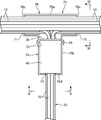
- FIG. 3 is a view showing a cross section taken along line III-III in FIG. 2.
- FIG. 4 is a view showing a cross section taken along line IV-IV in FIG. 2.
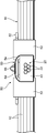
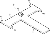
- FIG. 4 is a perspective view of the connector protection member which comprises the wire harness shown by FIG. It is a bottom view of the connector protection member. It is a side view of the said connector protection member. It is a perspective view which shows the principal part of the wire harness which concerns on the 2nd Embodiment of this invention.
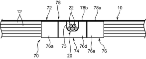
- FIG. 10 is a view showing a cross section taken along line XX of FIG. 9.
- FIG. 10 is a view showing a cross section taken along line XI-XI in FIG. 9; It is a perspective view of the harness protector.
- the wire harness includes a main line harness 10, a branch line harness 20, a main line connector 30, a branch line connector 40, and a connector protector 50.
- the trunk harness 10 includes a plurality of electric wires 12 that are bundled together.
- the branch harness 20 includes a plurality of electric wires 22 bundled with each other, and can be connected to the main line harness 10 so as to branch from an intermediate portion of the main line harness 10.
- the main line connector 30 is provided in the middle part of the main line harness. Specifically, the main line connector 30 is provided at the end of the electric wire 12 to be branched and connected to the branch line harness 20 among the electric wires 12 included in the main line harness 10.
- the main line connector 30 has a plurality of connector terminals that are respectively attached to the ends of the electric wires 12 to be branched and a connector housing that holds these connector terminals. Of these, only the connector housing is illustrated in FIG. 1 to 4 are shown.
- the branch line connector 40 is provided at one end of the branch line harness 20 at a base end part to be connected to the main line harness 10, and is included in the main line harness 10 by being coupled to the main line connector 30.
- the branch connection target electric wires 12 and the electric wires 22 included in the branch harness 20 are electrically connected to each other.
- the branch line connector 40 has a plurality of connector terminals respectively attached to the ends of the plurality of electric wires 22, and a connector housing for holding these connector terminals, and only the connector housing is shown in FIGS. 4.
- various devices to be connected to the end of the wire harness are connected to the distal end which is the other end of the branch harness 20.
- the connector protector 50 is for protecting the trunk line connector 30 and the branch line connector 40 from a load acting on the branch line harness 20, particularly a tensile load indicated by an arrow At in FIG.
- the connector protection member 60 is made of a single plate material, and integrally includes a main line side connecting portion 62 and a branch line side connecting portion 64.
- the main line side connecting portion 62 is a portion that is connected to and fixed to the main line harness 10 and has a shape that extends along the longitudinal direction of the main line harness 10.
- the main line side connecting portion 62 according to this embodiment has a substantially rectangular shape having a certain width in a direction orthogonal to the longitudinal direction of the main line harness 10.
- the branch line side connecting portion 64 is a portion that is connected and fixed to the branch line connector 40, and in this embodiment, the branch line side connecting portion 64 is branched in the longitudinal direction so as to branch from the middle portion in the longitudinal direction of the main line side connecting portion 62. It extends in the direction orthogonal to the direction.
- the branch line side connecting portion 64 also has a substantially rectangular shape having a certain width in a direction orthogonal to the longitudinal direction of the branch line side connecting portion 64, similarly to the main line side connecting portion 62.
- the branch line side connecting part 64 and the branch line connector 40 further have engaging parts 66 and 46 as shown in FIG. These engaging portions 66 and 46 are engaged with each other, so that the branch connector 40 is relatively displaced in the direction in which the branch connector 40 is separated from the main line side connecting portion 62 (downward in FIGS. 2 and 3).
- the engaging portion 66 of the branch line side connecting portion 64 has a shape that protrudes toward the branch line connector 40 on the surface (back surface) of the branch line side connecting portion 64 that faces the branch line connector 40.
- the engaging portion 46 of the branch line connector 40 has a recessed shape so as to accept the fitting of the engaging portion 66 on the outer surface of the connector housing of the branch line connector 40 that faces the branch line side connecting portion 64.
- the connector protector 50 further includes a main line binding tool 52 and a branch line binding tool 54.
- the trunk wire tying member 52 is made of, for example, an adhesive tape, and sandwiches a predetermined portion of the trunk line side coupling portion 62, in this embodiment, a central portion of the trunk line side coupling portion 62 connected to the branch line side coupling portion 64. It winds around the said trunk line harness 10 so that it may be stuck ranging over the site
- the main line tying member 52 binds the main line harness 10 and the main line side connecting portion 62, thereby fixing the main line side connecting portion 62 to the main line harness 10.
- the branch line tying member 54 is also made of, for example, an adhesive tape having a certain width, and is connected to the branch line side connecting portion 64 and the branch line connector 44 in a state where the engaging portions 66 and 46 are engaged with each other. It is wound so as to be attached to the branch line side connecting portion 64 and the branch line connector 44 across the bridge.
- the branch line binding tool 54 binds the branch line side connecting portion 64 and the branch line connector 40, thereby fixing the branch line side connecting portion 64 to the branch line connector 40.
- Each of the binding tools 52 and 54 can be constituted by a binding tool other than the adhesive tape, for example, a binding band that does not have an adhesive force but has a strong clamping force.
- positioning protrusions 63 are formed that protrude to both outer sides in the width direction from other portions. These positioning projections 63 are for regulating the position of the outer end of the trunk line tying member 54 wound around the trunk line side connecting portion 62.
- the connector protection member 60 has a fixed portion 68 for fixing to an appropriate part of a vehicle on which the wire harness is mounted, for example, a car body.
- the fixed portion 68 protrudes from the central part of the main line side connecting part 62, that is, the part where the main line side connecting part 62 and the branch line side connecting part 64 branch, to the front side (the side opposite to the main line harness 10), By being press-fitted into a hole provided in the vehicle, the vehicle is connected to the vehicle.
- the connection of the fixed portion 68 provided in the branch portion to the vehicle enables both the main line harness 10 and the branch line harness 20 to be effectively fixed to the vehicle.
- the fixed portion 68 can be omitted as appropriate in the present invention.
- the wire harness described above includes, for example, a step of preparing the main line harness 10 to which the main line connector 30 is attached and the branch line harness 20 to which the branch line connector 40 is attached, and the main line connector 30 and the branch line. Connecting the connector 40 to electrically connect the electric wire 12 included in the main line harness 10 and the electric wire 22 included in the branch line harness 20, and the main line side connecting portion 62 and the branch line side of the connector protection member 60; It is possible to manufacture the connecting portion 64 by connecting and fixing the connecting portion 64 to the main harness 10 and the branch connector 40 using the main wire binding device 52 and the branch wire binding device 54, respectively.
- the main line harness 10 and the branch line harness 20 are divided, for example, the main line harness 10 is used in common while the branch line harness 20 is used in accordance with the type of equipment connected to the same.
- the wire harness can be diversified at low cost.
- assembly is easier as compared with a wire harness integrated as a whole.
- connection part of the said trunk line harness 10 and the branch line harness 20 ie, the part in which the trunk line connector 30 and the branch line connector 40 for connecting both are provided, is set to the branch part which is easy to receive a big load.
- the connector protection member 60 is disposed and fixed across the main line harness 10 and the branch line connector 40, so that the main line connector 30 and the branch line connector 40 against the load acting on the branch line harness 20. It is possible to regulate the relative displacement. For example, regardless of the tensile load applied to the branch harness 20, it is possible to maintain a state in which an appropriate extra length is given to the electric wire connected to the main connector 30 in the main harness 10. Thereby, it is possible to suppress the wear of the contact portion due to the relative displacement between the two connectors 30 and 40 and to prevent the connectors 30 and 40 from being separated from each other.
- the main line side connecting portion 62 of the connector protection member 60 since the main line side connecting portion 62 of the connector protection member 60 has a shape extending along the longitudinal direction of the main line harness 10, in a stable state on the outer peripheral surface of the main line harness 10. It can be fixed.
- the branch line connector 64 with respect to the main line harness 10 is connected to the branch line connector 40 by connecting the branch line side connection part 64 extending in a predetermined branching direction from the main line side connection part 62 while being integrally connected to the main line side connection part 62. The relative displacement of 40 can be suppressed more effectively.
- the engagement between the engaging portions 66, 46 provided in the branch line side connecting portion 64 and the branch line connector 40 is caused by relative displacement of the branch line connector 40 with respect to the branch line side connecting portion 64, and consequently the branch line connector 40 with respect to the main line harness 10.
- the relative displacement of the connectors 30 and 40 can be more reliably suppressed, and thereby the protection effect of the connectors 30 and 40 can be further enhanced.
- This wire harness has the trunk line harness 10, the branch line harness 20, the trunk line connector 30, and the branch line connector 40 equivalent to the trunk line harness 10, the branch line harness 20, the trunk line connector 30 and the branch line connector 40 according to the first embodiment.
- a harness protector 70 as shown in FIG. 12 is provided instead of the connector protector 50 according to the first embodiment.
- the harness protector 70 covers the branch portion including both the connectors 30 and 40 from the outside in the wire harness, thereby protecting the branch portion (preventing contact with other members) and the first protector. Similar to the connector protector 50 according to the embodiment, it functions as a connector protection member that restricts the relative displacement between the connectors 30 and 40.
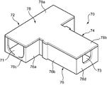
- the harness protector 70 integrally includes a main line harness accommodating portion 72 and a branch line harness accommodating portion 74.
- the trunk harness accommodating portion 72 is a portion that accommodates at least a portion of the trunk harness 10 that includes a branch portion connected to the trunk connector 30.
- the main harness harness 72 according to this embodiment has a rectangular tube shape that covers the outer peripheral surface of the main harness 10.
- the branch harness housing part 74 is a part that houses the branch line connector 40 and the main line connector 30 coupled to the branch line connector 40 so as to restrain the branch line connector 40.
- the branch line harness housing part 72 is provided. It extends so as to diverge from the middle part in the longitudinal direction, and forms a rectangular tube shape covering the connectors 30 and 40.
- the harness protector 70 is divided into a protector body 76 and a lid 78.
- the protector body 76 has a container shape whose upper end surrounds the opening.
- the lid 78 is attached to the protector 76 so as to close the opening of the protector main body 76, thereby configuring the trunk harness housing portion 72 and the connector housing portion 74 in cooperation with the protector body 76.
- the protector body 76 integrally includes a first side wall 76a, a first end wall 76c, a second side wall 76b, and a second end wall 76d.
- the first side wall portion 76 a constitutes a bottom wall and both side walls of the peripheral wall of the main line harness housing portion 72.
- the first end wall portion 76 c constitutes both end walls of the trunk harness housing portion 72.
- the second side wall portion 76 b constitutes a bottom wall and both side walls of the peripheral wall of the connector housing portion 74.
- the second end wall portion 76d constitutes a terminal wall of the connector housing portion 74, that is, an end wall on the opposite side to the main wire harness housing portion 72.
- Both the first end wall portions 76c have a notch 71 having a shape that opens upward, and the notch 71 has a shape that allows the main line harness 10 to pass through the notch 71.
- both the second end wall portions 76d have a notch 73 that opens upward, and the notch 73 has a shape that allows the branch harness 20 connected to the branch connector 40 to pass through the notch 73.
- the lid 78 integrally includes a first lid plate portion 78a and a second lid plate portion 78b.
- the first lid plate portion 78a has a rectangular plate shape that closes an opening surrounded by an upper end of the first side wall portion 76a of the protector body 76.
- the first cover plate portion 78a is joined to the upper end of the first side wall portion 76a, thereby constituting a peripheral wall of the main harness housing portion 72 in cooperation with the first side wall portion 76a. Further, both ends in the longitudinal direction of the first lid plate portion 78a, together with the first end wall portion 76c, restrain the trunk harness 10 from outside with an appropriate restraining force.
- the second lid plate portion 78b extends from an intermediate portion in the longitudinal direction of the first lid plate portion 78a, and has a rectangular plate shape that closes an opening surrounded by an upper end of the second side wall portion 76b of the protector body 76. Eggplant.
- the second cover plate portion 78b is joined to the upper end of the second side wall portion 76b, thereby constituting the peripheral wall of the connector housing portion 74 in cooperation with the second side wall portion 76b.
- the second end wall portion 76d of the protector main body 76 restrains the branch line connector 40 from the side opposite to the main line harness 10 (the lower side in FIG. 9), so that the branch line connector 40 is connected to the main line harness 10.
- the branch line connector 40 has a function of regulating relative displacement in a direction away from the main harness 10.
- the outer surface of the branch line connector 40 includes a connector side fitting portion 45 that protrudes in a direction orthogonal to the longitudinal direction of the branch line harness 20, while the connector housing portion 74.
- the protector side fitting part 75 which is recessed so that the inner surface of the 2nd side wall part 76b which comprises may be fitted with the said connector side fitting part 45 is included. The fitting between the fitting portions 45 and 75 surely regulates the relative displacement of the branch line connector 40 with respect to the harness protector 70, particularly the displacement in the direction in which the branch line connector 40 is separated from the main line harness 10.
- the wire harness according to the second embodiment described above includes, for example, the step of preparing the trunk line harness 10 to which the trunk line connector 30 is attached and the branch line harness 20 to which the branch line connector 40 is attached, The step of connecting the main line connector 30 and the branch line connector 40 to electrically connect the electric wire 12 included in the main line harness 10 and the electric wire 22 included in the branch line harness 20, and accommodating the main line harness of the harness protector 70
- the main line harness 10 and the connectors 30 and 40 are accommodated in the part 72 and the connector accommodating part 74, respectively, and the main line harness accommodating part 72 corresponding to the main line side connecting part is connected to the main line harness 10 by restraining each.
- the connector housing portion 74 corresponding to the branch line side connecting portion is connected to the branch line connector 40. It is possible to be produced and a step of forming, by.
- the main line harness accommodating portion 72 and the connector accommodating portion 74 of the harness protector 70 accommodate the main line harness 10 and both connectors 30 and 40 while restraining the main line connector 30 connected to the main line harness 10.
- the main line harness 10 accommodated in the connector accommodating portion 74, the main line harness 10, the main line connector 30, and the contact between the branch line connector 40 and other members outside the harness protector 70. To ensure these protections.
- the specific shape of the connector protection member according to the present invention is not limited to the connector protection member 60 or the harness protector 70.
- the branch line side connecting portions according to the present invention extend integrally from the respective tie bands and are connected to the left and right side surfaces of the branch connector 40, respectively. It may be done.
- connection mode between the connector protection member, the main harness and the branch connector is not limited.
- the connector protection member may be formed integrally with the connector housing of the branch line connector.
- the provided wire harness includes a trunk harness including a plurality of electric wires bundled together, a branch harness including a plurality of electric wires bundled together and connectable to the trunk harness so as to branch from a middle portion of the trunk harness,
- the main line connector provided in the middle part of the main line harness, and the electric wire included in the main line harness and the electric wire included in the branch line harness by being connected to the main line connector provided at an end of the branch line harness.
- the said connector protector contains the connector protection member arrange
- the connector protection member includes a main line side connection portion connected and fixed to the main line harness, and a branch line side connection portion connected and fixed to the branch line connector, the main line side connection portion and the branch line side connection portion.
- the main line side connecting part and the branch line side connecting part are integrally connected so as to fix the relative position between the main line connector and the branch line connector against a load acting on the branch line harness. regulate.
- the main line side connecting part and the branch line side connecting part of the connector protection member are connected and fixed to the main line harness and the branch line connector, in other words, the branch line connector is protected by the connector.
- the relative displacement between the branch line connector provided in the branch line harness and the main line connector provided in the main line harness is regulated regardless of the load acting on the branch line harness.
- the main line side connection portion of the connector protection member extends along the longitudinal direction of the main wire harness
- the branch line side connection portion extends from the middle portion of the main line side connection portion to the branch line connector and What extends in the direction toward the branch line harness is suitable.
- the connector protector is wound around the main line harness across the main line side connecting part and the outer peripheral surface of the main line harness so as to fix the main line side connecting part to the main line harness.
- a branch line binding tool for binding the branch line side connecting portion and the branch line connector so as to fix the connector.
- the main line binding tool and the branch line binding tool are capable of stably fixing the main line side connecting part extending along the longitudinal direction of the main line harness to the main line harness, and further, the main line side connecting part.
- the branch line side coupling portion and the branch line connector are engaged with each other so as to regulate relative displacement of the branch line connector in a direction in which the branch line connector is separated from the main line side coupling portion. It is preferable to have each.
- the engagement between the engaging portions makes it possible to more reliably prevent relative displacement between the branch line connector and the main line connector coupled thereto, thereby enabling more effective protection of both connectors.
- the connector protector includes a harness protector as the connector protection member, and the harness protector accommodates the main wire harness while restraining at least a portion including a branch portion connected to the main line connector of the main line harness.
- the branch line connector and a connector housing portion that houses the main line connector coupled to the branch line connector so as to restrain the branch line connector may be integrally provided.
- the main line harness accommodating portion and the connector accommodating portion accommodate the main line harness and both connectors while constraining the main line harness and the connectors, respectively, and thereby the main line connector connected to the main line harness and the branch line accommodated in the connector accommodating portion.
- the main line harness, the main line connector and the branch line connector are prevented from coming into contact with other members outside the harness protector, thereby further ensuring their protection. .
- the outer side surface of the branch line connector includes a connector side fitting portion that protrudes or dents in a direction orthogonal to the longitudinal direction of the branch line harness, and the inner side surface of the connector housing portion is fitted with the connector side fitting portion.
- the branch line connector includes a protector-side fitting portion that restricts relative displacement in a direction away from the trunk harness. The fitting between the connector-side fitting portion and the protector-side fitting portion more reliably prevents relative displacement between the branch line connector and the main line connector coupled thereto, thereby protecting both connectors more effectively. Make it possible to do.
- the provided method is a main line harness in which a plurality of electric wires are bundled, and a branch line harness in which a plurality of electric wires are bundled, and can be branched from the main line harness by being connected to a middle portion of the main line harness.
- the manufacturing method by dividing the main line harness and the branch line harness from each other, the combination of the main line harness and the branch line harness can be diversified, and the assembly of the entire wire harness can be facilitated.
- the relative displacement between the main line connector connected to the main line harness and the branch line connector is regulated by connecting the main line harness and the branch line connector connected to the branch line harness via a connector protection member. It is possible to effectively suppress the contact portion resulting from the above and to prevent the connectors from being separated.
Landscapes
- Engineering & Computer Science (AREA)
- Manufacturing & Machinery (AREA)
- Mechanical Engineering (AREA)
- Architecture (AREA)
- Civil Engineering (AREA)
- Structural Engineering (AREA)
- Details Of Indoor Wiring (AREA)
- Insulated Conductors (AREA)
Abstract
幹線部分と支線部分とが分割されかつその分割部分の保護が可能なワイヤハーネスとその製造方法が提供される。ワイヤハーネスは、幹線ハーネス10と、支線ハーネス20と、幹線ハーネス10の途中部分に設けられる幹線コネクタ30と、支線ハーネス20の端部に設けられて幹線コネクタ30と結合可能な支線コネクタ40と、コネクタ保護具50と、を備える。コネクタ保護具50は、幹線ハーネス10と支線コネクタ40とに跨るコネクタ保護部材60を含む。コネクタ保護部材60は、幹線ハーネス10に連結される幹線側連結部62と、支線コネクタ40に連結される支線側連結部64と、を含み、両連結部62,64が一体につながることにより、コネクタ30,40同士の相対変位を規制する。
Description
本発明は、互いに分割された複数の部分を有してその分割された部分同士がコネクタを介して結合されるワイヤハーネス及びその製造方法に関する。
近年、ワイヤハーネスの大型化、複雑化に伴い、当該ワイヤハーネスを分割してその分割された部分同士をコネクタにより相互接続する技術が、検討されている。例えば特許文献1には、自動車に搭載されるワイヤハーネスを複数のサブハーネスに分割し、その分割されたサブハーネス同士をコネクタを介して接続する技術が、開示されている。
本発明者らは、前記ワイヤハーネスの組立の合理化に適した分割箇所として、その幹線部と支線部との接続箇所である分岐部に着目した。この分岐部において当該幹線部と当該支線部とを分割することは、例えば、前記幹線部には共通のものを使用しながら、端末の機器に接続される支線部を当該機器の種類やグレードに応じて適宜変更することにより、様々な車種や仕様に対応した複数種のワイヤハーネスを低コストで合理的に構築することが可能になる。
しかしながら、前記分岐部には、ワイヤハーネスの搭載時に前記支線部に与えられる張力や、車両走行時における幹線部と支線部との相対変位等に起因して大きな荷重が作用しやすく、このことは、当該分岐部を分割箇所に選定すること、すなわち、前記幹線部と前記支線部とを分割して両者に設けられたコネクタ同士を前記分岐部にて結合すること、を困難にする。具体的に、当該分岐部に互いに嵌合するコネクタ(幹線側のコネクタ及び支線側のコネクタ)を配置した場合、当該分岐部に作用する前記の大きな荷重は幹線側のコネクタと支線側のコネクタとを相対変位させることにより当該コネクタにおいて互いに嵌合する端子同士に微小な相対変位を発生させ、これにより当該端子の接点の摩耗を促進し、最悪の場合にはコネクタ同士を分離させるおそれがある。
本発明は、幹線部分と支線部分とが相互に分割されたワイヤハーネスであってその分割部分が大きな荷重から有効に保護されることが可能なものを提供することを目的とする。
本発明により提供されるワイヤハーネスは、互いに束ねられる複数の電線を含む幹線ハーネスと、互いに束ねられる複数の電線を含み、前記幹線ハーネスの途中部分から分岐するように当該幹線ハーネスに接続可能な支線ハーネスと、前記幹線ハーネスの途中部分に設けられる幹線コネクタと、前記支線ハーネスの端部に設けられて前記幹線コネクタと結合することにより前記幹線ハーネスに含まれる前記電線と前記支線ハーネスに含まれる前記電線とを相互に電気的に接続する支線コネクタと、前記支線ハーネスに作用する荷重から前記幹線コネクタ及び前記支線コネクタを保護するためのコネクタ保護具と、を備える。前記コネクタ保護具は、前記幹線ハーネスと前記支線コネクタとに跨るように配置されるコネクタ保護部材を含む。このコネクタ保護部材は、前記幹線ハーネスに連結され固定される幹線側連結部と、前記支線コネクタに連結され固定される支線側連結部と、を含み、前記幹線側連結部と前記支線側連結部との相対位置を固定するように当該幹線側連結部と当該支線側連結部とが一体につながることにより、前記支線ハーネスに作用する荷重に抗して前記幹線コネクタと前記支線コネクタの相対変位を規制する。
本発明の好ましい実施の形態を、図面を参照しながら説明する。
図1~図4は、本発明の第1の実施の形態に係るワイヤハーネスの要部を示す。このワイヤハーネスは、幹線ハーネス10と、支線ハーネス20と、幹線コネクタ30と、支線コネクタ40と、コネクタ保護具50と、を備える。
前記幹線ハーネス10は、互いに束ねられる複数の電線12を含む。前記支線ハーネス20は、互いに束ねられる複数の電線22を含み、前記幹線ハーネス10の途中部分から分岐するように当該幹線ハーネス10に接続されることが可能である。
前記幹線コネクタ30は、前記幹線ハーネスの途中部分に設けられる。詳しくは、当該幹線コネクタ30は、前記幹線ハーネス10に含まれる電線12のうち前記支線ハーネス20に分岐接続されるべき電線12の端末に設けられる。幹線コネクタ30は、当該分岐接続の対象となる電線12の端末にそれぞれ装着される複数のコネクタ端子と、これらのコネクタ端子を保持するコネクタハウジングと、を有し、このうち当該コネクタハウジングのみが図1~図4に示されている。
前記支線コネクタ40は、前記支線ハーネス20の一方の端部であって前記幹線ハーネス10に接続されるべき基端部に設けられ、前記幹線コネクタ30と結合することにより、前記幹線ハーネス10に含まれる分岐接続対象電線12と、前記支線ハーネス20に含まれる電線22とを相互に電気的に接続する。この支線コネクタ40は、前記複数の電線22の端末にそれぞれ装着される複数のコネクタ端子と、これらのコネクタ端子を保持するコネクタハウジングと、を有し、このうち当該コネクタハウジングのみが図1~図4に示されている。一方、前記支線ハーネス20の他方の端部である先端部には、ワイヤハーネスの端末に接続されるべき各種機器が接続される。
前記コネクタ保護具50は、前記支線ハーネス20に作用する荷重、特に図1において矢印Atで示される引張荷重、から前記幹線コネクタ30及び前記支線コネクタ40を保護するためのものであって、前記幹線ハーネス10と前記支線コネクタ40とに跨るように配置されるコネクタ保護部材60を含む。
この実施の形態に係る前記コネクタ保護部材60は、図5~図7に示すように、単一の板材からなり、幹線側連結部62と、支線側連結部64と、を一体に有する。
前記幹線側連結部62は、前記幹線ハーネス10に連結され、固定される部分であり、当該幹線ハーネス10の長手方向に沿って延びる形状を有する。この実施の形態に係る幹線側連結部62は、前記幹線ハーネス10の長手方向と直交する方向に一定の幅を有する略矩形状をなす。
前記支線側連結部64は、前記支線コネクタ40に連結され、固定される部分であり、前記幹線側連結部62の長手方向の途中部分から分岐するように、この実施の形態では当該長手方向に対して直交する方向に、延びている。この支線側連結部64も、前記幹線側連結部62と同様、当該支線側連結部64の長手方向と直交する方向に一定の幅を有する略矩形状をなす。
この実施の形態に係る支線側連結部64及び支線コネクタ40は、さらに、図3に示すような係合部66,46をそれぞれ有する。これらの係合部66,46は、互いに係合することにより、前記幹線側連結部62に対して前記支線コネクタ40が離れる向き(図2及び図3では下向き)に当該支線コネクタ40が相対変位することを規制する。具体的に、前記支線側連結部64の係合部66は、当該支線側連結部64のうち前記支線コネクタ40に対向する面(裏面)において当該支線コネクタ40に向かって突出する形状を有する。前記支線コネクタ40の係合部46は、当該支線コネクタ40のコネクタハウジングの外側面のうち前記支線側連結部64に対向する面において前記係合部66の嵌まり込みを受け入れるように凹んだ形状を有する。
前記コネクタ保護具50は、さらに、幹線用結束具52及び支線用結束具54を有する。前記幹線用結束具52は、例えば粘着テープからなり、前記幹線側連結部62の所定部位、この実施の形態では当該幹線側連結部62のうち前記支線側連結部64とつながる中央部位を挟んでその両側の部位、と前記幹線ハーネス10の外周面とに跨って貼着されるように当該幹線ハーネス10に巻き付けられる。これにより、当該幹線用結束具52は、当該幹線ハーネス10と当該幹線側連結部62とを結束し、これにより当該幹線ハーネス10に当該幹線側連結部62を固定する。同様に、前記支線用結束具54も、例えば一定の幅をもつ粘着テープからなり、前記係合部66,46が互いに係合された状態で前記支線側連結部64と前記支線コネクタ44とに跨って当該支線側連結部64及び当該支線コネクタ44に貼着されるように巻き付けられる。これにより、当該支線用結束具54は、当該支線側連結部64と当該支線コネクタ40とを結束し、これにより当該支線側連結部64を当該支線コネクタ40に固定する。前記各結束具52,54は、粘着テープ以外の結束具、例えば粘着力は有しないが強い締め付け力をもつ結束バンド、によっても構成されることが可能である。
前記幹線側連結部62の長手方向の両端には、他の部分よりも幅方向の両外側にそれぞれ突出する位置決め用突起63が形成されている。これらの位置決め用突起63は、前記幹線側連結部62に巻き付けられる前記幹線用結束具54の外側端の位置を規制するためのものである。
また、この実施の形態に係る前記コネクタ保護部材60は、前記ワイヤハーネスが搭載される車両の適当な部位、例えばカーボディ、に固定されるための被固定部68を有する。この被固定部68は、前記幹線側連結部62の中央部位、つまり幹線側連結部62と支線側連結部64とが分岐する部位、から表側(幹線ハーネス10と反対の側)に突出し、前記車両に設けられた穴に圧入されることにより、当該車両に連結される。このような分岐部に設けられた被固定部68の車両への連結は、幹線ハーネス10と支線ハーネス20の双方を車両に効果的に固定することを可能にする。この被固定部68は、本発明においては適宜省略が可能である。
以上説明したワイヤハーネスは、例えば、前記幹線コネクタ30が取付けられた前記幹線ハーネス10と、前記支線コネクタ40が装着された前記支線ハーネス20と、を用意する工程と、前記幹線コネクタ30と前記支線コネクタ40とを結合して前記幹線ハーネス10に含まれる電線12と前記支線ハーネス20に含まれる電線22とを電気的に接続する工程と、前記コネクタ保護部材60の幹線側連結部62及び支線側連結部64をそれぞれ前記幹線用結束具52及び前記支線用結束具54を用いて前記幹線ハーネス10及び前記支線コネクタ40に連結して固定する工程と、によって製造されることが、可能である。
このワイヤハーネスによれば、幹線ハーネス10と支線ハーネス20とが分割されているので、例えば幹線ハーネス10には共通のものを用いながら支線ハーネス20をこれに接続される機器の種類等に応じて適宜変更することにより、低コストで当該ワイヤハーネスの多様化が可能である。また、全体が一体化されたワイヤハーネスに比べて組立も容易である。
しかも、前記幹線ハーネス10と支線ハーネス20との接続部位、つまり両者を接続するための幹線コネクタ30及び支線コネクタ40が設けられる部位、が大きな荷重を受けやすい分岐部分に設定されているにもかかわらず、当該幹線ハーネス10と当該支線コネクタ40とに跨ってコネクタ保護部材60が配設され、固定されることにより、前記支線ハーネス20に作用する荷重に抗して幹線コネクタ30と支線コネクタ40との相対変位を規制することが可能である。例えば、支線ハーネス20に与えられる引張荷重にかかわらず、幹線ハーネス10において幹線コネクタ30に接続される電線に適当な余長が与えられた状態を保持することが可能である。これにより、前記両コネクタ30,40同士の相対変位に起因する接点部分の摩耗を抑止し、またコネクタ30,40同士の分離を防ぐことができる。
特に、この実施の形態では、前記コネクタ保護部材60の幹線側連結部62が、前記幹線ハーネス10の長手方向に沿って延びる形状を有するので、当該幹線ハーネス10の外周面上に安定した状態で固定されることが可能である。しかも、この幹線側連結部62と一体につながりながら当該幹線側連結部62から所定の分岐方向に延びる支線側連結部64が支線コネクタ40に連結されることにより、前記幹線ハーネス10に対する前記支線コネクタ40の相対変位をより有効に抑止することができる。
さらに、前記支線側連結部64及び支線コネクタ40にそれぞれ設けられた係合部66,46同士の係合は、支線側連結部64に対する支線コネクタ40の相対変位、ひいては幹線ハーネス10に対する支線コネクタ40の相対変位、をより確実に抑止し、これによりコネクタ30,40の保護効果を一層高めることができる。
図8~図11は、本発明の第2の実施の形態に係るワイヤハーネスの要部を示す。このワイヤハーネスは、第1の実施の形態に係る幹線ハーネス10、支線ハーネス20、幹線コネクタ30及び支線コネクタ40と同等の幹線ハーネス10、支線ハーネス20、幹線コネクタ30及び支線コネクタ40を有するとともに、当該第1の実施の形態に係るコネクタ保護具50に代えて図12にも示すようなハーネスプロテクタ70を備える。
このハーネスプロテクタ70は、前記ワイヤハーネスにおいて前記両コネクタ30,40を含む分岐部分を外側から覆うことにより、当該分岐部分の保護(他の部材との接触の防止)を行いながら、前記第1の実施の形態に係るコネクタ保護具50と同様に両コネクタ30,40同士の相対変位を規制するコネクタ保護部材として機能する。
このハーネスプロテクタ70は、幹線ハーネス収容部72と、支線ハーネス収容部74と、を一体に有する。前記幹線ハーネス収容部72は、前記幹線ハーネス10のうち少なくとも前記幹線コネクタ30につながる分岐部を含む部分を拘束しながら収容する部分である。この実施の形態に係る幹線ハーネス収容部72は、前記幹線ハーネス10の外周面を覆う角筒状をなす。前記支線ハーネス収容部74は、前記支線コネクタ40を拘束するように当該支線コネクタ40及びこれに結合される前記幹線コネクタ30を収容する部分であり、この実施の形態では、前記幹線ハーネス収容部72の長手方向の途中部分から分岐するように延びて前記コネクタ30,40を覆う角筒状をなす。
この実施の形態に係るハーネスプロテクタ70は、プロテクタ本体76と、蓋78と、に分割されている。プロテクタ本体76は、上端が開口を囲む容器状をなす。前記蓋78は当該プロテクタ本体76の開口を塞ぐように当該プロテクタ76に装着され、これにより、当該プロテクタ本体76と協働して前記幹線ハーネス収容部72及び前記コネクタ収容部74を構成する。
前記プロテクタ本体76は、第1側壁部76aと、第1端壁部76cと、第2側壁部76bと、第2端壁部76dと、を一体に有する。前記第1側壁部76aは、前記幹線ハーネス収容部72の周壁のうちの底壁及び両側壁を構成する。前記第1端壁部76cは、当該幹線ハーネス収容部72の両端壁を構成する。前記第2側壁部76bは、前記コネクタ収容部74の周壁のうちの底壁及び両側壁を構成する。前記第2端壁部76dは、当該コネクタ収容部74の終端壁すなわち前記幹線ハーネス収容部72と反対側の端壁を構成する。前記両第1端壁部76cは上向きに開く形状の切欠71を有し、この切欠71は当該切欠71を前記幹線ハーネス10が貫通することを許容する形状を有する。同様に、前記両第2端壁部76dは上向きに開く形状の切欠73を有し、この切欠73は当該切欠73を前記支線コネクタ40につながる前記支線ハーネス20が貫通することを許容する形状を有する。
前記蓋78は、第1蓋板部78aと第2蓋板部78bとを一体に有する。前記第1蓋板部78aは、前記プロテクタ本体76の第1側壁部76aの上端が囲む開口を塞ぐ矩形板状をなす。当該第1蓋板部78aは、当該第1側壁部76aの上端に接合されることにより、当該第1側壁部76aと協働して前記幹線ハーネス収容部72の周壁を構成する。さらに、当該第1蓋板部78aの長手方向の両端は、前記第1端壁部76cとともに、前記幹線ハーネス10を外側から適当な拘束力で拘束する。前記第2蓋板部78bは、前記第1蓋板部78aの長手方向の中間部分から分岐するように延び、前記プロテクタ本体76の第2側壁部76bの上端が囲む開口を塞ぐ矩形板状をなす。当該第2蓋板部78bは、当該第2側壁部76bの上端に接合されることにより、当該第2側壁部76bと協働して前記コネクタ収容部74の周壁を構成する。
また、前記プロテクタ本体76の第2端壁部76dは、前記支線コネクタ40を前記幹線ハーネス10と反対の側(図9では下側)から拘束することにより当該支線コネクタ40が幹線ハーネス10に対して当該幹線ハーネス10から離れる向きの相対変位を規制する機能を有する。
さらに、この実施の形態に係るハーネスプロテクタ70では、前記支線コネクタ40の外側面が前記支線ハーネス20の長手方向と直交する方向に突出するコネクタ側嵌合部45を含む一方、前記コネクタ収容部74を構成する第2側壁部76bの内側面が前記コネクタ側嵌合部45と嵌合するように凹むプロテクタ側嵌合部75を含む。当該嵌合部45,75同士の嵌合は、ハーネスプロテクタ70に対する支線コネクタ40の相対変位、特に当該支線コネクタ40が幹線ハーネス10から離れる向きの変位、を確実に規制する。この効果は、前記嵌合部45,75の凹凸が逆である場合、すなわち、前記コネクタ側嵌合部45が凹部であって前記プロテクタ嵌合部75が当該凹部に嵌まり込む凸部である場合、にも成立する。
以上説明した第2の実施の形態に係るワイヤハーネスは、例えば、前記幹線コネクタ30が取付けられた前記幹線ハーネス10と、前記支線コネクタ40が装着された前記支線ハーネス20を用意する工程と、前記幹線コネクタ30と前記支線コネクタ40とを結合して前記幹線ハーネス10に含まれる電線12と前記支線ハーネス20に含まれる電線22とを電気的に接続する工程と、前記ハーネスプロテクタ70の幹線ハーネス収容部72及びコネクタ収容部74にそれぞれ幹線ハーネス10及びコネクタ30,40を収容してそれぞれを拘束することにより、幹線側連結部に相当する前記幹線ハーネス収容部72を前記幹線ハーネス10に連結するとともに支線側連結部に相当する前記コネクタ収容部74を前記支線コネクタ40に連結する工程と、によって製造されることが、可能である。
このワイヤハーネスでは、前記ハーネスプロテクタ70の幹線ハーネス収容部72及びコネクタ収容部74がそれぞれ幹線ハーネス10及び両コネクタ30,40を拘束しながら収容することにより、前記幹線ハーネス10につながる幹線コネクタ30と前記コネクタ収容部74に収容される支線コネクタ40との相対変位を有効に規制するのに加え、前記幹線ハーネス10、幹線コネクタ30及び支線コネクタ40とハーネスプロテクタ70の外部の他の部材との接触を阻止してこれらの保護をより確実にする。
本発明に係るコネクタ保護部材の具体的な形状は、前記コネクタ保護部材60や前記ハーネスプロテクタ70に限定されない。例えば、図1に示される両幹線用結束具52が結束バンドである場合、本発明に係る支線側連結部は、当該各結束バンドと一体にこれから延びて支線コネクタ40の左右両側面にそれぞれ連結されるものであってもよい。
また、前記コネクタ保護部材と幹線ハーネス及び支線コネクタとの具体的な連結態様は限定されない。例えば、当該コネクタ保護部材は当該支線コネクタのコネクタハウジングと一体に成形されたものでもよい。
以上のように、幹線部分と支線部分とが相互に分割されたワイヤハーネスであってその分割部分が大きな荷重から有効に保護されることが可能なもの、及び当該ワイヤハーネスを製造する方法、が提供される。
提供されるワイヤハーネスは、互いに束ねられる複数の電線を含む幹線ハーネスと、互いに束ねられる複数の電線を含み、前記幹線ハーネスの途中部分から分岐するように当該幹線ハーネスに接続可能な支線ハーネスと、前記幹線ハーネスの途中部分に設けられる幹線コネクタと、前記支線ハーネスの端部に設けられて前記幹線コネクタと結合することにより前記幹線ハーネスに含まれる前記電線と前記支線ハーネスに含まれる前記電線とを相互に電気的に接続する支線コネクタと、前記支線ハーネスに作用する荷重から前記幹線コネクタ及び前記支線コネクタを保護するためのコネクタ保護具と、を備える。前記コネクタ保護具は、前記幹線ハーネスと前記支線コネクタとに跨るように配置されるコネクタ保護部材を含む。このコネクタ保護部材は、前記幹線ハーネスに連結され固定される幹線側連結部と、前記支線コネクタに連結され固定される支線側連結部と、を含み、前記幹線側連結部と前記支線側連結部との相対位置を固定するように当該幹線側連結部と当該支線側連結部とが一体につながることにより、前記支線ハーネスに作用する荷重に抗して前記幹線コネクタと前記支線コネクタの相対変位を規制する。
このワイヤハーネスによれば、前記コネクタ保護部材の幹線側連結部及び支線側連結部が前記幹線ハーネス及び前記支線コネクタにそれぞれ連結されて固定されること、換言すれば、前記支線コネクタが前記コネクタ保護部材を介して前記幹線ハーネスに連結されること、により、当該支線ハーネスに作用する荷重にかかわらず当該支線ハーネスに設けられる前記支線コネクタと前記幹線ハーネスに設けられる幹線コネクタとの相対変位を規制することができ、これにより、当該相対変位に起因する前記両コネクタでの接点の摩耗を抑止し、またコネクタ同士の分離を確実に防ぐことができる。
前記コネクタ保護部材は、例えば、前記コネクタ保護部材の幹線側連結部が、前記幹線ハーネスの長手方向に沿って延び、前記支線側連結部が、前記幹線側連結部の途中部分から前記支線コネクタ及び支線ハーネスに向かう方向に延びるものが、好適である。この場合、前記コネクタ保護具は、前記幹線側連結部と前記幹線ハーネスの外周面とに跨って当該幹線ハーネスに巻き付けられることにより当該幹線ハーネスに当該幹線側連結部を固定するように当該幹線ハーネスと当該幹線側連結部を結束する幹線用結束具と、前記支線側連結部と前記支線コネクタとに跨って当該支線側連結部及び当該支線コネクタに巻き付けられることにより当該支線側連結部に当該支線コネクタを固定するように当該支線側連結部と当該支線コネクタとを結束する支線用結束具と、をさらに有するのが、好ましい。当該幹線用結束具及び支線用結束具は、前記幹線ハーネスの長手方向に沿って延びる幹線側連結部を当該幹線ハーネスに安定した状態で固定することが可能であり、さらに、当該幹線側連結部から分岐するように延びる支線側連結部を支線コネクタに固定することによって、前記幹線ハーネスに対する前記支線コネクタの相対変位をより効果的に抑止することができる。
このコネクタ保護具において、前記支線側連結部及び前記支線コネクタは、前記幹線側連結部に対して前記支線コネクタが離れる向きの当該支線コネクタの相対変位を規制するように互いに係合する係合部をそれぞれ有するのが、好ましい。当該係合部同士の係合は、前記支線コネクタとこれに結合される幹線コネクタとの相対変位の阻止をより確実にし、これにより両コネクタをより有効に保護することを可能にする。
前記コネクタ保護具は、あるいは、前記コネクタ保護部材としてハーネスプロテクタを含み、このハーネスプロテクタは、前記幹線ハーネスのうち少なくとも前記幹線コネクタにつながる分岐部を含む部分を拘束しながら収容する幹線ハーネス収容部と、前記支線コネクタを拘束するように当該支線コネクタ及びこれに結合される前記幹線コネクタを収容するコネクタ収容部と、を一体に有するものでもよい。このハーネスプロテクタによれば、前記幹線ハーネス収容部及び前記コネクタ収容部がそれぞれ幹線ハーネス及び両コネクタを拘束しながら収容することにより、前記幹線ハーネスにつながる幹線コネクタと前記コネクタ収容部に収容される支線コネクタとの相対変位を有効に規制するのに加え、前記幹線ハーネス、幹線コネクタ及び支線コネクタがハーネスプロテクタの外部の他の部材と接触するのを阻止してこれらの保護をより確実なものにする。
この場合、前記支線コネクタの外側面は前記支線ハーネスの長手方向と直交する方向に突出または凹むコネクタ側嵌合部を含み、前記コネクタ収容部の内側面は前記コネクタ側嵌合部と嵌合することにより前記支線コネクタが前記幹線ハーネスに対して離れる向きの相対変位を規制するプロテクタ側嵌合部を含むことが、より好ましい。当該コネクタ側嵌合部と当該プロテクタ側嵌合部との嵌合は、前記支線コネクタとこれに結合される幹線コネクタとの相対変位の阻止をより確実にし、これにより両コネクタをより有効に保護することを可能にする。
また、幹線部分と支線部分とが相互に分割されてその分割部分が大きな荷重から有効に保護されることが可能なワイヤハーネスを製造する方法が提供される。
提供される方法は、複数の電線が束ねられた幹線ハーネスと、複数の電線が束ねられた支線ハーネスであって前記幹線ハーネスの途中部分に接続されることにより当該幹線ハーネスから分岐可能なものと、前記幹線ハーネスの途中部分に設けられる幹線コネクタと、前記支線ハーネスの端部に設けられて前記幹線コネクタと結合することにより前記幹線ハーネスと前記支線ハーネスとを相互に電気的に接続する支線コネクタと、を用意する工程と、前記幹線コネクタと前記支線コネクタとを結合して前記幹線ハーネスに含まれる電線と前記支線ハーネスに含まれる電線とを電気的に接続する工程と、前記幹線ハーネスと前記支線コネクタとに跨ることが可能な形状をもつコネクタ保護部材を当該幹線ハーネスと当該支線コネクタとにそれぞれ連結して固定することにより、前記支線ハーネスに作用する荷重に抗して前記幹線コネクタと前記支線コネクタの相対変位を規制する工程と、を含む。
この製造方法によれば、幹線ハーネスと支線ハーネスとを相互に分割することにより、幹線ハーネスと支線ハーネスの組み合わせを多様化することができるとともに、ワイヤハーネス全体の組立を容易にすることができる。しかも、当該幹線ハーネスと当該支線ハーネスにつながる支線コネクタとをコネクタ保護部材を介して相互に連結することにより、前記幹線ハーネスにつながる幹線コネクタと前記支線コネクタとの相対変位を規制して当該相対変位に起因する接点部分を有効に抑止し、またコネクタ同士の分離を防ぐことができる。
Claims (6)
- ワイヤハーネスであって、
互いに束ねられる複数の電線を含む幹線ハーネスと、
互いに束ねられる複数の電線を含み、前記幹線ハーネスの途中部分から分岐するように当該幹線ハーネスに接続可能な支線ハーネスと、
前記幹線ハーネスの途中部分に設けられる幹線コネクタと、
前記支線ハーネスの端部に設けられて前記幹線コネクタと結合することにより前記幹線ハーネスに含まれる前記電線と前記支線ハーネスに含まれる前記電線とを相互に電気的に接続する支線コネクタと、
前記支線ハーネスに作用する荷重から前記幹線コネクタ及び前記支線コネクタを保護するためのコネクタ保護具と、を備え、
前記コネクタ保護具は、前記幹線ハーネスと前記支線コネクタとに跨るように配置されるコネクタ保護部材を含み、このコネクタ保護部材は、前記幹線ハーネスに連結され固定される幹線側連結部と、前記支線コネクタに連結され固定される支線側連結部と、を含み、前記幹線側連結部と前記支線側連結部との相対位置を固定するように当該幹線側連結部と当該支線側連結部とが一体につながることにより、前記支線ハーネスに作用する荷重に抗して前記幹線コネクタと前記支線コネクタの相対変位を規制する、ワイヤハーネス。 - 請求項1記載のワイヤハーネスであって、前記幹線側連結部が前記幹線ハーネスの長手方向に沿って延び、前記支線側連結部が前記幹線側連結部の途中部分から前記支線コネクタ及び支線ハーネスに向かう方向に延び、前記コネクタ保護具は、前記幹線側連結部と前記幹線ハーネスの外周面とに跨って当該幹線ハーネスに巻き付けられることにより当該幹線ハーネスに当該幹線側連結部を固定するように当該幹線ハーネスと当該幹線側連結部を結束する幹線用結束具と、前記支線側連結部と前記支線コネクタとに跨って当該支線側連結部及び当該支線コネクタに巻き付けられることにより当該支線側連結部に当該支線コネクタを固定するように当該支線側連結部と当該支線コネクタとを結束する支線用結束具と、をさらに有する、ワイヤハーネス。
- 請求項2記載のワイヤハーネスであって、前記支線側連結部及び前記支線コネクタは、前記幹線側連結部に対して前記支線コネクタが離れる向きの当該支線コネクタの相対変位を規制するように互いに係合する係合部をそれぞれ有する、ワイヤハーネス。
- 請求項1記載のワイヤハーネスであって、前記コネクタ保護具は、前記コネクタ保護部材としてハーネスプロテクタを含み、このハーネスプロテクタは、前記幹線ハーネスのうち少なくとも前記幹線コネクタにつながる分岐部を含む部分を拘束しながら収容する幹線ハーネス収容部と、前記支線コネクタを拘束するように当該支線コネクタ及びこれに結合される前記幹線コネクタを収容するコネクタ収容部と、を一体に有する、ワイヤハーネス。
- 請求項4記載のワイヤハーネスであって、前記支線コネクタの外側面は前記支線ハーネスの長手方向と直交する方向に突出または凹むコネクタ側嵌合部を含み、前記コネクタ収容部の内側面は前記コネクタ側嵌合部と嵌合することにより前記支線コネクタが前記幹線ハーネスに対して離れる向きの相対変位を規制するプロテクタ側嵌合部を含む、ワイヤハーネス。
- ワイヤハーネスを製造するための方法であって、
複数の電線が束ねられた幹線ハーネスと、複数の電線が束ねられた支線ハーネスであって前記幹線ハーネスの途中部分に接続されることにより当該幹線ハーネスから分岐可能なものと、前記幹線ハーネスの途中部分に設けられる幹線コネクタと、前記支線ハーネスの端部に設けられて前記幹線コネクタと結合することにより前記幹線ハーネスと前記支線ハーネスとを相互に電気的に接続する支線コネクタと、を用意する工程と、
前記幹線コネクタと前記支線コネクタとを結合して前記幹線ハーネスに含まれる電線と前記支線ハーネスに含まれる電線とを電気的に接続する工程と、
前記幹線ハーネスと前記支線コネクタとに跨ることが可能な形状をもつコネクタ保護部材を当該幹線ハーネスと当該支線コネクタとにそれぞれ連結して固定することにより、前記支線ハーネスに作用する荷重に抗して前記幹線コネクタと前記支線コネクタの相対変位を規制する工程と、を含む、ワイヤハーネスの製造方法。
Priority Applications (3)
| Application Number | Priority Date | Filing Date | Title |
|---|---|---|---|
| DE112016003415.6T DE112016003415T5 (de) | 2015-07-28 | 2016-07-08 | Kabelbaum und Verfahren zur Herstellung desselben |
| US15/745,616 US20180208133A1 (en) | 2015-07-28 | 2016-07-08 | Wire harness and method for manufacturing the same |
| CN201680043343.3A CN107851982B (zh) | 2015-07-28 | 2016-07-08 | 线束及其制造方法 |
Applications Claiming Priority (2)
| Application Number | Priority Date | Filing Date | Title |
|---|---|---|---|
| JP2015-148441 | 2015-07-28 | ||
| JP2015148441A JP6436011B2 (ja) | 2015-07-28 | 2015-07-28 | ワイヤハーネス及びその製造方法 |
Publications (1)
| Publication Number | Publication Date |
|---|---|
| WO2017018178A1 true WO2017018178A1 (ja) | 2017-02-02 |
Family
ID=57884615
Family Applications (1)
| Application Number | Title | Priority Date | Filing Date |
|---|---|---|---|
| PCT/JP2016/070344 Ceased WO2017018178A1 (ja) | 2015-07-28 | 2016-07-08 | ワイヤハーネス及びその製造方法 |
Country Status (5)
| Country | Link |
|---|---|
| US (1) | US20180208133A1 (ja) |
| JP (1) | JP6436011B2 (ja) |
| CN (1) | CN107851982B (ja) |
| DE (1) | DE112016003415T5 (ja) |
| WO (1) | WO2017018178A1 (ja) |
Cited By (2)
| Publication number | Priority date | Publication date | Assignee | Title |
|---|---|---|---|---|
| CN110289534A (zh) * | 2019-07-02 | 2019-09-27 | 无锡振特电子有限公司 | 一种电动汽车线束的生产工艺 |
| JP2021141630A (ja) * | 2020-03-02 | 2021-09-16 | 株式会社ジーエスエレテック | 配線ダクト |
Families Citing this family (10)
| Publication number | Priority date | Publication date | Assignee | Title |
|---|---|---|---|---|
| JP6943649B2 (ja) * | 2017-07-07 | 2021-10-06 | 矢崎総業株式会社 | 分岐プロテクタの製造方法 |
| US11142144B2 (en) * | 2017-11-23 | 2021-10-12 | Sumitomo Wiring Systems, Ltd. | Wire harness protector and harness assembly |
| JP7304720B2 (ja) * | 2019-03-13 | 2023-07-07 | 大和化成工業株式会社 | 配策材の結束構造及び係合部材 |
| DE112019007045T5 (de) * | 2019-03-19 | 2021-12-23 | Sumitomo Wiring Systems, Ltd. | Verbindungsstruktur für Gehäusebauteil und Schutzrohr |
| WO2020229032A1 (en) * | 2019-05-14 | 2020-11-19 | Arcelik Anonim Sirketi | A household appliance comprising a modular cable bundle |
| JP7314766B2 (ja) * | 2019-10-29 | 2023-07-26 | 住友電装株式会社 | プロテクタ及び配索ユニット |
| JP7153037B2 (ja) * | 2020-01-17 | 2022-10-13 | 矢崎総業株式会社 | ワイヤハーネス |
| JP7096276B2 (ja) * | 2020-01-17 | 2022-07-05 | 矢崎総業株式会社 | ワイヤハーネス |
| JP7817230B2 (ja) * | 2023-12-20 | 2026-02-18 | 矢崎総業株式会社 | ワイヤハーネス組付体 |
| JP2025098682A (ja) * | 2023-12-20 | 2025-07-02 | 矢崎総業株式会社 | ワイヤハーネス組付体 |
Citations (4)
| Publication number | Priority date | Publication date | Assignee | Title |
|---|---|---|---|---|
| JPH0648324U (ja) * | 1992-11-24 | 1994-06-28 | 矢崎総業株式会社 | プロテクタ |
| JP2004282817A (ja) * | 2003-03-13 | 2004-10-07 | Yazaki Corp | ハーネス回路体とその製造方法 |
| JP2013090528A (ja) * | 2011-10-21 | 2013-05-13 | Auto Network Gijutsu Kenkyusho:Kk | ワイヤハーネス及び電線保護具 |
| JP2014236623A (ja) * | 2013-06-04 | 2014-12-15 | 株式会社オートネットワーク技術研究所 | 分岐電線接続部品 |
Family Cites Families (16)
| Publication number | Priority date | Publication date | Assignee | Title |
|---|---|---|---|---|
| US1640814A (en) * | 1922-02-21 | 1927-08-30 | Thomas E Murray Jr | Distribution unit for electric circuits |
| US2923762A (en) * | 1955-12-27 | 1960-02-02 | Cons Edison Co New York Inc | Cable joint construction |
| US3151211A (en) * | 1961-08-04 | 1964-09-29 | Sperry Rand Corp | Means for connecting coaxial cables |
| FR2655779B1 (fr) * | 1989-12-12 | 1992-01-17 | Entrelec Sa | Connecteur pour cable multiconducteur electromagnetiquement blinde. |
| US5055064A (en) * | 1991-02-04 | 1991-10-08 | Junkosha Co., Ltd. | Branching connector for a shielded cable |
| JP3170173B2 (ja) * | 1995-04-25 | 2001-05-28 | 矢崎総業株式会社 | 電線とフラットケーブルの接続コネクタ及びその製造方法 |
| JP4092086B2 (ja) * | 2000-06-30 | 2008-05-28 | 矢崎総業株式会社 | コルゲートチューブ固定具 |
| US6394857B1 (en) * | 2000-07-14 | 2002-05-28 | Marty Crochet | Electrical box |
| JP4514353B2 (ja) | 2000-11-02 | 2010-07-28 | 古河電気工業株式会社 | ワイヤハーネスの組付け方法 |
| JP2004194433A (ja) * | 2002-12-11 | 2004-07-08 | Auto Network Gijutsu Kenkyusho:Kk | ケーブルチューブ材固定継手 |
| JP4124104B2 (ja) * | 2003-11-14 | 2008-07-23 | 住友電装株式会社 | プロテクタ |
| JP4888961B2 (ja) * | 2006-09-28 | 2012-02-29 | ダイハツ工業株式会社 | ワイヤハーネス取付構造 |
| KR100972798B1 (ko) * | 2007-09-28 | 2010-07-29 | 방동환 | 소켓일체형 전등선 및 그 제조방법 |
| JP2013065425A (ja) * | 2011-09-16 | 2013-04-11 | Sumitomo Wiring Syst Ltd | ワイヤーハーネス及びその製造方法 |
| JP5838821B2 (ja) * | 2012-01-16 | 2016-01-06 | 住友電装株式会社 | コネクタセットの固定方法 |
| CN203491633U (zh) * | 2013-09-09 | 2014-03-19 | 天津新港船舶重工有限责任公司 | 可拆分式应力补偿电缆分配器 |
-
2015
- 2015-07-28 JP JP2015148441A patent/JP6436011B2/ja not_active Expired - Fee Related
-
2016
- 2016-07-08 DE DE112016003415.6T patent/DE112016003415T5/de not_active Withdrawn
- 2016-07-08 US US15/745,616 patent/US20180208133A1/en not_active Abandoned
- 2016-07-08 CN CN201680043343.3A patent/CN107851982B/zh not_active Expired - Fee Related
- 2016-07-08 WO PCT/JP2016/070344 patent/WO2017018178A1/ja not_active Ceased
Patent Citations (4)
| Publication number | Priority date | Publication date | Assignee | Title |
|---|---|---|---|---|
| JPH0648324U (ja) * | 1992-11-24 | 1994-06-28 | 矢崎総業株式会社 | プロテクタ |
| JP2004282817A (ja) * | 2003-03-13 | 2004-10-07 | Yazaki Corp | ハーネス回路体とその製造方法 |
| JP2013090528A (ja) * | 2011-10-21 | 2013-05-13 | Auto Network Gijutsu Kenkyusho:Kk | ワイヤハーネス及び電線保護具 |
| JP2014236623A (ja) * | 2013-06-04 | 2014-12-15 | 株式会社オートネットワーク技術研究所 | 分岐電線接続部品 |
Cited By (3)
| Publication number | Priority date | Publication date | Assignee | Title |
|---|---|---|---|---|
| CN110289534A (zh) * | 2019-07-02 | 2019-09-27 | 无锡振特电子有限公司 | 一种电动汽车线束的生产工艺 |
| JP2021141630A (ja) * | 2020-03-02 | 2021-09-16 | 株式会社ジーエスエレテック | 配線ダクト |
| JP7361635B2 (ja) | 2020-03-02 | 2023-10-16 | 株式会社ジーエスエレテック | 配線ダクト |
Also Published As
| Publication number | Publication date |
|---|---|
| CN107851982A (zh) | 2018-03-27 |
| JP6436011B2 (ja) | 2018-12-12 |
| CN107851982B (zh) | 2020-10-20 |
| JP2017028958A (ja) | 2017-02-02 |
| US20180208133A1 (en) | 2018-07-26 |
| DE112016003415T5 (de) | 2018-04-19 |
Similar Documents
| Publication | Publication Date | Title |
|---|---|---|
| JP6436011B2 (ja) | ワイヤハーネス及びその製造方法 | |
| CN103329377B (zh) | 线束用的保护器 | |
| JP6756828B2 (ja) | エアバッグモジュールの接続ケーブルのためのケーブル導管装置、ならびに、前記タイプのケーブル導管装置を備える、配線システム、エアバッグモジュール、およびステアリングホイールまたは車両 | |
| US10819045B2 (en) | Bonder cap accommodating structure, electrical connection box, and wire harness | |
| US20130303032A1 (en) | Protector-attached connector | |
| JP6391413B2 (ja) | ハーネスプロテクタ | |
| JP2017123746A (ja) | プロテクタ及びプロテクタ付ワイヤーハーネス | |
| JP5881211B2 (ja) | ワイヤハーネス配索構造 | |
| US11756710B2 (en) | Wire harness manufacturing method, wire harness, and protective member | |
| JP7090401B2 (ja) | プロテクタ、ワイヤハーネス、及び、固定構造 | |
| CN111886765A (zh) | 线束用保护器及使用其的线束的布线结构 | |
| JP2016116335A (ja) | ジャンクションボックスおよびワイヤハーネス | |
| JP6918549B2 (ja) | プロテクタ、及び、ワイヤハーネス | |
| JP2017079504A (ja) | ワイヤハーネス | |
| JP2017216196A (ja) | コネクタの固定構造 | |
| JP7469183B2 (ja) | ボンダーキャップ | |
| JP7648450B2 (ja) | プロテクタ付きグロメット及びワイヤハーネス | |
| JP5607133B2 (ja) | 線状物の固定構造 | |
| JP7812214B2 (ja) | プロテクタ | |
| JP5767661B2 (ja) | コネクタキャップの連結構造及びコネクタ付き電線 | |
| JP7016716B2 (ja) | シールドコネクタ | |
| JP7313774B2 (ja) | 電気接続箱 | |
| JP7264647B2 (ja) | ワイヤハーネス | |
| JP6239422B2 (ja) | コネクタ首下部の保護構造及び保護方法 | |
| JP2018160983A (ja) | 配線部材の結束構造 |
Legal Events
| Date | Code | Title | Description |
|---|---|---|---|
| 121 | Ep: the epo has been informed by wipo that ep was designated in this application |
Ref document number: 16830283 Country of ref document: EP Kind code of ref document: A1 |
|
| WWE | Wipo information: entry into national phase |
Ref document number: 15745616 Country of ref document: US |
|
| WWE | Wipo information: entry into national phase |
Ref document number: 112016003415 Country of ref document: DE |
|
| 122 | Ep: pct application non-entry in european phase |
Ref document number: 16830283 Country of ref document: EP Kind code of ref document: A1 |