WO2017017778A1 - 医療用ケーブル及び医療用機器 - Google Patents
医療用ケーブル及び医療用機器 Download PDFInfo
- Publication number
- WO2017017778A1 WO2017017778A1 PCT/JP2015/071333 JP2015071333W WO2017017778A1 WO 2017017778 A1 WO2017017778 A1 WO 2017017778A1 JP 2015071333 W JP2015071333 W JP 2015071333W WO 2017017778 A1 WO2017017778 A1 WO 2017017778A1
- Authority
- WO
- WIPO (PCT)
- Prior art keywords
- medical
- cable
- metal
- metal tube
- coaxial line
- Prior art date
- Legal status (The legal status is an assumption and is not a legal conclusion. Google has not performed a legal analysis and makes no representation as to the accuracy of the status listed.)
- Ceased
Links
Images




Classifications
-
- A—HUMAN NECESSITIES
- A61—MEDICAL OR VETERINARY SCIENCE; HYGIENE
- A61B—DIAGNOSIS; SURGERY; IDENTIFICATION
- A61B8/00—Diagnosis using ultrasonic, sonic or infrasonic waves
-
- H—ELECTRICITY
- H01—ELECTRIC ELEMENTS
- H01B—CABLES; CONDUCTORS; INSULATORS; SELECTION OF MATERIALS FOR THEIR CONDUCTIVE, INSULATING OR DIELECTRIC PROPERTIES
- H01B11/00—Communication cables or conductors
- H01B11/18—Coaxial cables; Analogous cables having more than one inner conductor within a common outer conductor
Definitions
- the present invention relates to a medical cable and a medical device.
- Medical cables used for wiring medical devices such as ultrasonic diagnostic equipment include probe cables, catheter cables, and endoscope cables.
- probe cable As a probe cable, there exists a thing of patent document 1, for example.
- an object of the present invention is to provide a medical cable that does not easily be entangled even when the diameter is reduced and that does not bend enough that the coaxial line is buckled, and a medical device using the medical cable.
- the present invention provides the following medical cable and medical device.
- a medical cable having a coaxial line unit and one or more bellows-like flexible metal tubes arranged along the longitudinal direction of the coaxial line unit.
- the first metal tube of the metal tubes is disposed at the center of the cross section of the probe cable, and the coaxial line unit is disposed on the outer periphery of the first metal tube.
- [5] The medical cable according to [3], which does not have a metal braided shield.
- [6] The medical cable according to any one of [1] to [5], wherein the medical cable is a probe cable.
- a medical device comprising the medical cable according to any one of [1] to [6] and a terminal component provided at an end of the medical cable.
- the present invention it is possible to provide a medical cable that is difficult to be entangled even if the diameter is reduced and that does not bend enough that the coaxial line is buckled, and a medical device using the medical cable.
- the medical cable according to the embodiment of the present invention includes a coaxial line unit and one or more bellows-like flexible metal tubes arranged along the longitudinal direction of the coaxial line unit. There may be one or more coaxial line units.
- FIG. 1 is a cross-sectional view showing the structure of the medical cable according to the first embodiment of the present invention.
- the probe cable 10 as a medical cable according to the first embodiment of the present invention has a single bellows-like flexible metal tube 11 (first metal tube).
- the metal tube 11 is disposed at the center of the cross section of the probe cable 10, and the coaxial line unit 13 is disposed on the outer periphery of the metal tube 11.
- the probe cable 10 includes a metal tube 11 provided with a resin coating layer 12 on the outer periphery, a plurality of coaxial line units 13 (six in FIG. 1) arranged on the outer periphery and bundled with a plurality of coaxial wires, A binding tape 14 made of polytetrafluoroethylene (PTFE) or the like wound around the outer periphery thereof to bundle the metal, and a metal braided shield 15 formed by braiding a metal wire such as a silver-plated copper wire provided around the periphery, It is comprised from the sheath 16 which consists of PVC etc. which coat
- PTFE polytetrafluoroethylene
- the metal tube 11 may be left as it is, but it is preferable that the resin coating layer 12 is provided so as not to damage the outer sheath of the coaxial line unit 13.
- the resin coating layer 12 is preferably solid-extruded (material: polyvinyl chloride resin (PVC), polyurethane, etc.) on the outer periphery of the metal tube 11. Further, instead of full extrusion, a bind tape (material: PVC, polyurethane, etc.) may be wound.
- the bellows-like flexible metal tube in the embodiment of the present invention does not expand even when pulled in the longitudinal direction.
- a contracting force is applied in the longitudinal direction, it contracts by about 3 to 10%, but the force is released.
- it refers to a metal tube that returns to its original length, has flexibility but does not bend more than a certain amount, and has a restoring force (straightness). If it is a metal tube which has such a characteristic, a commercial product can be used without being specifically limited.
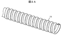
- FIG. 2A is a perspective view showing a structure of a metal tube used in the medical cable according to the embodiment of the present invention.
- 2B is a cross-sectional view showing an example of the metal tube expansion and contraction structure of FIG. 2A
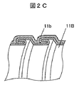
- FIG. 2C is a cross-sectional view showing an example different from FIG.
- the metal tube 11 has a bellows shape, and when the force is applied so that the convex portions adjacent to each other in the longitudinal direction approach each other, the tube contracts in the longitudinal direction and automatically releases if the force is released.
- the tube extends to its original length. Since the metal tube 11 does not bend more than a certain value and has a restoring force (straight advance) even if it is bent, the probe cable 10 as a whole is prevented from being bent more than a certain value, and the cable becomes strong. Thereby, the entanglement of the thinned cable and the buckling of the coaxial line can be suppressed.
- the expansion / contraction structure of the metal tube 11 is not particularly limited.
- a so-called Squarelock structure such as the metal tube 11A illustrated in FIG. 2B or the metal tube 11B illustrated in FIG. 2C is used.
- Such a so-called Interlock structure double lock structure is preferable. Interlock structure is more preferable in terms of smoothness and strength of appearance.
- the coating layer 11b which consists of resin, such as PVC, is provided as FIG. 2C shows.
- the metal tube 11 is preferably made of a copper alloy, stainless steel, or aluminum alloy. Plating treatment such as zinc plating or tin plating may be performed.
- the size of the metal tube 11 is preferably, for example, an inner diameter of 2 ⁇ 0.2 mm and an outer diameter of 4 ⁇ 0.4 mm.
- the coaxial line unit 13 preferably has a coating layer on the outer periphery of a plurality of bundled coaxial lines.
- the number of the coaxial line units 13 is six in FIG. 1, it is not particularly limited, and the probe cable is preferably 4 to 10, for example.
- the plurality of coaxial lines constituting the coaxial line unit 13 may be twisted together.
- the number of coaxial lines is not particularly limited, but is, for example, 16 to 32.
- the coaxial line constituting the coaxial line unit 13 has a center conductor and an insulating layer coated or wound around the outer periphery of the center conductor.
- An interposition, an external conductor, a jacket (sheath), and the like may be provided.
- the center conductor may be a single wire or a stranded wire.
- the center conductor is made of, for example, a copper alloy, and may be plated with silver plating or the like.
- As the center conductor is reduced in diameter for example, 42-50 AWG (American Wire Gauge) is preferably used.
- the insulating layer is formed by extruding a resin selected from, for example, fluororesin, polyethylene (PE), and polypropylene (PP).
- the thickness of the insulating layer is, for example, 8 to 30 ⁇ m.
- the metal braided shield 15 is preferably formed by weaving flat wire having a substantially rectangular cross section. In order to avoid damage to the binding tape 14 and the sheath 16, it is desirable to use a rounded strand, and a flat strand formed by rolling a strand having a circular cross section is used. desirable.
- the thickness of the flat wire is preferably about 0.1 to 0.15 mm, and the width of the flat wire is preferably about 0.5 to 2 mm.
- the sheath 16 is made of a medical insulating resin.
- a medical insulating resin is a biocompatible (highly biocompatible) resin that is non-toxic and does not cause allergies such as inflammation when it comes into contact with a living body. It is also called a grade resin.
- medical grade PVC polyvinyl chloride
- FIG. 3 is a cross-sectional view showing the structure of the medical cable according to the second embodiment of the present invention.
- the probe cable 20 as a medical cable according to the second embodiment of the present invention has a single bellows-like flexible metal tube 21 (second metal tube).
- the metal tube 21 is disposed outside the coaxial line unit 13. That is, the coaxial line unit 13 is disposed in the pipe of the metal pipe 21.
- the configuration of the probe cable 20 shown in FIG. 3 will be described in more detail.
- the probe cable 20 includes an intermediary 22 made of an aramid fiber or the like disposed at the center of the cross section of the cable, and a plurality of coaxial line units 13 (six in FIG. 3) disposed on the outer periphery of the probe cable 20 and bundling a plurality of coaxial lines.
- a sheath 16 made of PVC or the like. Since the configurations denoted by the same reference numerals as those in the first embodiment are the same as those in the first embodiment, description thereof will be omitted.
- the metal tube 21 may be provided with a resin coating layer 12 formed by fully extruding a resin such as PVC or winding a bind tape.
- the metal tube 21 is a bellows-like flexible metal tube having the same characteristics as the metal tube 11 in the first embodiment described above, but the size is larger than that of the metal tube 11 in the first embodiment.
- the size is larger than that of the metal tube 11 in the first embodiment.
- those having an inner diameter of 6 ⁇ 0.5 mm and an outer diameter of 8 ⁇ 0.5 mm are suitable.
- the metal braided shield 15 in the first embodiment is not provided. This is because the metal tube 21 also functions as a shield. Since there is no gap on the outer surface of the metal tube 21, the shielding performance is improved compared to the braid.
- a metal braided shield 15 may be provided, and in this case, it is preferable to provide it between the bind tape 14 and the metal tube 21.
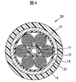
- FIG. 4 is a cross-sectional view showing the structure of the medical cable according to the third embodiment of the present invention.
- a probe cable 30 as a medical cable according to the third embodiment of the present invention is a fusion type of the first embodiment and the second embodiment described above, and relates to the first embodiment.
- the metal braided shield 15 in the probe cable 10 is replaced with the metal tube 21 in the probe cable 20 according to the second embodiment. That is, the probe cable 30 has two bellows-like flexible metal tubes 11 and 21 (first and second metal tubes).
- the first and second embodiments are superior, but the effect of the present invention that suppresses the entanglement of the reduced diameter cable and the buckling of the coaxial line is the same as that of the present embodiment. Is easier to demonstrate.
- Medical cables other than probe cables that is, catheter cables and endoscope cables, basically have the same structure as the probe cables except that the number of coaxial cables is different.
- a catheter cable may be configured with only one coaxial cable.
- a power supply line and other signal lines may be included.
- the medical device which concerns on embodiment of this invention has the said medical cable which concerns on embodiment of this invention, and the terminal component with which the edge part of the said medical cable was equipped.
- the medical device according to the embodiment of the present invention refers to a medical device body such as a measuring device, the medical cable used for wiring, and a terminal such as a probe provided at the end of the cable.
- a medical device body such as a measuring device, the medical cable used for wiring, and a terminal such as a probe provided at the end of the cable.
- the case of being composed of the medical cable and terminal parts such as a probe provided at the end of the cable is also included.
- An example of the latter is a harness.
- FIG. 5 is a schematic diagram showing a harness heat dissipation mechanism using the medical cable according to the embodiment of the present invention.
- the configuration of the harness 100 as a medical device according to the embodiment of the present invention will be described in detail below.
- the core wire 1 (the central conductor of the coaxial line) of the probe cable 10 according to the first embodiment is connected to a connection portion 52 on an internal substrate 51 of a terminal component 50 such as an ultrasonic probe.
- the internal substrate 51 is made of PCB (printed circuit board) or FPC (flexible printed circuit board), and the internal substrate 51 is mounted with an IC or the like as the heat generating portion 53.
- the braided shield 15 is caulked and fixed, and the caulking ring 41, the caulking ring 41, and / or the metal tube fixed to the housing 54 (only a part is shown) of the terminal component 50. 11 and a heat collecting metal pipe 42 that is thermally connected to the heat generating portion 53 and is connected to the heat generating portion 53.
- the heat generated in the heat generating portion 53 is transmitted to the braided shield 15 via the metal pipe 42 and the caulking ring 41, or is transmitted to the metal tube 11 via the metal pipe 42, Heat is dissipated outside the terminal component 50.
- the metal pipe 42 it is preferable to use a metal having high thermal conductivity, for example, copper or aluminum. Since the metal pipe 42 has a large surface area, the heat collecting effect is large, and the heat generated in the heat generating portion 53 can be efficiently collected and transmitted to the braided shield 15 and / or the metal pipe 11.
- the metal pipe 42 and the heat generating part 53 may be in direct contact or may not be in contact. Moreover, you may comprise so that the metal pipe 42 and the heat-emitting part 53 may contact via a heat radiating sheet etc. Although the case where two metal pipes 42 are used is shown here, the number of metal pipes 42 is not limited to this.
- the caulking ring 41 and the metal pipe 42 are thermally connected by caulking and fixing the cable 10 and the metal pipe 42 with the caulking ring 41.
- the ring 41 and the metal pipe 42 may be provided integrally, or the caulking ring 41 and the metal pipe 42 may be indirectly contacted and thermally connected via another member (for example, a housing). Also good.
- the metal pipe 42 and the metal pipe 11 are thermally connected by inserting and contacting the metal pipe 42 into the pipe of the metal pipe 11, but not limited thereto, the metal pipe 42 and the metal pipe 11 are connected. It may be integrated, or may be indirectly contacted and thermally connected via another member.
- This configuration makes it possible to efficiently dissipate heat outside the terminal component 50. For this reason, in this embodiment, it is possible to improve the heat dissipation efficiency without adding a member such as a cooling tube, and it is lighter and easier to bend than when a member such as a cooling tube is added.
- a highly efficient harness 100 can be realized. Further, in the present embodiment, a device for circulating the cooling liquid is not necessary, so that the cost is low.
Landscapes
- Life Sciences & Earth Sciences (AREA)
- Health & Medical Sciences (AREA)
- Biomedical Technology (AREA)
- Biophysics (AREA)
- Nuclear Medicine, Radiotherapy & Molecular Imaging (AREA)
- Pathology (AREA)
- Radiology & Medical Imaging (AREA)
- Engineering & Computer Science (AREA)
- Physics & Mathematics (AREA)
- Heart & Thoracic Surgery (AREA)
- Medical Informatics (AREA)
- Molecular Biology (AREA)
- Surgery (AREA)
- Animal Behavior & Ethology (AREA)
- General Health & Medical Sciences (AREA)
- Public Health (AREA)
- Veterinary Medicine (AREA)
- Ultra Sonic Daignosis Equipment (AREA)
Abstract
細径化してもケーブルが絡みにくく、かつ同軸線が座屈するほど屈曲しない医療用ケーブル及び当該医療用ケーブルを使用した医療用機器を提供する。 医療用ケーブルであるプローブケーブル10は、同軸線ユニット13と、同軸線ユニット13の長手方向に沿って配置された1本以上の蛇腹状の可撓性金属管11とを有する。
Description
本発明は、医療用ケーブル及び医療用機器に関する。
超音波診断装置等の医療機器の配線に使用される医療用ケーブルには、プローブケーブル、カテーテルケーブル、内視鏡ケーブル等がある。プローブケーブルとしては、例えば特許文献1記載のものがある。
特許文献1にも記載されているように、医療用ケーブルには、軟らかさ、すなわち可撓性に優れることが求められている。
一方、最近では、医療機器の小型化に伴って、その配線に使用される医療用ケーブルは細径化されてきている。
しかし、医療用ケーブルが細径化するとケーブルに腰が無くなるため、ケーブルをひとまとまりに置いておくとケーブルが絡まりやすくなるという問題が生じる。
また、ケーブルが屈曲した際に、ケーブル中の同軸線が座屈してしまう問題も生じる。
そこで、本発明の目的は、細径化してもケーブルが絡みにくく、かつ同軸線が座屈するほど屈曲しない医療用ケーブル及び当該医療用ケーブルを使用した医療用機器を提供することにある。
本発明は、上記目的を達成するために、下記の医療用ケーブル及び医療用機器を提供する。
[1]同軸線ユニットと、前記同軸線ユニットの長手方向に沿って配置された1本以上の蛇腹状の可撓性金属管とを有する医療用ケーブル。
[2]前記金属管のうちの第1の金属管は、前記プローブケーブルの横断面中心に配置されており、前記同軸線ユニットは、前記第1の金属管の外周に配置されている前記[1]に記載の医療用ケーブル。
[3]前記同軸線ユニットは、前記金属管のうちの第2の金属管の管内に配置されている前記[1]又は[2]に記載の医療用ケーブル。
[4]前記金属管は、銅合金、ステンレス、又はアルミ合金からなる前記[1]~[3]のいずれか1つに記載の医療用ケーブル。
[5]金属編組シールドを有しない前記[3]に記載の医療用ケーブル。
[6]前記医療用ケーブルは、プローブケーブルである前記[1]~[5]のいずれか1つに記載の医療用ケーブル。
[7]前記[1]~[6]のいずれか1つに記載の医療用ケーブルと、前記医療用ケーブルの端部に備えられた端末部品とを有する医療用機器。
[8]前記端末部品における発熱を前記金属管に伝熱する機構を備えた前記[7]に記載の医療用機器。
[2]前記金属管のうちの第1の金属管は、前記プローブケーブルの横断面中心に配置されており、前記同軸線ユニットは、前記第1の金属管の外周に配置されている前記[1]に記載の医療用ケーブル。
[3]前記同軸線ユニットは、前記金属管のうちの第2の金属管の管内に配置されている前記[1]又は[2]に記載の医療用ケーブル。
[4]前記金属管は、銅合金、ステンレス、又はアルミ合金からなる前記[1]~[3]のいずれか1つに記載の医療用ケーブル。
[5]金属編組シールドを有しない前記[3]に記載の医療用ケーブル。
[6]前記医療用ケーブルは、プローブケーブルである前記[1]~[5]のいずれか1つに記載の医療用ケーブル。
[7]前記[1]~[6]のいずれか1つに記載の医療用ケーブルと、前記医療用ケーブルの端部に備えられた端末部品とを有する医療用機器。
[8]前記端末部品における発熱を前記金属管に伝熱する機構を備えた前記[7]に記載の医療用機器。
本発明によれば、細径化してもケーブルが絡みにくく、かつ同軸線が座屈するほど屈曲しない医療用ケーブル及び当該医療用ケーブルを使用した医療用機器を提供することができる。
〔医療用ケーブル〕
本発明の実施の形態に係る医療用ケーブルは、同軸線ユニットと、前記同軸線ユニットの長手方向に沿って配置された1本以上の蛇腹状の可撓性金属管とを有する。同軸線ユニットは、1本であっても複数本であってもよい。
本発明の実施の形態に係る医療用ケーブルは、同軸線ユニットと、前記同軸線ユニットの長手方向に沿って配置された1本以上の蛇腹状の可撓性金属管とを有する。同軸線ユニットは、1本であっても複数本であってもよい。
(第1の実施の形態)
図1は、本発明の第1の実施の形態に係る医療用ケーブルの構造を示す横断面図である。
本発明の第1の実施の形態に係る医療用ケーブルとしてのプローブケーブル10は、1本の蛇腹状の可撓性金属管11(第1の金属管)を有している。金属管11は、プローブケーブル10の横断面中心に配置されており、同軸線ユニット13が金属管11の外周に配置されている。
図1は、本発明の第1の実施の形態に係る医療用ケーブルの構造を示す横断面図である。
本発明の第1の実施の形態に係る医療用ケーブルとしてのプローブケーブル10は、1本の蛇腹状の可撓性金属管11(第1の金属管)を有している。金属管11は、プローブケーブル10の横断面中心に配置されており、同軸線ユニット13が金属管11の外周に配置されている。
図1に示すプローブケーブル10の構成をより詳細に説明する。
プローブケーブル10は、外周に樹脂被覆層12が設けられた金属管11と、その外周に配置された、同軸線を複数本束ねた同軸線ユニット13複数本(図1では6本)と、これらを束ねるためにその外周に巻き付けられたポリテトラフルオロエチレン(PTFE)等からなるバインドテープ14と、その周囲に設けられた銀めっき銅線などの金属線を編組してなる金属編組シールド15と、その周囲に被覆されたPVC等からなるシース16とから構成されている。
プローブケーブル10は、外周に樹脂被覆層12が設けられた金属管11と、その外周に配置された、同軸線を複数本束ねた同軸線ユニット13複数本(図1では6本)と、これらを束ねるためにその外周に巻き付けられたポリテトラフルオロエチレン(PTFE)等からなるバインドテープ14と、その周囲に設けられた銀めっき銅線などの金属線を編組してなる金属編組シールド15と、その周囲に被覆されたPVC等からなるシース16とから構成されている。
金属管11は、そのままでもよいが、同軸線ユニット13の外被を傷付けないために樹脂被覆層12が設けられていることが好ましい。樹脂被覆層12は、金属管11の外周に充実押出(材質:ポリ塩化ビニル樹脂(PVC)やポリウレタン等)されていることが好ましい。また、充実押出に換えて、バインドテープ(材質:PVCやポリウレタン等)を巻き付けるようにしてもよい。
ここで、本発明の実施の形態における蛇腹状の可撓性金属管とは、長手方向に引っ張っても伸びない、長手方向に収縮させる力を加えると3~10%程度収縮するが力を解放すると元の長さに戻る、可撓性を有するが一定以上は曲がらない、及び復元力(直進性)がある金属管をいう。このような特性を有する金属管であれば、特に限定されることなく市販の製品を使用することができる。
図2Aは、本発明の実施の形態に係る医療用ケーブルに使用される金属管の構造を示す斜視図である。図2Bは、図2Aの金属管の伸縮構造の一例を示す断面図であり、図2Cは、図2Bとは別の一例を示す断面図である。
金属管11は、図2Aに示されるように蛇腹状であり、長手方向に隣接する凸部同士が近づくように力を加えることで長手方向に管が収縮し、力を解放すれば、自動的に元の長さに管が伸長する。金属管11は、一定以上は曲がらず、曲げても復元力(直進性)があるため、プローブケーブル10全体としても一定以上曲がることが阻止され、またケーブルの腰が強くなる。これにより、細径化されたケーブルの絡み及び同軸線の座屈を抑制することができる。
金属管11の伸縮構造は、特に限定されるものではないが、例えば、図2Bに示される金属管11Aのような、いわゆるSquarelock構造(シングルのロック構造)や、図2Cに示される金属管11Bのような、いわゆるInterlock構造(ダブルのロック構造)であることが好ましい。Interlock構造であることが外観の滑らかさや強度の点でより好ましい。また、図2Cに示されるようにPVC等の樹脂からなる被覆層11bが設けられていることが好ましい。
金属管11は、銅合金、ステンレス、又はアルミ合金からなることが好ましい。亜鉛めっきや錫めっき等のメッキ処理が施されていてもよい。また、金属管11のサイズは、例えば、内径2±0.2mm、外径4±0.4mmであるものが好適である。
同軸線ユニット13は、図1に示されるように、束ねた複数本の同軸線の外周に被覆層を有していることが好ましい。同軸線ユニット13の本数は、図1では6本としたが、特に限定されるものではなく、プローブケーブルとしては、例えば、4~10本であることが好ましい。
同軸線ユニット13を構成する複数の同軸線は撚り合せられていてもよい。同軸線の本数は、特に限定されるものではないが、例えば、16~32本である。
同軸線ユニット13を構成する同軸線は、中心導体と、中心導体の外周に被覆又は巻き付けられた絶縁層とを有する。介在、外部導体、ジャケット(シース)等が設けられていてもよい。
中心導体は、単線でも撚線でもよい。中心導体は、例えば銅合金からなり、銀めっき等のめっきが施されていてもよい。中心導体はケーブルの細径化に伴い、例えば42~50AWG(American Wire Gauge)のものが好適に使用される。
絶縁層は、例えば、フッ素樹脂、ポリエチレン(PE)、ポリプロピレン(PP)から選ばれる樹脂を押出成形することにより形成されたものである。絶縁層の厚みは、例えば8~30μmである。
金属編組シールド15は、断面略矩形状の平角素線を編み込んで形成されることが好ましい。平角素線としては、バインドテープ14やシース16の損傷を避けるために、角を丸めたものを用いることが望ましく、断面円形状の素線を圧延加工して形成した平角素線を用いることが望ましい。平角素線の厚さは、0.1~0.15mm程度とするとよく、また、平角素線の幅は、0.5~2mm程度とするとよい。
シース16は、医療用絶縁樹脂からなる。医療用絶縁樹脂とは、毒性がなく生体と接触した際に炎症等のアレルギー症状を発生させることがない、生体適合性を有する(バイオコンパチビリティーが高い)樹脂であり、医療用樹脂、医療グレードの樹脂とも呼ばれるものである。例えば、医療用グレードのPVC(ポリ塩化ビニル)が好ましいものとして挙げられる。
(第2の実施の形態)
図3は、本発明の第2の実施の形態に係る医療用ケーブルの構造を示す横断面図である。
本発明の第2の実施の形態に係る医療用ケーブルとしてのプローブケーブル20は、1本の蛇腹状の可撓性金属管21(第2の金属管)を有している。金属管21は、同軸線ユニット13よりも外側に配置されている。すなわち、同軸線ユニット13は、金属管21の管内に配置されている。
図3は、本発明の第2の実施の形態に係る医療用ケーブルの構造を示す横断面図である。
本発明の第2の実施の形態に係る医療用ケーブルとしてのプローブケーブル20は、1本の蛇腹状の可撓性金属管21(第2の金属管)を有している。金属管21は、同軸線ユニット13よりも外側に配置されている。すなわち、同軸線ユニット13は、金属管21の管内に配置されている。
図3に示すプローブケーブル20の構成をより詳細に説明する。
プローブケーブル20は、ケーブルの横断面中心に配置されたアラミド繊維等からなる介在22と、その外周に配置された、同軸線を複数本束ねた同軸線ユニット13複数本(図3では6本)と、これらを束ねるためにその外周に巻き付けられたポリテトラフルオロエチレン(PTFE)等からなるバインドテープ14と、これらをその管内に収容するように設けられた金属管21と、その周囲に被覆されたPVC等からなるシース16とから構成されている。第1の実施の形態と同じ符号を付した構成については第1の実施の形態と同様であるので説明を省略する。
プローブケーブル20は、ケーブルの横断面中心に配置されたアラミド繊維等からなる介在22と、その外周に配置された、同軸線を複数本束ねた同軸線ユニット13複数本(図3では6本)と、これらを束ねるためにその外周に巻き付けられたポリテトラフルオロエチレン(PTFE)等からなるバインドテープ14と、これらをその管内に収容するように設けられた金属管21と、その周囲に被覆されたPVC等からなるシース16とから構成されている。第1の実施の形態と同じ符号を付した構成については第1の実施の形態と同様であるので説明を省略する。
金属管21は、前述の第1の実施の形態における金属管11の場合と同様に、PVC等の樹脂の充実押出又はバインドテープを巻き付けてなる樹脂被覆層12が設けられていてもよい。
金属管21は、前述の第1の実施の形態における金属管11と同様の特徴を有する蛇腹状の可撓性金属管であるが、サイズは第1の実施の形態における金属管11よりも大きく、例えば、同軸ケーブル128芯のプローブケーブルの場合、内径6±0.5mm、外径8±0.5mmであるものが好適である。
本実施の形態においては、前述の第1の実施の形態における金属編組シールド15を設けていない。これは、金属管21がシールドとしての機能も果たしているためである。金属管21には外表面に隙間が無いため、編組に比べシールド性能がアップする。なお、金属編組シールド15を設けてもよく、この場合、バインドテープ14と金属管21の間に設けることが好ましい。
(第3の実施の形態)
図4は、本発明の第3の実施の形態に係る医療用ケーブルの構造を示す横断面図である。
本発明の第3の実施の形態に係る医療用ケーブルとしてのプローブケーブル30は、前述の第1の実施の形態と第2の実施の形態の融合タイプであり、第1の実施の形態に係るプローブケーブル10における金属編組シールド15を第2の実施の形態に係るプローブケーブル20における金属管21に置換したものである。すなわち、プローブケーブル30は、2本の蛇腹状の可撓性金属管11、21(第1及び第2の金属管)を有している。
図4は、本発明の第3の実施の形態に係る医療用ケーブルの構造を示す横断面図である。
本発明の第3の実施の形態に係る医療用ケーブルとしてのプローブケーブル30は、前述の第1の実施の形態と第2の実施の形態の融合タイプであり、第1の実施の形態に係るプローブケーブル10における金属編組シールド15を第2の実施の形態に係るプローブケーブル20における金属管21に置換したものである。すなわち、プローブケーブル30は、2本の蛇腹状の可撓性金属管11、21(第1及び第2の金属管)を有している。
細径化の観点では、第1及び第2の実施の形態の方が勝るが、細径化したケーブルの絡み及び同軸線の座屈を抑制するという本発明の効果は本実施の形態の方がより発揮しやすい。
(その他の医療用ケーブル)
プローブケーブル以外の医療用ケーブル、すなわち、カテーテルケーブル、内視鏡ケーブルについても、同軸ケーブルの本数が異なる点を除けば基本的にプローブケーブル同様の構造を有している。なお、カテーテルケーブルにおいては、同軸ケーブルが1本のみで構成される場合がある。また、電源線やその他の信号線が含まれる場合がある。
プローブケーブル以外の医療用ケーブル、すなわち、カテーテルケーブル、内視鏡ケーブルについても、同軸ケーブルの本数が異なる点を除けば基本的にプローブケーブル同様の構造を有している。なお、カテーテルケーブルにおいては、同軸ケーブルが1本のみで構成される場合がある。また、電源線やその他の信号線が含まれる場合がある。
〔医療用機器〕
本発明の実施の形態に係る医療用機器は、本発明の実施の形態に係る上記医療用ケーブルと、前記医療用ケーブルの端部に備えられた端末部品とを有する。本実施の形態においては、前記端末部品における発熱を前記金属管に伝熱する機構が備えられていることが望ましい。
本発明の実施の形態に係る医療用機器は、本発明の実施の形態に係る上記医療用ケーブルと、前記医療用ケーブルの端部に備えられた端末部品とを有する。本実施の形態においては、前記端末部品における発熱を前記金属管に伝熱する機構が備えられていることが望ましい。
なお、本発明の実施の形態に係る医療用機器とは、測定装置等の医療機器本体と、配線に使用される上記医療用ケーブルと、ケーブルの端部に設けられた探触子等の端末部品とから構成される場合のほか、上記医療用ケーブルと、ケーブルの端部に設けられた探触子等の端末部品とから構成される場合も含む。後者の例としてハーネスが挙げられる。
図5は、本発明の実施の形態に係る医療用ケーブルを使用したハーネスの放熱機構を示す概略図である。
本発明の実施の形態に係る医療用機器としてのハーネス100の構成について、以下に詳細に説明する。
第1の実施の形態に係るプローブケーブル10の心線1(同軸線の中心導体)は、超音波探触子等の端末部品50の内部基板51上の接続部52に接続されている。内部基板51は、PCB(プリント基板)又はFPC(フレキシブルプリント基板)からなり、内部基板51には、発熱部53であるIC等が搭載されている。
本実施形態に係るハーネス100は、編組シールド15を加締め固定すると共に、端末部品50のハウジング54(一部のみ図示)に固定される加締めリング41と、加締めリング41及び/又は金属管11と熱的に接続され発熱部53の近傍まで延出される集熱用の金属パイプ42と、を備えている。
このように構成することで、発熱部53で発生した熱は、金属パイプ42、加締めリング41を介して編組シールド15に伝達され、あるいは、金属パイプ42を介して金属管11に伝達され、端末部品50の外部に散熱される。
金属パイプ42としては、熱伝導率が高い金属、例えば銅やアルミニウムからなるものを用いるとよい。金属パイプ42は、表面積が大きいため集熱効果が大きく、発熱部53で発生した熱を効率よく集熱して編組シールド15及び/又は金属管11に伝達することが可能である。金属パイプ42と発熱部53とは直接接触していてもよいし、接触していなくともよい。また、放熱シート等を介して金属パイプ42と発熱部53とが接触するように構成してもよい。ここでは、金属パイプ42を2本用いる場合を示しているが、金属パイプ42の数はこれに限定されるものではない。
また、ここでは、ケーブル10と金属パイプ42を加締めリング41で加締め固定することで、加締めリング41と金属パイプ42とを熱的に接続したが、これに限らず、例えば、加締めリング41と金属パイプ42を一体に設けるようにしてもよいし、加締めリング41と金属パイプ42とを他の部材(例えばハウジング)を介して間接的に接触させ熱的に接続するようにしてもよい。また、金属パイプ42を金属管11の管内に挿入して接触させることで、金属パイプ42と金属管11とを熱的に接続したが、これに限らず、金属パイプ42と金属管11とを一体としてもよいし、他の部材を介して間接的に接触させ熱的に接続するようにしてもよい。
このように構成することで、端末部品50の外部に熱を効率よく散熱することが可能になる。このため、本実施形態では、冷却チューブ等の部材を追加することなく散熱効率を向上させることが可能であり、冷却チューブ等の部材を追加した場合と比較して、軽量でかつ屈曲し易く操作性の高いハーネス100を実現できる。また、本実施形態では冷却液体を循環させる装置等が必要ないため、低コストである。
なお、本発明は、上記実施の形態に限定されず種々に変形実施が可能である。
10,20,30:プローブケーブル
11,11A,11B:金属管、12:樹脂被覆層
13:同軸線ユニット、14:バインドテープ
15:編組シールド、16:シース
21:金属管、22:介在
41:加締めリング、42:金属パイプ
50:端末部品、51:内部基板、52:接続部
53:発熱部、54:ハウジングの一部
100:ハーネス
11,11A,11B:金属管、12:樹脂被覆層
13:同軸線ユニット、14:バインドテープ
15:編組シールド、16:シース
21:金属管、22:介在
41:加締めリング、42:金属パイプ
50:端末部品、51:内部基板、52:接続部
53:発熱部、54:ハウジングの一部
100:ハーネス
Claims (8)
- 同軸線ユニットと、前記同軸線ユニットの長手方向に沿って配置された1本以上の蛇腹状の可撓性金属管とを有する医療用ケーブル。
- 前記金属管のうちの第1の金属管は、前記プローブケーブルの横断面中心に配置されており、前記同軸線ユニットは、前記第1の金属管の外周に配置されている請求項1に記載の医療用ケーブル。
- 前記同軸線ユニットは、前記金属管のうちの第2の金属管の管内に配置されている請求項1又は請求項2に記載の医療用ケーブル。
- 前記金属管は、銅合金、ステンレス、又はアルミ合金からなる請求項1~3のいずれか1項に記載の医療用ケーブル。
- 金属編組シールドを有しない請求項3に記載の医療用ケーブル。
- 前記医療用ケーブルは、プローブケーブルである請求項1~5のいずれか1項に記載の医療用ケーブル。
- 請求項1~6のいずれか1項に記載の医療用ケーブルと、前記医療用ケーブルの端部に備えられた端末部品とを有する医療用機器。
- 前記端末部品における発熱を前記金属管に伝熱する機構を備えた請求項7に記載の医療用機器。
Priority Applications (1)
| Application Number | Priority Date | Filing Date | Title |
|---|---|---|---|
| PCT/JP2015/071333 WO2017017778A1 (ja) | 2015-07-28 | 2015-07-28 | 医療用ケーブル及び医療用機器 |
Applications Claiming Priority (1)
| Application Number | Priority Date | Filing Date | Title |
|---|---|---|---|
| PCT/JP2015/071333 WO2017017778A1 (ja) | 2015-07-28 | 2015-07-28 | 医療用ケーブル及び医療用機器 |
Publications (1)
| Publication Number | Publication Date |
|---|---|
| WO2017017778A1 true WO2017017778A1 (ja) | 2017-02-02 |
Family
ID=57885464
Family Applications (1)
| Application Number | Title | Priority Date | Filing Date |
|---|---|---|---|
| PCT/JP2015/071333 Ceased WO2017017778A1 (ja) | 2015-07-28 | 2015-07-28 | 医療用ケーブル及び医療用機器 |
Country Status (1)
| Country | Link |
|---|---|
| WO (1) | WO2017017778A1 (ja) |
Cited By (2)
| Publication number | Priority date | Publication date | Assignee | Title |
|---|---|---|---|---|
| JP2022124502A (ja) * | 2021-02-16 | 2022-08-26 | 富士フイルム株式会社 | 超音波内視鏡 |
| US20240055153A1 (en) * | 2022-08-12 | 2024-02-15 | Proterial, Ltd. | Multicore cable and multicore cable assembly |
Citations (3)
| Publication number | Priority date | Publication date | Assignee | Title |
|---|---|---|---|---|
| JP2005276477A (ja) * | 2004-03-23 | 2005-10-06 | Shinagawa Shoko Kk | 電気機器接続用ケーブル |
| WO2014006954A1 (ja) * | 2012-07-04 | 2014-01-09 | オリンパスメディカルシステムズ株式会社 | 超音波内視鏡 |
| JP2015504584A (ja) * | 2011-11-28 | 2015-02-12 | コーニンクレッカ フィリップス エヌ ヴェ | 医療装置用ケーブル |
-
2015
- 2015-07-28 WO PCT/JP2015/071333 patent/WO2017017778A1/ja not_active Ceased
Patent Citations (3)
| Publication number | Priority date | Publication date | Assignee | Title |
|---|---|---|---|---|
| JP2005276477A (ja) * | 2004-03-23 | 2005-10-06 | Shinagawa Shoko Kk | 電気機器接続用ケーブル |
| JP2015504584A (ja) * | 2011-11-28 | 2015-02-12 | コーニンクレッカ フィリップス エヌ ヴェ | 医療装置用ケーブル |
| WO2014006954A1 (ja) * | 2012-07-04 | 2014-01-09 | オリンパスメディカルシステムズ株式会社 | 超音波内視鏡 |
Cited By (7)
| Publication number | Priority date | Publication date | Assignee | Title |
|---|---|---|---|---|
| JP2022124502A (ja) * | 2021-02-16 | 2022-08-26 | 富士フイルム株式会社 | 超音波内視鏡 |
| CN114938975A (zh) * | 2021-02-16 | 2022-08-26 | 富士胶片株式会社 | 超声波内窥镜 |
| JP7628831B2 (ja) | 2021-02-16 | 2025-02-12 | 富士フイルム株式会社 | 超音波内視鏡 |
| US20240055153A1 (en) * | 2022-08-12 | 2024-02-15 | Proterial, Ltd. | Multicore cable and multicore cable assembly |
| JP2024025296A (ja) * | 2022-08-12 | 2024-02-26 | 株式会社プロテリアル | 多芯ケーブル及び多芯ケーブルアッセンブリ |
| JP7468582B2 (ja) | 2022-08-12 | 2024-04-16 | 株式会社プロテリアル | 多芯ケーブル及び多芯ケーブルアッセンブリ |
| JP7670195B2 (ja) | 2022-08-12 | 2025-04-30 | 株式会社プロテリアル | 多芯ケーブルアッセンブリ |
Similar Documents
| Publication | Publication Date | Title |
|---|---|---|
| KR101614579B1 (ko) | 다심 케이블 | |
| JP2723894B2 (ja) | 可撓性遮蔽ケーブル | |
| JP2015185323A (ja) | プローブケーブル及びそれを用いたハーネス | |
| JP2011187323A (ja) | 極細シールドケーブル及びこれを用いたハーネス | |
| JP6471909B2 (ja) | ワイヤハーネス | |
| US20190074110A1 (en) | Multicore cable | |
| US12230418B2 (en) | Composite cable | |
| US20150279515A1 (en) | Cable and harness using the cable | |
| JP6551733B2 (ja) | 多芯シールドケーブル及びその分岐方法 | |
| WO2017017778A1 (ja) | 医療用ケーブル及び医療用機器 | |
| JP2015118840A (ja) | 遮水テープ、遮水ケーブル | |
| JP6841257B2 (ja) | ワイヤハーネス | |
| CN203931563U (zh) | 多芯线缆 | |
| JP7452098B2 (ja) | ケーブル | |
| JP2023141013A (ja) | シールド付き対撚り電線 | |
| US20190092255A1 (en) | Wire harness | |
| JP6065756B2 (ja) | ケーブルの接続構造 | |
| JP6217601B2 (ja) | ワイヤーハーネス | |
| US20150340129A1 (en) | Harness | |
| CN110323635A (zh) | 形状保持的电缆组件 | |
| US20170108658A1 (en) | Multiple circuit cable | |
| JP6713712B2 (ja) | 多芯ケーブル | |
| EP3975205B1 (en) | Shielded wire and wire harness | |
| JP5516499B2 (ja) | 細径ケーブル | |
| JPS6063515A (ja) | 内視鏡用可撓管 |
Legal Events
| Date | Code | Title | Description |
|---|---|---|---|
| 121 | Ep: the epo has been informed by wipo that ep was designated in this application |
Ref document number: 15899611 Country of ref document: EP Kind code of ref document: A1 |
|
| NENP | Non-entry into the national phase |
Ref country code: DE |
|
| NENP | Non-entry into the national phase |
Ref country code: JP |
|
| 122 | Ep: pct application non-entry in european phase |
Ref document number: 15899611 Country of ref document: EP Kind code of ref document: A1 |