WO2017013898A1 - 電解セルおよびこの電解セルを備える電解水生成装置 - Google Patents
電解セルおよびこの電解セルを備える電解水生成装置 Download PDFInfo
- Publication number
- WO2017013898A1 WO2017013898A1 PCT/JP2016/058351 JP2016058351W WO2017013898A1 WO 2017013898 A1 WO2017013898 A1 WO 2017013898A1 JP 2016058351 W JP2016058351 W JP 2016058351W WO 2017013898 A1 WO2017013898 A1 WO 2017013898A1
- Authority
- WO
- WIPO (PCT)
- Prior art keywords
- chamber
- electrolytic
- water
- anode
- electrolytic cell
- Prior art date
- Legal status (The legal status is an assumption and is not a legal conclusion. Google has not performed a legal analysis and makes no representation as to the accuracy of the status listed.)
- Ceased
Links
Images



Classifications
-
- C—CHEMISTRY; METALLURGY
- C25—ELECTROLYTIC OR ELECTROPHORETIC PROCESSES; APPARATUS THEREFOR
- C25B—ELECTROLYTIC OR ELECTROPHORETIC PROCESSES FOR THE PRODUCTION OF COMPOUNDS OR NON-METALS; APPARATUS THEREFOR
- C25B9/00—Cells or assemblies of cells; Constructional parts of cells; Assemblies of constructional parts, e.g. electrode-diaphragm assemblies; Process-related cell features
-
- C—CHEMISTRY; METALLURGY
- C02—TREATMENT OF WATER, WASTE WATER, SEWAGE, OR SLUDGE
- C02F—TREATMENT OF WATER, WASTE WATER, SEWAGE, OR SLUDGE
- C02F1/00—Treatment of water, waste water, or sewage
- C02F1/28—Treatment of water, waste water, or sewage by sorption
-
- C—CHEMISTRY; METALLURGY
- C02—TREATMENT OF WATER, WASTE WATER, SEWAGE, OR SLUDGE
- C02F—TREATMENT OF WATER, WASTE WATER, SEWAGE, OR SLUDGE
- C02F1/00—Treatment of water, waste water, or sewage
- C02F1/42—Treatment of water, waste water, or sewage by ion-exchange
-
- C—CHEMISTRY; METALLURGY
- C02—TREATMENT OF WATER, WASTE WATER, SEWAGE, OR SLUDGE
- C02F—TREATMENT OF WATER, WASTE WATER, SEWAGE, OR SLUDGE
- C02F1/00—Treatment of water, waste water, or sewage
- C02F1/46—Treatment of water, waste water, or sewage by electrochemical methods
-
- C—CHEMISTRY; METALLURGY
- C25—ELECTROLYTIC OR ELECTROPHORETIC PROCESSES; APPARATUS THEREFOR
- C25B—ELECTROLYTIC OR ELECTROPHORETIC PROCESSES FOR THE PRODUCTION OF COMPOUNDS OR NON-METALS; APPARATUS THEREFOR
- C25B15/00—Operating or servicing cells
- C25B15/08—Supplying or removing reactants or electrolytes; Regeneration of electrolytes
-
- C—CHEMISTRY; METALLURGY
- C25—ELECTROLYTIC OR ELECTROPHORETIC PROCESSES; APPARATUS THEREFOR
- C25B—ELECTROLYTIC OR ELECTROPHORETIC PROCESSES FOR THE PRODUCTION OF COMPOUNDS OR NON-METALS; APPARATUS THEREFOR
- C25B9/00—Cells or assemblies of cells; Constructional parts of cells; Assemblies of constructional parts, e.g. electrode-diaphragm assemblies; Process-related cell features
- C25B9/60—Constructional parts of cells
-
- C—CHEMISTRY; METALLURGY
- C25—ELECTROLYTIC OR ELECTROPHORETIC PROCESSES; APPARATUS THEREFOR
- C25B—ELECTROLYTIC OR ELECTROPHORETIC PROCESSES FOR THE PRODUCTION OF COMPOUNDS OR NON-METALS; APPARATUS THEREFOR
- C25B11/00—Electrodes; Manufacture thereof not otherwise provided for
- C25B11/02—Electrodes; Manufacture thereof not otherwise provided for characterised by shape or form
- C25B11/03—Electrodes; Manufacture thereof not otherwise provided for characterised by shape or form perforated or foraminous
Definitions
- the problem to be solved by the present embodiment is to provide an electrolysis cell that is easy to assemble and has small water supply and drainage pressure loss, and an electrolyzed water generating apparatus including the electrolysis cell.
- the electrolytic cell includes a main body member in which an electrolytic solution chamber is formed, and a cover member that is assembled to the main body member along the stacking direction to form at least one generation chamber; A diaphragm that partitions the electrolytic solution chamber and the generated water chamber, and a pair of electrodes that face each other across the electrolytic solution chamber, wherein at least one electrode is provided in the generated water chamber, and the diaphragm and the generated water chamber And a pair of electrodes provided side by side in the stacking direction, and the outer contour of the cross section of the electrolytic vessel has a protruding portion that protrudes outward along the stacking direction.
- Sodium ions ionized in the salt water flowing into the electrolyte chamber 15a are attracted to the cathode 20, pass through the cation exchange membrane 18, and flow into the cathode chamber 15c.
- water is decomposed at the cathode 20 to generate hydrogen gas, and an aqueous sodium hydroxide solution is obtained.
- the sodium hydroxide aqueous solution and hydrogen gas generated in this way flow out from the cathode chamber 15c to the second drain pipe 21c, and are separated into the sodium hydroxide aqueous solution and hydrogen gas by the gas-liquid separator 27.
- the separated sodium hydroxide aqueous solution (alkaline water) is discharged through the second drain pipe 21c.
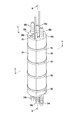
- FIG. 2 is a perspective view of the electrolytic cell
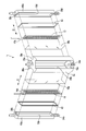
- FIG. 3 is an exploded perspective view of the electrolytic cell
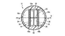
- FIG. 4 is a cross-sectional view of the electrolytic cell along line AA in FIG. 2
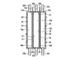
- FIG. 5 is a line BB in FIG. It is a longitudinal cross-sectional view of the electrolytic cell in alignment with.
- the electrolytic cell 11 has an intermediate frame 22 as a main body member, an anode cover 24 as a cover member, and a cathode cover 26 as a second cover member, which are fitted to each other. By doing so, an overall cylindrical appearance with both axial ends closed as a whole is formed.
- the intermediate frame 22 is formed in an elongated rectangular frame shape.
- the intermediate frame 22 forms an electrolyte chamber 15a by its inner peripheral surface.
- the reinforcing plate 13 is provided inside the intermediate frame 22 and extends coaxially with the intermediate frame 22.
- a first inlet socket 34a that communicates with the electrolyte chamber 15a protrudes from the lower end in the axial direction of the intermediate frame 22, and a first outlet socket 36a that communicates with the electrolyte chamber 15a at the upper end in the axial direction. Projected.
- the first inlet socket 34a and the first outlet socket 36a are each formed by an elongated sleeve extending in parallel with the axial direction of the electrolytic cell 11, and constitute a pipe connecting portion for connecting pipes.
- the second inlet socket 34b and the second outlet socket 36b are each formed of an elongated sleeve extending in parallel with the axial direction of the electrolytic cell 11, and constitute a pipe connection part for connecting pipes.
- a notch 25 is formed in the lower end wall 24d.
- the cathode cover 26 is formed in an elongated dish shape, and has an arc-shaped peripheral wall 26a, a pair of opposing side walls 26b, an upper end wall 26c, and a lower end wall 26d. The distance between the pair of side walls corresponds to the width of the recess 24 b of the anode cover 24.
- the cathode cover 26 forms a cathode chamber 15c by its inner surface.
- a third inlet socket 34c that communicates with the cathode chamber 15c is formed on the lower end wall 26d, and a third outlet socket 36c that communicates with the cathode chamber 15c is provided on the upper end wall 26c.
- the 3rd inflow socket 34c and the 3rd outflow socket 36c comprise the piping connection part extended in parallel with the axial direction of the electrolytic cell 11, respectively.
- the anode 14 is formed of a metal flat plate having a thickness of about 1 mm, and is formed in a rectangular shape having an outer diameter substantially the same as the outer diameter of the intermediate frame 22. A fine through hole for allowing liquid to pass through is formed in the central portion (effective region) of the anode 14.
- the anode 14 has a connection terminal 14b protruding from one end, for example, the upper end. The connection terminal 14b is connected to the power supply 45.
- the intermediate frame 22 is fitted in the recess 24 b of the anode cover 24 and is positioned in parallel with the anode cover 24.
- One opening of the intermediate frame 22 faces the anode chamber 15b in parallel.
- both side walls and the lower end wall of the intermediate frame 22 are covered with an anode cover 24.
- the upper end wall of the intermediate frame 22 is located in the same plane as the upper end wall 24 c of the anode cover 24.
- the first inlet socket 34 a of the intermediate frame 22 protrudes downward through the notch 25 of the anode cover 24.
- a cation exchange membrane 18 is disposed between the intermediate frame 22 and the cathode cover 26, and separates the electrolyte chamber 15a and the cathode chamber 15c.
- the cathode 20 is disposed between the cation exchange membrane 18 and the cathode cover 26, faces the cathode chamber 15c, and is in close proximity to the cation exchange membrane 18.
- a rectangular frame-shaped sealing material 40 b is disposed between the peripheral edge of the cathode 20 and the cathode cover 26.
- the fastening member for example, a plurality of elastic rubber bands 50 wound around or attached to the outer periphery of the electrolytic cell 11 are provided over the entire circumference.
- the rubber band 50 is attached at an appropriate interval in the axial direction of the electrolytic cell 11.
- the peripheral portions of the constituent members of the electrolytic cell 11 are pressed against each other, and the water tightness of the electrolyte chamber 15a, the anode chamber 15b, the first cathode chamber 30a, and the second cathode chamber 30b is improved. keeping.
- the sealing materials 40a and 40b are compressed by the contraction force of the rubber band 50 and seal each member in a liquid-tight manner.
- the first, second and third inlet sockets 34 a, 34 b and 34 c extend downward from the lower end of the electrolytic cell 11 along a direction parallel to the central axis of the electrolytic cell 11.
- the first, second, and third outlet sockets 36 a, 36 b, and 36 c extend upward from the upper end of the electrolytic cell 11 along a direction parallel to the central axis of the electrolytic cell 11.
- the sockets arranged at both ends in the axial direction of the cylindrical electrolytic cell 11 are arranged inside the cylindrical cross section so as not to obstruct the assembly of the fastening member.
- the anode cover 24, the anode 14, the anion exchange membrane 16, the intermediate frame 22, the cation exchange membrane 18, the cathode 20, and the cathode cover 26 are orthogonal to the anode 14 and the cathode 20, for example, orthogonal to each other. They are stacked or overlaid in the D direction, here the radial direction of the cylinder (diameter direction). That is, the anode 14, the anion exchange membrane 16, the intermediate frame 22, the cation exchange membrane 18, the cathode 20, and the cathode cover 26 are assembled to the anode cover so as to be displaceable in the D direction.
- the anode cover 24 and the cathode cover 26 are curved to protrude in the stacking direction D with respect to the electrodes 14, 20 and the ion exchange membranes 16, 18, or have an outer contour shape having protruding protrusions. Is formed.
- the electrolytic cell 11 is formed in a cylindrical shape, and the outer peripheral surface of the anode cover 24 and the outer peripheral surface of the cathode cover 26 are arc-shaped protrusions that are convex in the stacking direction D with respect to the electrode and the ion exchange membrane. Is forming. Therefore, each constituent element can be pressed in the stacking direction D by the fastening member such as the rubber band 50 attached to the outer periphery of the electrolytic cell 11 and can be easily and reliably fastened.
- each chamber of the electrolytic cell 11 has a structure extending in the axial direction (longitudinal direction) of the cylinder, and water supply and drainage are performed. Are installed in parallel to this axial direction. Therefore, it is easy to ensure a cross section of flowing water when flowing water, and since there is no bending, the pressure loss of flowing water can be extremely reduced. For this reason, it is possible to increase the flow rate that can flow into the electrolytic cell 11 even with a small supply water pressure.
- the electrolytic cell 11 has a cylindrical shape or a cylindrical shape, and can be obtained even when the cross section is an ellipse or a rounded rectangle. That is, what is necessary is just the swelling cross-sectional shape which can be fastened by narrowing the cross section itself of an electrolytic cell with respect to the structure which laminates
- Various shapes can be applied as long as the shape has an outer contour that is convex in the stacking direction of the constituent members.
- the electrolytic solution is salt water and the generated water is hypochlorous acid water, but the present invention is not limited to these, and various electrolytic solutions and generated water can be applied.
- a two-diaphragm three-chamber type electrolytic cell is used, but the electrolytic cell is not limited to this, and a single-diaphragm two-chamber type configuration may be used.
- the electrolytic cell may have three or more generated water chambers.
- FIG. 6 is a diagram schematically showing a configuration of the entire electrolyzed water generating apparatus according to the second embodiment.
- the electrolytic cell (electrolysis cell, electrolytic vessel) 11 of the electrolyzed water generating apparatus includes a third generated water chamber in addition to the first generated water chamber and the second generated water chamber.
- the electrolytic cell 11 is formed in a substantially cylindrical shape, and the inside of the electrolytic cell 11 is constituted by two anion exchange membranes (first diaphragms) 16a and 16b and a cation exchange membrane (second diaphragm) 18 which will be described later.
- the electrolyzed water generating apparatus supplies an electrolytic solution water, for example, water, to the electrolytic solution supply unit 19 for supplying an electrolytic solution, for example, saturated saline, to the electrolytic solution chamber 15a of the electrolytic cell 11, and the cathode chamber 15c and the second anode chamber 15d.
- the water supply part 21 to supply is provided, and the current supply part 23 which has the power supply 45 and applies a positive voltage and a negative voltage to the 1st, 2nd anodes 14 and 17 and the cathode 20 is provided.
- These recesses 58a, 58b, and 58c are provided at equal intervals in the circumferential direction of the intermediate frame 22. Each recess extends over the entire axial length of the intermediate frame 22 and has a depth in the radial direction from the outer periphery of the intermediate frame 22 toward the center.
- the outer peripheral surfaces of the first, second, and third covers 60a, 60b, and 60c are continuous with the outer peripheral surface of the intermediate frame 22 and constitute a part of a cylindrical shape.
- the 1st, 2nd, 3rd cover 60a, 60b, 60c forms the curved protrusion (outer peripheral surface) which becomes convex in the lamination direction D with respect to the electrode and diaphragm which are mentioned later.
- the first cover 60a forms an anode chamber 15b by a recess formed on the inner surface thereof
- the second cover 60b forms a cathode chamber 15c by a recess formed on the inner surface thereof
- the third cover 60c is formed on the inner surface thereof.
- a second anode chamber 15d is formed by the formed recess.
- the anode chamber 15b, the cathode chamber 15c, and the second anode chamber 15d extend in parallel with the axial direction in the electrolytic cell 11, respectively.
- an anion exchange membrane 16a is disposed as a first diaphragm, and separates the electrolyte chamber 15a and the anode chamber 15b.
- the first anode 14 is provided in the anode chamber 15 b and is close to and faces the anion exchange membrane 16.
- a sealing material 40 for preventing water leakage is disposed between the peripheral edge portion of the first anode 14 and the first cover 60a.
- the sealing material 40 has a rectangular frame shape having an outer diameter substantially equal to the outer diameter of the electrode, and is formed of, for example, a rubber material rich in elasticity having a thickness of about 1 mm.
- the first cover 60 a, the sealing material 40, the first anode 14, and the anion exchange membrane 16 a are stacked in the stacking direction D (the radial direction of the intermediate frame 22) D orthogonal to the first anode 14.
- the anion exchange membranes 16a and 16b and the cation exchange membrane 18 have the same shape, for example, an elongated rectangular shape, and have a film thickness of about 100 to 200 ⁇ m.
- the anion exchange membranes 16a and 16b and the cation exchange membrane 18 have a characteristic of allowing only specific ions to pass therethrough.
- the anion exchange membranes 16 a and 16 b and the cation exchange membrane 18 are arranged to face one surface of the intermediate frame 22, and the peripheral edge thereof is in close contact with the intermediate frame 22.
- the first diaphragm and the second diaphragm are not limited to ion exchange membranes, and may be porous membranes having water permeability.
- connection terminal 14b of the first anode 14 and the connection terminal 17b of the second anode 17 are connected to the positive side of the power supply 45, respectively.
- connection terminal 20 b of the cathode 20 is connected to the negative side of the power supply 45.
- a plurality of rubber bands 50 rich in elasticity are attached to the outer periphery of the electrolytic cell 11 as tightening members.
- the rubber band 50 is attached at an appropriate interval in the axial direction of the electrolytic cell 11.
- the peripheral portions of the constituent members of the electrolytic cell 11 are pressed against each other, and the water tightness of the electrolyte chamber 15a, the anode chamber 15b, the cathode chamber 15c, and the second anode chamber 15d is maintained. is doing.
- the sealing material 40 is compressed by the contraction force of the rubber band 50, and seals between the members in a liquid-tight manner.
- the supply pipe 19a, the connection pipe 54, and the water supply pipe 21a are connected to the first, second, third, and fourth inlet sockets 34a, 34b, 34c, and 34d, respectively.
- the circulation pipe 19b, the first drain pipe 21b, the second drain pipe 21c, and the connection pipe 54 are connected to the first, second, third, and fourth outlet sockets 36a, 36b, 36c, and 36d, respectively.
- the generated water chambers of the electrolytic cell 11 are three chambers, two chambers are anode chambers, and one chamber is a cathode chamber. Further, the electrolytic cell 11 is configured to have an anode area that is twice (two) the area of the cathode 20. This is because, in an electrolyzed water generating apparatus that generates hypochlorous acid water from salt water, the cathode is made of a Ti material and has a long life, but the anode needs to be formed using iridium oxide or the like as a catalyst. This takes into account the fact that it becomes shorter due to the current density. By setting the anode area large as in this embodiment, the current density of the anode can be reduced and the life of the anode catalyst can be extended.
- the 1st anode chamber 15b and the 2nd anode chamber 15d were connected by piping in series, you may connect not only this but two anode chambers in parallel.
- a configuration in which two cathode chambers are provided may be adopted.
- the number of generation chambers having the same area is changed by the number of chambers, such as two chambers in the anode chamber and one chamber in the cathode chamber, but the area of each generation chamber may be changed.
- the electrolytic cell structure of the present embodiment can be set by changing not only the number of generation chambers but also the area of each generation chamber.
- the first, second, and third covers 60a, 60b, and 60c of the electrolytic cell 11 are formed in the same shape, and the second anode 14, the second anode 17, and the cathode 20 are the same shape. Further, the plurality of sealing materials 40 are also formed in the same shape. Therefore, these members can be formed with a common mold, and the manufacturing cost can be reduced.
- the electrolytic cell 11 is formed in a cylindrical shape, and the first, second, and third covers 60a, 60b, and 60c are formed in an arc that is convex in the stacking direction D with respect to the electrode and the ion exchange membrane.
- a fastening member such as a rubber band 50 attached to the outer periphery of the electrolytic cell 11 and can be easily and reliably tightened. Therefore, the assemblability of the electrolytic cell can be improved as compared with bolting, screwing and the like.
- each chamber of the electrolytic cell 11 has a structure extending in the axial direction (longitudinal direction) of the cylinder, and water supply and drainage are installed in parallel with this axial direction. Therefore, it is easy to ensure a cross section of flowing water when flowing water, and since there is no bending, the pressure loss of flowing water can be extremely reduced. For this reason, it is possible to increase the flow rate that can flow into the electrolytic cell 11 even with a small supply water pressure. Further, the outer appearance of the electrolytic cell 11 is cylindrical, and can be tightened in a well-balanced and watertight manner by winding a tightening member, and even when the water pressure in the electrolytic cell 11 is increased, it has a circular cross section.
- the distortion of the electrolytic cell can be kept small.
- the electrolyzing cell that can improve the assembly property, suppress the pressure loss due to flowing water, and supply a large amount of electrolyzed water even at a low pressure, and the electrolyzed water provided with the electrolyzed cell A generator is obtained.
- the electrolytic cell 11 has a cylindrical shape, and can be obtained even when the cross section is elliptical, or when the corner is rounded, rectangular, or polygonal. That is, any swelled cross-sectional shape that can be fastened by narrowing the cross section of the electrolytic cell itself may be used.
- Various shapes can be applied as long as the shape has an outer contour that is convex in the stacking direction of the constituent members.
- the tightening member is not limited to the rubber band, and a component that can be tightened in the direction of narrowing the cross section of the electrolytic cell, such as a contraction tube or a binding band, can be used as the tightening component.
- three generated water chambers are used.
- the present invention is not limited to this, and four or more generated water chambers may be provided.
- a plurality of generated water chambers may be arranged around the electrolytic solution chamber.
- generated water chamber was arrange
- the electrolytic solution is salt water and the generated water is hypochlorous acid water, but the present invention is not limited to these, and various electrolytic solutions and generated water can be applied.
- FIG. 10 is a diagram schematically illustrating an electrolyzed water generating device according to the third embodiment.
- the electrolytic cell 11 has three generated water chambers as in the second embodiment described above.
- the first generated water chamber formed by the first cover 60a is assigned to the anode chamber 15b
- the second generated water chamber formed by the second cover 60b is assigned to the cathode chamber 15c.
- the third generated water chamber formed by the third cover 60c is a second cathode chamber 15e, and is connected in series to the anode chamber 15b by a connection pipe 54.
- the anode chamber 15b, the cathode chamber 15c, and the second cathode chamber 15e are separated from the electrolyte chamber 15a by the anion exchange membrane 16, the cation exchange membrane 18a, and the cation exchange membrane 18b, respectively.
- the anode 14 is provided in the anode chamber 15b
- the first cathode 20a is provided in the cathode chamber 15c
- the second cathode 20c is provided in the second cathode chamber 15e.
- An electrolytic solution for example, a saturated saline solution is supplied to the electrolytic solution chamber 15a of the electrolytic cell 11 by an electrolytic solution supply unit (not shown).
- the water supply unit 21 includes a water supply source and a water supply pipe 21a that guides water from the water supply source to a lower portion of the second cathode chamber 15e and a lower portion of the cathode chamber 15c.
- Alkaline water (sodium hydroxide water) generated in the cathode chamber 15c is drained from the upper portion of the cathode chamber 15c through the second drain pipe 21c.
- the alkaline water generated in the second cathode chamber 15e is sent to the anode chamber 15b through the connection pipe 54, mixed with the generated water in the anode chamber 15b, and then drained from the second drain pipe 21c.
- the current supply unit 23 includes a power supply 45 and a switching circuit 46 that functions as a regulator.
- the positive side of the power supply 45 is connected to the anode 14, and the negative side of the power supply 45 is connected to the first cathode 20a. Further, the negative side of the power supply 45 is connected to the second cathode 20 c via the switching circuit 46.
- the pulse modulation control of the switching circuit 46 By the pulse modulation control of the switching circuit 46, the time ratio (energization time) of the current applied to the second cathode 20c can be adjusted.
- the magnitude of the current applied to the second cathode 20c may be controlled by an adjuster without being limited to the energization time.
- Other configurations of the electrolytic cell 11 and other configurations of the electrolyzed water generating device are the same as those of the electrolyzed water generating device of the second embodiment described above.
- the current supply unit 23 can adjust the energizing time of the negative potential applied to the second cathode 20c or the amount of current.
- the sodium hydroxide component generated in the cathode chamber 15c is not mixed with the anode water as in the first embodiment.
- a negative potential is supplied to the second cathode 20c at a ratio of 100%, half of the sodium hydroxide component generated in the first cathode chamber 15c and the second cathode chamber 15e (the amount generated in the second cathode chamber 15e) is reduced. It will be in the state mixed with the anode water of the anode chamber 15b. Therefore, the amount of sodium hydroxide mixed with the anode water can be controlled in a timely manner by appropriately adjusting the energization time or current amount to the second cathode 20c.
- neutral anodic water (slightly acidic high-concentration hypochlorous acid water) is obtained by neutralizing the anodic water (hypochlorous acid water) that shows acidity when normally produced only by the anode by mixing the sodium hydroxide component. )
- the mixing ratio of sodium hydroxide to be neutralized is about 40%, but in general tap water, the neutralization ratio decreases due to carbonic acid components, etc., and changes by about 10-30% in each region.
- generate neutral anode water by changing the energization time ratio to a 2nd cathode according to the water quality which can be used for every area.
- generation of chlorine gas from hypochlorous acid water is suppressed due to its neutrality, and highly sterilized electrolyzed water is generated safely. be able to.
- FIG. 11 is a diagram schematically showing a configuration of the electrolyzed water generating device according to the fourth embodiment.
- the electrolytic cell 11 has three generated water chambers.
- the first generated water chamber formed by the first cover 60a is assigned to the anode chamber 15b
- the second generated water chamber formed by the second cover 60b is assigned to the cathode chamber 15c.
- the third generated water chamber formed by the third cover 60c is a water softening chamber 15f, and is connected to the front stage of the cathode chamber 15c by a connection pipe 54.
- the anode chamber 15b, the cathode chamber 15c, and the water softening chamber 15f are partitioned from the electrolyte chamber 15a by the anion exchange membrane 16, the cation exchange membrane 18, and the porous membrane 38, respectively.
- the anode 14 is provided in the anode chamber 15b, and the cathode 20 is provided in the cathode chamber 15c.
- no electrode is installed in the water softening chamber 15f, and instead, an ion exchange resin 62 as an adsorbent is filled.
- An electrolytic solution for example, a saturated saline solution is supplied to the electrolytic solution chamber 15a of the electrolytic cell 11 by an electrolytic solution supply unit (not shown).
- the water supply unit 21 includes a water supply source and a water supply pipe 21a that guides water from the water supply source to a lower portion of the anode chamber 15b and a lower portion of the water softening chamber 15f.
- a positive voltage and a negative voltage are respectively applied to the anode 14 and the cathode 20 from a current supply unit (not shown).
- Anode water (hypozinc chloric acid water) generated in the anode chamber 15b is drained from the upper portion of the anode chamber 15b through the first drain pipe 21b.
- the water supplied to the water softening chamber 15 f is passed through the ion exchange resin 62 to adsorb and remove calcium ions, magnesium ions, etc. in the water, and then sent to the cathode chamber 15 c through the connection pipe 54.
- Cathode water (sodium hydroxide water) generated in the cathode chamber 15c is drained through the second drain pipe 21c.
- Other configurations of the electrolytic cell 11 and other configurations of the electrolyzed water generating device are the same as those of the electrolyzed water generating device of the second embodiment described above.
- water that has been subjected to adsorption and removal of calcium ions, magnesium ions, and the like in the water softening chamber 15f is supplied to the cathode chamber 15c, thereby being alkalized in the cathode chamber 15c. It prevents the hardness component from depositing as a scale in water. Thereby, scale adhesion of the cathode chamber piping system can be suppressed.
- the same effects as those in the first embodiment described above can be obtained.
- the third generated water chamber is not limited to the water softening chamber, and may be a manganese removal chamber filled with manganese sand, for example, as an adsorbent, and may be installed in the rear stage (downstream side) of the anode chamber 15b.
- a manganese removal chamber filled with manganese sand for example, as an adsorbent
- the third generated water chamber 15b hypochlorous acid water having a high oxidation-reduction potential is generated. Therefore, there is a possibility that a slight amount of manganese in the water is oxidized and deposited on the pipe.
- the oxidized manganese component manganesese iron content
- the present invention is not limited to the above-described embodiments and modifications as they are, and can be embodied by modifying the components without departing from the scope of the invention in the implementation stage.
- various inventions can be formed by appropriately combining a plurality of constituent elements disclosed in the embodiment and the modified examples. For example, some components may be deleted from all the components shown in the embodiment.
- constituent elements over different embodiments may be appropriately combined.
- the number of generated water chambers is not limited to three and may be four or more. In this case, a plurality of generated water chambers may be arranged around the electrolytic solution chamber.
- the electrolytic solution is salt water and the generated water is hypochlorous acid water, but the present invention is not limited to these, and various electrolytic solutions and generated water can be applied.
- the stacking direction of the constituent members constituting the electrolytic cell is not limited to the direction orthogonal to the diaphragm and the electrode, and may be any direction that intersects.
Landscapes
- Chemical & Material Sciences (AREA)
- Organic Chemistry (AREA)
- Engineering & Computer Science (AREA)
- Chemical Kinetics & Catalysis (AREA)
- Electrochemistry (AREA)
- Hydrology & Water Resources (AREA)
- Metallurgy (AREA)
- Life Sciences & Earth Sciences (AREA)
- Materials Engineering (AREA)
- Environmental & Geological Engineering (AREA)
- Water Supply & Treatment (AREA)
- General Chemical & Material Sciences (AREA)
- Electrolytic Production Of Non-Metals, Compounds, Apparatuses Therefor (AREA)
- Water Treatment By Electricity Or Magnetism (AREA)
- Water Treatment By Sorption (AREA)
- Treatment Of Water By Ion Exchange (AREA)
Abstract
実施形態によれば、電解セルは、電解液室を形成した本体部材(22)と、本体部材に積層方向に沿って組み付けられ、少なくとも1つの生成室を形成したカバー部材(24)と、を有する電解容器(11)と、電解液室と生成水室とを仕切る隔膜と、電解液室を挟んで対向する一対の電極であって、少なくとも一方の電極が前記生成水室に設けられ、前記隔膜および前記生成水室と前記積層方向に並んで設けられた一対の電極(14、20)と、を備えている。電解容器の断面の外輪郭は、積層方向に沿って外側に凸となる突部を有している。
Description
ここで述べる実施形態は、電解セルおよびこの電解セルを備える電解水生成装置に関する。
次亜塩素酸水やアルカリイオン水などの電解水を電解により生成する電解水生成装置が知られている。このような電解水生成装置としては、1隔膜2室型の電解槽(電解セル)や、2隔膜3室型の電解槽に電解液および水を流水して電解水を生成する流水式の電解水生成装置が提案されている。
電解水生成装置に用いられる電解槽あるいは電解セルは、一般に、それぞれ板状に形成した電極、電解液室形成容器、生成水室形成容器を重ねあわせ、これらの周辺をボルトナットで締め付けて固定する構成を用いている。この場合、多数のボルトナットをバランスよく締めこむ煩雑な作業が必要であり、また、電解液室や生成水室への水の供給排出のための配管接続も複雑かつ圧力損失の大きい構成となっていた。更に、板状の電極や生成水室形成容器を積層した構成であるため、積層構成に制約された機能しか発揮できない。
本実施形態が解決しようとする課題は、組立が容易で給水、排水の圧力損失の小さい電解セル、およびこれを備える電解水生成装置を提供することにある。
実施形態によれば、電解セルは、電解液室を形成した本体部材と、前記本体部材に積層方向に沿って組み付けられ、少なくとも1つの生成室を形成したカバー部材と、を有する電解容器と、前記電解液室と生成水室とを仕切る隔膜と、前記電解液室を挟んで対向する一対の電極であって、少なくとも一方の電極が前記生成水室に設けられ、前記隔膜および前記生成水室と前記積層方向に並んで設けられた一対の電極と、を備え、前記電解容器の断面の外輪郭は、前記積層方向に沿って外側に凸となる突部を有している。
以下に、図面を参照しながら、種々の実施形態について説明する。なお、実施形態を通して共通の構成には同一の符号を付すものとし、重複する説明は省略する。また、各図は実施形態とその理解を促すための模式図であり、その形状や寸法、比などは実際の装置と異なる個所があるが、これらは以下の説明と公知の技術を参酌して適宜、設計変更することができる。
(第1の実施形態)
図1は、第1の実施形態に係る電解水生成装置全体の構成を概略的に示す図である。電解水生成装置は、例えば、塩水を電解することで陽極側に次亜塩素酸水、陰極側に水酸化ナトリウム水を生成する装置である。次亜塩素酸水は各種消毒などに用いられ、水酸化ナトリウム水は各種洗浄などに用いられる。
図1は、第1の実施形態に係る電解水生成装置全体の構成を概略的に示す図である。電解水生成装置は、例えば、塩水を電解することで陽極側に次亜塩素酸水、陰極側に水酸化ナトリウム水を生成する装置である。次亜塩素酸水は各種消毒などに用いられ、水酸化ナトリウム水は各種洗浄などに用いられる。
図1に示すように、電解水生成装置は、電解セルを構成する、いわゆる3室型の電解槽(電解容器)11を備えている。後で詳細に述べるように、電解槽11は、構成要素の積層方向に外輪郭が凸となる突部を有する形状、例えば、横断面が円形の円筒形状に形成されている。電解槽11の内部は、陰イオン交換膜(第1隔膜)16および陽イオン交換膜(第2隔膜)18により、電解液室15aと、電解液室15aの両側に位置する陽極室(第1生成水室)15bおよび陰極室(第2生成水室)15cとに仕切られている。陽極室15b内に陽極(第1電極)14が設けられ、陰イオン交換膜16に対向している。陰極室15c内に陰極(第2電極)20が設けられ、陽イオン交換膜18に対向している。陽極14および陰極20は、ほぼ等しい大きさの矩形板状に形成され、電解液室15aを挟んで、互いに対向している。
電解水生成装置は、電解槽11の電解液室15aに電解液、例えば、飽和食塩水を供給する電解液供給部19と、陽極室15bおよび陰極室15cに電解原水、例えば、水を供給する水供給部21と、電源45を有し、陽極14および陰極20に正電圧および負電圧をそれぞれ印加する電流供給部23と、を備えている。
電解液供給部19は、飽和食塩水を生成する塩水タンク25と、塩水タンク25から電解液室15aの下部に飽和食塩水を導く供給配管19aと、供給配管19a中に設けられた送液ポンプ29と、電解液室15a内を流れた電解液を電解液室15aの上部から塩水タンク25に送る循環配管19bと、を備えている。
水供給部21は、水を供給する図示しない給水源と、給水源から陽極室15bの下部および陰極室15cの下部に水を導く給水配管21aと、給水配管21aの上流部に設けられた電磁弁12と、を備えている。
電解水生成装置は、陽極室15bで生成された酸性水(陽極生成物質)を陽極室15bの上部から排出する第1排水配管21bと、陰極室15cで生成されたアルカリ性水(陰極生成物質)を陰極室15cの上部から排出する第2排水配管21cと、第2排水配管21c中に設けられた気液分離器27と、を備えている。
上記のように構成された電解水生成装置により、食塩水を電解して酸性水(次亜塩素酸および塩酸)とアルカリ性水(水酸化ナトリウム)を生成する動作について説明する。 図1に示すように、送液ポンプ29を作動させ、電解槽11の電解液室15aに飽和食塩水を供給するとともに、陽極室15bおよび陰極室15cに水を給水する。同時に、電源45から正電圧および負電圧(電解電流)を陽極14および陰極20にそれぞれ印加する。電解液室15aへ流入した塩水中において電離しているナトリウムイオンは、陰極20に引き寄せられ、陽イオン交換膜18を通過して、陰極室15cへ流入する。そして、陰極室15cにおいて、陰極20で水が分解され水素ガスを生じるとともに水酸化ナトリウム水溶液を得る。このようにして生成された水酸化ナトリウム水溶液および水素ガスは、陰極室15cから第2排水配管21cに流出し、気液分離器27により、水酸化ナトリウム水溶液と水素ガスとに分離される。分離された水酸化ナトリウム水溶液(アルカリ性水)は、第2排水配管21cを通って排出される。
また、電解液室15a内の塩水中において電離している塩素イオンは、陽極14に引き寄せられ、陰イオン交換膜16を通過して、陽極室15bへ流入する。そして、陽極14にて塩素イオンが還元され塩素ガスが発生する。その後、塩素ガスは陽極室15b内で水と反応して次亜塩素酸と塩酸を生じる。このようにして生成された酸性水(次亜塩素酸および塩酸)は、陽極室15bから第1排水配管21bを通って排水する。生成された陽極水(次亜塩素酸水)と陰極水(水酸化ナトリウム水)は、別々に排水して図示しないタンクなどに貯水して活用する。
次に、電解セルを構成する電解槽(電解容器)11の一構成例を詳細に説明する。図2は、電解槽の斜視図、図3は電解槽の分解斜視図、図4は図2の線A-Aに沿った電解槽の横断面図、図5は図2の線B-Bに沿った電解槽の縦断面図である。
図2ないし図5に示すように、電解槽11は、本体部材としての中間フレーム22、カバー部材としての陽極カバー24、および第2カバー部材としての陰極カバー26を有し、これらを互いに嵌合することにより、全体として、軸方向両端が閉塞したほぼ円筒形状の外観を成している。
図2ないし図5に示すように、電解槽11は、本体部材としての中間フレーム22、カバー部材としての陽極カバー24、および第2カバー部材としての陰極カバー26を有し、これらを互いに嵌合することにより、全体として、軸方向両端が閉塞したほぼ円筒形状の外観を成している。
中間フレーム22は、細長い矩形枠状に形成されている。中間フレーム22は、その内周面により電解液室15aを形成している。本実施形態において、中間フレーム22の内側に、補強板13が設けられ、中間フレーム22と同軸的に延在している。また、中間フレーム22の軸方向の下端に、電解液室15aに連通する第1流入口ソケット34aが突設され、軸方向の上端に、電解液室15aに連通する第1流出口ソケット36aが突設されている。第1流入口ソケット34aおよび第1流出口ソケット36aは、それぞれ電解槽11の軸方向と平行に延びる細長いスリーブで形成され、配管を接続するための配管接続部を構成している。
陽極カバー24は、ほぼU字形状の横断面を有するほぼ半円筒形状に形成され、円弧状の外周壁24aと、内側に位置する矩形状の凹所24bとを有している。陽極カバー24は、凹所24bを除いて軸方向の上端を覆う上端壁24cと、軸方向下端を閉塞する下端壁24dと、を一体に有している。陽極カバー24は、その内面により凹所に対向する陽極室15bを形成している。下端壁24dに、陽極室15bに連通する第2流入口ソケット34bが形成され、上端壁24cに陽極室15bに連通する第2流出口ソケット36bが設けられている。第2流入口ソケット34bおよび第2流出口ソケット36bは、それぞれ電解槽11の軸方向と平行に延びる細長いスリーブで形成され、配管を接続するための配管接続部を構成している。また、下端壁24dに切欠き25が形成されている。
陰極カバー26は、細長い皿状に形成され、円弧状の周壁26a、一対の対向する側壁26b、上端壁26c、および下端壁26dを有している。一対の側壁の間隔は、陽極カバー24の凹所24bの幅に対応している。陰極カバー26はその内面により陰極室15cを形成している。下端壁26dに、陰極室15cに連通する第3流入口ソケット34cが形成され、上端壁26cに、陰極室15cに連通する第3流出口ソケット36cが設けられている。第3流入口ソケット34cおよび第3流出口ソケット36cは、それぞれ電解槽11の軸方向と平行に延びる配管接続部を構成している。
陰イオン交換膜16および陽イオン交換膜18は、それぞれ中間フレーム22とほぼ等しい外径を有し、膜厚が約100~200μm程度の薄い矩形平板状に形成されている。陰イオン交換膜16および陽イオン交換膜18は、特定のイオンのみを通過させる特性を有している。
陽極14は、厚さ1mm程度の金属製の平板で形成され、中間フレーム22の外径とほぼ同一の外径を有する矩形状に形成されている。陽極14の中央部(有効領域)には液体を通過させるための微細な貫通孔が形成されている。陽極14は、その一端、例えば、上端、から突出する接続端子14bを有している。接続端子14bは電源45に接続される。
陰極20は、厚さ1mm程度の金属製の平板で形成され、中間フレーム22の外径とほぼ同一の外径を有する矩形状に形成されている。陰極20の中央部(有効領域)には液体を通過させるための微細な貫通孔が形成されている。陰極20は、その一端、例えば、上端、から突出する接続端子20bを有している。接続端子20bは電源45に接続される。
上記の構成要素は、互いに組み合わされ、全体として円筒形状の電解槽11を構成する。すなわち、中間フレーム22は、陽極カバー24の凹所24bに嵌合され、陽極カバー24と平行に位置する。中間フレーム22の一方の開口は、陽極室15bに平行に対向する。更に、中間フレーム22の両側壁および下端壁は、陽極カバー24で覆われる。中間フレーム22の上端壁は、陽極カバー24の上端壁24cと同一平面に位置する。中間フレーム22の第1流入口ソケット34aは、陽極カバー24の切欠き25を通して下方に突出する。
中間フレーム22と陽極カバー24との間に陰イオン交換膜16が配置され、電解液室15aと陽極室15bを隔てている。陽極14は、陰イオン交換膜16と陽極カバー24との間に配置され、陽極室15bに対面しているとともに陰イオン交換膜16に近接対向している。更に、陽極14の周縁部と陽極カバー24との間に矩形枠状のシール材40aが配置される。
陰極カバー26は陽極カバー24の凹所24bに外側から嵌合され、陽極カバー24および中間フレーム22と平行に位置する。陰極室15cは中間フレーム22の他側開口に隣接対向している。陰極カバー26の両側壁26bおよび下端壁26dは、陽極カバー24で覆われる。陰極カバー26の周壁26aは、陽極カバー24の周壁24aと面一に連続して位置し、これにより、円筒形状の一部を形成している。陰極カバー26の上端壁26cは、陽極カバー24の上端壁24cと同一平面に位置する。陰極カバー26の第3流入口ソケット34cは、陽極カバー24の切欠き25を通して下方に突出する。
中間フレーム22と陰極カバー26との間に陽イオン交換膜18が配置され、電解液室15aと陰極室15cを隔てている。陰極20は、陽イオン交換膜18と陰極カバー26との間に配置され、陰極室15cに対面しているとともに陽イオン交換膜18に近接対向している。更に、陰極20の周縁部と陰極カバー26との間に矩形枠状のシール材40bが配置される。
電解槽11の外周部には、締付け部材として、例えば、弾性に富む複数のゴムバンド50が全周に亘って巻装あるいは装着されている。ゴムバンド50は、電解槽11の軸方向に適当な間隔を置いて装着される。これらのゴムバンド50の収縮力により、電解槽11の各構成部材の周縁部同士が互いに圧接され、電解液室15a、陽極室15b、第1陰極室30aおよび第2陰極室30bの水密性を保持している。なお、シール材40a、40bは、ゴムバンド50の収縮力により圧縮され、各部材間を液密にシールする。
第1、第2、第3流入口ソケット34a、34b、34cは、電解槽11の中心軸と平行な方向に沿って、電解槽11の下端から下方に延出している。同様に、第1、第2、第3流出口ソケット36a、36b、36cは、電解槽11の中心軸と平行な方向に沿って、電解槽11の上端から上方に延出している。このように、円筒形状の電解槽11の軸方向両端に配置されたソケットは、円筒断面の内側に集約して配置され、締付け部材を組立てる上で邪魔にならないようにしている。
第1、第2、第3流入口ソケット34a、34b、34cには、供給配管19a、給水配管21aがそれぞれ接続される。第1、第2、第3流出口ソケット36a、36b、36cには、循環配管19b、第1排水配管21b、第2排水配管21cがそれぞれ接続される。
このように、陽極カバー24、陽極14、陰イオン交換膜16、中間フレーム22、陽イオン交換膜18、陰極20、および陰極カバー26は、陽極14および陰極20と交差する方向、例えば、直交するD方向、ここで、円筒の径方向(直径方向)に、積層あるいは重ね合わされている。すなわち、陽極14、陰イオン交換膜16、中間フレーム22、陽イオン交換膜18、陰極20、および陰極カバー26は、陽極カバーに対して、D方向に変位可能に組みつけている。そして、陽極カバー24および陰極カバー26は、電極14、20およびイオン交換膜16、18に対して、積層方向Dに凸となるように湾曲した、あるいは、突出した突部を有する外輪郭形状に形成されている。本実施形態では、電解槽11は円筒形状に形成され、陽極カバー24の外周面および陰極カバー26の外周面は、電極およびイオン交換膜に対して、積層方向Dに凸となる円弧の突部を形成している。そのため、電解槽11の外周に装着されたゴムバンド50等の締付け部材により、各構成要素を積層方向Dに押圧し容易にかつ確実に締め付けることができる。
以上のように構成された電解槽11およびこれを備える電解水生成装置によれば、電解槽11の各室が円筒の軸方向(長手方向)に延びた構造を成し、かつ、給水および排水がこの軸方向に並行して設置されている。そのため、水を流す上で流水断面を確保し易く、かつ折れ曲がりなどが無いため、流水の圧力損失を極めて小さくすることができる。このため、小さい供給水圧でも電解槽11に流せる流量を大きくすることができる。また、電解槽11の外観が円筒形状であり、締付け部材を巻くことで用意にバランスよく水密に締め付けることができ、かつ、電解槽11内の水圧が上がった場合でも、円形断面であるがゆえに電解槽の歪みを小さく抑えることができる。
以上のことから、本実施形態によれば、組立て性が向上するとともに、流水による圧力損失を抑制し低圧力でも大流量の電解水を供給することができる電解セル、およびこれを備えた電解水生成装置が得られる。
以上のことから、本実施形態によれば、組立て性が向上するとともに、流水による圧力損失を抑制し低圧力でも大流量の電解水を供給することができる電解セル、およびこれを備えた電解水生成装置が得られる。
なお、上述の作用効果は、電解槽11が筒状あるいは円筒形状の場合に限るものではなく、横断面が楕円形でも丸みを帯びた矩形とした場合でも得ることができる。すなわち、従来の板状部品を積層し周辺をボルトナットで締結する構成に対して、電解槽の断面自体を狭めることで締結できる膨らんだ断面形状であればよい。また、構成部材の積層方向に凸となる外輪郭を有する形状であれば、種々の形状を適用することができる。締付け部材は、ゴムバンドに限るものではなく、熱収縮チューブや結束バンドのように電解槽の断面を狭める方向に締め付け可能な構造の部品を締付部品として用いることができる。
電解液は塩水、生成水は次亜塩素酸水としたが、これらに限定されることなく、種々の電解液、生成水を適用することができる。上述した第1の実施形態では、2隔膜3室型の電解槽を用いているが、電解槽は、これに限らず、1隔膜2室型の構成としてもよい。更に、電解槽は、3室以上の生成水室を有する構成としてもよい。
次に、他の実施形態に係る電解水生成装置について説明する。以下に説明する他の実施形態において、前述した第1の実施形態と同一の部分には、同一の参照符号を付してその詳細な説明を省略し、第1の実施形態と異なる部分を中心に詳しく説明する。
(第2の実施形態)
図6は、第2の実施形態に係る電解水生成装置全体の構成を概略的に示す図である。第2の実施形態によれば、電解水生成装置の電解槽(電解セル、電解容器)11は、第1生成水室および第2生成水室に加えて第3生成水室を備えている。電解槽11は、ほぼ円筒形状に形成され、その内部は、後述する2枚の陰イオン交換膜(第1隔膜)16a、16b、および陽イオン交換膜(第2隔膜)18により、電解槽11の中央部に形成された略三角柱状を成した電解液室15aと、電解液室15aの周囲に形成された3つの同じ形状の第1、第2、第3生成水室と、に仕切られている。本実施形態によれば、第1および第2生成室は、第1の実施形態と同様に、陽極室15bおよび陰極室15cを構成し、更に、第3生成水室は、陽極室15bと同じ構成の第2陽極室15dを構成している。第2陽極室15dは第1生成室(陽極室15b)に直列に配管接続している。
図6は、第2の実施形態に係る電解水生成装置全体の構成を概略的に示す図である。第2の実施形態によれば、電解水生成装置の電解槽(電解セル、電解容器)11は、第1生成水室および第2生成水室に加えて第3生成水室を備えている。電解槽11は、ほぼ円筒形状に形成され、その内部は、後述する2枚の陰イオン交換膜(第1隔膜)16a、16b、および陽イオン交換膜(第2隔膜)18により、電解槽11の中央部に形成された略三角柱状を成した電解液室15aと、電解液室15aの周囲に形成された3つの同じ形状の第1、第2、第3生成水室と、に仕切られている。本実施形態によれば、第1および第2生成室は、第1の実施形態と同様に、陽極室15bおよび陰極室15cを構成し、更に、第3生成水室は、陽極室15bと同じ構成の第2陽極室15dを構成している。第2陽極室15dは第1生成室(陽極室15b)に直列に配管接続している。
陽極室15b内に第1陽極14が設けられ、陰イオン交換膜16aに対向している。陰極室15c内に陰極20が設けられ、陽イオン交換膜18に対向している。第2陽極室15d内に第2陽極17が設けられ、陰イオン交換膜16bに対向している。第1、2陽極14、17と陰極20は、ほぼ等しい大きさの矩形板状に形成され、電解液室15aを挟んで、互いに対向している。
電解水生成装置は、電解槽11の電解液室15aに電解液、例えば、飽和食塩水を供給する電解液供給部19と、陰極室15cおよび第2陽極室15dに電解原水、例えば、水を供給する水供給部21と、電源45を有し、第1、第2陽極14、17および陰極20に正電圧および負電圧をそれぞれ印加する電流供給部23と、を備えている。更に、電解水生成装置は、第2陽極室15dで生成された酸性水(陽極生成物質)を陽極室15bに導く接続配管54と、陽極室15bで生成された酸性水(陽極生成物質)を陽極室15bの上部から排出する第1排水配管21bと、陰極室15cで生成されたアルカリ性水(陰極生成物質)を陰極室15cの上部から排出する第2排水配管21cと、第2排水配管21c中に設けられた気液分離器27と、を備えている。
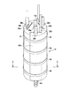
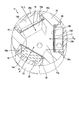
次に、電解槽11の構成を詳細に説明する。図7は電解槽の斜視図、図8は電解槽の分解斜視図、図9は図7の線C-Cに沿った電解槽の断面図である。
図7ないし図9に示すように、電解槽11は、軸方向両端が閉塞したほぼ円筒形状の中間フレーム(本体部材)22を有している。中間フレーム22の中央部に、電解液室15aが形成され、中間フレーム22の軸方向全長に亘って延びている。中間フレーム22の外周部に、それぞれ矩形状の3つの凹所58a、58b、58cが形成され、中間フレームの外周面に開口している。これらの凹所58a、58b、58cは、中間フレーム22の円周方向に等間隔で設けられている。各凹所は、中間フレーム22の軸方向全長に亘って延びているとともに、中間フレーム22の外周から中心に向かって、径方向に深さ(奥行き)を有している。
図7ないし図9に示すように、電解槽11は、軸方向両端が閉塞したほぼ円筒形状の中間フレーム(本体部材)22を有している。中間フレーム22の中央部に、電解液室15aが形成され、中間フレーム22の軸方向全長に亘って延びている。中間フレーム22の外周部に、それぞれ矩形状の3つの凹所58a、58b、58cが形成され、中間フレームの外周面に開口している。これらの凹所58a、58b、58cは、中間フレーム22の円周方向に等間隔で設けられている。各凹所は、中間フレーム22の軸方向全長に亘って延びているとともに、中間フレーム22の外周から中心に向かって、径方向に深さ(奥行き)を有している。
電解槽11は、中間フレーム22の3つの凹所58a、58b、58cに外側から中心に向かって嵌合された第1カバー(第1陽極カバー)60a、第2カバー(陰極カバー)60b、および第3カバー(第2陽極カバー)60cを有している。第1カバー60a、第2カバー60b、第3カバー60cは、電解液室15aの3面に対向して配置されている。第1、第2、第3カバー60a、60b、60cは、互いに同形状を成し、例えば、円弧状の外周面および電解液室15aに向かって開口する矩形状の開口を有する形状に形成されている。第1、第2、第3カバー60a、60b、60cの外周面は、中間フレーム22の外周面と面一に連続し、円筒形状の一部をそれぞれ構成している。このように、第1、第2、第3カバー60a、60b、60cは、後述する電極および隔膜に対して積層方向Dに凸となる湾曲した突部(外周面)を形成している。
第1カバー60aはその内面に形成された凹所により陽極室15bを形成し、第2カバー60bはその内面に形成された凹所により陰極室15cを形成し、第3カバー60cはその内面に形成された凹所により第2陽極室15dを形成している。陽極室15b、陰極室15c、および第2陽極室15dは、電解槽11内において、それぞれ軸方向と平行に延在している。
電解液室15aと第1カバー60aとの間に、第1隔膜として陰イオン交換膜16aが配置され、電解液室15aと陽極室15bを隔てている。第1陽極14は、陽極室15b内に設けられ、陰イオン交換膜16に近接、対向している。更に、第1陽極14の周縁部と第1カバー60aとの間に、水漏れを防止するためのシール材40が配置されている。シール材40は、電極の外径とほぼ等しい外径の矩形枠形状を有し、例えば、厚さ1mm程度の弾性に富むゴム材で形成されている。第1カバー60a、シール材40、第1陽極14、陰イオン交換膜16aは、第1陽極14と直交する積層方向(中間フレーム22の径方向)Dに積層されている。
電解液室15aと第2カバー60bとの間に第2隔膜として陽イオン交換膜18が配置され、電解液室15aと陰極室15cを隔てている。陰極20は、陰極室15c内に設けられ、陽イオン交換膜18に近接、対向している。更に、陰極20の周縁部と第2カバー60bとの間に矩形枠状のシール材40が配置される。第2カバー60b、シール材40、陰極20、陽イオン交換膜18は、陰極20と直交する積層方向(中間フレーム22の径方向)Dに積層されている。
電解液室15aと第3カバー60cとの間に、第1隔膜として陰イオン交換膜16bが配置され、電解液室15aと第2陽極室15dを隔てている。第2陽極17は、第2陽極室15d内に設けられ、陰イオン交換膜16bに近接、対向している。更に、第2陽極17の周縁部と第3カバー60cとの間に矩形枠状のシール材40が配置される。第3カバー60c、シール材40、第2陽極17、陰イオン交換膜16aは、第2陽極17と直交する積層方向(中間フレーム22の径方向)Dに積層されている。
陰イオン交換膜16a、16bおよび陽イオン交換膜18は同形状、例えば、細長い矩形状を成し、膜厚が約100~200μm程度に形成されている。陰イオン交換膜16a、16bおよび陽イオン交換膜18は、特定のイオンのみを通過させる特性を有している。陰イオン交換膜16a、16bおよび陽イオン交換膜18は、中間フレーム22の一面に対向して配置され、その周縁部は、中間フレーム22に密着している。なお、第1隔膜および第2隔膜は、イオン交換膜に限らず、透水性を有する多孔質膜を用いてもよい。
第1および第2陽極14、17並びに第2陰極20は同一形状を成し、例えば、厚さ1mm程度の金属製の矩形平板で形成され、前述したイオン交換膜の外径とほぼ同一の外径を有している。第1、第2陽極14、17および陰極20の各々の中央部(有効領域)には液体を通過させるための多数の微細な貫通孔が形成されている。第1陽極14、第2陽極17および陰極20は、それぞれ、その長手方向一端から突出する接続端子14b、17b、20bを有している。第1陽極14の接続端子14bおよび第2陽極17の接続端子17bは電源45のプラス側にそれぞれ接続される。陰極20の接続端子20bは、電源45のマイナス側に接続される。
中間フレーム22の軸方向の下端に、電解液室15aに連通する第1流入口ソケット34aが突設され、軸方向の上端に、電解液室15aに連通する第1流出口ソケット36aが突設されている。
第1カバー60aの軸方向の下端に、陽極室15bに連通する第2流入口ソケット34bが形成され、軸方向の上端に、陽極室15bに連通する第2流出口ソケット36bが設けられている。同様に、第2カバー60bの軸方向の下端に、陰極室15cに連通する第3流入口ソケット34cが形成され、軸方向の上端に、陰極室15cに連通する第3流出口ソケット36bが設けられている。第3カバー60cの軸方向の下端に、第2陽極室15dに連通する第4流入口ソケット34dが形成され、軸方向の上端に、第2陽極室15dに連通する第4流出口ソケット36dが設けられている。
第1カバー60aの軸方向の下端に、陽極室15bに連通する第2流入口ソケット34bが形成され、軸方向の上端に、陽極室15bに連通する第2流出口ソケット36bが設けられている。同様に、第2カバー60bの軸方向の下端に、陰極室15cに連通する第3流入口ソケット34cが形成され、軸方向の上端に、陰極室15cに連通する第3流出口ソケット36bが設けられている。第3カバー60cの軸方向の下端に、第2陽極室15dに連通する第4流入口ソケット34dが形成され、軸方向の上端に、第2陽極室15dに連通する第4流出口ソケット36dが設けられている。
図7に示すように、電解槽11の外周部には、締付け部材として、例えば、弾性に富む複数のゴムバンド50が装着されている。ゴムバンド50は、電解槽11の軸方向に適当な間隔を置いて装着される。これらのゴムバンド50の収縮力により、電解槽11の各構成部材の周縁部同士が互いに圧接され、電解液室15a、陽極室15b、陰極室15c、および第2陽極室15dの水密性を保持している。なお、シール材40は、ゴムバンド50の収縮力により圧縮され、各部材間を液密にシールする。
第1~第4流入口ソケット34a、34b、34c、34dは、電解槽11の中心軸と平行な方向に沿って、電解槽11の下端から下方に延出している。同様に、第1ないし第4流出口ソケット36a、36b、36c、36dは、電解槽11の中心軸と平行な方向に沿って、電解槽11の上端から上方に延出している。このように、円筒形状の電解槽11の軸方向両端に配置されたソケットは、円筒断面の内側に集約して配置され、締付け部材50を組立てる上で邪魔にならないようにしている。
第1、第2、第3、第4流入口ソケット34a、34b、34c、34dには、供給配管19a、接続配管54、給水配管21aがそれぞれ接続される。第1、第2、第3、第4流出口ソケット36a、36b、36c、36dには、循環配管19b、第1排水配管21b、第2排水配管21c、接続配管54がそれぞれ接続される。
以上のように構成された第2の実施形態に係る電解水生成装置によれば、電解槽11の生成水室を3室とし、2室を陽極室、1室を陰極室としている。また、電解槽11は、陰極20の面積に対して、2倍(2枚)の陽極面積を有する構成としている。これは、塩水から次亜塩素酸水を生成する電解水生成装置においては、陰極はTi材料でよく寿命も長いが、陽極はイリジウム酸化物などを触媒として形成する必要があり、この触媒寿命が電流密度により短くなることを勘案したものである。本実施形態のように陽極面積を大きく設定することにより、陽極の電流密度を低下させ、陽極触媒の寿命を長くすることができる。
なお、第1陽極室15bおよび第2陽極室15dは直列に配管接続したが、これに限らず、2つの陽極室を並列に接続してもよい。また、陽極触媒寿命以外の要因で陰極面積を増やした方が利点が得られる場合は、陰極室を2つにする構成としてもよい。また、本実施形態では同じ面積の生成室を陽極室で2室、陰極室で1室というように室数で変えたが、それぞれの生成室の面積を変えてもよい。従来の板を積層する構造では面積を変えることは難しいが、本実施形態の電解槽構造であれば生成室の室数だけでなく各生成室の面積を変えて設定することもできる。
第2の実施形態においては、電解槽11の第1、第2、第3カバー60a、60b、60cは同一形状に形成され、また、第2陽極14、第2陽極17、陰極20は同一形状に形成され、更に、複数のシール材40も同一形状に形成されている。そのため、これらの部材をそれぞれ共通の型で成形することができ、製造コストの低減を図ることができる。
本実施形態では、電解槽11は円筒形状に形成され、第1、第2、第3カバー60a、60b、60cは、電極およびイオン交換膜に対して、積層方向Dに凸となる円弧に形成されている。そのため、電解槽11の外周に装着されたゴムバンド50等の締結部材により、各構成要素を積層方向Dに押圧し容易にかつ確実に締め付けることができる。従って、ボルト止め、ねじ止め等に比較して、電解槽の組立て性を向上することができる。
更に、電解槽11の各室が円筒の軸方向(長手方向)に延びた構造を成し、かつ、給水および排水がこの軸方向に並行して設置されている。そのため、水を流す上で流水断面を確保し易く、かつ折れ曲がりなどが無いため、流水の圧力損失を極めて小さくすることができる。このため、小さい供給水圧でも電解槽11に流せる流量を大きくすることができる。また、電解槽11の外観が円筒形状であり、締付け部材を巻くことで用意にバランスよく水密に締め付けることができ、かつ、電解槽11内の水圧が上がった場合でも、円形断面であるがゆえに電解槽の歪みを小さく抑えることができる。
以上のことから、本実施形態によれば、組立て性が向上するとともに、流水による圧力損失を抑制し低圧力でも大流量の電解水を供給することができる電解セル、およびこれを備えた電解水生成装置が得られる。
以上のことから、本実施形態によれば、組立て性が向上するとともに、流水による圧力損失を抑制し低圧力でも大流量の電解水を供給することができる電解セル、およびこれを備えた電解水生成装置が得られる。
なお、上述の作用効果は、電解槽11が円筒形状の場合に限るものではなく、横断面が楕円形でも、角が丸みを帯びた三角形、矩形、多角形とした場合でも得ることができる。すなわち、電解槽の断面自体を狭めることで締結できる膨らんだ断面形状であればよい。また、構成部材の積層方向に凸となる外輪郭を有する形状であれば、種々の形状を適用することができる。締付け部材は、ゴムバンドに限るものではなく、収縮チューブや結束バンドのように電解槽の断面を狭める方向に締め付け可能な構造の部品を締付部品として用いることができる。
実施形態では3つの生成水室としたが、これに限らず、生成水室は4以上設けてもよい。この場合、電解液室を中心にその周囲に複数の生成水室を配置すればよい。また、生成水室を同じ形状で配置したが、各生成水室の形状が互いに異なる構成としてもよい。電解液は塩水、生成水は次亜塩素酸水としたが、これらに限定されることなく、種々の電解液、生成水を適用することができる。
(第3の実施形態)
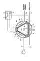
図10は、第3の実施形態に係る電解水生成装置を概略的に示す図である。
第3の実施形態によれば、電解槽11は、前述した第2の実施形態と同様に、3つの生成水室を有している。ここでは、第1カバー60aにより形成される第1生成水室は陽極室15bに割り当て、第2カバー60bにより形成される第2生成水室は陰極室15cに割り当てている。更に、第3カバー60cにより形成される第3生成水室は、第2陰極室15eとし、接続配管54により陽極室15bに直列に接続している。
図10は、第3の実施形態に係る電解水生成装置を概略的に示す図である。
第3の実施形態によれば、電解槽11は、前述した第2の実施形態と同様に、3つの生成水室を有している。ここでは、第1カバー60aにより形成される第1生成水室は陽極室15bに割り当て、第2カバー60bにより形成される第2生成水室は陰極室15cに割り当てている。更に、第3カバー60cにより形成される第3生成水室は、第2陰極室15eとし、接続配管54により陽極室15bに直列に接続している。
陽極室15b、陰極室15c、第2陰極室15eは、陰イオン交換膜16、陽イオン交換膜18a、陽イオン交換膜18bにより、それぞれ電解液室15aと仕切られている。陽極室15bに陽極14が設けられ、陰極室15cに第1陰極20aが設けられ、更に、第2陰極室15eに第2陰極20cが設けられている。
電解槽11の電解液室15aには、図示しない電解液供給部により、電解液、例えば、飽和食塩水を供給する。水供給部21は、給水源と、給水源から第2陰極室15eの下部および陰極室15cの下部に水を導く給水配管21aと、を有している。陰極室15cで生成されるアルカリ性水(水酸化ナトリウム水)は、陰極室15cの上部から第2排水配管21cを通して排水される。第2陰極室15eで生成されたアルカリ性水は、接続配管54を介して陽極室15bへ送られ、陽極室15bの生成水と混合された後、第2排水配管21cから排水される。
電流供給部23は、電源45、および調整器として機能するスイッチング回路46と、を有している。電源45のプラス側は陽極14に接続され、電源45のマイナス側は、第1陰極20aに接続されている。更に、電源45のマイナス側は、スイッチング回路46を介して第2陰極20cに接続されている。スイッチング回路46のパルス変調制御により、第2陰極20cに印加する電流の時間比率(通電時間)を調整することができる。通電時間に限らず、調整器により、第2陰極20cに印加する電流の大きさを制御するようにしてもよい。
電解槽11の他の構成および電解水生成装置の他の構成は、前述した第2の実施形態の電解水生成装置と同一としている。
電解槽11の他の構成および電解水生成装置の他の構成は、前述した第2の実施形態の電解水生成装置と同一としている。
以上のように構成された第3の実施形態によれば、電流供給部23により、第2陰極20cに印加するマイナス電位の通電時間、あるいは、電流量を調整することができる。
すなわち、第2陰極20cに全くマイナス電位を通電しない場合は、前述した第1の実施形態と同様に、陰極室15cで生成される水酸化ナトリウム成分は陽極水に混合されない状態となる。第2陰極20cに100%の比率でマイナス電位を通電する場合は、第1陰極室15cおよび第2陰極室15eで生成される水酸化ナトリウム成分の半分(第2陰極室15eで生じる分)が陽極室15bの陽極水に混合される状態となる。よって、第2陰極20cへの通電時間あるいは電流量を適時調整することで、陽極水に混合する水酸化ナトリウム量を適時制御することができる。
これにより、通常は陽極だけで生成した場合に酸性を示す陽極水(次亜塩素酸水)が水酸化ナトリウム成分の混合により中和して中性陽極水(微酸性高濃度次亜塩素酸水)を制御生成することが可能になる。純水では中和させる水酸化ナトリウムの混合比率は4割程度であるが、一般の水道水では炭酸成分などにより中和比率は小さくなり、地域毎に約1~3割、変わってしまう。本実施形態であれば、地域毎に使える水質に合わせて第2陰極への通電時間比率を変えることで、中性の陽極水を生成することが可能になる。これにより、殺菌性の高い高濃度の次亜塩素酸水を生成しても、中性のため次亜塩素酸水からの塩素ガス発生を抑制し、安全に高い殺菌性の電解水を生成することができる。
(第4の実施形態)
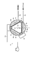
図11は、第4の実施形態に係る電解水生成装置の構成を概略的に示す図である。
第4の実施形態によれば、電解槽11は、3つの生成水室を有している。第1カバー60aにより形成される第1生成水室は陽極室15bに割り当て、第2カバー60bにより形成される第2生成水室は陰極室15cに割り当てている。更に、第3カバー60cにより形成される第3生成水室は、軟水化室15fとし、接続配管54により、陰極室15cの前段に接続している。
図11は、第4の実施形態に係る電解水生成装置の構成を概略的に示す図である。
第4の実施形態によれば、電解槽11は、3つの生成水室を有している。第1カバー60aにより形成される第1生成水室は陽極室15bに割り当て、第2カバー60bにより形成される第2生成水室は陰極室15cに割り当てている。更に、第3カバー60cにより形成される第3生成水室は、軟水化室15fとし、接続配管54により、陰極室15cの前段に接続している。
陽極室15b、陰極室15c、軟水化室15fは、陰イオン交換膜16、陽イオン交換膜18、多孔質膜38により、それぞれ電解液室15aと仕切られている。陽極室15bに陽極14が設けられ、陰極室15cに陰極20が設けられている。更に、軟水化室15fに電極は設置せず、代わりに、吸着材としてのイオン交換樹脂62を充填している。
電解槽11の電解液室15aには、図示しない電解液供給部により、電解液、例えば、飽和食塩水を供給する。水供給部21は、給水源と、給水源から陽極室15bの下部および軟水化室15fの下部に水を導く給水配管21aと、を有している。陽極14および陰極20には、図示しない電流供給部から正電圧および負電圧がそれぞれ印加される。
陽極室15bで生成される陽極水(次亜鉛塩素酸水)は、陽極室15bの上部から第1排水配管21bを通して排水される。軟水化室15fに供給された水は、イオン交換樹脂62を通水することで水中のカルシウムイオンやマグネシウムイオンなどを吸着除去された後、接続配管54を通して、陰極室15cに送られる。陰極室15cで生成される陰極水(水酸化ナトリウム水)は、第2排水配管21cを通して排水される。
電解槽11の他の構成および電解水生成装置の他の構成は、前述した第2の実施形態の電解水生成装置と同一としている。
電解槽11の他の構成および電解水生成装置の他の構成は、前述した第2の実施形態の電解水生成装置と同一としている。
以上のように構成された第4の実施形態によれば、軟水化室15fでカルシウムイオンやマグネシウムイオンなどが吸着除去された水を陰極室15cへ供給することにより、陰極室15cでアルカリ化した水中で硬度成分がスケールとして析出することを防止している。これにより、陰極室配管系統のスケール付着を抑制することができる。その他、第4の実施形態においても、前述した第1の実施形態と同様の作用効果が得られる。
なお、本実施形態では、多孔質膜38を介してわずかに電解液である塩が浸透するように構成している。電解水生成を停止している間は、静水状態で軟水化室15fの塩分濃度を5%以上に上昇させ、吸着したカルシウムやマグネシウムをナトリウムに置き換えて都度排水することで、イオン交換樹脂62の吸着性能を再生させている。このイオン交換樹脂62の再生については、多孔質膜38の代わりに隔壁を設け、従来の軟水器と同様に、別の塩水供給配管と排水配管とを軟水化室に接続し、イオン交換樹脂62を適時再生するようにしてもよい。
第3生成水室は、軟水化室に限らず、吸着材として、例えば、マンガン砂を充填した除マンガン室とし、陽極室15bの後段(下流側)に設置するようにしてもよい。陽極室15bでは酸化還元電位の高い次亜塩素酸水が生成されるため、わずかに存在する水中のマンガンを酸化して配管に析出させる可能性がある。この陽極水をマンガン砂を充填した除マンガン室に通すことで、酸化されたマンガン成分(マンガン鉄分)をマンガン砂に吸着させ除去する。これにより、陽極室に続く配管や使用環境でのマンガン析出を防止することができる。
本発明は上述した実施形態および変形例そのままに限定されるものではなく、実施段階ではその要旨を逸脱しない範囲で構成要素を変形して具体化できる。また、上記実施形態および変形例に開示されている複数の構成要素の適宜な組み合わせにより、種々の発明を形成できる。例えば、実施形態に示される全構成要素から幾つかの構成要素を削除してもよい。さらに、異なる実施形態にわたる構成要素を適宜組み合わせてもよい。
例えば、第3および第4の実施形態において、生成水室は3つに限らず、4つ以上設けてもよい。この場合、電解液室を中心にその周囲に複数の生成水室を配置すればよい。また、生成水室を同じ形状で配置したが、各生成水室の形状が互いに異なる構成としてもよい。電解液は塩水、生成水は次亜塩素酸水としたが、これらに限定されることなく、種々の電解液、生成水を適用することができる。電解槽を構成する構成部材の積層方向は、隔膜および電極と直交する方向に限定されることなく、交差する方向であればよい。
例えば、第3および第4の実施形態において、生成水室は3つに限らず、4つ以上設けてもよい。この場合、電解液室を中心にその周囲に複数の生成水室を配置すればよい。また、生成水室を同じ形状で配置したが、各生成水室の形状が互いに異なる構成としてもよい。電解液は塩水、生成水は次亜塩素酸水としたが、これらに限定されることなく、種々の電解液、生成水を適用することができる。電解槽を構成する構成部材の積層方向は、隔膜および電極と直交する方向に限定されることなく、交差する方向であればよい。
Claims (17)
- 電解液室を形成した本体部材と、前記本体部材に積層方向に沿って組み付けられ、少なくとも1つの生成室を形成したカバー部材と、を有する電解容器と、
前記電解液室と生成水室とを仕切る隔膜と、
前記電解液室を挟んで対向する一対の電極であって、少なくとも一方の電極が前記生成水室に設けられ、前記隔膜および前記生成水室と前記積層方向に並んで設けられた一対の電極と、を備え、
前記電解容器の断面の外輪郭は、前記積層方向に沿って外側に凸となる突部を有する電解セル。 - 前記電解容器は、軸方向両端が閉塞した筒状に形成され、前記電解液室および生成水室は、それぞれ前記電解容器の軸方向に延びている請求項1に記載の電解セル。
- 前記電解容器の断面の外輪郭の突部は、湾曲した突部を含んでいる請求項1又は2に記載の電解セル。
- 前記電解容器は、楕円を含む円形の断面形状を有する請求項1から3のいずれか1項に記載の電解セル。
- 前記電解容器の外輪郭の全周に亘って巻装され、前記電解容器を前記積層方向に締付ける締付け部材を備えている請求項1から4のいずれか1項に記載の電解セル。
- 前記締付け部材は、ゴムバンド、結束バンド、熱収縮チューブを含んでいる請求項5に記載の電解セル。
- 前記電解容器の軸方向の両端からそれぞれ軸方向に突出しているとともに前記電解液室あるいは生成水室に連通した、それぞれ配管を接続するための複数の配管接続部を備えている請求項1から6のいずれか1項に記載の電解セル。
- 前記複数の配管接続部は、前記電解容器の断面の外輪郭の内側に設けられている請求項7に記載の電解セル。
- 前記電解容器は、前記電解液室を挟んで前記生成水室に対向する第2生成水室を備え、前記一対の電極の一方は前記第2生成水室に配置され、前記生成水室、電解液室、第2生成水室、および一対の電極は、前記積層方向に並んでいる請求項1から8のいずれか1項に記載の電解セル。
- 前記カバー部材は、前記突部を形成した外周面と、前記外周面に対向し前記積層方向に延びる凹所と、を有し、前記本体部材は、前記積層方向に沿って前記凹所内に嵌合され、前記カバー部材により覆われている請求項2に記載の電解セル。
- 前記電解容器は、前記カバー部材の凹所に嵌合され前記本体部材と前記積層方向に並んで位置した第2カバー部材を備え、前記第2カバー部材は、前記カバー部材の外周面に連続した外周面を有し、前記電解液室に対向した第2生成水室を形成している請求項10に記載の電解セル。
- 前記電解容器は、前記電解液室を中心として、前記電解液室の周囲に設けられた3室以上の複数の生成水室を備えている請求項1から8のいずれか1項に記載の電解セル。
- 前記複数の生成水室にそれぞれ設けられた3枚以上の複数の電極を備え、
各電極、隔膜および生成水室は、それぞれ前記積層方向に沿って並んで設けられている請求項12に記載の電解セル。 - 前記電解容器の本体部材は、筒状に形成され、それぞれ本体部材の外周面に開口する複数の凹所を有し、前記電解容器は、それぞれ前記凹所に嵌合され、それぞれ前記生成水室を形成した3つ以上の複数のカバー部材を備え、各カバー部材は、前記本体部材の外周面に連続する外周面を有し、前記カバー部材の外周面は、前記突部を形成している請求項13に記載の電解セル。
- 前記複数の生成水室の少なくとも1つに陽極が設けられ、少なくとも1つの生成水室に陰極が設けられ、少なくとも1つの生成水室に水中の成分を吸着する吸着材が充填されている請求項13又は14に記載の電解セル。
- 前記吸着材は、水から硬度成分を吸着する吸着材、あるいは、マンガン成分を吸着する吸着材である請求項15に記載の電解セル。
- 請求項1から16のいずれか1項に記載の電解セルと、
前記電解液室に電解液を供給する電解液供給部と、
前記一対の電極に電圧を印加する電源と、
前記生成水室に水を供給する水供給部と、を備える電解水生成装置。
Priority Applications (2)
| Application Number | Priority Date | Filing Date | Title |
|---|---|---|---|
| JP2017529471A JP6472521B2 (ja) | 2015-07-21 | 2016-03-16 | 電解セルおよびこの電解セルを備える電解水生成装置 |
| CN201690000541.7U CN207375798U (zh) | 2015-07-21 | 2016-03-16 | 电解池和具有该电解池的电解水生成装置 |
Applications Claiming Priority (2)
| Application Number | Priority Date | Filing Date | Title |
|---|---|---|---|
| JP2015143958 | 2015-07-21 | ||
| JP2015-143958 | 2015-07-21 |
Publications (1)
| Publication Number | Publication Date |
|---|---|
| WO2017013898A1 true WO2017013898A1 (ja) | 2017-01-26 |
Family
ID=57833885
Family Applications (1)
| Application Number | Title | Priority Date | Filing Date |
|---|---|---|---|
| PCT/JP2016/058351 Ceased WO2017013898A1 (ja) | 2015-07-21 | 2016-03-16 | 電解セルおよびこの電解セルを備える電解水生成装置 |
Country Status (3)
| Country | Link |
|---|---|
| JP (1) | JP6472521B2 (ja) |
| CN (1) | CN207375798U (ja) |
| WO (1) | WO2017013898A1 (ja) |
Cited By (1)
| Publication number | Priority date | Publication date | Assignee | Title |
|---|---|---|---|---|
| JP2023029141A (ja) * | 2021-08-18 | 2023-03-03 | 株式会社ホクエツ | 無塩の微酸性電解水を使用した除鉄、除マンガン装置 |
Families Citing this family (1)
| Publication number | Priority date | Publication date | Assignee | Title |
|---|---|---|---|---|
| CN111893504B (zh) * | 2020-08-14 | 2021-10-15 | 林国尊 | 沉水式产制次氯酸水装置 |
Citations (6)
| Publication number | Priority date | Publication date | Assignee | Title |
|---|---|---|---|---|
| JPS648287A (en) * | 1987-06-29 | 1989-01-12 | Asahi Chemical Ind | Bipolar system electrolytic cell unit |
| JPH05123675A (ja) * | 1991-11-01 | 1993-05-21 | Tatsuo Okazaki | 連続通水式電解整水装置 |
| JP2005103454A (ja) * | 2003-09-30 | 2005-04-21 | Kurita Water Ind Ltd | 電気式脱イオン装置 |
| JP2011230076A (ja) * | 2010-04-28 | 2011-11-17 | Osaka Electro-Communication Univ | 電解水生成装置及び電解水生成方法 |
| US20120012466A1 (en) * | 2010-01-07 | 2012-01-19 | Sealed Air Corporation | Modular Cartridge System for Apparatus Producing Cleaning and/or Sanitizing Solutions |
| WO2014046697A1 (en) * | 2012-09-21 | 2014-03-27 | Reoxcyn Discoveries Group, Inc. | Cell for electrolyzing a liquid |
-
2016
- 2016-03-16 JP JP2017529471A patent/JP6472521B2/ja not_active Expired - Fee Related
- 2016-03-16 CN CN201690000541.7U patent/CN207375798U/zh not_active Expired - Fee Related
- 2016-03-16 WO PCT/JP2016/058351 patent/WO2017013898A1/ja not_active Ceased
Patent Citations (6)
| Publication number | Priority date | Publication date | Assignee | Title |
|---|---|---|---|---|
| JPS648287A (en) * | 1987-06-29 | 1989-01-12 | Asahi Chemical Ind | Bipolar system electrolytic cell unit |
| JPH05123675A (ja) * | 1991-11-01 | 1993-05-21 | Tatsuo Okazaki | 連続通水式電解整水装置 |
| JP2005103454A (ja) * | 2003-09-30 | 2005-04-21 | Kurita Water Ind Ltd | 電気式脱イオン装置 |
| US20120012466A1 (en) * | 2010-01-07 | 2012-01-19 | Sealed Air Corporation | Modular Cartridge System for Apparatus Producing Cleaning and/or Sanitizing Solutions |
| JP2011230076A (ja) * | 2010-04-28 | 2011-11-17 | Osaka Electro-Communication Univ | 電解水生成装置及び電解水生成方法 |
| WO2014046697A1 (en) * | 2012-09-21 | 2014-03-27 | Reoxcyn Discoveries Group, Inc. | Cell for electrolyzing a liquid |
Cited By (1)
| Publication number | Priority date | Publication date | Assignee | Title |
|---|---|---|---|---|
| JP2023029141A (ja) * | 2021-08-18 | 2023-03-03 | 株式会社ホクエツ | 無塩の微酸性電解水を使用した除鉄、除マンガン装置 |
Also Published As
| Publication number | Publication date |
|---|---|
| JP6472521B2 (ja) | 2019-02-20 |
| JPWO2017013898A1 (ja) | 2017-12-28 |
| CN207375798U (zh) | 2018-05-18 |
Similar Documents
| Publication | Publication Date | Title |
|---|---|---|
| JP2652609B2 (ja) | 電解水生成装置 | |
| US7846340B2 (en) | Water treatment system and method | |
| JP7418867B2 (ja) | 生成装置 | |
| JP4751994B1 (ja) | 有隔膜電解槽及び無隔膜電解槽を有する電解水製造装置 | |
| JP2017056376A (ja) | 電解槽およびこれを備える電解水生成装置 | |
| JP2022520341A (ja) | 水素及び酸素生成のための電気分解装置 | |
| WO2016043072A1 (ja) | 電解装置、電極ユニットおよび電解水生成方法 | |
| CN103917495A (zh) | 电纯化装置及其制造方法 | |
| JP2017057482A (ja) | 電極体、電解装置 | |
| JP2016168542A (ja) | 電解水生成装置および電解水生成方法 | |
| JP6472521B2 (ja) | 電解セルおよびこの電解セルを備える電解水生成装置 | |
| JP2018030045A (ja) | 電解水生成装置および電解水生成方法 | |
| JP6957418B2 (ja) | 電解水生成装置 | |
| KR20110082581A (ko) | 전해수 생성 장치 | |
| JP2015182008A (ja) | 電解水生成装置 | |
| WO2016114364A1 (ja) | 電解水生成装置 | |
| JP2014004547A (ja) | オゾン水生成装置 | |
| JP2003311276A (ja) | 電気式脱イオン装置 | |
| CA3125094C (en) | Chamber frame element, electrolyzer, and electrodialysis cell | |
| JP6226845B2 (ja) | 電解装置 | |
| JP3827647B2 (ja) | ガス拡散電極を備えたイオン交換膜電解槽 | |
| JP4631173B2 (ja) | 電気脱イオン装置 | |
| JP6215419B2 (ja) | 電解水生成装置、電極ユニット、および電解水生成方法 | |
| JP2003024947A (ja) | 電気透析槽 | |
| RU2658028C2 (ru) | Устройство для электрохимической активации воды и водных растворов |
Legal Events
| Date | Code | Title | Description |
|---|---|---|---|
| 121 | Ep: the epo has been informed by wipo that ep was designated in this application |
Ref document number: 16827463 Country of ref document: EP Kind code of ref document: A1 |
|
| ENP | Entry into the national phase |
Ref document number: 2017529471 Country of ref document: JP Kind code of ref document: A |
|
| NENP | Non-entry into the national phase |
Ref country code: DE |
|
| 122 | Ep: pct application non-entry in european phase |
Ref document number: 16827463 Country of ref document: EP Kind code of ref document: A1 |