WO2017010043A1 - 機能水濃度センサ - Google Patents
機能水濃度センサ Download PDFInfo
- Publication number
- WO2017010043A1 WO2017010043A1 PCT/JP2016/002885 JP2016002885W WO2017010043A1 WO 2017010043 A1 WO2017010043 A1 WO 2017010043A1 JP 2016002885 W JP2016002885 W JP 2016002885W WO 2017010043 A1 WO2017010043 A1 WO 2017010043A1
- Authority
- WO
- WIPO (PCT)
- Prior art keywords
- functional water
- light
- concentration sensor
- water concentration
- ultraviolet light
- Prior art date
Links
- XLYOFNOQVPJJNP-UHFFFAOYSA-N water Substances O XLYOFNOQVPJJNP-UHFFFAOYSA-N 0.000 title claims abstract description 326
- 238000010521 absorption reaction Methods 0.000 claims abstract description 23
- OAICVXFJPJFONN-UHFFFAOYSA-N Phosphorus Chemical compound [P] OAICVXFJPJFONN-UHFFFAOYSA-N 0.000 claims description 87
- 230000003287 optical effect Effects 0.000 claims description 31
- 230000035945 sensitivity Effects 0.000 claims description 19
- 230000004048 modification Effects 0.000 description 82
- 238000012986 modification Methods 0.000 description 82
- 238000010586 diagram Methods 0.000 description 50
- CBENFWSGALASAD-UHFFFAOYSA-N Ozone Chemical compound [O-][O+]=O CBENFWSGALASAD-UHFFFAOYSA-N 0.000 description 29
- 238000002834 transmittance Methods 0.000 description 28
- 238000005259 measurement Methods 0.000 description 18
- QWPPOHNGKGFGJK-UHFFFAOYSA-N hypochlorous acid Chemical compound ClO QWPPOHNGKGFGJK-UHFFFAOYSA-N 0.000 description 17
- 239000000463 material Substances 0.000 description 17
- 230000001954 sterilising effect Effects 0.000 description 16
- 230000006870 function Effects 0.000 description 14
- 238000004659 sterilization and disinfection Methods 0.000 description 14
- 238000002835 absorbance Methods 0.000 description 13
- 239000011521 glass Substances 0.000 description 13
- 230000008859 change Effects 0.000 description 12
- 229920005989 resin Polymers 0.000 description 9
- 239000011347 resin Substances 0.000 description 9
- 238000000862 absorption spectrum Methods 0.000 description 8
- 238000001514 detection method Methods 0.000 description 8
- 230000035699 permeability Effects 0.000 description 7
- 238000000034 method Methods 0.000 description 6
- VYPSYNLAJGMNEJ-UHFFFAOYSA-N Silicium dioxide Chemical compound O=[Si]=O VYPSYNLAJGMNEJ-UHFFFAOYSA-N 0.000 description 5
- 238000006243 chemical reaction Methods 0.000 description 5
- 230000007423 decrease Effects 0.000 description 5
- 230000007246 mechanism Effects 0.000 description 5
- 230000005540 biological transmission Effects 0.000 description 4
- 230000009467 reduction Effects 0.000 description 4
- 239000000470 constituent Substances 0.000 description 3
- 238000004332 deodorization Methods 0.000 description 3
- 230000000694 effects Effects 0.000 description 3
- 230000005284 excitation Effects 0.000 description 3
- 238000002189 fluorescence spectrum Methods 0.000 description 3
- 230000031700 light absorption Effects 0.000 description 3
- 238000005549 size reduction Methods 0.000 description 3
- 239000003795 chemical substances by application Substances 0.000 description 2
- 230000001877 deodorizing effect Effects 0.000 description 2
- -1 europium activated phosphorus Chemical class 0.000 description 2
- 230000014509 gene expression Effects 0.000 description 2
- 230000001678 irradiating effect Effects 0.000 description 2
- 239000007769 metal material Substances 0.000 description 2
- 230000008569 process Effects 0.000 description 2
- 229910052594 sapphire Inorganic materials 0.000 description 2
- 239000010980 sapphire Substances 0.000 description 2
- 239000007787 solid Substances 0.000 description 2
- 238000001228 spectrum Methods 0.000 description 2
- 239000000126 substance Substances 0.000 description 2
- 229910052684 Cerium Inorganic materials 0.000 description 1
- 229910052693 Europium Inorganic materials 0.000 description 1
- 229910052771 Terbium Inorganic materials 0.000 description 1
- NIXOWILDQLNWCW-UHFFFAOYSA-N acrylic acid group Chemical group C(C=C)(=O)O NIXOWILDQLNWCW-UHFFFAOYSA-N 0.000 description 1
- PNEYBMLMFCGWSK-UHFFFAOYSA-N aluminium oxide Inorganic materials [O-2].[O-2].[O-2].[Al+3].[Al+3] PNEYBMLMFCGWSK-UHFFFAOYSA-N 0.000 description 1
- 239000007864 aqueous solution Substances 0.000 description 1
- 230000008033 biological extinction Effects 0.000 description 1
- 239000000919 ceramic Substances 0.000 description 1
- GWXLDORMOJMVQZ-UHFFFAOYSA-N cerium Chemical compound [Ce] GWXLDORMOJMVQZ-UHFFFAOYSA-N 0.000 description 1
- 238000004042 decolorization Methods 0.000 description 1
- 230000001419 dependent effect Effects 0.000 description 1
- 239000007788 liquid Substances 0.000 description 1
- QSHDDOUJBYECFT-UHFFFAOYSA-N mercury Chemical compound [Hg] QSHDDOUJBYECFT-UHFFFAOYSA-N 0.000 description 1
- 229910052753 mercury Inorganic materials 0.000 description 1
- 229910052751 metal Inorganic materials 0.000 description 1
- 239000002184 metal Substances 0.000 description 1
- 230000001590 oxidative effect Effects 0.000 description 1
- 239000002245 particle Substances 0.000 description 1
- 229910052698 phosphorus Inorganic materials 0.000 description 1
- 238000005498 polishing Methods 0.000 description 1
- 229920003229 poly(methyl methacrylate) Polymers 0.000 description 1
- 239000004417 polycarbonate Substances 0.000 description 1
- 229920000515 polycarbonate Polymers 0.000 description 1
- 239000004926 polymethyl methacrylate Substances 0.000 description 1
- 229920006395 saturated elastomer Polymers 0.000 description 1
- 239000004065 semiconductor Substances 0.000 description 1
- 238000004904 shortening Methods 0.000 description 1
- 229920002050 silicone resin Polymers 0.000 description 1
- QWVYNEUUYROOSZ-UHFFFAOYSA-N trioxido(oxo)vanadium;yttrium(3+) Chemical compound [Y+3].[O-][V]([O-])([O-])=O QWVYNEUUYROOSZ-UHFFFAOYSA-N 0.000 description 1
- 229910052720 vanadium Inorganic materials 0.000 description 1
- 238000007740 vapor deposition Methods 0.000 description 1
Images


Classifications
-
- G—PHYSICS
- G01—MEASURING; TESTING
- G01N—INVESTIGATING OR ANALYSING MATERIALS BY DETERMINING THEIR CHEMICAL OR PHYSICAL PROPERTIES
- G01N21/00—Investigating or analysing materials by the use of optical means, i.e. using sub-millimetre waves, infrared, visible or ultraviolet light
- G01N21/17—Systems in which incident light is modified in accordance with the properties of the material investigated
- G01N21/25—Colour; Spectral properties, i.e. comparison of effect of material on the light at two or more different wavelengths or wavelength bands
- G01N21/31—Investigating relative effect of material at wavelengths characteristic of specific elements or molecules, e.g. atomic absorption spectrometry
- G01N21/33—Investigating relative effect of material at wavelengths characteristic of specific elements or molecules, e.g. atomic absorption spectrometry using ultraviolet light
-
- G—PHYSICS
- G01—MEASURING; TESTING
- G01N—INVESTIGATING OR ANALYSING MATERIALS BY DETERMINING THEIR CHEMICAL OR PHYSICAL PROPERTIES
- G01N21/00—Investigating or analysing materials by the use of optical means, i.e. using sub-millimetre waves, infrared, visible or ultraviolet light
- G01N21/62—Systems in which the material investigated is excited whereby it emits light or causes a change in wavelength of the incident light
- G01N21/63—Systems in which the material investigated is excited whereby it emits light or causes a change in wavelength of the incident light optically excited
- G01N21/64—Fluorescence; Phosphorescence
- G01N21/645—Specially adapted constructive features of fluorimeters
-
- G—PHYSICS
- G01—MEASURING; TESTING
- G01N—INVESTIGATING OR ANALYSING MATERIALS BY DETERMINING THEIR CHEMICAL OR PHYSICAL PROPERTIES
- G01N33/00—Investigating or analysing materials by specific methods not covered by groups G01N1/00 - G01N31/00
- G01N33/18—Water
-
- G—PHYSICS
- G01—MEASURING; TESTING
- G01N—INVESTIGATING OR ANALYSING MATERIALS BY DETERMINING THEIR CHEMICAL OR PHYSICAL PROPERTIES
- G01N21/00—Investigating or analysing materials by the use of optical means, i.e. using sub-millimetre waves, infrared, visible or ultraviolet light
- G01N21/62—Systems in which the material investigated is excited whereby it emits light or causes a change in wavelength of the incident light
- G01N21/63—Systems in which the material investigated is excited whereby it emits light or causes a change in wavelength of the incident light optically excited
- G01N21/64—Fluorescence; Phosphorescence
- G01N21/645—Specially adapted constructive features of fluorimeters
- G01N2021/6482—Sample cells, cuvettes
-
- G—PHYSICS
- G01—MEASURING; TESTING
- G01N—INVESTIGATING OR ANALYSING MATERIALS BY DETERMINING THEIR CHEMICAL OR PHYSICAL PROPERTIES
- G01N21/00—Investigating or analysing materials by the use of optical means, i.e. using sub-millimetre waves, infrared, visible or ultraviolet light
- G01N21/01—Arrangements or apparatus for facilitating the optical investigation
- G01N21/03—Cuvette constructions
- G01N21/031—Multipass arrangements
Definitions
- the present invention relates to a functional water concentration sensor.
- ozone is used for sterilization, deodorization, decolorization, and the like. Since ozone has a strong oxidizing power, it is necessary to control its concentration. Therefore, an ozone concentration meter that measures the ozone concentration has been developed. For example, in the light absorption ozone densitometer described in Patent Document 1, the ozone concentration is measured by irradiating the sample cell containing the sample with ultraviolet light and detecting the intensity of the transmitted light transmitted through the sample cell.
- the concentration of functional water having a predetermined function is required to be detected by a small and inexpensive sensor. If it is a small sensor, for example, it can be incorporated into a sterilization apparatus using functional water having a sterilization capability. By detecting the concentration of functional water in the sterilization apparatus, it is possible to appropriately grasp a decrease in the sterilization capability of the sterilization apparatus or the like.
- a small and inexpensive sensor cannot be realized.
- an object of the present invention is to provide a small and inexpensive functional water concentration sensor.
- a functional water concentration sensor includes a container in which functional water is placed, a light source that emits ultraviolet light, and ultraviolet light that is emitted from the light source and passes through the container.
- a fluorescent material that emits fluorescence when excited and a light receiving element that receives the fluorescence are provided, and a peak wavelength of ultraviolet light emitted from the light source is within a predetermined range including an absorption peak unique to the functional water.
- a small and inexpensive functional water concentration sensor can be provided.
- FIG. 1 is a schematic diagram showing a configuration of a functional water concentration sensor according to Embodiment 1 of the present invention.
- FIG. 2 is a schematic diagram for explaining the operation of the functional water concentration sensor according to Embodiment 1 of the present invention.
- FIG. 3 is a diagram showing a fluorescence spectrum of an example of the phosphor according to Embodiment 1 of the present invention.
- FIG. 4 is a diagram illustrating a fluorescence spectrum according to another example of the phosphor according to Embodiment 1 of the present invention.
- FIG. 5A is a diagram showing an absorption spectrum for each concentration of hypochlorous acid water according to Embodiment 1 of the present invention.
- FIG. 5B is a diagram showing the transmittance of ultraviolet light with respect to the concentration of hypochlorous acid water according to Embodiment 1 of the present invention.
- FIG. 6A is a diagram showing an absorption spectrum for each concentration of ozone water according to Embodiment 1 of the present invention.
- FIG. 6B is a diagram showing the transmittance of ultraviolet light with respect to the concentration of ozone water according to Embodiment 1 of the present invention.
- FIG. 7 is a diagram showing the relationship between the concentration of hypochlorous acid water and the transmittance of ultraviolet light when the phosphor according to Embodiment 1 of the present invention is not provided.
- FIG. 6A is a diagram showing an absorption spectrum for each concentration of ozone water according to Embodiment 1 of the present invention.
- FIG. 6B is a diagram showing the transmittance of ultraviolet light with respect to the concentration of ozone water according to Embodiment 1 of the present invention.
- FIG. 7 is a diagram showing the relationship between the
- FIG. 8 is a diagram showing the relationship between the concentration of hypochlorous acid water and the transmittance of ultraviolet light according to Embodiment 1 of the present invention.
- FIG. 9 is a schematic diagram for explaining the configuration and operation of the functional water concentration sensor according to the first modification of the first embodiment of the present invention.
- FIG. 10 is a schematic diagram for explaining the configuration and operation of the functional water concentration sensor according to the second modification of the first embodiment of the present invention.
- FIG. 11 is a schematic diagram for explaining the configuration and operation of a functional water concentration sensor according to Modification 3 of Embodiment 1 of the present invention.
- FIG. 12 is a schematic diagram for explaining the configuration and operation of a functional water concentration sensor according to Modification 4 of Embodiment 1 of the present invention.
- FIG. 13 is a schematic diagram for explaining the configuration and operation of a functional water concentration sensor according to Embodiment 2 of the present invention.
- FIG. 14 is a diagram showing the transmittance of ultraviolet light with respect to the concentration of ozone water for each optical path length in the functional water concentration sensor according to Embodiment 2 of the present invention.
- FIG. 15 is a schematic diagram for explaining the configuration and operation of a functional water concentration sensor according to Modification 1 of Embodiment 2 of the present invention.
- FIG. 16 is a schematic diagram for explaining the configuration and operation of a functional water concentration sensor according to Modification 2 of Embodiment 2 of the present invention.
- FIG. 17 is a schematic diagram for explaining the configuration and operation of a functional water concentration sensor according to Modification 3 of Embodiment 2 of the present invention.
- FIG. 18 is a schematic diagram for explaining the configuration and operation of a functional water concentration sensor according to Modification 4 of Embodiment 2 of the present invention.
- FIG. 19 is a schematic diagram for explaining the configuration and operation of a functional water concentration sensor according to Modification 5 of Embodiment 2 of the present invention.
- FIG. 20 is a schematic diagram showing a configuration of a functional water concentration sensor according to Embodiment 3 of the present invention.
- FIG. 21 is a schematic diagram illustrating a configuration of a functional water concentration sensor according to Modification 1 of Embodiment 3 of the present invention.
- FIG. 22 is a schematic diagram illustrating a configuration of a functional water concentration sensor according to the second modification of the third embodiment of the present invention.
- FIG. 23 is a schematic diagram showing a configuration of a functional water concentration sensor according to Modification 3 of Embodiment 3 of the present invention.
- each figure is a schematic diagram and is not necessarily shown strictly. Moreover, in each figure, the same code
- expressions such as substantially all or substantially the same are used. For example, the approximate match not only means that they are completely matched, but also means that they are substantially matched, that is, includes an error of about several percent. The same applies to expressions using other “abbreviations”.
- FIG. 1 is a schematic diagram showing a configuration of a functional water concentration sensor 1 according to the present embodiment.
- FIG. 2 is a schematic diagram for explaining the operation of the functional water concentration sensor 1 according to the present embodiment.
- the functional water concentration sensor 1 is a sensor that measures the concentration of the functional water 90 placed in the container 40. Specifically, the functional water concentration sensor 1 irradiates the functional water 90 with ultraviolet light, and converts the wavelength of the ultraviolet light (transmitted light) after being absorbed through the functional water 90 by the phosphor 20. The functional water concentration sensor 1 measures the concentration of the functional water 90 by detecting light after wavelength conversion (for example, visible light).
- the functional water 90 is an aqueous solution that has been provided with a reproducible and useful function by an artificial process, and the scientific basis for the process and the function has been clarified and is about to be performed. .
- the functional water 90 is hypochlorous acid water or ozone water.
- the functional water concentration sensor 1 includes a light source 10, a phosphor 20, a light receiving element 30, a container 40, and a control circuit 50.
- the functional water concentration sensor 1 is housed in a light-shielding housing in order to prevent external light from entering the light receiving element 30.
- the inner surface of the housing is formed of a material that absorbs ultraviolet light so as to absorb light (that is, stray light) that is not incident on the incident window 41 among the ultraviolet light 11 emitted from the light source 10. Also good.
- the light source 10 emits ultraviolet light 11.
- the ultraviolet light 11 is, for example, light having a peak wavelength of 350 nm or less. Details of the ultraviolet light 11 will be described later.
- the light source 10 may be capable of changing the peak wavelength of the ultraviolet light 11. Specifically, the light source 10 may emit ultraviolet light 11 having a different peak wavelength depending on the functional water 90 that is the measurement target. That is, the light source 10 may emit light having a predetermined peak wavelength as the ultraviolet light 11 based on an absorption spectrum unique to the functional water 90.
- the light source 10 is a solid light emitting element such as an LED (Light Emitting Diode) element, but is not limited thereto.
- the light source 10 may be a semiconductor laser, a small mercury lamp, or the like.
- the light source 10 is disposed close to the incident window 41 of the container 40.
- Proximity means that the distance between each other is within a predetermined range, and includes cases where they are in contact with each other.
- the light source 10 is disposed such that the distance from the incident window 41 is within 5 mm. That is, the light source 10 is arranged so that substantially all of the emitted ultraviolet light 11 enters the incident window 41, that is, the emitted ultraviolet light 11 hardly leaks outside the container 40.
- the ultraviolet light 11 from the light source 10 enters the incident window 41 substantially perpendicularly as shown in FIG.
- the distance between the light source 10 and the incident window 41 is not limited to within 5 mm, and is not particularly limited.
- the phosphor 20 is excited by the ultraviolet light 11 emitted from the light source 10 and passed through the container 40, and emits fluorescence 21. Specifically, the phosphor 20 emits fluorescence 21 as light after wavelength conversion by wavelength-converting the ultraviolet light 11 (transmitted light) after passing through the functional water 90.
- the fluorescence 21 is, for example, visible light.
- the phosphor 20 receives the ultraviolet light 11 and emits fluorescence 21 having a peak wavelength in the visible light region (380 nm to 780 nm).
- the phosphor 20 may emit light having a peak wavelength corresponding to the sensitivity of the light receiving element 30 as the fluorescence 21. Specifically, the phosphor 20 emits fluorescence 21 having a peak wavelength in a wavelength region where the sensitivity of the light receiving element 30 is high. For example, when the light receiving element 30 has high sensitivity in the green region (500 nm to 570 nm), the phosphor 20 may emit light having a peak wavelength in the range of 500 nm to 570 nm as the fluorescence 21.
- FIG. 3 and FIG. 4 are diagrams showing fluorescence spectra by an example of the phosphor 20 according to the present embodiment.
- the broken line indicates the spectrum of the ultraviolet light 11 that is the excitation light
- the solid line indicates the spectrum of the fluorescence 21.
- the phosphor 20 shown in FIG. 3 is a YPV phosphor (europium activated phosphorus / yttrium vanadate; Y (P, V) O 4 : Eu 3+ ). As shown in FIG. 3, the phosphor 20 emits fluorescence 21 (red light) having a peak wavelength at about 620 nm when receiving ultraviolet light 11 of 350 nm or less.
- fluorescence 21 red light
- the phosphor 20 shown in FIG. 4 is a LAP phosphor (cerium, terbium-activated lanthanum phosphate phosphor; LaPO 4 : Ce 3+ , Tb 3+ ). As shown in FIG. 4, the phosphor 20 emits fluorescence 21 (green light) having a peak wavelength at about 550 nm when receiving ultraviolet light 11 of 300 nm or less.
- LAP phosphor cerium, terbium-activated lanthanum phosphate phosphor
- LaPO 4 Ce 3+ , Tb 3+
- the phosphor 20 is provided, for example, on a translucent plate such as a glass plate disposed in proximity to the exit window 42.
- the phosphor 20 is contained in a resin material applied to the surface of a glass plate.
- the phosphor 20 may be dispersed and contained inside the glass plate.
- the phosphor 20 may be dispersed and contained in a plate-like ceramic (for example, alumina or the like).
- the light receiving element 30 receives the fluorescence 21. Specifically, the light receiving element 30 photoelectrically converts the received fluorescence 21 to generate an electric signal corresponding to the amount of received light (that is, intensity) of the fluorescence 21. The generated electrical signal is output to the control circuit 50.
- the light receiving element 30 has high sensitivity in a predetermined wavelength region.
- the light receiving element 30 has high sensitivity in the visible light region. That is, the light receiving element 30 has higher sensitivity to visible light than sensitivity to ultraviolet light.
- the light receiving element 30 may not have sensitivity in the ultraviolet region (380 nm or less).
- the light receiving element 30 is, for example, a photodiode, but is not limited thereto.
- the light receiving element 30 may be a phototransistor or the like.
- the light receiving element 30 is disposed close to the phosphor 20.
- the light receiving element 30 is disposed so that the distance from the phosphor 20 is within 5 mm or in contact with the phosphor 20.
- the light receiving element 30 is arranged to receive substantially all of the light traveling toward the light receiving element 30 out of the fluorescence 21 emitted from the phosphor 20.
- the distance between the light receiving element 30 and the phosphor 20 is not particularly limited to within 5 mm, and is not particularly limited.
- the container 40 is a container in which the functional water 90 is put.
- the container 40 is a cell having a bottomed cylinder such as a bottomed cylinder or a bottomed square cylinder, but is not particularly limited.
- the container 40 includes two transmission windows that transmit the ultraviolet light 11. Specifically, as shown in FIG. 1, the container 40 includes an entrance window 41 and an exit window 42.
- the incident window 41 is a window into which the ultraviolet light 11 emitted from the light source 10 enters.
- the incident window 41 is formed from a translucent member that is provided in an opening formed in the container 40 and transmits the ultraviolet light 11.
- the incident window 41 (translucent member) is made of, for example, quartz glass or sapphire glass.
- the entrance window 41 is formed of a plate-like glass whose entrance surface and exit surface are substantially flat.
- the ultraviolet light 11 enters the incident window 41 substantially vertically. Specifically, the ultraviolet light 11 is incident along the thickness direction of the plate-like glass (incident window 41). That is, the ultraviolet light 11 is incident in the normal direction of the incident surface.
- the exit window 42 is a window through which the ultraviolet light 11 incident on the container 40 exits toward the phosphor 20.
- the exit window 42 is formed from a translucent member that is provided in an opening formed in the container 40 and transmits the ultraviolet light 11.
- the exit window 42 (translucent member) is made of, for example, quartz glass or sapphire glass.
- the exit window 42 is formed of a plate-like glass whose entrance surface and exit surface are substantially flat. From the emission window 42, the ultraviolet light 11 is emitted substantially vertically. Specifically, the ultraviolet light 11 is emitted along the thickness direction of the plate-like glass (exit window 42). That is, the ultraviolet light 11 is emitted in the normal direction of the emission surface.
- the main body of the container 40 (specifically, a portion other than the two transmission windows) is formed from a material that shields (absorbs or reflects) ultraviolet light.
- the main body of the container 40 is formed from a resin material such as acrylic (PMMA) or polycarbonate (PC), or a metal material.
- the entire container 40 may be translucent to the ultraviolet light 11.
- the entire container 40 may be formed of quartz glass or the like.
- the light source 10, the container 40, the phosphor 20, and the light receiving element 30 are arranged on the substantially same straight line in this order.
- the entrance window 41 and the exit window 42 of the container 40 are also arranged on the straight line.
- the ultraviolet light 11 emitted from the light source 10 reaches the light receiving element 30 at the shortest distance, although the wavelength is converted by the phosphor 20 in the middle. Therefore, since light leakage (stray light) is prevented from occurring between the light source 10 and the light receiving element 30, the intensity of the fluorescence 21 can be detected with high accuracy, and the concentration of the functional water 90 can be measured with high accuracy. Can do.
- the container 40 may be a part of a predetermined pipe.
- the functional water 90 may flow in the container 40.
- the functional water 90 may be circulated between the container 40 and a reaction tank (not shown).
- the reaction tank is a container for exerting the function of the functional water 90.
- the functional water 90 comes into contact with an object (for example, gas such as air) in the reaction tank, thereby sterilizing and deodorizing the object.
- the functional water concentration sensor 1 can measure the concentration of the functional water 90 while the functional water 90 performs sterilization and deodorization. That is, the functional water concentration sensor 1 can be used by being incorporated in a deodorizing device or the like.
- the control circuit 50 is a controller that controls the light source 10 and the light receiving element 30.
- the control circuit 50 includes a nonvolatile memory in which a program is stored, a volatile memory that is a temporary storage area for executing the program, an input / output port, and a processor that executes the program.
- the control circuit 50 is realized by, for example, a microcomputer (microcontroller).
- the control circuit 50 measures (calculates) the concentration of the functional water 90 based on the electrical signal output from the light receiving element 30. Specifically, the control circuit 50 calculates the intensity of the fluorescence 21 based on the electrical signal, and calculates the permeability (or absorbance) of the functional water 90 based on the calculated intensity of the fluorescence 21. The control circuit 50 calculates the concentration of the functional water 90 from the calculated permeability based on the Lambert-Beer law described later. The control circuit 50 stores a table in which the intensity of the fluorescence 21 and the concentration of the functional water 90 are associated with each other in advance in the memory, and even if the concentration of the functional water 90 is determined by referring to the table. Good.
- control circuit 50 may control the turning on and off of the light source 10, the intensity and wavelength of the ultraviolet light 11, and the like. That is, the control circuit 50 causes the light source 10 to emit ultraviolet light 11 having a predetermined intensity and wavelength at a predetermined timing based on a user instruction or a program. For example, the control circuit 50 may change the intensity and wavelength of the ultraviolet light 11 based on the type of the functional water 90.
- control circuit 50 may perform feedback control of the light source 10 based on the measurement result of the concentration of the functional water 90. For example, when the amount of received light detected by the light receiving element 30 is too small, that is, when the concentration of the functional water 90 is too high, the intensity of the ultraviolet light 11 may be increased or the wavelength may be varied.
- the peak wavelength of the ultraviolet light 11 (ultraviolet light before passing through the functional water 90) emitted from the light source 10 exists within a predetermined range including an absorption peak unique to the functional water 90.
- An absorption peak is a wavelength which shows the maximum value of a light absorbency in the light absorption spectrum which the functional water 90 has. In other words, the absorption peak is the wavelength of light at which the amount of absorption by the functional water 90 is maximized.
- a is the extinction coefficient and “C” is the molar concentration of the medium.
- L is the length (that is, the optical path length) of the medium (that is, the functional water 90) through which the ultraviolet light 11 is transmitted, and in this embodiment, the distance from the entrance window 41 to the exit window 42 of the container 40. It corresponds to.
- the absorbance indicates the absorption rate of the ultraviolet light 11 by the functional water 90, and the greater the value, the greater the absorption by the functional water 90. For example, if the absorbance is “1”, all of the ultraviolet light 11 is absorbed, and if the absorbance is “0”, the ultraviolet light 11 is not absorbed at all.
- permeability has shown the transmittance
- FIG. 5A is a diagram showing an absorption spectrum for each concentration of hypochlorous acid water according to the present embodiment.
- the horizontal axis indicates the wavelength of light (ultraviolet light 11) irradiated to the functional water 90 (hypochlorous acid water), and the vertical axis indicates the absorbance of the functional water 90.
- the hypochlorous acid water has an absorption peak at about 292 nm and does not depend on its concentration, and absorbs much light in a predetermined range including the absorption peak.
- the predetermined range is a range having an absorbance equal to or higher than a predetermined ratio of the absorbance at the absorption peak.
- the predetermined ratio is, for example, 5% to 20%.
- the predetermined range of ultraviolet light that can be absorbed by hypochlorous acid water is 250 nm or more and 350 nm or less. Therefore, in the present embodiment, when the functional water 90 is hypochlorous acid water, the light source 10 emits ultraviolet light 11 having a peak wavelength in the range of 250 nm to 350 nm.
- the absorbance with respect to light of a predetermined wavelength is larger as the concentration of hypochlorous acid water is higher, and is smaller as the concentration is lower. As shown in FIG. 5A, this tendency is prominent in the vicinity of the absorption peak of about 292 nm.
- FIG. 5B is a diagram showing the transmittance of ultraviolet light with respect to the concentration of hypochlorous acid water according to the present embodiment.
- the horizontal axis represents the concentration of the functional water 90
- the vertical axis represents the transmittance of the functional water 90 with respect to the ultraviolet light 11.
- the light having a wavelength of 292 nm has a larger ratio of the change in transmittance to the concentration change than the light having a wavelength of 275 nm. That is, the closer the ultraviolet light 11 is to the absorption peak in the absorption spectrum, the easier it is to calculate the concentration of the functional water 90 based on the transmittance.
- FIG. 6A is a diagram showing an absorption spectrum for each concentration of ozone water according to the present embodiment.
- the horizontal axis indicates the wavelength of light (ultraviolet light 11) applied to the functional water 90 (ozone water), and the vertical axis indicates the absorbance of the functional water 90.
- ozone water has an absorption peak at about 260 nm without depending on its concentration, and absorbs much light in a predetermined range including the absorption peak.
- the predetermined range of ultraviolet light that can be absorbed by ozone water is 220 nm to 300 nm. Therefore, in the present embodiment, when the functional water 90 is ozone water, the light source 10 emits ultraviolet light 11 having a peak wavelength in the range of 220 nm to 300 nm.
- the absorbance with respect to a predetermined wavelength is larger as the concentration of ozone water is higher and smaller as the concentration is lower. As shown in FIG. 6A, this tendency is prominent in the vicinity of the absorption peak of about 260 nm.
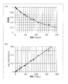
- FIG. 6B is a diagram showing the transmittance of ultraviolet light with respect to the concentration of ozone water according to the present embodiment.
- the horizontal axis represents the concentration of the functional water 90
- the vertical axis represents the transmittance of the functional water 90 with respect to the ultraviolet light 11.
- the black circles are actually measured values
- the solid line shows the exponential approximate curve of the actually measured values obtained by the least square method.
- FIG. 6B shows the transmittance with respect to the ozone concentration when light having a wavelength of 260 nm is irradiated. As shown in FIG. 6B, the higher the ozone concentration, the smaller the transmittance.
- the permeability and the concentration of the functional water 90 are dependent on each other based on the Lambert-Beer law. Therefore, by acquiring the intensity of the incident light before passing through the functional water 90 and the intensity of the transmitted light (outgoing light) after passing through the functional water 90, the functional water 90 is obtained based on (Equation 1). The absorbance (or permeability) can be calculated.
- the light source 10 when the functional water 90 is hypochlorous acid water, the light source 10 emits light having a peak wavelength in the range of 250 nm to 350 nm as the ultraviolet light 11. For example, the light source 10 emits light having a peak wavelength of 275 nm as ultraviolet light 11.
- the light source 10 When the functional water 90 is ozone water, the light source 10 emits light having a peak wavelength in the range of 220 nm or more and 300 nm or less as ultraviolet light 11. For example, the light source 10 emits light having a peak wavelength of 260 nm as the ultraviolet light 11.
- the concentration of the functional water 90 is measured based on the intensity before incidence of the ultraviolet light 11 and the intensity after transmission. Specifically, instead of directly detecting the ultraviolet light 11 that is transmitted light, the light receiving element 30 detects the converted fluorescence 21 after being converted into the fluorescence 21 by the phosphor 20. In the present embodiment, the concentration of the functional water 90 is measured by using the intensity of the fluorescence 21 instead of the intensity of the transmitted light (ultraviolet light 11).
- FIG. 7 is a diagram showing a relationship between the concentration of hypochlorous acid water and the transmittance of the ultraviolet light 11 when the phosphor 20 according to the present embodiment is not provided.
- black circles and black triangles are actually measured values
- a solid line is an exponential approximate curve of the actually measured values obtained by the least square method.
- FIG. 7 the transmitted light (ultraviolet light 11) emitted from the emission window 42 without using the phosphor 20 was detected using a photodiode having sensitivity in the ultraviolet region.
- (A) of FIG. 7 has shown the case where the peak wavelength of the ultraviolet light 11 is 275 nm, and is the same as the graph shown to FIG. 5B.
- FIG. 7B is a graph in which the vertical axis of the graph shown in FIG.
- the permeability is expressed as an exponential function of concentration as shown in (Equation 1). For this reason, the relationship between the transmittance and the density is represented by a straight line on the logarithmic graph. As shown in FIG. 7B, the actual measurement values (black circles and black triangles) substantially coincide with the approximate line, and it can be seen that the concentration of the functional water 90 can be measured by detecting the ultraviolet light 11.
- FIG. 8 is a diagram showing the relationship between the concentration of hypochlorous acid water and the transmittance of ultraviolet light according to the present embodiment.
- the black squares are measured values
- the solid line is an exponential approximation curve of the measured values obtained by the least square method.
- a YPV phosphor is used as the phosphor 20.
- the phosphor 20 emits fluorescence 21 having an intensity corresponding to the intensity of the ultraviolet light 11 that is excitation light.
- the ultraviolet light 11 that is excitation light and the fluorescence 21 are in a proportional relationship. Therefore, the control circuit 50 calculates the transmittance of the ultraviolet light 11 by converting the intensity of the fluorescence 21 detected by the light receiving element 30 into the intensity of the ultraviolet light 11.
- FIG. 8A shows a case where the peak wavelength of the ultraviolet light 11 is 275 nm
- FIG. 8B shows a graph obtained by converting the graph shown in FIG. 8A into a logarithmic graph.
- the measured values black squares
- solid line the approximate curve
- the concentration of the functional water 90 can be measured by detecting the fluorescence 21. That is, it is understood that there is no need to detect the ultraviolet light 11 directly.
- the functional water concentration sensor 1 includes the container 40 in which the functional water 90 is placed, the light source 10 that emits the ultraviolet light 11, and the ultraviolet light that is emitted from the light source 10 and passes through the container 40.
- a phosphor 20 that emits fluorescence 21 when excited by the light 11 and a light receiving element 30 that receives the fluorescence 21 are included.
- the peak wavelength of the ultraviolet light 11 emitted from the light source 10 is a predetermined value including an absorption peak unique to the functional water 90. Exists in the range.
- the phosphor 20 emits fluorescence 21 by converting the wavelength of the ultraviolet light 11, and the light receiving element 30 receives the fluorescence 21 emitted by the phosphor 20.
- the fluorescence 21 is light having a longer wavelength than the ultraviolet light 11 and is, for example, visible light. For this reason, as the light receiving element 30, it is not necessary to have sensitivity in the ultraviolet region, and an inexpensive photodiode having sensitivity in the visible light region can be used.
- the functional water concentration sensor 1 can be miniaturized and long-life.
- the ultraviolet light 11 emitted from the light source 10 has, for example, an absorption spectrum specific to the functional water 90 so that the peak wavelength is included within a predetermined range including an absorption peak specific to the functional water 90.
- the concentration of the functional water 90 is measured by detecting the change in the intensity of the ultraviolet light 11 by absorbing the ultraviolet light 11 with the functional water 90. For this reason, it is not necessary to add to the functional water 90 a substance intended to measure the concentration of a detection agent or the like. Therefore, since the functional water 90 does not react with the detection agent to cause a chemical change, even the functional water 90 after measuring the concentration (after irradiation with the ultraviolet light 11) exhibits its original function. be able to. That is, since the functional water concentration sensor 1 can measure the concentration while maintaining the function of the functional water 90, it can be incorporated in a device that uses the functional water 90.
- the functional water 90 when the functional water 90 is a liquid having a sterilizing ability such as hypochlorous acid water, the sterilizing ability of the functional water 90 is not lost, so that the functional water 90 can be used for sterilization as it is.
- concentration measurement and sterilization can be performed while circulating the functional water 90, feedback control such as reflecting the concentration measurement result in sterilization becomes possible.
- the functional water concentration sensor 1 can be incorporated into a device such as a sterilization apparatus.
- the concentration of the functional water 90 can be raised and functions, such as disinfection, can fully be exhibited. Further, by preventing the concentration of the functional water 90 from becoming too high by feedback control, generation of harmful gas or odor gas can be prevented.
- the phosphor 20 emits light having a peak wavelength corresponding to the sensitivity of the light receiving element 30 as the fluorescence 21.
- the region where the sensitivity of the light receiving element 30 is high can be used effectively, the range of the detectable light amount is increased. Accordingly, the measurable concentration range can be increased, or the concentration measurement accuracy can be increased.
- the phosphor 20 fluoresces evenly in all directions. That is, since the fluorescence 21 emitted from the phosphor 20 is emitted in all directions, when the phosphor 20 and the light receiving element 30 are separated from each other, the amount of the fluorescence 21 received by the light receiving element 30 is reduced.
- the light receiving element 30 is disposed close to the phosphor 20.
- the amount of light incident on the light receiving element 30 among the fluorescence 21 emitted from the phosphor 20 can be increased, so that even when the fluorescence 21 is weak, it can be detected. Accordingly, the measurable concentration range can be increased. Further, light (stray light) that travels in the housing (not shown) of the functional water concentration sensor 1 without being incident on the light receiving element 30 can be reduced. For this reason, it is possible to suppress detection errors caused by stray light entering the light receiving element 30, and to detect the fluorescence 21 with high accuracy.
- the light source 10, the container 40, the phosphor 20, and the light receiving element 30 are arranged on substantially the same straight line in this order.
- the traveling direction of the ultraviolet light 11 or the fluorescence 21 since it is not necessary to change the traveling direction of the ultraviolet light 11 or the fluorescence 21 by reflection or refraction, it is not necessary to provide a member such as a lens or a mirror, and downsizing and cost reduction can be realized. . Further, when the light traveling direction is changed by a member such as a lens or a mirror, the amount of the fluorescence 21 incident on the light receiving element 30 may decrease due to generation of stray light or absorption of light by the member. On the other hand, since the functional water concentration sensor 1 does not include a lens or a mirror, the decrease in the amount of the fluorescence 21 incident on the light receiving element 30 can be suppressed, and the concentration of the functional water 90 can be accurately measured. .
- the container 40 includes an incident window 41 on which the ultraviolet light 11 emitted from the light source 10 enters, and the ultraviolet light 11 from the light source 10 enters the incident window 41 substantially perpendicularly.
- the concentration of the functional water 90 can be measured with high accuracy.
- FIG. 9 is a schematic diagram for explaining the configuration and operation of the functional water concentration sensor 1a according to the first modification of the present embodiment.
- the functional water concentration sensor 1a according to the present modification is different from the functional water concentration sensor 1 shown in FIG. 1 in that a slit portion 60 is newly provided.
- the slit part 60 is provided between the light source 10 and the incident window 41 and restricts the irradiation range of the ultraviolet light 11. Specifically, the slit portion 60 has an opening that has substantially the same shape as the incident window 41.
- the slit part 60 is a board provided with an opening (slit), for example. The slit portion 60 is provided so that the opening and the incident window 41 substantially coincide when viewed from the light source 10.
- the slit portion 60 is formed of a material that shields (reflects or absorbs) the ultraviolet light 11.
- the slit part 60 is formed from the same material as the main body of the container 40, for example.
- the light emitted from the light source 10 other than the opening among the ultraviolet light 11 is shielded by the slit portion 60 and is contained in the container 40. Does not progress.
- the light that has passed through the opening enters the entrance window 41, passes through the functional water 90, and exits from the exit window 42. In this way, stray light caused by irradiating unnecessary areas with ultraviolet light can be reduced, and detection accuracy can be increased.
- FIG. 10 is a schematic diagram for explaining the configuration and operation of the functional water concentration sensor 1b according to the second modification of the present embodiment.
- the functional water concentration sensor 1b according to this modification is different from the functional water concentration sensor 1 shown in FIG. 1 in that a lens unit 61 is newly provided.
- the lens unit 61 is provided between the light source 10 and the incident window 41 and suppresses the divergence of the ultraviolet light 11.
- the lens unit 61 is, for example, a condensing lens that condenses the phosphor 20, or a collimating lens that emits the ultraviolet light 11 as parallel light.
- the lens unit 61 is made of, for example, translucent quartz glass.
- the amount of the ultraviolet light 11 that passes through the functional water 90 can be increased, so that the measurable concentration range can be increased.
- the concentration measurement accuracy can be increased.
- FIG. 11 is a schematic diagram for explaining the configuration and operation of a functional water concentration sensor 1c according to Modification 3 of the present embodiment.
- the functional water concentration sensor 1 c Compared with the functional water concentration sensor 1 shown in FIG. 1, the functional water concentration sensor 1 c according to this modification is provided with a phosphor 20 c instead of the phosphor 20 and emits instead of the emission window 42 of the container 40. The difference is that the window 42c is provided.
- the phosphor 20 c is provided in the exit window 42 c of the container 40.
- the exit window 42c is formed of a phosphor-containing glass containing the phosphor 20c.
- the emission window 42c contains phosphor particles dispersedly.
- the functional water concentration sensor 1c since the phosphor 20c and the emission window 42c are shared, the distance between the container 40 and the light receiving element 30 can be shortened. it can. Thereby, the functional water concentration sensor 1c can be reduced in size. Moreover, since the stray light of the fluorescence 21 emitted from the emission window 42c can be reduced, the detection accuracy can be increased.
- FIG. 12 is a schematic diagram for explaining the configuration and operation of a functional water concentration sensor 1d according to Modification 4 of the present embodiment.
- the functional water concentration sensor 1d according to this modification is different from the functional water concentration sensor 1 shown in FIG. 1 in that a phosphor 20d is provided instead of the phosphor 20.
- the phosphor 20d is provided on the surface of the light receiving element 30. Specifically, the phosphor 20d is contained in a resin material applied to the surface of the light receiving element 30.
- the resin material is a light-transmitting material such as a silicone resin.
- the functional water concentration sensor 1d since the phosphor 20d is provided on the surface of the light receiving element 30, it is possible to increase the amount of received light of the fluorescence 21 emitted from the phosphor 20d. it can. Thereby, since the stray light of the fluorescence 21 emitted from the emission window 42c can be reduced, the detection accuracy can be increased. Moreover, since the distance between the container 40 and the light receiving element 30 can be shortened, the functional water concentration sensor 1d can be reduced in size.
- Embodiment 2 Next, the functional water concentration sensor according to Embodiment 2 will be described with reference to FIG. In the following, differences from the first embodiment will be mainly described, and description of the same points as those of the first embodiment will be omitted or simplified.
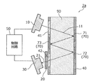
- FIG. 13 is a schematic diagram for explaining the configuration and operation of the functional water concentration sensor 2 according to the present embodiment. As shown in FIG. 13, the functional water concentration sensor 2 is different from the functional water concentration sensor 1 according to Embodiment 1 in that a new reflection unit 70 is provided.
- the reflection unit 70 is an example of a first reflection unit that is provided inside the container 40 and reflects the ultraviolet light 11.
- the reflection unit 70 specularly reflects the ultraviolet light 11.
- the reflection unit 70 reflects the ultraviolet light 11 emitted from the light source 10 and passed through the incident window 41 toward the phosphor 20.
- the reflected ultraviolet light 11 passes through the emission window 42 and is applied to the phosphor 20 to excite the phosphor 20.
- the phosphor 20 is excited to emit fluorescence 21, and the fluorescence 21 enters the light receiving element 30.
- the optical path length of the ultraviolet light 11 becomes about twice the width of the container 40 as shown in FIG. 13.
- the reflection part 70 is the inner surface of the container 40.
- the reflecting portion 70 is formed by performing a mirror finish on the inner surface of the container 40.
- the reflecting portion 70 is formed by polishing the inner surface to make a mirror surface.
- the reflective portion 70 is formed by forming a metal vapor deposition film or the like on the inner surface.
- the reflection unit 70 may be a separate body from the container 40. That is, the reflection part 70 may be a reflection plate disposed at a predetermined position of the container 40.
- the reflection unit 70 may be, for example, a glass plate or a resin plate whose surface is mirror-finished.
- the reflection part 70 is fixed to the inner surface of the container 40.
- FIG. 14 is a diagram showing the transmittance of the ultraviolet light 11 with respect to the concentration of ozone water for each optical path length in the functional water concentration sensor 2 according to the present embodiment.
- FIG. 14B is an enlarged view of the ozone concentration range of 0 to 0.05 mg / L and the transmittance of 0.96 to 1 (dotted line frame in FIG. 14A). is there.
- the longer the optical path length the longer the time for which the ultraviolet light 11 is transmitted and the longer the time for contact with the functional water 90. For this reason, the light quantity of the ultraviolet light 11 absorbed by the functional water 90 also increases and the transmittance decreases.
- the functional water concentration sensor 2 according to the present embodiment further includes the reflection unit 70 that is provided inside the container 40 and reflects the ultraviolet light 11.
- the optical path length of the ultraviolet light 11 can be increased by reflecting the ultraviolet light 11 inside the container 40 by the reflecting portion 70 provided inside the container 40. For this reason, even if the concentration of the functional water 90 is low and the absorbance is low, a large amount of the ultraviolet light 11 is absorbed by increasing the optical path length of the ultraviolet light 11, so that a change in the intensity of the ultraviolet light 11 is received. It can be detected by the element 30. That is, the measurement range of the concentration of the functional water 90 can be increased. Thus, the measurable concentration range can be increased without increasing the size of the functional water concentration sensor 2.
- the reflection part 70 is the inner surface of the container 40.
- the inner surface of the container 40 is used as the reflecting portion 70, a separate member is not required and the cost can be reduced. Moreover, compared with the case where a reflecting plate or the like is provided as a separate member, the space in the container 40 can be used effectively, and for example, a longer optical path length can be ensured.
- the functional water concentration sensor 2 may not include the phosphor 20. That is, the light receiving element 30 is a photodiode having sensitivity in the ultraviolet region, and may directly detect the ultraviolet light 11 transmitted through the functional water 90. Even in this case, according to the present embodiment, the measurable concentration range can be increased and the measurement accuracy can be increased without increasing the size. That is, the functional water concentration sensor 2 can be reduced in size, increased in accuracy, and increased in sensitivity.
- FIG. 15 is a schematic diagram for explaining the configuration and operation of the functional water concentration sensor 2a according to the first modification of the present embodiment.
- the functional water concentration sensor 2a according to the present modification is different from the functional water concentration sensor 2 shown in FIG.
- the plurality of reflecting portions 70 are arranged so as to multiple-reflect the ultraviolet light 11.
- FIG. 15 shows an example where the functional water 90 is flowing in the container 40, that is, an example in which the container 40 is a part of piping that forms the flow path of the functional water 90.
- the shape of the container 40 ie, the shape of piping, is a cylinder or a square tube, for example, it is not specifically limited.
- the functional water 90 flows in the vertical direction on the paper surface in FIG. This also applies to the following modifications 2 to 5.
- the functional water concentration sensor 2 a includes three reflecting portions 71 to 73 as the plurality of reflecting portions 70.
- the functions and materials of the reflecting portions 71 to 73 are the same as those of the reflecting portion 70 shown in FIG.
- the reflection parts 71 and 72 are provided on the surface of the inner surface of the container 40 facing the light source 10 and the light receiving element 30, and the reflection part 73 is the same side of the inner surface of the container 40 as the light source 10 and the light receiving element 30. It is provided on the surface.
- the reflection unit 71 reflects the ultraviolet light 11 emitted from the light source 10 and having passed through the incident window 41 toward the reflection unit 73.
- the reflection unit 73 reflects the ultraviolet light 11 reflected by the reflection unit 71 toward the reflection unit 72.
- the reflection part 72 reflects the ultraviolet light 11 reflected by the reflection part 73 toward the phosphor 20.
- the ultraviolet light 11 reflected by the reflector 72 passes through the emission window 42 and is irradiated on the phosphor 20 to excite the phosphor 20.
- the functional water concentration sensor 2a includes the plurality of first reflection units 70, and the plurality of reflection units 70 are arranged so as to multiply reflect the ultraviolet light 11.
- the optical path length of the ultraviolet light 11 traveling inside the container 40 can be made longer.
- the concentration of thinner functional water 90 can be measured. That is, high sensitivity of the functional water concentration sensor 2a can be realized.
- the entire inner surface of the container 40 may be mirrored.
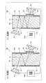
- FIG. 16 is a schematic diagram for explaining the configuration and operation of a functional water concentration sensor 2b according to Modification 2 of the present embodiment.
- the arrangement positions or orientations of the light source 10 and the light receiving element 30 are variable according to the concentration of the functional water 90.
- FIG. 16A shows the case where the concentration of the functional water 90 is high
- FIG. 16B shows the case where the concentration of the functional water 90 is low.
- the functional water concentration sensor 2b according to this modification is different from the functional water concentration sensor 2 shown in FIG. 13 in that a control circuit 50b is provided instead of the control circuit 50.
- a reflection portion 70 is provided on the entire inner surface of the container 40.
- the reflection part 70 does not need to be provided in the whole inner surface of the container 40, and should just be provided in the range to which the ultraviolet light 11 is irradiated.
- control circuit 50b further changes the arrangement position or orientation of at least one of the light source 10 and the light receiving element 30 according to the concentration of the functional water 90.
- At least one of the light source 10 and the light receiving element 30 is provided with a movable mechanism (not shown) such as an actuator.
- the control circuit 50b changes the arrangement position or orientation of at least one of the light source 10 and the light receiving element 30 via the actuator.
- the control circuit 50 b changes the optical path length from the light source 10 to the light receiving element 30.
- the optical path length corresponds to the length that the ultraviolet light 11 passes through the functional water 90, that is, the distance from the incidence window 41 entering the functional water 90 to the incidence window 42.
- the control circuit 50b determines the arrangement position or orientation of the light source 10 or the light receiving element 30 so that the optical path length is shortened as shown in FIG. change.
- the control circuit 50b changes the direction of the light source 10 so that the number of reflections of the ultraviolet light 11 within the container 40 is reduced.
- the control circuit 50b increases the incident angle of the ultraviolet light 11 emitted from the light source 10 with respect to the incident window 41, that is, the ultraviolet light 11 is incident on the incident window 41 more obliquely. The direction of the light source 10 is changed.
- the control circuit 50b changes the direction of the light receiving element 30 in accordance with the direction of the ultraviolet light 11 emitted from the emission window 42. Specifically, the control circuit 50b changes the direction of the light receiving element 30 so that the ultraviolet light 11 is perpendicularly incident on the light receiving surface.
- the phosphor 20 is provided, and the light receiving element 30 receives the fluorescence 21 instead of the ultraviolet light 11. Since the phosphor 20 emits the fluorescence 21 in all directions, the control circuit 50b may not change the direction of the light receiving element 30.
- the control circuit 50b changes the arrangement position or orientation of the light source 10 or the light receiving element 30 so that the optical path length becomes longer as shown in FIG.
- the control circuit 50b changes the direction of the light source 10 so that the number of reflections of the ultraviolet light 11 in the container 40 increases.
- the control circuit 50b makes the incident angle of the ultraviolet light 11 emitted from the light source 10 with respect to the incident window 41 smaller, that is, the ultraviolet light 11 enters the incident window 41 at an angle closer to the vertical.
- the control circuit 50b may change the direction of the light receiving element 30, but as described above, in the present modification, the fluorescent light 21 is detected, and thus the control circuit 50b need not be changed.
- the control circuit 50b can optimally measure the concentration in the vicinity of the predicted value of the optical path length from the light source 10 to the light receiving element 30 based on the predicted value (for example, the previous measured value) of the functional water 90.
- the arrangement position or orientation of the light source 10 or the light receiving element 30 is changed so that the optical path length becomes a proper one.
- the concentration of the functional water 90 is too high, most of the ultraviolet light 11 is absorbed, so that the light receiving element 30 can hardly receive the fluorescence 21.
- the absorption of the ultraviolet light 11 by the functional water 90 can be suppressed by shortening the optical path length, and the fluorescence 21 can be received by the light receiving element 30. it can. Thereby, the density
- the concentration of the functional water 90 is too low, the ultraviolet light 11 is hardly absorbed, and the light amount of the fluorescence 21 detected by the light receiving element 30 is substantially the same as when the functional water 90 is not present. Alternatively, it may be saturated beyond the detection range of the light receiving element 30. In this case, by increasing the optical path length, the absorption of the ultraviolet light 11 by the functional water 90 can be promoted, and the light receiving element 30 can receive the fluorescent light 21 with an appropriate amount of light. Thereby, the density
- the arrangement position or orientation of at least one of the light source 10 and the light receiving element 30 is further changed according to the concentration of the functional water 90, so that the light source 10 A control circuit 50b for changing the optical path length to the light receiving element 30 is provided.
- the measurement accuracy of the concentration of the functional water 90 can be improved, and the measurement range can be enlarged.
- FIG. 17 is a schematic diagram for explaining the configuration and operation of a functional water concentration sensor 2c according to Modification 3 of the present embodiment.
- the functional water concentration sensor 2c according to this modification is different from the functional water concentration sensor 2 shown in FIG. 13 in that a slit portion 60c is newly provided.
- the slit portion 60 c is provided between the light source 10 and the incident window 41 and restricts the irradiation range of the ultraviolet light 11.
- the slit portion 60c is an example of a collimating portion that converts the ultraviolet light 11 into parallel light. Specifically, the ultraviolet light 11 emitted from the light source 10 is emitted as parallel light by passing through the opening of the slit portion 60c.
- the slit part 60c is, for example, a plate provided with an opening (slit).
- the slit portion 60c is formed of a material that shields (reflects or absorbs) the ultraviolet light 11.
- the slit part 60c is formed from the same material as the main body of the container 40, for example.
- the ultraviolet light 11 is converted into parallel light by the slit portion 60c, so that the attenuation of the ultraviolet light 11 can be suppressed. Can improve the efficiency of use. As a result, the measurable concentration range can be increased, or the concentration measurement accuracy can be increased. Moreover, in this modification, since a collimating mechanism can be implement
- FIG. 18 is a schematic diagram for explaining the configuration and operation of a functional water concentration sensor 2d according to Modification 4 of the present embodiment.
- the functional water concentration sensor 2d according to this modification is different from the functional water concentration sensor 2 shown in FIG. 13 in that a lens unit 61d is newly provided.
- the lens part 61d is provided between the light source 10 and the incident window 41, and limits the irradiation range of the ultraviolet light 11.
- the lens unit 61d is an example of a collimating unit that converts the ultraviolet light 11 into parallel light. Specifically, the ultraviolet light 11 emitted from the light source 10 is emitted as parallel light by passing through the lens unit 61d.
- the lens part 61d is a collimating lens, and is formed of, for example, a light-transmitting quartz glass.
- the ultraviolet light 11 is converted into parallel light by the lens unit 61d, so that the attenuation of the ultraviolet light 11 can be suppressed. Can improve the efficiency of use. As a result, the measurable concentration range can be increased, or the concentration measurement accuracy can be increased. Moreover, in this modification, since a collimating mechanism is realizable with a simple structure, size reduction and cost reduction of the functional water concentration sensor 2d are realizable.
- FIG. 19 is a schematic diagram for explaining the configuration and operation of a functional water concentration sensor 2e according to Modification 5 of the present embodiment.
- the functional water concentration sensor 2 e Compared with the functional water concentration sensor 2 shown in FIG. 13, the functional water concentration sensor 2 e according to this modification includes a plurality of sets of light sources 10 and light receiving elements 30, and a control circuit 50 e instead of the control circuit 50. It differs from the point to prepare.
- a plurality of light sources 10 and a plurality of light receiving elements 30 are arrayed.
- the plurality of light sources 10 are arrayed one-dimensionally along the direction in which the functional water 90 flows.
- the plurality of light sources 10 may be arrayed in two dimensions or three dimensions. The same applies to the plurality of light receiving elements 30.
- the functional water concentration sensor 2 e includes light sources 10 e 1 and 10 e 2 as the plurality of light sources 10.
- the functional water concentration sensor 2 e includes light receiving elements 30 e 1 and 30 e 2 as the plurality of light receiving elements 30.
- the light sources 10e1 and 10e2 and the light receiving elements 30e1 and 30e2 have the same functions as the light source 10 and the light receiving element 30, respectively.
- the light source 10e1 and the light receiving element 30e1 are associated with each other, and the light source 10e2 and the light receiving element 30e2 are associated with each other.
- the light source 10e1 and the light receiving element 30e1 form a set (for example, a first set), and the light source 10e2 and the light receiving element 30e2 form another set (for example, a second set).
- the ultraviolet light 11 emitted from the light source 10e1 enters the light receiving element 30e1
- the ultraviolet light 11 emitted from the light source 10e2 enters the light receiving element 30e2.
- the plurality of sets of the light source 10 and the light receiving element 30 are arranged so that the optical path lengths from the light source 10 to the corresponding light receiving element 30 are different from each other. As shown in FIG. 19, the optical path length of the set (first set) of the light source 10e1 and the light receiving element 30e1 is longer than the optical path length of the set (second set) of the light source 10e2 and the light receiving element 30e2.
- the control circuit 50e selectively changes a plurality of sets of the light source 10 and the light receiving element 30 according to the concentration of the functional water 90 in addition to the function of the control circuit 50. Thereby, the control circuit 50e changes the optical path length according to the concentration of the functional water 90.
- the control circuit 50e selects a set (first set) of the light source 10e1 and the light receiving element 30e1 having a long optical path length. Conversely, when the concentration of the functional water 90 is low, the control circuit 50e selects a set (second set) of the light source 10e2 and the light receiving element 30e2 having a short optical path length.
- the functional water concentration sensor 2e includes a plurality of sets of the light source 10 and the light receiving element 30, and the plurality of sets of the light source 10 and the light receiving element 30 extends from the light source 10 to the corresponding light receiving element 30.
- the functional water concentration sensor 2e is further provided with a control circuit 50e that selectively changes a plurality of sets according to the concentration of the functional water 90.
- an appropriate optical path length can be obtained by selecting an appropriate set according to the density. You can choose. Therefore, the measurement accuracy of the concentration of the functional water 90 can be improved, and the measurement range can be increased.
- Embodiment 3 Next, a functional water concentration sensor according to Embodiment 3 will be described with reference to FIG. In the following, differences from the first embodiment will be mainly described, and description of the same points as those of the first embodiment will be omitted or simplified.
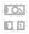
- FIG. 20 is a schematic diagram showing the configuration of the functional water concentration sensor 3 according to the present embodiment.
- FIG. 20A is a cross-sectional view of the functional water concentration sensor 3 and shows a cross section orthogonal to the direction in which the functional water 90 flows in the container 40 constituting a part of the piping.
- FIG. 20B shows a cross section taken along line XX-XX in FIG. That is, the functional water 90 flows in the depth direction of the paper surface in (a), and flows in the vertical direction of the paper surface in (b) (see the white arrow).
- the functional water concentration sensor 3 is different from the functional water concentration sensor 1 according to the first embodiment in that a new reflection unit 80 is provided.
- the reflection unit 80 is an example of a second reflection unit that has a reflection surface on which the phosphor 20 is provided and reflects the fluorescence 21 toward the light receiving element 30 by the reflection surface.
- the reflection unit 80 is provided outside the container 40.
- the reflector 80 is a reflector disposed outside the container 40.
- the reflection unit 80 is, for example, a glass plate or a resin plate in which at least one main surface (reflection surface) is mirror-finished. A resin material containing the phosphor 20 is applied to the reflection surface of the reflection unit 80.
- the present invention is not limited to this.
- a glass plate including the phosphor 20 may be attached to the reflecting surface.
- the functional water concentration sensor 3 further includes a reflection surface on which the phosphor 20 is provided, and is provided outside the container 40.
- the light receiving element 30 receives the fluorescence 21 by the reflection surface.
- the reflection part 80 which reflects toward is provided.
- the fluorescence 21 emitted from the phosphor 20 is emitted to the exit window 42 side and does not enter the light receiving element 30.
- the reflecting portion 80 since the reflecting portion 80 reflects the fluorescence 21 toward the light receiving element 30, more fluorescence 21 can be incident on the light receiving element 30. Thereby, the fluorescence 21 emitted from the phosphor 20 can be used effectively. Therefore, even if the intensity of the ultraviolet light 11 is weak and the intensity of the fluorescence 21 is weak, the light receiving element 30 can receive a large amount of light, so that the concentration of the functional water 90 can be measured. That is, the measurable range of the concentration of the functional water 90 can be increased.
- FIG. 21 is a schematic diagram illustrating a configuration of a functional water concentration sensor 3a according to the first modification of the present embodiment. Specifically, (a) of FIG. 21 shows a cross section orthogonal to the direction in which the functional water 90 flows in the container 40 constituting a part of the piping of the functional water concentration sensor 3a. The cross section in the XXI-XXI line of (a) is shown.
- the functional water concentration sensor 3a according to this modification is different from the functional water concentration sensor 3 shown in FIG. 20 in that a slit portion 60c is newly provided.
- the slit portion 60c is the same as that shown in the third modification of the second embodiment.
- the ultraviolet light 11 is converted into parallel light by the slit portion 60c, so that the attenuation of the ultraviolet light 11 can be suppressed. Can improve the efficiency of use. As a result, the measurable concentration range can be increased, or the concentration measurement accuracy can be increased. Moreover, in this modification, since a collimating mechanism can be implement
- FIG. 22 is a schematic diagram illustrating a configuration of a functional water concentration sensor 3b according to the second modification of the present embodiment. Specifically, (a) of FIG. 22 shows a cross section orthogonal to the direction in which the functional water 90 flows in the container 40 constituting a part of the piping of the functional water concentration sensor 3b. The cross section in the XXII-XXII line of (a) is shown.
- the functional water concentration sensor 3b according to this modification is different from the functional water concentration sensor 3 shown in FIG. 20 in that a lens unit 61d is newly provided.
- the lens unit 61d is the same as that shown in the fourth modification of the second embodiment.
- the ultraviolet light 11 is converted into parallel light by the lens unit 61d, so that the attenuation of the ultraviolet light 11 can be suppressed. Can improve the efficiency of use. As a result, the measurable concentration range can be increased, or the concentration measurement accuracy can be increased. Moreover, in this modification, since a collimating mechanism can be realized with a simple configuration, the functional water concentration sensor 3b can be reduced in size and cost.
- FIG. 23 is a schematic diagram showing a configuration of a functional water concentration sensor 3c according to Modification 3 of the present embodiment. Specifically, FIG. 23 shows a cross section orthogonal to the direction in which the functional water 90 flows in the container 40 constituting a part of the piping of the functional water concentration sensor 3c.
- the functional water concentration sensor 3c according to this modification is different from the functional water concentration sensor 3 shown in FIG. 20 in that a reflective portion 80c is provided instead of the reflective portion 80.
- the reflection part 80c is a concave mirror.
- the reflecting portion 80 c is an elliptical mirror having a focal point on the light receiving element 30. That is, the reflection surface of the reflection part 80c is a part of an ellipsoid.
- the reflecting portion 80c may be a parabolic mirror whose reflecting surface is a paraboloid.
- the light source 10 and the light receiving element 30 are arranged outside the container 40, but the present invention is not limited thereto.
- the light source 10 may be attached to the incident window 41. That is, the light emitting surface of the light source 10 may be exposed in the container 40.
- the light receiving element 30 may be attached to the exit window 42. That is, the light receiving surface of the light receiving element 30 may be exposed in the container 40.
- the phosphor 20 is also disposed in the container 40.
- the light source 10 and the light receiving element 30 may be disposed inside the container 40. In this case, the container 40 may not include the entrance window 41 and the exit window 42.
- the embodiment can be realized by arbitrarily combining the components and functions in each embodiment without departing from the scope of the present invention, or a form obtained by subjecting each embodiment to various modifications conceived by those skilled in the art. Forms are also included in the present invention.
Landscapes
- Physics & Mathematics (AREA)
- Health & Medical Sciences (AREA)
- Chemical & Material Sciences (AREA)
- Life Sciences & Earth Sciences (AREA)
- General Physics & Mathematics (AREA)
- Analytical Chemistry (AREA)
- Biochemistry (AREA)
- General Health & Medical Sciences (AREA)
- Immunology (AREA)
- Pathology (AREA)
- Spectroscopy & Molecular Physics (AREA)
- Medicinal Chemistry (AREA)
- Engineering & Computer Science (AREA)
- Food Science & Technology (AREA)
- Nuclear Medicine, Radiotherapy & Molecular Imaging (AREA)
- Investigating Or Analysing Materials By Optical Means (AREA)
- Investigating, Analyzing Materials By Fluorescence Or Luminescence (AREA)
- Optical Measuring Cells (AREA)
Abstract
Description
[機能水濃度センサの概要]
まず、本実施の形態に係る機能水濃度センサの概要について、図1及び図2を用いて説明する。図1は、本実施の形態に係る機能水濃度センサ1の構成を示す模式図である。図2は、本実施の形態に係る機能水濃度センサ1の動作を説明するための模式図である。
光源10は、紫外光11を発する。紫外光11は、例えば、ピーク波長が350nm以下の光である。紫外光11の詳細については、後で説明する。
蛍光体20は、光源10から発せられて容器40内を通過した紫外光11によって励起されて蛍光21を発する。具体的には、蛍光体20は、機能水90を透過した後の紫外光11(透過光)を波長変換することで、波長変換後の光として蛍光21を発する。蛍光21は、例えば可視光である。具体的には、蛍光体20は、紫外光11を受けて、ピーク波長が可視光領域(380nm~780nm)に存在する蛍光21を発する。
受光素子30は、蛍光21を受光する。具体的には、受光素子30は、受光した蛍光21を光電変換することで、蛍光21の受光量(すなわち、強度)に応じた電気信号を生成する。生成された電気信号は、制御回路50に出力される。
容器40は、機能水90が入れられる容器である。容器40は、例えば有底円筒又は有底角筒などの有底筒状のセルであるが、特に限定されない。容器40は、紫外光11を透過させる2つの透過窓を備える。具体的には、図1に示すように、容器40は、入射窓41と、出射窓42とを備える。
制御回路50は、光源10及び受光素子30を制御するコントローラである。制御回路50は、プログラムが格納された不揮発性メモリ、プログラムを実行するための一時的な記憶領域である揮発性メモリ、入出力ポート、プログラムを実行するプロセッサなどを有する。制御回路50は、例えば、マイコン(マイクロコントローラ)などで実現される。
続いて、本実施の形態に係る光源10が発する紫外光11の詳細について説明する。

上述したように、本実施の形態では、紫外光11の入射前の強度と透過後の強度とに基づいて、機能水90の濃度を測定する。具体的には、透過光である紫外光11を直接検出するのではなく、蛍光体20によって蛍光21に変換した後、変換後の蛍光21を受光素子30が検出する。本実施の形態では、蛍光21の強度を、透過光(紫外光11)の強度の代わりに用いることで、機能水90の濃度を測定する。
以上のように、本実施の形態に係る機能水濃度センサ1は、機能水90が入れられる容器40と、紫外光11を発する光源10と、光源10から発せられて容器40内を通過した紫外光11によって励起されて蛍光21を発する蛍光体20と、蛍光21を受光する受光素子30とを備え、光源10が発する紫外光11のピーク波長は、機能水90に固有の吸収ピークを含む所定の範囲内に存在する。
図9は、本実施の形態の変形例1に係る機能水濃度センサ1aの構成及び動作を説明するための模式図である。
図10は、本実施の形態の変形例2に係る機能水濃度センサ1bの構成及び動作を説明するための模式図である。
図11は、本実施の形態の変形例3に係る機能水濃度センサ1cの構成及び動作を説明するための模式図である。
図12は、本実施の形態の変形例4に係る機能水濃度センサ1dの構成及び動作を説明するための模式図である。
続いて、実施の形態2に係る機能水濃度センサについて、図13を用いて説明する。なお、以下では、上記の実施の形態1と異なる点を中心に説明し、実施の形態1と同じ点については、説明を省略又は簡略化する。
反射部70は、容器40の内部に設けられた、紫外光11を反射する第1反射部の一例である。反射部70は、紫外光11を鏡面反射する。具体的には、反射部70は、光源10から発せられ、入射窓41を通過した紫外光11を、蛍光体20に向けて反射する。反射された紫外光11は、出射窓42を通過して蛍光体20に照射されて、蛍光体20を励起する。蛍光体20は、励起されて蛍光21を発し、蛍光21が受光素子30に入射される。反射部70が設けられていることで、図13に示すように、紫外光11の光路長が容器40の幅の約2倍になる。
ここで、機能水90がオゾン水である場合において、その濃度と透過度との関係を光路長毎に測定した結果について、図14を用いて説明する。図14は、本実施の形態に係る機能水濃度センサ2における光路長毎のオゾン水の濃度に対する紫外光11の透過度を示す図である。
以上のように、本実施の形態に係る機能水濃度センサ2は、さらに、容器40の内部に設けられた、紫外光11を反射する反射部70を備える。
図15は、本実施の形態の変形例1に係る機能水濃度センサ2aの構成及び動作を説明するための模式図である。
図16は、本実施の形態の変形例2に係る機能水濃度センサ2bの構成及び動作を説明するための模式図である。本変形例に係る機能水濃度センサ2bは、機能水90の濃度に応じて光源10及び受光素子30の配置位置又は向きが可変である。図16の(a)は、機能水90の濃度が高い場合を示しており、(b)は、機能水90の濃度が低い場合を示している。
図17は、本実施の形態の変形例3に係る機能水濃度センサ2cの構成及び動作を説明するための模式図である。
図18は、本実施の形態の変形例4に係る機能水濃度センサ2dの構成及び動作を説明するための模式図である。
図19は、本実施の形態の変形例5に係る機能水濃度センサ2eの構成及び動作を説明するための模式図である。
続いて、実施の形態3に係る機能水濃度センサについて、図20を用いて説明する。なお、以下では、上記の実施の形態1と異なる点を中心に説明し、実施の形態1と同じ点については、説明を省略又は簡略化する。
反射部80は、蛍光体20が設けられた反射面を有し、反射面によって蛍光21を受光素子30に向けて反射する第2反射部の一例である。反射部80は、容器40の外部に設けられている。
以上のように、本実施の形態に係る機能水濃度センサ3は、さらに、蛍光体20が設けられた反射面を有し、容器40の外部に設けられ、反射面によって蛍光21を受光素子30に向けて反射する反射部80を備える。
図21は、本実施の形態の変形例1に係る機能水濃度センサ3aの構成を示す模式図である。具体的には、図21の(a)は、機能水濃度センサ3aの配管の一部を構成する容器40内を機能水90が流れる方向に直交する断面を示しており、(b)は、(a)のXXI-XXI線における断面を示している。
図22は、本実施の形態の変形例2に係る機能水濃度センサ3bの構成を示す模式図である。具体的には、図22の(a)は、機能水濃度センサ3bの配管の一部を構成する容器40内を機能水90が流れる方向に直交する断面を示しており、(b)は、(a)のXXII-XXII線における断面を示している。
図23は、本実施の形態の変形例3に係る機能水濃度センサ3cの構成を示す模式図である。具体的には、図23は、機能水濃度センサ3cの配管の一部を構成する容器40内を機能水90が流れる方向に直交する断面を示している。
以上、本発明に係る機能水濃度センサについて、上記実施の形態及びその変形例に基づいて説明したが、本発明は、上記の実施の形態に限定されるものではない。
10、10e1、10e2 光源
11 紫外光
20、20c、20d 蛍光体
21 蛍光
30、30e1、30e2 受光素子
40 容器
41 入射窓
42、42c 出射窓
50、50b、50e 制御回路
60、60c スリット部
61、61d レンズ部
70、71、72、73 反射部(第1反射部)
80、80c 反射部(第2反射部)
90 機能水
Claims (17)
- 機能水が入れられる容器と、
紫外光を発する光源と、
前記光源から発せられて前記容器内を通過した紫外光によって励起されて蛍光を発する蛍光体と、
前記蛍光を受光する受光素子とを備え、
前記光源が発する紫外光のピーク波長は、前記機能水に固有の吸収ピークを含む所定の範囲内に存在する
機能水濃度センサ。 - 前記蛍光体は、前記受光素子の感度に応じたピーク波長を有する光を前記蛍光として発する
請求項1に記載の機能水濃度センサ。 - 前記受光素子は、前記蛍光体に近接配置されている
請求項1又は2に記載の機能水濃度センサ。 - 前記光源、前記容器、前記蛍光体及び前記受光素子は、この順で略同一直線上に配置されている
請求項1~3のいずれか1項に記載の機能水濃度センサ。 - さらに、
前記容器の内部に設けられた、前記紫外光を反射する第1反射部を備える
請求項1~3のいずれか1項に記載の機能水濃度センサ。 - 前記機能水濃度センサは、複数の前記第1反射部を備え、
複数の前記第1反射部は、前記紫外光を多重反射させるように配置されている
請求項5に記載の機能水濃度センサ。 - さらに、
前記光源及び前記受光素子の少なくとも一方の配置位置又は向きを前記機能水の濃度に応じて変更することで、前記光源から前記受光素子までの光路長を変更する制御回路を備える
請求項5又は6に記載の機能水濃度センサ。 - 前記第1反射部は、前記容器の内面である
請求項5~7のいずれか1項に記載の機能水濃度センサ。 - 前記機能水濃度センサは、前記光源及び前記受光素子の組を複数備え、
前記光源及び前記受光素子の複数の組は、前記光源から対応する前記受光素子までの光路長が互いに異なるように配置され、
前記機能水濃度センサは、さらに、前記機能水の濃度に応じて前記複数の組を選択的に変更する制御回路を備える
請求項5~8のいずれか1項に記載の機能水濃度センサ。 - さらに、
前記蛍光体が設けられた反射面を有し、前記容器の外部に設けられ、前記反射面によって前記蛍光を前記受光素子に向けて反射する第2反射部を備える
請求項1~9のいずれか1項に記載の機能水濃度センサ。 - 前記第2反射部は、凹面ミラーである
請求項10に記載の機能水濃度センサ。 - 前記第2反射部は、前記受光素子に焦点を有する楕円ミラーである
請求項11に記載の機能水濃度センサ。 - 前記容器は、前記光源から発せられた紫外光が入射する入射窓を備え、
前記機能水濃度センサは、さらに、
前記光源と前記入射窓との間に設けられた、前記紫外光の照射範囲を制限するスリット部を備える
請求項1~12のいずれか1項に記載の機能水濃度センサ。 - 前記スリット部は、前記入射窓と形状が略同一の開口を有する
請求項13に記載の機能水濃度センサ。 - 前記容器は、前記光源から発せられた紫外光が入射する入射窓を備え、
前記機能水濃度センサは、さらに、
前記光源と前記入射窓との間に設けられた、前記紫外光の発散を抑制するレンズ部を備える
請求項1~12のいずれか1項に記載の機能水濃度センサ。 - 前記容器は、前記光源から発せられた紫外光が入射する入射窓を備え、
前記機能水濃度センサは、さらに、
前記光源と前記入射窓との間に設けられた、前記紫外光を平行光に変換するコリメート部を備える
請求項1~12のいずれか1項に記載の機能水濃度センサ。 - 前記容器は、前記光源から発せられた紫外光が入射する入射窓を備え、
前記光源からの紫外光は、前記入射窓に略垂直に入射する
請求項1~16のいずれか1項に記載の機能水濃度センサ。
Priority Applications (4)
| Application Number | Priority Date | Filing Date | Title |
|---|---|---|---|
| JP2017528277A JP6575827B2 (ja) | 2015-07-10 | 2016-06-15 | 機能水濃度センサ |
| EP16824029.9A EP3321664B1 (en) | 2015-07-10 | 2016-06-15 | Functional water concentration sensor |
| US15/562,790 US10180395B2 (en) | 2015-07-10 | 2016-06-15 | Functional water concentration sensor |
| CN201680019182.4A CN107430073B (zh) | 2015-07-10 | 2016-06-15 | 功能水浓度传感器 |
Applications Claiming Priority (2)
| Application Number | Priority Date | Filing Date | Title |
|---|---|---|---|
| JP2015-139024 | 2015-07-10 | ||
| JP2015139024 | 2015-07-10 |
Publications (1)
| Publication Number | Publication Date |
|---|---|
| WO2017010043A1 true WO2017010043A1 (ja) | 2017-01-19 |
Family
ID=57758068
Family Applications (1)
| Application Number | Title | Priority Date | Filing Date |
|---|---|---|---|
| PCT/JP2016/002885 WO2017010043A1 (ja) | 2015-07-10 | 2016-06-15 | 機能水濃度センサ |
Country Status (5)
| Country | Link |
|---|---|
| US (1) | US10180395B2 (ja) |
| EP (1) | EP3321664B1 (ja) |
| JP (1) | JP6575827B2 (ja) |
| CN (1) | CN107430073B (ja) |
| WO (1) | WO2017010043A1 (ja) |
Cited By (2)
| Publication number | Priority date | Publication date | Assignee | Title |
|---|---|---|---|---|
| JP2018141651A (ja) * | 2017-02-27 | 2018-09-13 | パナソニックIpマネジメント株式会社 | 機能水濃度センサ |
| WO2019044249A1 (ja) * | 2017-08-28 | 2019-03-07 | パナソニックIpマネジメント株式会社 | 機能水濃度センサ、及び、算出方法 |
Families Citing this family (2)
| Publication number | Priority date | Publication date | Assignee | Title |
|---|---|---|---|---|
| US11835451B2 (en) * | 2021-03-25 | 2023-12-05 | Asahi Kasei Microdevices Corporation | Gas sensor |
| US20230098744A1 (en) * | 2021-09-27 | 2023-03-30 | Mks Instruments, Inc. | Multi-Wavelength Ozone Concentration Sensor and Method of Use |
Citations (6)
| Publication number | Priority date | Publication date | Assignee | Title |
|---|---|---|---|---|
| JPS58158541A (ja) * | 1982-03-16 | 1983-09-20 | Matsushita Electric Ind Co Ltd | 水質計測器 |
| JP2000105195A (ja) * | 1998-09-29 | 2000-04-11 | Tokico Ltd | 濃度検出装置 |
| JP2002005826A (ja) * | 2000-06-20 | 2002-01-09 | Kobe Steel Ltd | 光吸収式オゾン濃度計 |
| JP2002543380A (ja) * | 1999-04-22 | 2002-12-17 | シマヅ リサーチ ラボラトリー(ヨーロッパ)リミティド | 多重路分光において電磁波強度の減衰を測定するための装置及び方法 |
| JP2014092485A (ja) * | 2012-11-05 | 2014-05-19 | Sharp Corp | 成分検出装置 |
| JP2016136122A (ja) * | 2015-01-23 | 2016-07-28 | シャープ株式会社 | 液中溶存物濃度測定装置 |
Family Cites Families (17)
| Publication number | Priority date | Publication date | Assignee | Title |
|---|---|---|---|---|
| US3247413A (en) | 1963-12-09 | 1966-04-19 | Sylvania Electric Prod | Ultra-violet radiation sensing device |
| GB1105975A (en) | 1965-06-11 | 1968-03-13 | Shell Int Research | Method and apparatus for detecting oil in oil-containing water |
| US3591801A (en) * | 1968-03-21 | 1971-07-06 | Picker Corp | Double beam optical absorption photometer having sample and reference chambers positioned along a single optical axis |
| JPH06308026A (ja) | 1993-04-27 | 1994-11-04 | Japan Steel Works Ltd:The | 光計測装置およびオゾン水濃度計 |
| JPH10267843A (ja) | 1997-03-26 | 1998-10-09 | Katayama Chem Works Co Ltd | 汚染状況監視方法及びその装置 |
| JP2002181694A (ja) | 2000-12-13 | 2002-06-26 | Sekisui Chem Co Ltd | 分光光度計 |
| CN1963489A (zh) * | 2006-11-01 | 2007-05-16 | 徐名勇 | 一种臭氧水浓度检测装置 |
| CN101000302A (zh) * | 2006-12-25 | 2007-07-18 | 陈林兴 | 臭氧分析仪 |
| JP2009281911A (ja) | 2008-05-23 | 2009-12-03 | Nippon Telegr & Teleph Corp <Ntt> | 分析装置 |
| US8835875B2 (en) * | 2010-01-19 | 2014-09-16 | Koninklijke Philips N.V. | Detection apparatus and detection method |
| CN102410986A (zh) * | 2011-08-09 | 2012-04-11 | 复旦大学 | 基于低温浓缩法采样的环境空气质量在线自动测量系统 |
| CN102523352A (zh) * | 2011-12-27 | 2012-06-27 | 东莞华贝电子科技有限公司 | 移动终端及臭氧浓度检测方法 |
| CN102914510B (zh) * | 2012-09-25 | 2014-11-12 | 中国科学院生态环境研究中心 | 一种在线测定处理水动态需氯量的设备及方法 |
| CN103969209A (zh) * | 2013-01-24 | 2014-08-06 | 上海朝辉压力仪器有限公司 | 浓度传感器 |
| CN103245614B (zh) * | 2013-05-14 | 2015-03-25 | 太原理工大学 | 一种智能红外甲烷气体检测装置 |
| CN103712935B (zh) * | 2014-01-20 | 2015-09-23 | 山东省科学院海洋仪器仪表研究所 | 一种海水中营养盐含量的测定方法 |
| CN204142624U (zh) * | 2014-09-15 | 2015-02-04 | 中国科学院烟台海岸带研究所 | 一种基于复合光谱测量的在线水质监测装置 |
-
2016
- 2016-06-15 WO PCT/JP2016/002885 patent/WO2017010043A1/ja active Application Filing
- 2016-06-15 EP EP16824029.9A patent/EP3321664B1/en active Active
- 2016-06-15 CN CN201680019182.4A patent/CN107430073B/zh active Active
- 2016-06-15 JP JP2017528277A patent/JP6575827B2/ja not_active Expired - Fee Related
- 2016-06-15 US US15/562,790 patent/US10180395B2/en active Active
Patent Citations (6)
| Publication number | Priority date | Publication date | Assignee | Title |
|---|---|---|---|---|
| JPS58158541A (ja) * | 1982-03-16 | 1983-09-20 | Matsushita Electric Ind Co Ltd | 水質計測器 |
| JP2000105195A (ja) * | 1998-09-29 | 2000-04-11 | Tokico Ltd | 濃度検出装置 |
| JP2002543380A (ja) * | 1999-04-22 | 2002-12-17 | シマヅ リサーチ ラボラトリー(ヨーロッパ)リミティド | 多重路分光において電磁波強度の減衰を測定するための装置及び方法 |
| JP2002005826A (ja) * | 2000-06-20 | 2002-01-09 | Kobe Steel Ltd | 光吸収式オゾン濃度計 |
| JP2014092485A (ja) * | 2012-11-05 | 2014-05-19 | Sharp Corp | 成分検出装置 |
| JP2016136122A (ja) * | 2015-01-23 | 2016-07-28 | シャープ株式会社 | 液中溶存物濃度測定装置 |
Cited By (6)
| Publication number | Priority date | Publication date | Assignee | Title |
|---|---|---|---|---|
| JP2018141651A (ja) * | 2017-02-27 | 2018-09-13 | パナソニックIpマネジメント株式会社 | 機能水濃度センサ |
| WO2019044249A1 (ja) * | 2017-08-28 | 2019-03-07 | パナソニックIpマネジメント株式会社 | 機能水濃度センサ、及び、算出方法 |
| JPWO2019044249A1 (ja) * | 2017-08-28 | 2020-02-27 | パナソニックIpマネジメント株式会社 | 機能水濃度センサ、及び、算出方法 |
| CN111051859A (zh) * | 2017-08-28 | 2020-04-21 | 松下知识产权经营株式会社 | 功能水浓度传感器和计算方法 |
| EP3677899A4 (en) * | 2017-08-28 | 2020-11-04 | Panasonic Intellectual Property Management Co., Ltd. | FUNCTIONAL WATER CONCENTRATION SENSOR AND CALCULATION PROCESS |
| US11199493B2 (en) | 2017-08-28 | 2021-12-14 | Panasonic Intellectual Property Management Co., Ltd. | Functional water concentration sensor, and calculation method |
Also Published As
| Publication number | Publication date |
|---|---|
| EP3321664A4 (en) | 2018-05-16 |
| JPWO2017010043A1 (ja) | 2017-12-21 |
| EP3321664B1 (en) | 2020-04-01 |
| EP3321664A1 (en) | 2018-05-16 |
| JP6575827B2 (ja) | 2019-09-18 |
| CN107430073A (zh) | 2017-12-01 |
| US20180284014A1 (en) | 2018-10-04 |
| CN107430073B (zh) | 2020-12-15 |
| US10180395B2 (en) | 2019-01-15 |
Similar Documents
| Publication | Publication Date | Title |
|---|---|---|
| JP6575827B2 (ja) | 機能水濃度センサ | |
| US9377351B2 (en) | Angle of incidence selective band pass filter for implantable chemical sensor | |
| US20080102473A1 (en) | Method and system to improve contrast in lateral flow assay | |
| JP2011013167A (ja) | 分光蛍光光度計及び試料セル | |
| JP2017064621A (ja) | 機能水生成装置 | |
| JP6516484B2 (ja) | 液中溶存物濃度測定装置 | |
| EP2766710A1 (en) | Fluorescence gas and liquid sensor | |
| WO2011136158A1 (ja) | 自動分析装置 | |
| KR101108544B1 (ko) | 비분산 적외선 가스 측정 장치 | |
| JP2018141651A (ja) | 機能水濃度センサ | |
| JP2018017635A (ja) | 機能水濃度センサ | |
| JP2019045149A (ja) | 機能水濃度センサ | |
| JP7205190B2 (ja) | 光学測定器 | |
| JP5805259B2 (ja) | 自動分析装置 | |
| JP2008249363A (ja) | 濁度計 | |
| JP2018105795A (ja) | 機能水濃度センサ | |
| JP2018109582A (ja) | 機能水濃度センサ | |
| WO2021239536A1 (en) | Optical absorption spectrometer | |
| JP2017219497A (ja) | 機能水濃度センサユニット | |
| JPH10115584A (ja) | 蛍光フローセル | |
| WO2022168374A1 (ja) | 照射光学系、照射装置、及び、光学測定装置 | |
| JP6788815B2 (ja) | 機能水濃度センサ、及び、算出方法 | |
| US10267735B2 (en) | Surface plasmon-field enhanced fluorescence detection device | |
| JP6114097B2 (ja) | 表面プラズモン増強蛍光測定装置 | |
| JP2016099506A (ja) | 光照射装置及び光センサ |
Legal Events
| Date | Code | Title | Description |
|---|---|---|---|
| 121 | Ep: the epo has been informed by wipo that ep was designated in this application |
Ref document number: 16824029 Country of ref document: EP Kind code of ref document: A1 |
|
| ENP | Entry into the national phase |
Ref document number: 2017528277 Country of ref document: JP Kind code of ref document: A |
|
| REEP | Request for entry into the european phase |
Ref document number: 2016824029 Country of ref document: EP |
|
| WWE | Wipo information: entry into national phase |
Ref document number: 15562790 Country of ref document: US |
|
| NENP | Non-entry into the national phase |
Ref country code: DE |