WO2017008577A1 - 二次电池的注液孔焊接组件 - Google Patents
二次电池的注液孔焊接组件 Download PDFInfo
- Publication number
- WO2017008577A1 WO2017008577A1 PCT/CN2016/082995 CN2016082995W WO2017008577A1 WO 2017008577 A1 WO2017008577 A1 WO 2017008577A1 CN 2016082995 W CN2016082995 W CN 2016082995W WO 2017008577 A1 WO2017008577 A1 WO 2017008577A1
- Authority
- WO
- WIPO (PCT)
- Prior art keywords
- liquid injection
- injection hole
- stress relief
- secondary battery
- welding assembly
- Prior art date
- Legal status (The legal status is an assumption and is not a legal conclusion. Google has not performed a legal analysis and makes no representation as to the accuracy of the status listed.)
- Ceased
Links
Images



Classifications
-
- H—ELECTRICITY
- H01—ELECTRIC ELEMENTS
- H01M—PROCESSES OR MEANS, e.g. BATTERIES, FOR THE DIRECT CONVERSION OF CHEMICAL ENERGY INTO ELECTRICAL ENERGY
- H01M50/00—Constructional details or processes of manufacture of the non-active parts of electrochemical cells other than fuel cells, e.g. hybrid cells
- H01M50/10—Primary casings; Jackets or wrappings
- H01M50/147—Lids or covers
- H01M50/166—Lids or covers characterised by the methods of assembling casings with lids
- H01M50/169—Lids or covers characterised by the methods of assembling casings with lids by welding, brazing or soldering
-
- H—ELECTRICITY
- H01—ELECTRIC ELEMENTS
- H01M—PROCESSES OR MEANS, e.g. BATTERIES, FOR THE DIRECT CONVERSION OF CHEMICAL ENERGY INTO ELECTRICAL ENERGY
- H01M10/00—Secondary cells; Manufacture thereof
- H01M10/05—Accumulators with non-aqueous electrolyte
- H01M10/052—Li-accumulators
- H01M10/0525—Rocking-chair batteries, i.e. batteries with lithium insertion or intercalation in both electrodes; Lithium-ion batteries
-
- H—ELECTRICITY
- H01—ELECTRIC ELEMENTS
- H01M—PROCESSES OR MEANS, e.g. BATTERIES, FOR THE DIRECT CONVERSION OF CHEMICAL ENERGY INTO ELECTRICAL ENERGY
- H01M50/00—Constructional details or processes of manufacture of the non-active parts of electrochemical cells other than fuel cells, e.g. hybrid cells
- H01M50/10—Primary casings; Jackets or wrappings
- H01M50/147—Lids or covers
- H01M50/148—Lids or covers characterised by their shape
- H01M50/15—Lids or covers characterised by their shape for prismatic or rectangular cells
-
- H—ELECTRICITY
- H01—ELECTRIC ELEMENTS
- H01M—PROCESSES OR MEANS, e.g. BATTERIES, FOR THE DIRECT CONVERSION OF CHEMICAL ENERGY INTO ELECTRICAL ENERGY
- H01M50/00—Constructional details or processes of manufacture of the non-active parts of electrochemical cells other than fuel cells, e.g. hybrid cells
- H01M50/10—Primary casings; Jackets or wrappings
- H01M50/147—Lids or covers
- H01M50/155—Lids or covers characterised by the material
- H01M50/157—Inorganic material
- H01M50/159—Metals
-
- H—ELECTRICITY
- H01—ELECTRIC ELEMENTS
- H01M—PROCESSES OR MEANS, e.g. BATTERIES, FOR THE DIRECT CONVERSION OF CHEMICAL ENERGY INTO ELECTRICAL ENERGY
- H01M50/00—Constructional details or processes of manufacture of the non-active parts of electrochemical cells other than fuel cells, e.g. hybrid cells
- H01M50/60—Arrangements or processes for filling or topping-up with liquids; Arrangements or processes for draining liquids from casings
- H01M50/609—Arrangements or processes for filling with liquid, e.g. electrolytes
- H01M50/627—Filling ports
- H01M50/636—Closing or sealing filling ports, e.g. using lids
-
- B—PERFORMING OPERATIONS; TRANSPORTING
- B23—MACHINE TOOLS; METAL-WORKING NOT OTHERWISE PROVIDED FOR
- B23K—SOLDERING OR UNSOLDERING; WELDING; CLADDING OR PLATING BY SOLDERING OR WELDING; CUTTING BY APPLYING HEAT LOCALLY, e.g. FLAME CUTTING; WORKING BY LASER BEAM
- B23K2101/00—Articles made by soldering, welding or cutting
- B23K2101/36—Electric or electronic devices
-
- H—ELECTRICITY
- H01—ELECTRIC ELEMENTS
- H01M—PROCESSES OR MEANS, e.g. BATTERIES, FOR THE DIRECT CONVERSION OF CHEMICAL ENERGY INTO ELECTRICAL ENERGY
- H01M10/00—Secondary cells; Manufacture thereof
- H01M10/05—Accumulators with non-aqueous electrolyte
- H01M10/052—Li-accumulators
-
- Y—GENERAL TAGGING OF NEW TECHNOLOGICAL DEVELOPMENTS; GENERAL TAGGING OF CROSS-SECTIONAL TECHNOLOGIES SPANNING OVER SEVERAL SECTIONS OF THE IPC; TECHNICAL SUBJECTS COVERED BY FORMER USPC CROSS-REFERENCE ART COLLECTIONS [XRACs] AND DIGESTS
- Y02—TECHNOLOGIES OR APPLICATIONS FOR MITIGATION OR ADAPTATION AGAINST CLIMATE CHANGE
- Y02E—REDUCTION OF GREENHOUSE GAS [GHG] EMISSIONS, RELATED TO ENERGY GENERATION, TRANSMISSION OR DISTRIBUTION
- Y02E60/00—Enabling technologies; Technologies with a potential or indirect contribution to GHG emissions mitigation
- Y02E60/10—Energy storage using batteries
Definitions
- the present application relates to the field of energy storage devices, and more particularly to a liquid injection hole welding assembly for a secondary battery.
- the liquid injection hole on the top cover of the casing needs to be laser-sealed to prevent leakage of the electrolyte.
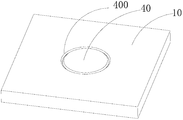
- the specific implementation process is to first plug the liquid injection hole 20 with a T-shaped sealing nail to prevent the electrolyte from overflowing the contaminated weld, and then clean the electrolyte remaining on the surface of the welding area. Finally, the sealing portion 40 and the welding portion 400 of the liquid injection hole 20 are sealed by laser full welding, and the welding is completed to form a full welding seam.
- the mechanism of crack generation the thermal effect of welding leads to the internal stress of welding in the weld. During the full welding process, when the weld contains more low-melting impurities, the impurities are easily concentrated in the center of the weld to form a liquid film. The weld will crack and form cracks under the action of large tensile stress.
- the present application provides a liquid injection hole welding assembly for a secondary battery, which can effectively prevent the occurrence of weld cracks.
- the present application provides a liquid injection hole welding assembly for a secondary battery, comprising a housing top cover, a liquid injection hole, a sealing cover plate, and a stress relief structure, wherein the liquid injection hole is opened on the housing top cover, and Arranging a mounting platform and a through hole from the top end to the bottom end of the top cover of the housing, the dense a sealing cover is received in the assembly sinking platform and does not fall into the through hole, and an upper edge of the sealing cover plate and an upper edge of the assembly sinking table form a welding portion for welding,
- the stress relief structure is disposed on one or both sides of the welded portion and is capable of releasing stress from the welded portion.
- the stress relief structure includes a first stress relief groove disposed on the sealing cover, the first stress relief groove being annularly distributed along an edge of the sealing cover.
- the stress relief structure includes a second stress relief groove disposed on the top cover of the housing, the second stress relief groove being annularly distributed along an edge of the assembly sink.
- the first stress relief groove and/or the second stress relief groove have a shortest distance from the welded portion of 0.1 to 1 mm.
- the first stress relief groove and/or the second stress relief groove have a rectangular, trapezoidal, circular arc or triangular cross section.
- the first stress relief groove and/or the second stress relief groove have a depth of 0.1-5.5 mm.
- the stress relief structure includes an annular boss disposed on the top cover of the housing, the mounting platform being surrounded by the annular boss.
- the annular boss has a top end thickness of 0.1 to 1 mm.
- the annular boss has a height of 0.1 to 5.5 mm.
- an angle between an outer side surface of the annular boss and the top cover of the housing is a right angle or an obtuse angle.
- the bottom of the sealing cover is provided with a escaping chamber recessed toward the inside of the sealing cover, the escaping chamber being in the surrounding range of the first stress relief groove, passing between the two Block.
- the wall thickness of the partition wall is smaller than the wall thickness between the escape chamber and the upper surface of the sealing cover.
- the partition wall is provided in an inclined manner.
- the partition wall is inclined downward from the bottom to the middle of the sealing cover.
- the first stress relief groove and/or the escape chamber and the partition wall are rounded transitions.
- the liquid injection hole welding assembly of the secondary battery provided by the present application passes through the sealing cover and the loading A stress relief structure is arranged near the welding site of the countersink. When the welded portion is fully welded, the stress relief structure can effectively release the stress near the weld and prevent the weld from cracking.
- FIG. 1 is a schematic structural view of a secondary battery provided by the background art of the present application.
- FIG. 2 is a schematic view showing the assembly structure of a liquid injection hole welding assembly of a secondary battery provided by the background art of the present application;
- FIG. 3 is a schematic exploded view of a liquid injection hole welding assembly of a secondary battery with a first stress relief groove according to an embodiment of the present application
- FIG. 4 is a schematic structural view of a liquid injection hole welding assembly of a secondary battery with a first stress relief groove according to an embodiment of the present application
- FIG. 5 is a schematic exploded view of a liquid injection hole welding assembly of a secondary battery with a second stress relief groove according to an embodiment of the present application
- FIG. 6 is a schematic structural view of a liquid injection hole welding assembly of a secondary battery with a second stress relief groove according to an embodiment of the present application
- FIG. 7 is a schematic exploded view showing a liquid injection hole welding assembly of a secondary battery with an annular boss according to an embodiment of the present application
- FIG. 8 is a schematic structural view of a liquid injection hole welding assembly of a secondary battery with an annular boss according to an embodiment of the present application
- FIG. 9 is a schematic exploded view of a liquid injection hole welding assembly of a secondary battery with a first stress relief groove and a second stress relief groove according to an embodiment of the present application;
- FIG. 10 is a schematic structural view of a liquid injection hole welding assembly of a secondary battery with a first stress relief groove and a second stress relief groove according to an embodiment of the present application;
- FIG. 11 is a schematic exploded view of a liquid injection hole welding assembly of a secondary battery with a first stress relief groove and an annular boss provided by an embodiment of the present application;
- FIG. 12 is a schematic structural view of a liquid injection hole welding assembly of a secondary battery with a first stress relief groove and an annular boss provided by an embodiment of the present application;
- FIG. 13 is a liquid injection hole welding of a secondary battery disposed in a partition wall according to an embodiment of the present application; Schematic diagram of the exploded structure of the assembly;
- FIG. 14 is a schematic diagram showing the combined structure of a liquid injection hole welding assembly of a secondary battery provided with a partition wall inwardly provided according to an embodiment of the present application.
- 200-assembly sinking table 200a-side; 200b-bottom; 202-through hole;
- 500-first stress relief groove 502-second stress relief groove; 504-annular boss; 504a-outer side.
- the embodiment of the present application provides a liquid injection hole welding assembly for a secondary battery, including a housing top cover 10, a liquid injection hole 20, a sealing nail 30, a sealing cover 40, and a stress relief structure. 50.
- the housing top cover 10 and the sealing cover 40 may be made of a metal material such as aluminum, aluminum alloy, stainless steel or iron, and the liquid injection hole 20 is opened on the housing top cover 10, and is shelled along the thickness direction of the housing top cover 10.
- the top end of the top cover 10 is bottom end, and the liquid injection hole 20 sequentially includes an assembly sink 200 and a through hole 202. There is a stepwise transition between the assembly sink 200 and the through hole 202.
- the radial dimension of the assembly sink 200 is greater than the radial dimension of the through hole 202.
- the size of the through hole 202 is matched with the size of the sealing nail 30.
- the sealing nail 30 can be made of rubber or silicone material. When the sealing nail 30 is inserted into the through hole 202, the sealing of the through hole 202 can be achieved.
- the sealing of the through hole 202 can also be performed by adhering the diaphragm to the bottom surface 200b of the assembly table 200.
- the material of the diaphragm can be plastic, metal or plastic-metal composite.
- the mounting table 200 is for receiving the sealing cover 40, and the upper edge thereof and the upper edge of the sealing cover 40 form a welding portion 400 for welding, and the welding portion 400 is generally an annulus having a width of 0-0.3 mm.
- the sealing cover 40 and the housing top cover 10 can be sealed by full soldering along the welded portion 400.
- the stress relief structure 50 is disposed on the inner side or the outer side of the welded portion 400, and functions to release the welding stress from the welded portion 400.
- the stress relief structure 50 is described in detail below.
- the stress relief structure 50 may be disposed only on the inner side of the welded portion 400 (see FIGS. 3 and 4), that is, the first stress relief groove 500 disposed on the sealing cover 40.
- the first stress relief grooves 500 are annularly distributed along the edges of the sealing cover 40. It may be a complete annular structure or may be composed of several segments distributed in a ring shape.
- a escaping chamber 402 recessed toward the inside of the sealing cover 40 may be disposed at the bottom of the sealing cover, and the escaping chamber 402 can be sealed.
- the top of the nail 30 is evaded to avoid contact interference between the two.
- the avoidance chamber 402 is within the surrounding range of the first strain relief groove 500, and is blocked by the partition wall 404 therebetween.
- the stress release effect can be further improved by the following two methods.
- the first type is that the wall thickness of the partition wall 404 is designed to be smaller than the wall thickness between the escape chamber 402 and the upper surface of the sealing cover 40, so that the partition wall 404 is more susceptible to deformation, thereby releasing stress.
- the second type is that the partition wall 404 is inclined, so that the horizontal direction stress can be converted into the vertical direction by the partition wall 404, so that the thickness of the sealing cover 40 is changed to cancel the stress.
- the partition wall 404 is preferably inverted from the bottom to the middle of the sealing cover 40 so that the first stress relief groove 500 and the escape chamber 402 both form an open structure, which is more advantageous for stress release.
- the first stress relief groove 500 and the escape chamber 402 and the partition wall 404 may be rounded. The corners are transitioned (see Figures 13 and 14).
- the above structure can better release the inner side of the welded portion 400, that is, the stress on the sealing cover 40, but this structure cannot release the welding stress on the outer side of the welded portion 400.
- the stress relief structure 50 may also be disposed only on the outer side of the welded portion 400, that is, on the casing top cover 10.
- the first structure is similar to the first stress relief groove 500 in that a second stress relief groove 502 is provided on the housing cover 10 in an annular shape along the edge of the assembly stage 200 (see Figs. 5 and 6).
- the second strain relief groove 502 is annularly distributed along the edge of the assembly sink 200.
- the second stress relief groove 502 may also be composed of a complete annular structure or a plurality of segments distributed in a ring shape.
- the second structure is such that an annular boss 504 is disposed on the housing top cover 10 above the surface of the housing top cover 10.
- the assembly sunken table 200 is disposed in the annular boss 504 and is surrounded by the annular boss 504. Surrounded (see Figures 7 and 8). Both of these configurations provide sufficient cushioning of the outside of the weld to provide a good release of the weld stress on the outside, but in contrast, the weld stress on the inside cannot be released.
- the stress relief structure 50 is disposed on the housing top cover 10
- the electrolyte is often sandwiched between the second stress relief groove 502 or the annular boss 504 and the housing top cover 10. Accumulation in the corners, therefore, in the use of these two structures, a strict cleaning procedure is required before welding, and the accumulated electrolyte is cleaned using dimethyl carbonate (DMC).
- DMC dimethyl carbonate
- the angle between the outer side surface 504a of the annular boss 504 and the housing top cover 10 can be set to a right angle or an obtuse angle. The larger the angle, the less likely it is to accumulate electrolyte, making the cleaning process easier.
- the first stress relief groove 500 is selected to be matched with the second stress relief groove 502 (see FIGS. 9 and 10), or the first stress relief groove 500 is selected to be matched with the annular boss 504 (see FIGS. 11 and 12). ) can be.
- first stress relief groove 500 and the second stress relief groove 502 it is preferable to maintain a shortest distance of 0.1 to 1 mm from the welded portion 400. The farther the distance is, the smaller the release effect on stress is.
- the cross-sectional shape of the first stress relief groove 500 and the second stress relief groove 502 may be rectangular, trapezoidal, circular arc, or triangular, etc., depending on the type and size of the secondary battery, the housing cover 10, and the sealing cover 40.
- the thickness of the housing top cover 10 is 0.6-6 mm
- the depth of the first stress relief groove 500 and the second stress relief groove 502 is preferably selected within the range of 0.1-5.5 mm. If the depth is too large to affect the structural strength of the housing top cover 10 and the sealing cover 40, the depth is too small to reduce the stress release capability.
- the minimum thickness is also kept in the range of 0.1-1 mm.
- the larger the thickness the smaller the effect of releasing the stress, but the thickness is too small, which easily causes the annular boss 504 to be damaged due to the low strength.
- the height of the annular boss 504 can be maintained at 0.1-5.5 mm. If the height is too large, the manufacturing cost of the annular boss 504 is increased, and if the height is too small, the stress releasing ability is lowered.
- the sealing nail 30 and the sealing cover 40 may be fixed together, which can reduce the step of separately inserting the sealing nail 30 into the liquid filling hole 20.
Landscapes
- Chemical & Material Sciences (AREA)
- Chemical Kinetics & Catalysis (AREA)
- Electrochemistry (AREA)
- General Chemical & Material Sciences (AREA)
- Engineering & Computer Science (AREA)
- Inorganic Chemistry (AREA)
- Materials Engineering (AREA)
- Manufacturing & Machinery (AREA)
- Filling, Topping-Up Batteries (AREA)
- Sealing Battery Cases Or Jackets (AREA)
Abstract
本申请涉及储能器件领域,尤其涉及一种二次电池的注液孔焊接组件,包括壳体顶盖、注液孔、密封盖板以及应力释放结构,注液孔开设于壳体顶盖上,且沿壳体顶盖的厚度方向依次包括装配沉台以及通孔,装配沉台与通孔之间呈阶梯状过渡,且装配沉台的径向尺寸大于通孔的径向尺寸,密封盖板收容于装配沉台,所述应力释放结构设置在所述焊接部位的一侧或两侧,且能够释放来自所述焊接部位的应力。本申请所提供的二次电池的注液孔焊接组件通过在密封盖板以及装配沉台的焊接部位附近设置应力释放结构,当焊接部位进行满焊焊接后,应力释放结构能够有效释放焊缝附近的应力,防止焊缝产生裂纹。
Description
本申请涉及储能器件领域,尤其涉及一种二次电池的注液孔焊接组件。
在二次电池(例如锂离子电池)的制造过程中,在完成注液工序之后,需要将壳体顶盖上的注液孔进行激光密封焊接,以防止电解液的泄漏。
相关技术中,如图1和2所示,具体实施过程是先用T型密封钉塞住注液孔20,防止电解液溢出污染焊缝,之后对残留在焊接区域表面的电解液进行清洁,最后将密封盖板40和注液孔20的焊接部位400用激光满焊的方式来密封,焊接完形成满焊焊缝。
焊接过程中由于冷热收缩会产生应力,焊接应力得不到释放会残留在焊缝中,且焊缝属于平面环状焊缝,焊接应力集中现象更加明显,当焊接应力达到一定程度就会造成焊缝开裂,产生焊接裂纹。目前满焊焊缝因焊接应力导致的裂纹至今未彻底解决,尤其微小的裂纹不易检出,很容易造成漏液,存在非常大的安全隐患。
裂纹产生的机理:焊接的热效应导致焊缝内产生焊接内应力,满焊过程中,当焊缝含有较多的低熔点杂质时,杂质容易富集在焊缝中心位置,形成液态薄膜,在较大的拉伸应力作用下焊缝会开裂,形成裂纹。
实用新型内容
本申请提供了一种二次电池的注液孔焊接组件,能够有效防止焊接裂纹的发生。
本申请提供了一种二次电池的注液孔焊接组件,包括壳体顶盖、注液孔、密封盖板以及应力释放结构,所述注液孔开设于所述壳体顶盖上,且从所述壳体顶盖的顶端到底端的方向依次包括装配沉台以及通孔,所述密
封盖板收容于所述装配沉台内且不会落入所述通孔中,并且所述密封盖板的上边缘与所述装配沉台的上边缘形成用于进行焊接的焊接部位,所述应力释放结构设置在所述焊接部位的一侧或两侧,且能够释放来自所述焊接部位的应力。
优选地,所述应力释放结构包括设置在所述密封盖板上的第一应力释放槽,所述第一应力释放槽沿所述密封盖板的边缘成环状分布。
优选地,所述应力释放结构包括设置在所述壳体顶盖上的第二应力释放槽,所述第二应力释放槽沿所述装配沉台的边缘成环状分布。
优选地,所述第一应力释放槽和/或所述第二应力释放槽距所述焊接部位的最短距离为0.1-1mm。
优选地,所述第一应力释放槽和/或所述第二应力释放槽的截面为矩形、梯形、圆弧形或三角形。
优选地,所述第一应力释放槽和/或所述第二应力释放槽的深度为0.1-5.5mm。
优选地,所述应力释放结构包括设置在所述壳体顶盖上的环状凸台,所述装配沉台设被所述环状凸台包围。
优选地,所述环状凸台的顶端厚度为0.1-1mm。
优选地,所述环状凸台的高度为0.1-5.5mm。
优选地,所述环状凸台的外侧面与所述壳体顶盖之间的夹角为直角或钝角。优选地,所述密封盖板的底部设置有向所述密封盖板的内部凹陷的避让腔室,所述避让腔室处于所述第一应力释放槽的环绕范围内,二者之间通过隔壁进行阻隔。
优选地,所述隔壁的壁厚小于所述避让腔室与所述密封盖板的上表面之间的壁厚。
优选地,所述隔壁为倾斜设置。
优选地,所述隔壁由下至上向所述密封盖板的中部内倾。
优选地,所述第一应力释放槽和/或所述避让腔室与所述隔壁均为圆角过渡。
本申请提供的技术方案可以达到以下有益效果:
本申请所提供的二次电池的注液孔焊接组件通过在密封盖板以及装
配沉台的焊接部位附近设置应力释放结构,当焊接部位进行满焊焊接后,应力释放结构能够有效释放焊缝附近的应力,防止焊缝产生裂纹。
应当理解的是,以上的一般描述和后文的细节描述仅是示例性的,并不能限制本申请。
图1为本申请背景技术所提供的二次电池的整体结构意图;
图2为本申请背景技术所提供的二次电池的注液孔焊接组件的装配结构示意图;
图3为本申请实施例所提供的带有第一应力释放槽的二次电池的注液孔焊接组件的分解结构示意图;
图4为本申请实施例所提供的带有第一应力释放槽的二次电池的注液孔焊接组件的组合结构示意图;
图5为本申请实施例所提供的带有第二应力释放槽的二次电池的注液孔焊接组件的分解结构示意图;
图6为本申请实施例所提供的带有第二应力释放槽的二次电池的注液孔焊接组件的组合结构示意图;
图7为本申请实施例所提供的带有环状凸台的二次电池的注液孔焊接组件的分解结构示意图;
图8为本申请实施例所提供的带有环状凸台的二次电池的注液孔焊接组件的组合结构示意图;
图9为本申请实施例所提供的同时带有第一应力释放槽以及第二应力释放槽的二次电池的注液孔焊接组件的分解结构示意图;
图10为本申请实施例所提供的同时带有第一应力释放槽以及第二应力释放槽的二次电池的注液孔焊接组件的组合结构示意图;
图11为本申请实施例所提供的同时带有第一应力释放槽以及环状凸台的二次电池的注液孔焊接组件的分解结构示意图;
图12为本申请实施例所提供的同时带有第一应力释放槽以及环状凸台的二次电池的注液孔焊接组件的组合结构示意图;
图13为本申请实施例所提供的隔壁内倾设置的二次电池的注液孔焊
接组件的分解结构示意图;
图14为本申请实施例所提供的隔壁内倾设置的二次电池的注液孔焊接组件的组合结构示意图。
附图标记:
10-壳体顶盖;
20-注液孔;
200-装配沉台;200a-侧面;200b-底面;202-通孔;
30-密封钉;
40-密封盖板;
400-焊接部位;
402-避让腔室;
404-隔壁;
50-应力释放结构;
500-第一应力释放槽;502-第二应力释放槽;504-环状凸台;504a-外侧面。
此处的附图被并入说明书中并构成本说明书的一部分,示出了符合本申请的实施例,并与说明书一起用于解释本申请的原理。
下面通过具体的实施例并结合附图对本申请做进一步的详细描述。文中所述“前”、“后”、“左”、“右”、“上”、“下”均以附图中的二次电池的注液孔焊接组件的放置状态为参照。
如图3至12所示,本申请实施例提供了一种二次电池的注液孔焊接组件,包括壳体顶盖10、注液孔20、密封钉30、密封盖板40以及应力释放结构50。
壳体顶盖10以及密封盖板40可由铝、铝合金、不锈钢或铁等金属材料制成,注液孔20开设于壳体顶盖10上,沿着壳体顶盖10的厚度方向由壳体顶盖10的顶端到底端,注液孔20依次包括装配沉台200以及通孔202。装配沉台200与通孔202之间呈阶梯状过渡。装配沉台200的径向尺寸大于通孔202的径向尺寸。
通孔202的尺寸与密封钉30的尺寸相配合,密封钉30可采用橡胶或硅胶材质,当密封钉30塞入通孔202时,便可实现对通孔202的密封。对通孔202的密封方式还可以采用将膜片胶粘于装配沉台200的底面200b上,膜片的材质可以为塑料、金属或塑料-金属复合材料。装配沉台200用于收容密封盖板40,并且其上边缘与密封盖板40的上边缘形成用于焊接的焊接部位400,该焊接部位400一般为一道宽度为0-0.3mm的环隙,通过沿该焊接部位400进行满焊焊接的方式可使密封盖板40与壳体顶盖10实现密封。
应力释放结构50设置在焊接部位400的内侧或者外侧,其作用是能够释放来自焊接部位400的焊接应力。下面针对应力释放结构50进行详细描述。
在本申请实施例中,应力释放结构50可以为仅设置在焊接部位400的内侧(参见图3和4),也就是设置在密封盖板40上的第一应力释放槽500。第一应力释放槽500沿密封盖板40的边缘成环状分布。其可以为一个完整的环状结构,也可以分别由呈环状分布的几段共同组成。在完成电解液注入后,对装配沉台200内部以及周边进行简单清洗,便可加盖密封盖板40并进行焊接。当焊接完成后,由于第一应力释放槽500在焊缝的内侧,因此可以对内侧的焊接应力进行释放。
在本实施例中,为了防止密封盖板40与密封钉30发生干涉,可以在密封盖板的底部设置一个向密封盖板40的内部凹陷的避让腔室402,该避让腔室402能够对密封钉30的顶部进行避让,从而避免二者发生触碰干涉。避让腔室402处于第一应力释放槽500的环绕范围内,二者之间则通过隔壁404进行阻隔。
此时,可以通过下列两种方式进一步提高应力释放效果。第一种是将隔壁404的壁厚设计的小于避让腔室402与密封盖板40的上表面之间的壁厚,从而使隔壁404更加容易发生形变,从而释放应力。第二种则是将隔壁404倾斜设置,这样能够利用隔壁404将水平方向上的应力转换为竖直方向的作用力,从而使密封盖板40的厚度发生变化,来抵消应力。此时,隔壁404最好由下至上向密封盖板40的中部内倾,以使第一应力释放槽500以及避让腔室402均形成敞口结构,更加利于应力的释放。并且,
为了防止因形变而导致第一应力释放槽500或者避让腔室402在隔壁404处因角度变化过大而发生撕裂,可以将第一应力释放槽500以及避让腔室402与隔壁404均采用圆角进行过渡(参见图13和图14)。
上述结构能够较好的释放焊接部位400的内侧,也就是密封盖板40上的应力,但这种结构却无法释放焊接部位400外侧的焊接应力。
此外,在本实施例中,应力释放结构50也可以仅设置在焊接部位400的外侧,也就是壳体顶盖10上。此时可以有两种结构。第一种结构与第一应力释放槽500类似,在壳体顶盖10上设置沿着装配沉台200的边缘呈环状分布的第二应力释放槽502(参见图5和6)。第二应力释放槽502沿着装配沉台200的边缘呈环状分布。与第一应力释放槽500类似,第二应力释放槽502也可以由一个完整的环状结构或者呈环状分布的几段共同组成。第二种结构为在壳体顶盖10上设置一个高于壳体顶盖10的表面的环状凸台504,装配沉台200设置在环状凸台504内,并被环状凸台504所包围(参见图7和8)。这两种结构均可使焊缝的外侧获得足够的缓冲,能够对外侧的焊接应力进行很好的释放,但与之相对的,无法释放内侧的焊接应力。并且,这两种结构中,由于应力释放结构50设置在壳体顶盖10上,因此电解液经常会在第二应力释放槽502或者环状凸台504与壳体顶盖10之间的夹角内积存,因此,在采用这两种结构时,在焊接前还需要增加一道严格的清洗程序,采用碳酸二甲酯(DMC)对积存的电解液进行清理。
当采用第二种结构时,可以将环状凸台504的外侧面504a与壳体顶盖10之间的夹角设置为直角或钝角。角度越大则越不容易积存电解液,使清洗过程变得更为容易。
前面的几种结构由于只能够对单侧的焊接应力进行释放,因此在焊接时还是需要激光器采用大脉宽参数以减少焊接应力,因此焊接成本较高,焊接应力改善效果不显著。为了提高应力的释放能力,最好同时在焊缝的两侧,也就是在壳体顶盖10以及密封盖板40上均设置应力释放结构50。具体配合时,选择第一应力释放槽500与第二应力释放槽502进行搭配(参见图9和10),或者选择第一应力释放槽500与环状凸台504进行搭配(参见图11和12)均可。
对于第一应力释放槽500以及第二应力释放槽502,二者最好与焊接部位400之间保持0.1-1mm的最短间距,距离越远对于应力的释放效果越小。第一应力释放槽500和第二应力释放槽502的截面形状为矩形、梯形、圆弧形或三角形等形状均可,根据二次电池的型号、尺寸、壳体顶盖10以及密封盖板40的厚度等差异,对于一般情况,壳体顶盖10的厚度为0.6-6mm,第一应力释放槽500以及第二应力释放槽502的深度最好在0.1-5.5mm范围内合理选择。如果深度过大会影响壳体顶盖10以及密封盖板40的结构强度,深度过小则会降低应力释放能力。
而对于环状凸台504,其最小厚度也要保持在0.1-1mm范围内,厚度越大对于应力的释放效果越小,但厚度过小则很容易导致环状凸台504因强度过低损坏。环状凸台504的高度可以保持在0.1-5.5mm,如果高度过大会增加环状凸台504的制造成本,高度过小则会降低应力释放能力。
为了提高密封盖板40与装配沉台200之间的配合精度,同时降低装配难度,最好将装配沉台200的侧面200a与底面200b之间的夹角保持在直角或钝角范围内,并且,角度越大越易于装配。
在本实施例中,为了进一步简化焊接封装工艺,可以将密封钉30与密封盖板40固定在一起,这样能够减少单独将密封钉30塞入注液孔20的步骤。
以上所述仅为本申请的优选实施例而已,并不用于限制本申请,对于本领域的技术人员来说,本申请可以有各种更改和变化。凡在本申请的精神和原则之内,所作的任何修改、等同替换、改进等,均应包含在本申请的保护范围之内。
Claims (15)
- 一种二次电池的注液孔焊接组件,其特征在于,包括壳体顶盖、注液孔、密封盖板以及应力释放结构,所述注液孔开设于所述壳体顶盖上,且从所述壳体顶盖的顶端到底端的方向依次包括装配沉台以及通孔,所述密封盖板收容于所述装配沉台内且不会落入所述通孔中,并且所述密封盖板的上边缘与所述装配沉台的上边缘形成用于进行焊接的焊接部位,所述应力释放结构设置在所述焊接部位的一侧或两侧,其能够释放来自所述焊接部位的应力。
- 根据权利要求1所述的二次电池的注液孔焊接组件,其特征在于,所述应力释放结构包括设置在所述密封盖板上的第一应力释放槽,所述第一应力释放槽沿所述密封盖板的边缘成环状分布。
- 根据权利要求2所述的二次电池的注液孔焊接组件,其特征在于,所述应力释放结构包括设置在所述壳体顶盖上的第二应力释放槽,所述第二应力释放槽沿所述装配沉台的边缘成环状分布。
- 根据权利要求3所述的二次电池的注液孔焊接组件,其特征在于,所述第一应力释放槽和/或所述第二应力释放槽距所述焊接部位的最短距离为0.1-1mm。
- 根据权利要求3所述的二次电池的注液孔焊接组件,其特征在于,所述第一应力释放槽和/或所述第二应力释放槽的截面为矩形、梯形、圆弧形或三角形。
- 根据权利要求3所述的二次电池的注液孔焊接组件,其特征在于,所述第一应力释放槽和/或所述第二应力释放槽的深度为0.1-5.5mm。
- 根据权利要求1或2所述的二次电池的注液孔焊接组件,其特征在于,所述应力释放结构包括设置在所述壳体顶盖上的环状凸台,所述装配沉台被所述环状凸台包围。
- 根据权利要求7所述的二次电池的注液孔焊接组件,其特征在于,所述环状凸台的最小厚度为0.1-1mm。
- 根据权利要求7所述的二次电池的注液孔焊接组件,其特征在于,所述环状凸台的高度为0.1-5.5mm。
- 根据权利要求7所述的二次电池的注液孔焊接组件,其特征在于,所述环状凸台的外侧面与所述壳体顶盖之间的夹角为直角或钝角。
- 根据权利要求2所述的二次电池的注液孔焊接组件,其特征在于,所述密封盖板的底部设置有向所述密封盖板的内部凹陷的避让腔室,所述避让腔室处于所述第一应力释放槽的环绕范围内,二者之间通过隔壁进行阻隔。
- 根据权利要求11所述的二次电池的注液孔焊接组件,其特征在于,所述隔壁的壁厚小于所述避让腔室与所述密封盖板的上表面之间的壁厚。
- 根据权利要求11或12所述的二次电池的注液孔焊接组件,其特征在于,所述隔壁为倾斜设置。
- 根据权利要求13所述的二次电池的注液孔焊接组件,其特征在于,所述隔壁由下至上向所述密封盖板的中部内倾。
- 根据权利要求14所述的二次电池的注液孔焊接组件,其特征在于,所述第一应力释放槽和/或所述避让腔室与所述隔壁均为圆角过渡。
Priority Applications (1)
| Application Number | Priority Date | Filing Date | Title |
|---|---|---|---|
| US15/868,968 US10581058B2 (en) | 2015-07-15 | 2018-01-11 | Welding assembly for liquid-injection hole of secondary battery |
Applications Claiming Priority (2)
| Application Number | Priority Date | Filing Date | Title |
|---|---|---|---|
| CN201520510595.5U CN204809306U (zh) | 2015-07-15 | 2015-07-15 | 二次电池的注液孔焊接组件 |
| CN201520510595.5 | 2015-07-15 |
Related Child Applications (1)
| Application Number | Title | Priority Date | Filing Date |
|---|---|---|---|
| US15/868,968 Continuation US10581058B2 (en) | 2015-07-15 | 2018-01-11 | Welding assembly for liquid-injection hole of secondary battery |
Publications (1)
| Publication Number | Publication Date |
|---|---|
| WO2017008577A1 true WO2017008577A1 (zh) | 2017-01-19 |
Family
ID=54594081
Family Applications (1)
| Application Number | Title | Priority Date | Filing Date |
|---|---|---|---|
| PCT/CN2016/082995 Ceased WO2017008577A1 (zh) | 2015-07-15 | 2016-05-23 | 二次电池的注液孔焊接组件 |
Country Status (3)
| Country | Link |
|---|---|
| US (1) | US10581058B2 (zh) |
| CN (1) | CN204809306U (zh) |
| WO (1) | WO2017008577A1 (zh) |
Cited By (1)
| Publication number | Priority date | Publication date | Assignee | Title |
|---|---|---|---|---|
| WO2022206950A1 (zh) * | 2021-04-02 | 2022-10-06 | 广东微电新能源有限公司 | 电池盖板以及电池 |
Families Citing this family (28)
| Publication number | Priority date | Publication date | Assignee | Title |
|---|---|---|---|---|
| CN204809306U (zh) | 2015-07-15 | 2015-11-25 | 宁德时代新能源科技有限公司 | 二次电池的注液孔焊接组件 |
| CN106876620B (zh) * | 2015-12-14 | 2023-08-22 | 宁德时代新能源科技股份有限公司 | 二次电池注液孔密封组件 |
| CN107359304B (zh) * | 2016-05-10 | 2020-08-28 | 宁德时代新能源科技股份有限公司 | 锂离子电池注液孔密封结构 |
| CN107199393A (zh) * | 2017-06-02 | 2017-09-26 | 深圳吉阳智能科技有限公司 | 一种电池注液口密封钉焊接设备 |
| CN107331804A (zh) * | 2017-06-29 | 2017-11-07 | 大族激光科技产业集团股份有限公司 | 一种动力电池、其密封钉及其焊接方法 |
| CN107732042B (zh) * | 2017-09-26 | 2021-02-05 | 惠州市亿纬新能源研究院 | 一种盖帽及包含该盖帽的锂电池 |
| CN107978700A (zh) * | 2017-12-28 | 2018-05-01 | 桑德集团有限公司 | 一种用于电池金属外壳的盖板以及金属外壳 |
| CN112421155A (zh) * | 2019-08-05 | 2021-02-26 | 比亚迪股份有限公司 | 电池及其盖板组件 |
| CN112542664A (zh) * | 2019-09-23 | 2021-03-23 | 湖南弘毅科技有限公司 | 方形锂电池及方形锂电池的气密检测方法 |
| KR102972407B1 (ko) * | 2020-04-29 | 2026-06-01 | 주식회사 엘지에너지솔루션 | 전지 모듈 및 이를 포함하는 전지팩 |
| CN112260020A (zh) * | 2020-10-10 | 2021-01-22 | 桑顿新能源科技有限公司 | 一种汇流排、汇流排组件、软包电池模组以及软包电池 |
| CN112510327B (zh) * | 2020-12-22 | 2022-12-02 | 北京理工大学深圳汽车研究院(电动车辆国家工程实验室深圳研究院) | 一种动力电池及其封口方法 |
| CN115475986B (zh) * | 2021-06-15 | 2023-11-17 | 宁德时代新能源科技股份有限公司 | 清洁设备、电池单体、用电装置及电池单体加工方法 |
| CN216354675U (zh) * | 2021-10-18 | 2022-04-19 | 厦门海辰新能源科技有限公司 | 一种电池顶盖 |
| CN113857670B (zh) * | 2021-10-28 | 2024-02-13 | 广东利元亨智能装备股份有限公司 | 密封钉焊接设备和方法 |
| CN216213983U (zh) * | 2021-11-04 | 2022-04-05 | 宁德时代新能源科技股份有限公司 | 电池盖板组件、电池单体、电池和用电设备 |
| CN217589375U (zh) * | 2021-12-07 | 2022-10-14 | 湖北亿纬动力有限公司 | 一种电池顶盖片及电池 |
| CN114464938B (zh) * | 2022-01-14 | 2023-08-15 | 欣旺达电动汽车电池有限公司 | 电池顶盖及动力电池 |
| CN115401250A (zh) * | 2022-07-18 | 2022-11-29 | 苏州博海创业微系统有限公司 | 一种低应力可重复AlSi管壳气密性封装模块开盖返工方法 |
| CN115302082B (zh) * | 2022-08-02 | 2025-07-11 | 武汉逸飞激光股份有限公司 | 一种密封钉的焊接方法及装置 |
| CN117638433A (zh) * | 2022-08-12 | 2024-03-01 | 华为技术有限公司 | 一种电池的顶盖组件、二次电池及储能模组 |
| WO2024055257A1 (zh) * | 2022-09-15 | 2024-03-21 | 宁德时代新能源科技股份有限公司 | 电池单体、电池及用电装置 |
| CN115663362B (zh) * | 2022-10-27 | 2024-01-23 | 厦门海辰储能科技股份有限公司 | 一种电池盖板和电池 |
| CN116213930B (zh) * | 2023-02-24 | 2024-09-20 | 三一红象电池有限公司 | 一种密封钉辅助焊接设备及密封钉焊接方法 |
| WO2024222849A1 (zh) * | 2023-04-26 | 2024-10-31 | 江苏正力新能电池技术有限公司 | 电池顶盖组件、电池及用电设备 |
| CN116404321B (zh) * | 2023-05-31 | 2024-03-26 | 深圳海辰储能控制技术有限公司 | 下塑胶、端盖组件、储能装置及用电设备 |
| CN117013159B (zh) * | 2023-07-03 | 2025-01-21 | 蜂巢能源科技股份有限公司 | 电池及其装配方法 |
| CN118180429A (zh) * | 2024-04-12 | 2024-06-14 | 中国机械总院集团宁波智能机床研究院有限公司 | 刀具及刀具制备方法 |
Citations (6)
| Publication number | Priority date | Publication date | Assignee | Title |
|---|---|---|---|---|
| JP2006040690A (ja) * | 2004-07-27 | 2006-02-09 | Nec Tokin Tochigi Ltd | 密閉型電池 |
| CN102986062A (zh) * | 2010-07-09 | 2013-03-20 | 日立车辆能源株式会社 | 密闭型电池 |
| CN202905851U (zh) * | 2012-09-17 | 2013-04-24 | 天津力神电池股份有限公司 | 一种电池注液孔的封口结构 |
| CN203659981U (zh) * | 2014-01-21 | 2014-06-18 | 杭州山合江新能源技术有限公司 | 一种带内凹式塞体的注液孔密封结构 |
| CN203830931U (zh) * | 2014-01-24 | 2014-09-17 | 北京雷蒙赛博机电技术有限公司 | “w”形密封连接焊口 |
| CN204809306U (zh) * | 2015-07-15 | 2015-11-25 | 宁德时代新能源科技有限公司 | 二次电池的注液孔焊接组件 |
Family Cites Families (4)
| Publication number | Priority date | Publication date | Assignee | Title |
|---|---|---|---|---|
| KR100684765B1 (ko) * | 2005-05-16 | 2007-02-20 | 삼성에스디아이 주식회사 | 이차 전지 |
| US8227111B2 (en) * | 2006-12-28 | 2012-07-24 | Samsung Sdi Co., Ltd. | Secondary battery having electrolyte sealing plug |
| KR100865404B1 (ko) * | 2007-09-14 | 2008-10-24 | 삼성에스디아이 주식회사 | 이차전지 |
| KR101271254B1 (ko) * | 2010-10-08 | 2013-06-07 | 주식회사 엘지화학 | 전해액 주입구의 밀봉성이 우수한 각형 전지 |
-
2015
- 2015-07-15 CN CN201520510595.5U patent/CN204809306U/zh not_active Expired - Lifetime
-
2016
- 2016-05-23 WO PCT/CN2016/082995 patent/WO2017008577A1/zh not_active Ceased
-
2018
- 2018-01-11 US US15/868,968 patent/US10581058B2/en active Active
Patent Citations (6)
| Publication number | Priority date | Publication date | Assignee | Title |
|---|---|---|---|---|
| JP2006040690A (ja) * | 2004-07-27 | 2006-02-09 | Nec Tokin Tochigi Ltd | 密閉型電池 |
| CN102986062A (zh) * | 2010-07-09 | 2013-03-20 | 日立车辆能源株式会社 | 密闭型电池 |
| CN202905851U (zh) * | 2012-09-17 | 2013-04-24 | 天津力神电池股份有限公司 | 一种电池注液孔的封口结构 |
| CN203659981U (zh) * | 2014-01-21 | 2014-06-18 | 杭州山合江新能源技术有限公司 | 一种带内凹式塞体的注液孔密封结构 |
| CN203830931U (zh) * | 2014-01-24 | 2014-09-17 | 北京雷蒙赛博机电技术有限公司 | “w”形密封连接焊口 |
| CN204809306U (zh) * | 2015-07-15 | 2015-11-25 | 宁德时代新能源科技有限公司 | 二次电池的注液孔焊接组件 |
Cited By (1)
| Publication number | Priority date | Publication date | Assignee | Title |
|---|---|---|---|---|
| WO2022206950A1 (zh) * | 2021-04-02 | 2022-10-06 | 广东微电新能源有限公司 | 电池盖板以及电池 |
Also Published As
| Publication number | Publication date |
|---|---|
| CN204809306U (zh) | 2015-11-25 |
| US10581058B2 (en) | 2020-03-03 |
| US20180138492A1 (en) | 2018-05-17 |
Similar Documents
| Publication | Publication Date | Title |
|---|---|---|
| CN204809306U (zh) | 二次电池的注液孔焊接组件 | |
| CN107359304B (zh) | 锂离子电池注液孔密封结构 | |
| JP6618018B2 (ja) | 円筒型電池 | |
| WO2017087106A3 (en) | Nuclear waste storage canisters | |
| CN205657091U (zh) | 二次电池及其壳体 | |
| CN117691269B (zh) | 一种电芯 | |
| CN112467316B (zh) | 一种注液孔密封结构及动力电池顶盖 | |
| JP5967453B2 (ja) | 密閉型電池、及びその製造方法 | |
| CN206422104U (zh) | 顶盖组件、二次电池及激光焊接系统 | |
| JP6217979B2 (ja) | 密閉型電池の製造方法 | |
| KR20130134948A (ko) | 전해액 주입구 및/또는 가스 배출구를 구비하는 파우치형 전지 | |
| CN208889757U (zh) | 一种电池 | |
| CN102738419B (zh) | 电池端盖组 | |
| JP4622271B2 (ja) | 電池 | |
| CN107104207A (zh) | 二次电池及其顶盖 | |
| CN205543035U (zh) | 二次电池的注液孔焊接组件 | |
| CN104500972B (zh) | 用于深冷压力容器的低温吸附剂装置及其生产工艺 | |
| KR101335052B1 (ko) | 배터리 커버 | |
| CN204464332U (zh) | 便于激光焊接的组合帽 | |
| CN204481060U (zh) | Z结构电池防爆组合盖帽 | |
| JP2015141872A (ja) | 密閉型電池およびその製造方法 | |
| CN203746983U (zh) | 密封型电池 | |
| CN102104118A (zh) | 高容量动力锂电池封口板 | |
| JP2017220393A (ja) | 二次電池 | |
| CN206312999U (zh) | 一种多层动力电池盖防爆安全阀 |
Legal Events
| Date | Code | Title | Description |
|---|---|---|---|
| 121 | Ep: the epo has been informed by wipo that ep was designated in this application |
Ref document number: 16823724 Country of ref document: EP Kind code of ref document: A1 |
|
| NENP | Non-entry into the national phase |
Ref country code: DE |
|
| 122 | Ep: pct application non-entry in european phase |
Ref document number: 16823724 Country of ref document: EP Kind code of ref document: A1 |