WO2017006982A1 - 架橋性樹脂膜及び架橋性樹脂膜の製造方法、太陽電池用封止膜及び太陽電池膜用封止膜の製造方法、基材貼り合せ用中間膜及び基材貼り合せ用中間膜の製造方法、太陽電池モジュール及び太陽電池モジュールの製造方法、積層体及び積層体の製造方法 - Google Patents
架橋性樹脂膜及び架橋性樹脂膜の製造方法、太陽電池用封止膜及び太陽電池膜用封止膜の製造方法、基材貼り合せ用中間膜及び基材貼り合せ用中間膜の製造方法、太陽電池モジュール及び太陽電池モジュールの製造方法、積層体及び積層体の製造方法 Download PDFInfo
- Publication number
- WO2017006982A1 WO2017006982A1 PCT/JP2016/070096 JP2016070096W WO2017006982A1 WO 2017006982 A1 WO2017006982 A1 WO 2017006982A1 JP 2016070096 W JP2016070096 W JP 2016070096W WO 2017006982 A1 WO2017006982 A1 WO 2017006982A1
- Authority
- WO
- WIPO (PCT)
- Prior art keywords
- crosslinkable resin
- resin film
- solar cell
- producing
- film
- Prior art date
- Legal status (The legal status is an assumption and is not a legal conclusion. Google has not performed a legal analysis and makes no representation as to the accuracy of the status listed.)
- Ceased
Links
Images




Classifications
-
- B—PERFORMING OPERATIONS; TRANSPORTING
- B29—WORKING OF PLASTICS; WORKING OF SUBSTANCES IN A PLASTIC STATE IN GENERAL
- B29C—SHAPING OR JOINING OF PLASTICS; SHAPING OF MATERIAL IN A PLASTIC STATE, NOT OTHERWISE PROVIDED FOR; AFTER-TREATMENT OF THE SHAPED PRODUCTS, e.g. REPAIRING
- B29C59/00—Surface shaping of articles, e.g. embossing; Apparatus therefor
- B29C59/02—Surface shaping of articles, e.g. embossing; Apparatus therefor by mechanical means, e.g. pressing
- B29C59/04—Surface shaping of articles, e.g. embossing; Apparatus therefor by mechanical means, e.g. pressing using rollers or endless belts
-
- B—PERFORMING OPERATIONS; TRANSPORTING
- B32—LAYERED PRODUCTS
- B32B—LAYERED PRODUCTS, i.e. PRODUCTS BUILT-UP OF STRATA OF FLAT OR NON-FLAT, e.g. CELLULAR OR HONEYCOMB, FORM
- B32B27/00—Layered products comprising a layer of synthetic resin
- B32B27/32—Layered products comprising a layer of synthetic resin comprising polyolefins
-
- B—PERFORMING OPERATIONS; TRANSPORTING
- B32—LAYERED PRODUCTS
- B32B—LAYERED PRODUCTS, i.e. PRODUCTS BUILT-UP OF STRATA OF FLAT OR NON-FLAT, e.g. CELLULAR OR HONEYCOMB, FORM
- B32B3/00—Layered products comprising a layer with external or internal discontinuities or unevennesses, or a layer of non-planar shape; Layered products comprising a layer having particular features of form
- B32B3/26—Layered products comprising a layer with external or internal discontinuities or unevennesses, or a layer of non-planar shape; Layered products comprising a layer having particular features of form characterised by a particular shape of the outline of the cross-section of a continuous layer; characterised by a layer with cavities or internal voids ; characterised by an apertured layer
- B32B3/30—Layered products comprising a layer with external or internal discontinuities or unevennesses, or a layer of non-planar shape; Layered products comprising a layer having particular features of form characterised by a particular shape of the outline of the cross-section of a continuous layer; characterised by a layer with cavities or internal voids ; characterised by an apertured layer characterised by a layer formed with recesses or projections, e.g. hollows, grooves, protuberances, ribs
Definitions
- the present invention relates to a crosslinkable resin film, and more particularly to a crosslinkable resin film suitable for a solar cell sealing film used in a solar cell module or an intermediate film for bonding substrates.
- a crosslinkable resin film containing an olefin (co) polymer and a crosslinking agent is excellent in transparency, adhesiveness, and the like, so that it is not only a sealing film for solar cells, an intermediate film for bonding substrates such as laminated glass, etc. It is widely used as an adhesive film for bonding an optical filter to a display device.
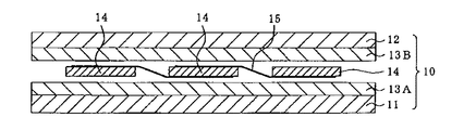
- the solar cell module generally has a surface side transparent protective member 11 made of a glass substrate or the like, a surface side sealing film 13A, a solar cell element 14 such as a silicon crystal cell, and a back side sealing, as shown in FIG.
- the film 13B and the back side protection member (back cover) 12 are laminated in this order, and are manufactured by heat-pressing and cross-linking and curing the surface side sealing film 13A and the back side sealing film 13B.
- the base of the crosslinkable resin film used for these sealing films and the like is not particularly limited.
- olefin (co) polymers are used, and among them, ethylene-vinyl acetate copolymer (EVA) and ethylene-methacrylic acid are used.
- Ethylene-polar monomer copolymers such as acid methyl copolymer (EMMA) and ethylene / ⁇ -olefin copolymers are generally used because of their excellent insulation and sealing properties.
- the type and / or amount of the olefin (co) polymer and other additives as described above can be appropriately changed within a range that does not impair the electrical characteristics of the solar cell, the transparency of the laminated glass, and the like. May vary depending on the structure of the module. Therefore, although the kind of the crosslinkable resin film is appropriately selected and used according to the purpose of use, the crosslinkable resin film is usually transparent or translucent, and the type cannot be identified by its appearance.
- the end of the sealing film (sealing film sheet) is cut into a non-linear shape such as a wave shape or a saw blade shape.
- a non-linear shape such as a wave shape or a saw blade shape.
- Patent Document 1 the sealing film can be identified without being colored (printed).
- the crosslinkable resin film is usually formed into a long shape (tape shape), and then wound up into a roll shape and conveyed / stored.
- the end portion is cut non-linearly. In some cases, the in-line continuous productivity was poor and the yield was poor.
- an object of the present invention is to provide a mark that can be easily identified without damaging the crosslinkable resin film.
- an object of the present invention is to provide a solar cell sealing film, a solar cell module, a base material bonding intermediate film, and a base material bonding method using this crosslinkable resin film.
- the object is to partially heat and melt the processed surface of the crosslinkable resin film containing an olefin (co) polymer and a cross-linking agent and having at least one of the front and back surfaces processed to be uneven.
- the mark portion is formed by the method for producing a crosslinkable resin film.
- the shape of the mark portion emerges from the periphery (the portion where the unevenness remains, the uneven portion) and can be recognized visually. That is, the mark portion can be formed without using a colorant such as ink, and it is not necessary to cut the end portion of the crosslinkable resin film, so that the crosslinkable resin film is hardly damaged.
- Preferred embodiments of the method for producing a crosslinkable resin film of the present invention are as follows.
- a temperature obtained by subtracting 10 ° C. from the melting point of the olefin (co) polymer is defined as a minimum heating temperature, and the processed surface is heated to a temperature equal to or higher than the minimum heating temperature to form the mark portion.
- the mark portion can be reliably flattened in a short time.
- the one minute half-life temperature of the cross-linking agent is set to the maximum heating temperature, and the processed surface is heated to a temperature equal to or lower than the maximum heating temperature to form the mark portion. Thereby, the crosslinking reaction of a crosslinkable resin film can be suppressed.
- the mark portion can be flattened in a short time, and damage other than the mark portion is reduced.
- a carbon dioxide laser is used as the laser.
- the carbon dioxide laser can easily adjust the output and can easily control the temperature of the processed surface.
- the mark is formed by heating the processed surface having an arithmetic average roughness of 1.0 ⁇ m or more and 300 ⁇ m or less of the portion where the unevenness is formed. Thereby, blocking when the crosslinkable resin film is overlapped is effectively suppressed, and the mark portion and the uneven portion can be easily visually distinguished.
- the object includes an olefin (co) polymer and a crosslinking agent, and at least one of the front surface and the back surface is provided with an uneven portion, and a mark portion that is flatter than the uneven portion. It is also achieved by a crosslinkable resin film characterized by having
- the arithmetic average roughness of the uneven portion is 1.0 ⁇ m or more and 300 ⁇ m or less, and the arithmetic average roughness of the mark portion is smaller than the arithmetic average roughness of the uneven portion.
- the object is to produce a solar cell sealing film by the above method, a solar cell module manufacturing method for sealing a solar cell element with the solar cell sealing film, and a solar cell comprising a crosslinkable resin film.
- Sealing film, solar cell module in which a solar cell element is sealed with the sealing film a method for manufacturing an intermediate film for bonding a substrate by the above-described method, and manufacturing a laminate by bonding a substrate with the intermediate film
- the present invention it is possible to form a mark portion without damaging the crosslinkable resin film, and when this crosslinkable resin film is used for a solar cell sealing film or a substrate bonding intermediate film In addition, bonding defects and contamination are unlikely to occur.
- FIG. 1 It is a schematic sectional drawing which shows a general solar cell module.
- the present invention first relates to a method for producing a crosslinkable resin film and a crosslinkable resin film, and the method for producing a crosslinkable resin film mainly comprises: (A) a step of producing a sheet-like crosslinkable resin film having irregularities formed on at least one surface; (B) a step of forming a mark on a surface (processed surface) on which irregularities are formed;
- step (B) Although a commercially available crosslinkable resin film may be used as it is in the step (B), the step (A) may be omitted, or after a commercially available crosslinkable resin film is subjected to unevenness processing, it may be used in the step (B).
- the general process (A) will be described below.
- the step includes a step (a) of forming a crosslinkable resin film into a sheet shape and a step (b) of forming irregularities on the front surface and / or the back surface thereof.
- a sheet-like crosslinkable resin film can be manufactured according to a well-known method.
- a composition containing an olefin (co) polymer and a cross-linking agent can be produced by a method of obtaining a sheet-like material by molding by ordinary extrusion molding or calendar molding (calendering).
- the temperature at the time of molding is a temperature at which the cross-linking agent does not react or hardly reacts, and is preferably below the 1 minute half-life temperature of the cross-linking agent.
- calendar molding since the decomposition of the crosslinking agent may proceed due to a temperature increase in the vicinity of the die, it is preferable to carry out by calendar molding.
- cross-linkable resin film 13 indicates a cross-linkable resin film that is a sheet-like material.
- the surface and the back surface of the crosslinkable resin film 13 are usually smooth.
- step (b) of forming irregularities on the crosslinkable resin film 13 will be described.
- At least one surface is made into the process surface 25 among the surface and the back surface of the crosslinkable resin film 13, and uneven
- the unevenness processing method is not particularly limited, and various methods such as etching, corona discharge, laser irradiation, embossing, etc. can be adopted.
- crosslinking is performed like embossing.
- the method of pressing the concavo-convex mold on the conductive resin film 13 is most preferable.
- embossing is not specifically limited, For example, the crosslinkable resin film 13 is processed by passing between a plurality of rolls (embossing roll, pressure roll).
- Concavities and convexities are formed on the side surface of at least one roll (embossing roll), and the concavity and convexity pattern is formed by pressing the crosslinkable resin film 13 against the concavities and convexities and inverting the concavities and convexities of the roll on the surface of the crosslinkable resin film 13 (Emboss) is formed.
- FIG. 2 (b) shows the crosslinkable resin film 13 in which irregularities are formed on the processed surface 25.
- the concave or convex planar shape is not particularly limited, and may be, for example, a lattice, a mesh, a diamond, a circle (perfect circle or ellipse), a stripe, or a rectangle (square or rectangle).
- the planar shape of the unevenness may be changed in part of the processed surface 25, from the surface of workability, the concaves and / or convexes having substantially the same planar shape are uniformly distributed.
- the arithmetic average roughness Ra (JIS-B0601 (2001)) of the processed surface 25 where the irregularities are formed is preferably 1.0 ⁇ m to 300 ⁇ m, more preferably 1.0 to 100 ⁇ m, and particularly preferably 1.0 to 50 ⁇ m. If this surface roughness (arithmetic average roughness) is too small, blocking is likely to occur when the crosslinkable resin films 13 are overlapped with each other, and if too large, when the mark portion described later is formed, The boundary with the uneven part becomes unclear.
- the film thickness of the crosslinkable resin film 13 is not particularly limited, but the film thickness after the uneven processing is preferably 50 ⁇ m to 2 mm, more preferably 200 ⁇ m to 1.0 mm. If the crosslinkable resin film 13 is too thin, the mechanical strength is weakened, and the heat of the step (B) may damage the deep part of the crosslinkable resin film 13, and if the crosslinkable resin film 13 is too thick, It is not suitable for manufacturing modules that require thinning. Next, the step (B) of forming a mark on the crosslinkable resin film 13 will be described.
- the processing surface 25 is partially heated and a mark is formed.
- the heating method is not particularly limited, and heating methods such as a hot stamp method, a laser irradiation method, and nip processing using a heating roll are used alone or in combination.
- the hot stamp method and the nip processing method are heating methods by heat conduction.
- a plate mold (stamper) in which convex portions are formed is usually used.
- the projection has a planar shape in which a mark to be formed is inverted (mirror character, the planar shape is symmetrical with the shape of the mark).
- the stamper heated by the heating means is moved relative to the crosslinkable resin film 13 and the tip of the convex portion is pressed against the process surface 25 of the crosslinkable resin film 13, so that the process surface 25 is thermally conductive. Heated.
- the laser irradiation method is a method of irradiating the processing surface 25 with laser light 9 having a desired wavelength and heating it (FIG. 2 (c)).
- Laser irradiation is more suitable for the present invention than hot stamping or nip processing because it can be efficiently heated in a short time.
- the type of laser is not particularly limited, and a known laser device can be used, for example, A gas laser using as a medium a gas selected from the group consisting of CO 2 (carbon dioxide), He—Ne, excimer, and argon; A solid-state laser using a solid selected from the group consisting of YAG (yttrium, aluminum, garnet), YVO (yttrium vanadate), Yb (ytterbium) as a medium; A semiconductor laser using a semiconductor selected from the group consisting of AlGaAs / GaAs and GaInAsP / InP as a medium; or -A liquid laser using a liquid in which a pigment is dissolved in a solvent such as alcohol as a medium can be used.
- laser light having a wavelength longer than that of visible light (wavelength of 780 nm or more) is preferable, and a more preferable laser wavelength is 1000 nm or more (1 ⁇ m or more), further preferably 2.0 ⁇ m or more, particularly 10 ⁇ m or more.
- the most preferable laser beam 9 is a carbon dioxide laser having a wavelength exceeding 10 ⁇ m (eg, wavelength 10.6 ⁇ m).
- a long wavelength laser has high heating efficiency of the resin and has low energy (W) as compared with laser light having a short wavelength (eg, less than 780 nm), so that output adjustment is easy and the heating temperature is reduced.
- W energy
- the processing surface 25 is heated to a desired heating temperature by adjusting the output of the laser light 9 applied to the processing surface 25 or by controlling the heating means of the stamper.
- This heating temperature is determined by the olefin (co) polymer used for the crosslinkable resin film 13, preferably, Mp-10 ° C (Mp is the melting point of the olefin (co) polymer. When two or more olefin (co) polymers are used as a mixture, it is the melting point of the mixture. In each case, a differential scanning calorimeter ( DSC))
- DSC differential scanning calorimeter
- the temperature indicated by (minimum heating temperature) is the lower limit.
- the upper limit of the heating temperature is not particularly limited, but the heating is performed at a temperature equal to or lower than the 1 minute half-life temperature (maximum heating temperature) of the crosslinking agent used for the crosslinkable resin film 13.
- the heating temperature is more preferably in the vicinity of the softening point Sp of the olefin (co) polymer, and more preferably, Sp-20 ° C is the lower limit and Sp + 20 ° C is the upper limit.
- the softening point is the Vicat softening point measured by JIS K 7206, and when the olefin (co) polymer is a mixture of two or more resins, it means the softening point of the mixture.
- the processing surface 25 Before the processing surface 25 is heated at the heating temperature as described above, only the surface layer portion (uneven portion) of the crosslinkable resin film 13 is melted, and before the thermal decomposition of the crosslinking agent starts in the lower layer portion (before the crosslinking reaction starts). The heating is finished, and the crosslinkable resin film 13 is cooled if necessary.
- the laser light 9 When heating by the laser irradiation method, the laser light 9 is partially reflected and scattered by the unevenness, so that only the surface layer portion can be melted in a short time.
- the mark portion 18 is distinguished from the concavo-convex portion 16 by this color difference, and the planar shape (contour) of the mark portion 18 can be visually recognized.
- the mark portion 18 is usually composed of one or more patterns (including letters, numbers, figures and symbols), and these patterns are singly or combined to provide one or more pieces of information (model number, material, quality, dimensions, company name, Date, bar code, QR code (registered trademark), etc.). That is, by observing the shape of the mark part 18, unique information given to the crosslinkable resin film 13 can be acquired.
- crosslinkable resin film 13 of the present invention removes only the irregularities (surface layer) to form the mark portion 18, the film thickness distribution is uniform, the roll winding tension does not vary, and wrinkles and tears occur. It is hard to be damaged.
- the uneven portion 16 remains on the processed surface 25 of the crosslinkable resin film 13, and preferably the area of the uneven portion 16 is 50% or more of the total area of the processed surface 25 (one surface of the crosslinkable resin film 13). Is 75% or more, more preferably 90% or more, and particularly 95% or more. If the area of the concavo-convex portion 16 is within this range, blocking is prevented even when the crosslinkable resin films 13 are in close contact with each other as in the roll 2, and the crosslinkable resin film 13 can be smoothly drawn out from the roll 2. Next, the process of manufacturing a solar cell module using this crosslinkable resin film will be described.
- the structure of the solar cell module of the present invention is not particularly limited as long as it includes a structure in which the crosslinkable resin film 13 of the present invention is used as a sealing film and a solar cell element is sealed.
- the structure etc. which sealed the cell for solar cells by carrying out the crosslinking integration by interposing the crosslinkable resin film 13 of this invention between the surface side transparent protection member and the back surface side protection member, etc. are mentioned.
- the side (light-receiving surface side) where the light of the solar cell is irradiated is referred to as “front surface side”, and the side opposite to the light-receiving surface of the solar cell is referred to as “back surface side”.
- the crosslinkable resin film 13 is the roll 2
- the crosslinkable resin film 13 is pulled out from the roll 2 and cut into a predetermined size for use.
- the crosslinkable resin film 13 of the present invention is used as the front surface side sealing film 13A and the back surface side sealing film 13B.
- a resin film 13 may be used.
- the surface side transparent protective member 11, the surface side sealing film 13A, the solar cell element 14 such as a single crystal or polycrystalline silicon cell, the back side sealing film 13B and the back side protective member 12 of the present invention are provided.
- the sealing films 13A and 13B are laminated and cured by a conventional laminating method.
- the laminating method is preferably a heat and pressure method.
- the sealing films 13A and 13B are softened by heating, and the processed surface 25 softened by pressurization is pressed by an object (the other sealing films 13A and 13B or the protective members 11 and 12 etc.), and the concavo-convex part 16 is a mark part. It is flattened to be substantially flush with 18. As a result, in the solar cell module, the mark portion 18 and the concavo-convex portion 16 become indistinguishable, and the unique information of the sealing films 13A and 13B disappears in the finished product.
- the solar cell element 14 is not sufficiently sealed, resulting in a bonding defect. Since the sealing films 13A and 13B of the present invention finish the heating before the crosslinking reaction proceeds in the uneven lower layer portion when forming the mark portion 18, the sealing films 13A and 13B are uncrosslinked. Therefore, when the crosslinkable resin film 13 of the present invention is used, no bonding defect occurs. Moreover, since no colorant such as a pigment is used in the mark portion 18, the solar cell element 14 is not contaminated.
- crosslinkable resin film 13 of the present invention uses the crosslinkable resin film 13 of the present invention as a solar cell sealing film, but the present invention is not limited to this, and the crosslinkable resin film 13 is used for bonding various substrates.
- a laminate can be produced. Below, an example of a laminated body and an example of the manufacturing method are demonstrated.
- a laminated glass 30 using the crosslinkable resin film 13 of the present invention has at least two substrates (base materials) 31A and 31B and a base material bonding intermediate film 13C as shown in FIG. Substrate 31A, 31B is bonded together through the film 13C.
- the crosslinkable resin film 13 of the present invention is used as the intermediate film 13C, and the manufacturing method thereof is not particularly limited.
- the crosslinkable resin is cut into an appropriate size.
- the resin film 13 (intermediate film 13C) is sandwiched between the substrates 31A and 31B to form a laminated body, and the laminated body is degassed if necessary and pressed at an appropriate temperature (eg, 80 to 150 ° C.). While heating (thermocompression bonding).
- the crosslink reaction of the resin does not proceed when the mark portion 18 is formed. Therefore, the crosslink reaction of the intermediate film 13C proceeds in a state of being in close contact with the substrates 31A and 31B. . Therefore, the laminated glass 30 without a bonding defect can be manufactured. Since no colorant or the like is used for the mark portion 18, the laminated glass is not colored, and, as in the case of the solar cell module, the mark portion 18 disappears at the time of thermocompression bonding. Does not impair transparency.
- the “glass” in the laminated glass means a transparent or translucent substrate in general, and includes colored ones. Therefore, if the substrate used for the “laminated glass” is a hard plate member, the material thereof is not particularly limited, such as glass, plastic, or a composite material thereof, and an opaque substrate can be used. It is preferable to have visible light transmittance (transparent, translucent, colored).
- the use of the crosslinkable resin film is not particularly limited.
- any one or more crosslinkable resin films are The crosslinkable resin film of the present invention can be used.
- the base material (substrate) to be bonded is not particularly limited, and transparent, opaque, translucent, and colored base materials can be used.
- the same type of base materials may be bonded to each other, or two or more types may be used. It is also possible to produce a laminate by bonding the base materials.
- Types of base materials include hard substrates (glass, plastic, metal), flexible substrates (plastic film, cloth, etc.), electrodes, functional layers (photochromic layer, heat ray shielding layer, hard coat layer, scattering prevention layer, reflection) Prevention layer).
- the laminated body examples include a functional window (window glass or the like) in which one or more functional layers are bonded to a substrate in addition to the laminated glass.
- the substrate is not limited to a plate-like one, and one or more substrates may be a part or all of the device.
- the surface of a display device such as a liquid crystal display, a plasma display, or an organic EL display
- the crosslinkable resin film 13 can be used when bonding a functional layer such as an optical filter.
- the crosslinkable resin film 13 of the present invention can be used for manufacturing a cover of a light source device such as an LED.
- the crosslinkable resin film 13 of the present invention is particularly preferably used in applications that require adhesion to a substrate and transparency of a laminate (part or all). Next, another aspect of the crosslinkable resin film 13 of the present invention will be described.
- the pattern (including characters, figures, and symbols) constituting the mark portion 18 is changed to an end of the crosslinkable resin film 13 (in particular, an end along the longitudinal direction). Part). If the mark portion 18 is formed within an end of the crosslinkable resin film 13, particularly within a range of 2 cm from the edge of the crosslinkable resin film 13, defects in the bonding process will occur even if the crosslinking reaction proceeds due to an error in the heating process. Can be kept to a minimum.
- the present invention is not limited to this, and the mark portion 18 can be installed in various ranges by various methods.
- FIG. 5 is a plan view showing the processed surface 25 of the crosslinkable resin film 13 ′ of the second example.
- the pattern (characters, etc.) constituting the mark portion 18 ′ is arranged on an imaginary line inclined with respect to the width direction end portion (end portion extending along the longitudinal direction) of the crosslinkable resin film 13 ′. ing.
- the pattern constituting the mark portion 18 ′ is large (eg, the area of one pattern (characters, etc., one continuous concave portion) is 2 cm 2 or more), when the crosslinkable resin film 13 ′ is wound up, the mark portion 18 'Overlapping each other may cause blocking.
- the pattern constituting the mark portion 18 ′ is disposed obliquely with respect to the width direction end of the crosslinkable resin film 13 ′, that is, the direction in which the crosslinkable resin film 13 travels during winding. Further, the overlapping of the mark portions 18 ′ is reduced, and blocking can be effectively prevented.
- the arrangement is not particularly limited.
- the distance from the mark portion 18 ′ to the end of the crosslinkable resin film 13 ′ is set to one or more mark portions 18 ′. It may be changed with one or more other mark portions 18 '(FIG. 5).
- Bubbles may remain.
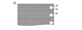
- FIG. 6 is a plan view of the crosslinkable resin film 13 ′′ of the third example.
- a groove 19 extending from the mark portion 18 ′′ to the end of the crosslinkable resin film 13 ′′ is formed.
- excess gas air or the like escapes through the groove 19, so that voids can be effectively prevented.
- each pattern (characters, etc.) constituting the mark portions 18, 18 ', 18'' preferably has an area of 10 cm 2 or less, more preferably 5 cm 2 or less.
- the structure and manufacturing method of the solar cell module using the sealing film (crosslinkable resin film) of the present invention are not particularly limited.
- the surface side transparent protective member 11 is usually a glass substrate such as silicate glass.
- the thickness of the glass substrate is generally from 0.1 to 10 mm, and preferably from 0.3 to 5 mm.
- the glass substrate may generally be chemically or thermally strengthened.
- the back side protective member 12 is preferably a plastic film such as polyethylene terephthalate (PET) or polyamide. Further, a film obtained by laminating a fluorinated polyethylene film, particularly a fluorinated polyethylene film / Al / fluorinated polyethylene film in this order in consideration of heat resistance and wet heat resistance may be used. In the case of a solar cell module having a double glass structure, a glass plate may be used.
- the solar cell sealing film of the present invention is not limited to a solar cell module using a single-crystal or polycrystalline silicon crystal solar cell as shown in FIG. It can also be used for a sealing film of a thin film solar cell module such as a silicon solar cell and a copper indium selenide (CIS) solar cell.
- a thin film solar cell module such as a silicon solar cell and a copper indium selenide (CIS) solar cell.
- the solar cell of the present invention is formed on a thin film solar cell element layer formed by a chemical vapor deposition method or the like on the surface of a surface side transparent protective member such as a glass substrate, a polyimide substrate, or a fluororesin transparent substrate.
- a surface side transparent protective member such as a glass substrate, a polyimide substrate, or a fluororesin transparent substrate.
- the sealing film of the present invention can also be used in a double-sided light-receiving (double glass) module in which a double-sided light-receiving cell is sandwiched between two transparent substrates.
- the cell for solar cells and a thin film solar cell element are named generically, and are called a solar cell element.
- the structure and material of the laminated glass of the present invention are not particularly limited.
- three or more substrates can be bonded using the intermediate film of the present invention.
- any one or more of the intermediate films to be used may be the crosslinkable resin film of the present invention.
- plastic films other than glass plates such as a silicate glass, an inorganic glass plate, a non-colored transparent glass plate
- PET film examples include polyethylene terephthalate (PET) film, polyethylene aphthalate (PEN) film, polyethylene butyrate film, polycarbonate (PC), and (meth) acrylic resin
- PET film is preferred.
- the thickness of the substrate is generally about 0.05 to 20 mm, and a transparent substrate having a high visible light transmittance is particularly preferable for use in laminated glass.
- the same substrate may be used for each substrate disposed on both sides of the intermediate film in the laminated glass, or different substrates may be used in combination.
- the combination of the substrates is preferably determined in consideration of the strength of the substrates and the use of the laminated glass.
- the substrate in the laminated glass of the present invention is a glass plate on one side and a plastic film on the other side, it can also be designed to have moderate performance in impact resistance, penetration resistance, transparency and the like. For this reason, for example, it can be used for glass such as window glass equipped in various vehicle bodies and buildings, or glass such as showcases and show windows.
- both of the transparent substrates are glass plates, they can be designed to exhibit particularly excellent impact resistance and improved penetration resistance, and can be used for various applications including laminated glass.
- the thickness of the plastic film is generally in the range of 0.02 to 2 mm because the thickness of the windshield is not required. A range of 0.02 to 1.2 mm is preferable.
- the thicknesses of the intermediate film and the plastic film can be changed according to the place where the glass is used.
- the glass plate used in the present invention is usually silicate glass.
- the glass plate thickness varies depending on the place where it is installed. For example, when it is used for a side glass and a fitted glass of an automobile, it is not necessary to make it as thick as a windshield, generally 0.1 to 10 mm, and preferably 0.3 to 5 mm.
- the one glass plate is chemically or thermally strengthened.
- the thickness of the glass plate is generally 0.5 to 10 mm, and preferably 1 to 8 mm.
- the laminated glass of the present invention has a plastic film as a substrate, it is preferable to further have a hard coat layer on the surface of the plastic film. Thereby, scratch resistance can be imparted to the laminated glass.
- composition used for the production of the crosslinkable resin films 13, 13 ′ and 13 ′′ is not particularly limited, but the present invention uses a composition containing at least an olefin (co) polymer and a crosslinking agent.
- the olefin (co) polymer contained in the crosslinkable resin film of the present invention is an ethylene / ⁇ -olefin copolymer (for example, an ethylene / ⁇ -olefin copolymer polymerized using a metallocene catalyst (m-LLDPE). ), Polyethylene (for example, low density polyethylene (LDPE), linear low density polyethylene (LLDPE), etc.), olefin polymers or copolymers such as polypropylene and polybutene, and ethylene-polar monomer copolymers, etc.
- m-LLDPE metallocene catalyst
- olefin (co) polymer it means a copolymer of olefin and a polar monomer, and has adhesiveness and transparency required for a sealing film for solar cells and an intermediate film for laminated glass.
- olefin (co) polymer one of these may be used, or two or more may be mixed and used.
- olefin (co) polymer ethylene / ⁇ -olefin copolymer, low density polyethylene (LDPE), linear low density polyethylene (LLDPE), polypropylene, polybutene, and ethylene-polar monomer copolymer
- LDPE low density polyethylene
- LLDPE linear low density polyethylene
- polypropylene polybutene
- ethylene-polar monomer copolymer It is preferably at least one polymer selected from the group consisting of:
- an ethylene-polar monomer copolymer and / or an ethylene / ⁇ -olefin copolymer are particularly preferable because a crosslinkable resin film having excellent processability and high adhesiveness can be formed.
- the melting point of the olefin (co) polymer is preferably 50 to 100 ° C. from the viewpoint of processability and the like.
- the melting point of the olefin (co) polymer refers to a melting peak temperature in heat flux differential scanning calorimetry according to JIS K7121.
- the softening point (Vicat softening point, JIS K 7206) of the olefin (co) polymer is preferably 40 to 170 ° C., more preferably 55 to 50 ° C. in consideration of kneadability at the time of blending and moldability of the mark portion 18. 150 ° C., particularly preferably 65 ° C. to 140 ° C.
- the density of the olefin (co) polymer is preferably 0.80 to 1.0 g / cm 3 , more preferably 0.85 to 0.95 g / cm 3 , and particularly preferably 0.88 to 0.95 g / cm 3. It is preferable that a certain degree of flexibility can be obtained to prevent cell cracking.
- the melt flow rate specified by JIS K7210 of olefin (co) polymer is preferably 2 to 30 g / 10 min.
- the melt flow rate (MFR) is measured based on conditions of 190 ° C. and a load of 2.16 kg according to JIS K7210.
- Examples of the polar monomer of the ethylene-polar monomer copolymer include unsaturated carboxylic acid, its salt, its ester, its amide, vinyl ester, carbon monoxide and the like. More specifically, unsaturated carboxylic acids such as acrylic acid, methacrylic acid, fumaric acid, itaconic acid, monomethyl maleate, monoethyl maleate, maleic anhydride, itaconic anhydride, lithium of these unsaturated carboxylic acids, sodium, Salts of monovalent metals such as potassium, salts of polyvalent metals such as magnesium, calcium and zinc, methyl acrylate, ethyl acrylate, isopropyl acrylate, isobutyl acrylate, n-butyl acrylate, isooctyl acrylate, methacrylic acid Examples include unsaturated carboxylic acid esters such as methyl, ethyl methacrylate, isobutyl methacrylate, and dimethyl maleate, vinyl esters such
- ethylene-polar monomer copolymer examples include ethylene-acrylic acid copolymers, ethylene-unsaturated carboxylic acid copolymers such as ethylene-methacrylic acid copolymers, and ethylene-unsaturated carboxylic acids.
- Ionomers in which some or all of the carboxyl groups of the copolymer are neutralized with the above metals ethylene-methyl acrylate copolymers, ethylene-ethyl acrylate copolymers, ethylene-methyl methacrylate copolymers, ethylene- Isobutyl acrylate copolymer, ethylene-unsaturated carboxylic acid ester copolymer such as ethylene-n-butyl acrylate copolymer, ethylene-isobutyl acrylate-methacrylic acid copolymer, ethylene-n-butyl acrylate -Ethylene-unsaturated carboxylic acid ester-unsaturated carbo such as methacrylic acid copolymer
- Typical examples include acid copolymers and ionomers in which some or all of the carboxyl groups have been neutralized with the above metals, ethylene-vinyl ester copolymers such as ethylene-vinyl acetate copolymers
- ethylene-polar monomer copolymers examples include ethylene-vinyl acetate copolymer (EVA), ethylene-methyl methacrylate copolymer (EMMA), ethylene-ethyl methacrylate copolymer, and ethylene-methyl acrylate copolymer.
- EVA ethylene-vinyl acetate copolymer
- EMMA ethylene-methyl methacrylate copolymer
- EVA ethylene-ethyl methacrylate copolymer
- ethylene-methyl acrylate copolymer examples include ethylene-methyl acrylate copolymer.
- An ethylene-ethyl acrylate copolymer is preferable, and EVA is particularly preferable.
- the content of vinyl acetate in EVA is preferably 10 to 35% by mass, particularly 10 to 30% by mass, and more preferably 10 to 25% by mass. If the vinyl acetate content is less than 10% by mass, the adhesiveness of the crosslinkable resin film may not be sufficient. May cause glass discoloration.
- the ethylene / ⁇ -olefin copolymer is composed mainly of ethylene-derived structural units, and further has an ⁇ -olefin having 3 to 12 carbon atoms such as propylene, 1-butene, 1-hexene, 1-octene, 4- Ethylene / ⁇ -olefin copolymers having one or more structural units derived from methylpentene-1,4-methyl-hexene-1,4,4-dimethyl-pentene-1, etc. (including terpolymers, etc.) ).
- the ethylene / ⁇ -olefin copolymer examples include an ethylene / 1-butene copolymer, an ethylene / 1-octene copolymer, an ethylene-4-methyl-pentene-1 copolymer, an ethylene / butene / hexene copolymer. Center polymers, ethylene / propylene / octene terpolymers, ethylene / butene / octene terpolymers, and the like.
- the content of ⁇ -olefin in the ethylene / ⁇ -olefin copolymer is preferably 5 to 40% by mass, more preferably 10 to 35% by mass, and still more preferably 15 to 30% by mass. If the ⁇ -olefin content is low, the crosslinkable resin film may not have sufficient flexibility and impact resistance, and if it is too high, the heat resistance may be low.
- ethylene / ⁇ -olefin copolymer those polymerized using a Ziegler-Natta catalyst or a metallocene catalyst can be used, and in particular, a linear ethylene / ⁇ -olefin copolymer is preferably used. can do.
- m-LLDPE ethylene / ⁇ -olefin copolymer
- metallocene catalyst it is particularly preferable to use an ethylene / ⁇ -olefin copolymer (hereinafter also referred to as m-LLDPE) polymerized with a metallocene catalyst. Since m-LLDPE has a sharp molecular weight distribution, it is excellent in processability.
- the metallocene catalyst a known metallocene catalyst may be used, and there is no particular limitation.
- the metallocene catalyst is generally a compound having a structure in which a transition metal such as titanium, zirconium or hafnium is sandwiched between unsaturated cyclic compounds containing a ⁇ -electron cyclopentadienyl group or a substituted cyclopentadienyl group. And a promoter such as an aluminum compound such as alkylaluminoxane, alkylaluminum, aluminum halide, and alkylaluminum halide.
- Metallocene catalysts are characterized by a uniform active site (single site catalyst), and usually a polymer having a narrow molecular weight distribution and an approximately equal comonomer content of each molecule is obtained.
- the density of m-LLDPE (according to JISK7112, hereinafter the same) is preferably 0.86 to 0.93 g / cm 3, more preferably 0.87 to 0.89 g / cm 3 .
- m-LLDPE commercially available m-LLDPE may be used.
- Harmolex series Kernel series manufactured by Nippon Polyethylene Co., Ltd., Evolution series manufactured by Prime Polymer Co., Ltd., Excellen GMH series, Excellen FX series manufactured by Sumitomo Chemical Co., Ltd. and the like can be mentioned.
- the above listed olefin (co) polymers may be used alone or in combination of two or more.
- the crosslinkable resin film of the present invention contains a crosslinker. At the time of manufacturing a solar cell module or laminated glass, the sealing ability and adhesion ability are improved by forming a cross-linked structure of the olefin (co) polymer.
- a crosslinking agent an organic peroxide or a photopolymerization initiator is preferably used. Among these, it is preferable to use an organic peroxide because a crosslinkable resin film having improved temperature dependency of adhesive strength, moisture resistance, and penetration resistance can be obtained.
- Any organic peroxide may be used as long as it decomposes at a temperature of 100 ° C. or higher to generate radicals.
- the organic peroxide is generally selected in consideration of the film formation temperature, the adjustment conditions of the composition, the curing temperature, the heat resistance of the adherend, and the storage stability.
- the one having a decomposition temperature of 70 ° C. or more with a half-life of 10 hours is preferable.
- those having a 10-hour half-life temperature of 90 to 120 ° C. are preferred.
- the one minute half-life temperature of the organic peroxide is preferably 140 ° C. or more, and particularly preferably one minute half-life temperature is 150 to 210 ° C., more preferably 160 to 190 ° C.
- organic peroxide examples include, from the viewpoint of processing temperature and storage stability of the resin, for example, benzoyl peroxide curing agent, tert-hexyl peroxypivalate, tert-butyl peroxypivalate, 3, 5, 5- Trimethylhexanoyl peroxide, di-n-octanoyl peroxide, lauroyl peroxide, stearoyl peroxide, 1,1,3,3-tetramethylbutylperoxy-2-ethylhexanoate, succinic acid peroxide, 2,5-dimethyl-2,5-di (tert-butylperoxy) hexane, 2,5-dimethyl-2,5-di (2-ethylhexanoylperoxy) hexane, 1-cyclohexyl-1-methylethyl Peroxy-2-ethylhexanoate, tert-hexylpa Oxy-2-ethylhexano
- the benzoyl peroxide-based curing agent any one can be used as long as it decomposes at a temperature of 70 ° C. or higher and generates radicals.
- the decomposition temperature at a half-life of 10 hours is 50 ° C. or higher and the half-life is 1 minute.
- the decomposition temperature is preferably 100 ° C. or higher, and can be appropriately selected in consideration of the preparation conditions, the film forming temperature, the curing (bonding) temperature, the heat resistance of the adherend, and the storage stability.
- Usable benzoyl peroxide curing agents include, for example, benzoyl peroxide, 2,5-dimethylhexyl-2,5-bisperoxybenzoate, p-chlorobenzoyl peroxide, m-toluoyl peroxide, 2, Examples include 4-dichlorobenzoyl peroxide and t-butyl peroxybenzoate.
- the benzoyl peroxide curing agent may be used alone or in combination of two or more.
- organic peroxide 2,5-dimethyl-2,5-di (tert-butylperoxy) hexane or tert-butylperoxy-2-ethylhexyl monocarbonate is particularly preferable. Thereby, it bridge
- the content of the organic peroxide used in the crosslinkable resin film is preferably 0.1 to 5 parts by mass, more preferably 0.2 to 2 parts by mass with respect to 100 parts by mass of the olefin (co) polymer. Preferably there is. If the content of the organic peroxide is small, the crosslinking rate of the olefin (co) polymer is slow, and if it is large, the crosslinking reaction may proceed excessively when the mark portion 18 is formed.
- photopolymerization initiator any known photopolymerization initiator can be used, but a photopolymerization initiator having good storage stability after blending is desirable.
- photopolymerization initiators include 2-hydroxy-2-methyl-1-phenylpropan-1-one, 1-hydroxycyclohexyl phenyl ketone, and 2-methyl-1- (4- (methylthio) phenyl).
- Acetophenones such as -2-morpholinopropane-1, benzoins such as benzyldimethylketal, benzophenones such as benzophenone, 4-phenylbenzophenone and hydroxybenzophenone, thioxanthones such as isopropylthioxanthone and 2-4-diethylthioxanthone, As other special ones, methylphenylglyoxylate can be used. Particularly preferably, 2-hydroxy-2-methyl-1-phenylpropan-1-one, 1-hydroxycyclohexyl phenyl ketone, 2-methyl-1- (4- (methylthio) phenyl) -2-morpholinopropane-1, Examples include benzophenone.
- photopolymerization initiators may contain one or more known photopolymerization accelerators such as benzoic acid-based or tertiary amine-based compounds such as 4-dimethylaminobenzoic acid, if necessary. Can be mixed and used. Moreover, it can be used individually by 1 type of only a photoinitiator, or 2 or more types of mixture.
- the content of the photopolymerization initiator is 0.1 to 5 parts by mass, preferably 0.2 to 3 parts by mass with respect to 100 parts by mass of the olefin (co) polymer.
- the crosslinkable resin film of the present invention preferably further contains a crosslinking aid.
- the crosslinking aid can improve the gel fraction of the olefin (co) polymer and improve the adhesion and weather resistance of the crosslinkable resin film.
- the content of the crosslinking aid is usually 0.1 to 5 parts by weight, preferably 0.1 to 3 parts by weight, particularly preferably 0.3 to 2.0 parts by weight based on 100 parts by weight of the olefin (co) polymer. Used in parts by mass. Thereby, a crosslinkable resin film having further improved hardness after crosslinking can be obtained.
- crosslinking aid compound having a radical polymerizable group as a functional group
- examples of the crosslinking aid include trifunctional crosslinking aids such as triallyl cyanurate and triallyl isocyanurate, and (meth) acrylic esters (eg, NK ester) ) Monofunctional or bifunctional crosslinking aids.
- trifunctional crosslinking aids such as triallyl cyanurate and triallyl isocyanurate, and (meth) acrylic esters (eg, NK ester) ) Monofunctional or bifunctional crosslinking aids.
- triallyl cyanurate and triallyl isocyanurate are preferable, and triallyl isocyanurate is particularly preferable.
- the crosslinkable resin film of the present invention may further contain an adhesion improver.
- an adhesion improver a silane coupling agent can be used. Thereby, it can be set as the crosslinkable resin film which has the further outstanding adhesive force.
- the silane coupling agent include ⁇ -chloropropyltrimethoxysilane, vinyltriethoxysilane, vinyltris ( ⁇ -methoxyethoxy) silane, ⁇ -methacryloxypropyltrimethoxysilane, vinyltriacetoxysilane, and ⁇ -glycidoxypropyl.
- the content of the silane coupling agent in the crosslinkable resin film of the present invention is preferably 5 parts by mass or less, preferably 0.1 to 2 parts by mass with respect to 100 parts by mass of the olefin (co) polymer.
- the crosslinkable resin film of the present invention is used for improving or adjusting various physical properties of the film (optical properties such as mechanical strength and transparency, heat resistance, light resistance, crosslinking speed, etc.), particularly for improving mechanical strength. If necessary, it may further contain various additives such as a plasticizer, an acryloxy group-containing compound, a methacryloxy group-containing compound and / or an epoxy group-containing compound.
- one or more fillers selected from titanium dioxide, calcium carbonate, aluminum oxide, and the like, preferably titanium dioxide, can be added to the crosslinkable resin film.
- a filler is particularly preferable for use as a back surface side sealing film of a solar cell.
- the average particle size of the filler is preferably 0.01 ⁇ m to 10 ⁇ m, preferably 0.3 ⁇ m to 10 ⁇ m, more preferably 0.4 ⁇ m to 10 ⁇ m, particularly 0.5 ⁇ m to 5 ⁇ m.
- the average particle diameter is a value calculated from the particle diameter measured by the laser diffraction / scattering method (JIS Z 8819).
- the addition amount of the filler is not particularly limited, but is preferably 0.1 to 20 parts by mass, more preferably 0.5 to 10 parts by mass, particularly 0.5 to 100 parts by mass of the olefin (co) polymer. Is 5 parts by mass. Within this range, even when the filler is well dispersed and the white filler is used, the cross-linkable resin film 13 itself has little whitened color, so the mark portion 18 and the uneven portion 16 can be easily distinguished. become.
- This laser processing machine is a carbon dioxide laser device (wavelength 10.6 ⁇ m) using carbon dioxide as a medium, and its output is 60 W.
- the mark surface was formed by changing the surface temperature of the processed surface.
- the pattern was evaluated as ⁇ when the pattern was visually identifiable and as x when the pattern was not identifiable.
- the crosslinkable resin film after the mark portion formation was analyzed by differential scanning calorimetry (DSC), and the one having no difference from the DSC curve before the mark portion formation (the crosslinker was not decomposed) The quality was evaluated as x with a difference.
- DSC differential scanning calorimetry
- the pattern can be clearly identified if it is equal to or higher than the minimum heating temperature (62 ° C.) obtained by subtracting 10 ° C. from the melting point of EVA (72 ° C.). Further, it was confirmed that even when the surface temperature when heating the processed surface is the same, the quality is hardly deteriorated by the laser irradiation method.
Landscapes
- Engineering & Computer Science (AREA)
- Mechanical Engineering (AREA)
- Photovoltaic Devices (AREA)
- Electroluminescent Light Sources (AREA)
- Manufacture Of Macromolecular Shaped Articles (AREA)
- Laminated Bodies (AREA)
Abstract
マーク部付の架橋性樹脂膜を提供する。 オレフィン(共)重合体及び架橋剤を含み、表面及び裏面のうち少なくとも一方の面が凹凸加工された架橋性樹脂膜の、当該凹凸加工がされた加工面を部分的に加熱溶融してマーク部を形成し、マーク付の架橋性樹脂膜を製造する。
Description
本発明は、架橋性の樹脂膜に関し、特に、太陽電池モジュールに使用される太陽電池用封止膜や、基材の貼り合せ用の中間膜に好適な架橋性樹脂膜に関する。
オレフィン(共)重合体及び架橋剤を含む架橋性樹脂膜は、透明性、接着性等に優れていることから、太陽電池用封止膜、合わせガラス等の基材貼り合せ用中間膜の他、光学フィルタを表示装置に接着する接着フィルムとして広く用いられている。
例えば、太陽電池モジュールは、一般に、図1に示すように、ガラス基板等からなる表面側透明保護部材11、表面側封止膜13A、シリコン結晶系セルなどの太陽電池素子14、裏面側封止膜13B、及び裏面側保護部材(バックカバー)12をこの順で積層し、加熱加圧して表面側封止膜13A及び裏面側封止膜13Bを架橋硬化させて接着一体化することにより製造される。
これら封止膜等に使用する架橋性樹脂膜のベースは特に限定されないが、例えば、オレフィン(共)重合体が用いられており、中でも、エチレン-酢酸ビニル共重合体(EVA)やエチレン-メタクリル酸メチル共重合体(EMMA)等のエチレン-極性モノマー共重合体やエチレン・α-オレフィン共重合体等が絶縁性や封止性に優れるため一般に用いられている。
上記のようなオレフィン(共)重合体やその他添加剤の種類及び/又は量は、太陽電池の電気的特性や、合わせガラスの透明性等を損なわない範囲で適宜変更可能であり、その膜厚もモジュール等の構造によって変えることがある。従って、使用目的にあわせ、架橋性樹脂膜の種類を適宜選択して使用するが、架橋性樹脂膜は通常透明又は半透明であって、その外観で種類を識別することができない。
架橋性樹脂膜のうち、太陽電池用封止膜を識別する方法としては、封止膜(封止膜用シート)の端部を、波型、鋸刃型等の非直線状に切断したものが公知である(特許文献1)。この方法によれば、封止膜を着色(印刷)することなく識別可能になる。
架橋性樹脂膜は、通常、長尺(テープ状)に形成された後、ロール状に巻き取られて搬送・保管されるが、特許文献1のように、端部を非直線状に切断する場合はインラインでの連続生産性が悪く、歩留りも悪いという問題があった。
また、長尺の架橋性樹脂膜では、その長手方向に沿った端部(巻き取り軸線と交差する辺)が切断されて非直線状となるが、このような架橋性樹脂膜をロール状に巻き取ると、架橋性樹脂膜端部の切断部分と非切断部分とで巻き取り厚さ(ロール径)に差が生じる。その結果、巻き取り張力にばらつきが生じ、非直線状の端部で封止膜に皺や破損が生じやすくなる。
したがって、本発明は、架橋性樹脂膜にダメージを与えずに、容易に識別可能なマークを提供することを目的とする。
また、本発明の目的は、この架橋性樹脂膜を用いた太陽電池用封止膜、太陽電池モジュール、基材貼り合せ用中間膜、基材貼り合せ方法を提供することにある。
上記目的は、オレフィン(共)重合体及び架橋剤を含み、表面及び裏面のうち少なくとも一方の面が凹凸加工された架橋性樹脂膜の、当該凹凸加工がされた加工面を部分的に加熱溶融してマーク部を形成することを特徴とする架橋性樹脂膜の製造方法により達成される。
この方法によれば、マーク部では凹凸が溶融して平坦化するので、マーク部の形状がその周囲(凹凸が残った部分、凹凸部)から浮かび上がって目視で認識可能になる。すなわち、インク等の着色剤を使用しなくてもマーク部が形成可能であり、また、架橋性樹脂膜の端部を切断する必要もないから、架橋性樹脂膜が破損し難い。
本発明の架橋性樹脂膜製造方法の好ましい態様は以下のとおりである。
(1)前記オレフィン(共)重合体の融点から10℃を引いた温度を最低加熱温度とし、当該最低加熱温度以上の温度に前記加工面を加熱して前記マーク部を形成する。これにより、短時間で確実にマーク部を平坦化可能である。
(2)前記架橋剤の1分間半減期温度を最高加熱温度とし、当該最高加熱温度以下の温度に前記加工面を加熱して前記マーク部を形成する。これにより、架橋性樹脂膜の架橋反応を抑制可能である。
(3)前記加工面にレーザーを照射して加熱する。これにより、他の加熱方法と比較して、短時間でマーク部の平坦化が可能になり、マーク部以外のダメージが少なくなる。
(4)前記レーザーとして、炭酸ガスレーザーを用いる。炭酸ガスレーザーは出力の調整が容易で、加工面の温度制御が容易である。
(5)凹凸が形成された部分の算術平均粗さが1.0μm以上300μm以下である前記加工面を加熱して前記マークを形成する。これにより、架橋性樹脂膜を重ねあわせたときのブロッキングが効果的に抑制され、かつ、マーク部と凹凸部との目視での区別が容易になる。
また、上記目的は、オレフィン(共)重合体及び架橋剤を含み、表面及び裏面のうち少なくとも一方の面には、凹凸が形成された凹凸部と、前記凹凸部よりも平坦化されたマーク部とを有することを特徴とする架橋性樹脂膜によっても達成される。
この架橋性樹脂膜では、前記凹凸部の算術平均粗さが1.0μm以上300μm以下であり、前記マーク部の算術平均粗さは、前記凹凸部の算術平均粗さよりも小さいことが好ましい。
更に、上記目的は、上記方法により太陽電池用封止膜を製造する方法、当該太陽電池用封止膜で太陽電池素子を封止する太陽電池モジュールの製造方法、架橋性樹脂膜からなる太陽電池用封止膜、当該封止膜で太陽電池素子を封止した太陽電池モジュール、上記方法により基材貼り合せ用中間膜を製造する方法、当該中間膜で基材を貼り合せて積層体を製造する積層体の製造方法、架橋性樹脂膜からなる基材貼り合せ用中間膜、並びに、当該中間膜で基材を貼り合せた積層体によっても達成される。
本発明によれば、架橋性樹脂膜にダメージを与えることなくマーク部を形成可能であり、また、この架橋性樹脂膜を太陽電池用封止膜や基材貼り合せ用中間膜に用いた場合に、貼り合せ欠陥や汚染も起こり難い。
以下、本発明を詳細に説明する。
本発明は、先ず、架橋性樹脂膜の製造方法及び架橋性樹脂膜に関するものであって、架橋性樹脂膜の製造方法は、主に、
(A)少なくとも一方の面に凹凸が形成されたシート状の架橋性樹脂膜を製造する工程と、
(B)凹凸が形成された面(加工面)にマークを形成する工程と、
を有する。
(A)少なくとも一方の面に凹凸が形成されたシート状の架橋性樹脂膜を製造する工程と、
(B)凹凸が形成された面(加工面)にマークを形成する工程と、
を有する。
市販の架橋性樹脂膜をそのまま(B)工程に用いて(A)工程を省略しても良いし、市販の架橋性樹脂膜に凹凸加工を施した後に(B)工程に用いてもよいが、以下に一般的な(A)工程を説明する。
(A)工程は、架橋性樹脂膜をシート状に成形する工程(a)と、その表面及び/又は裏面に凹凸を形成する工程(b)とを有する。
(a)工程
シート状の架橋性樹脂膜は公知の方法に準じて製造することができる。例えば、オレフィン(共)重合体と架橋剤とを含有する組成物を、通常の押出成形、又はカレンダ成形(カレンダリング)等により成形してシート状物を得る方法により製造することができる。成形時の温度は、架橋剤が反応しないかほとんど反応しない温度、好ましくは架橋剤の1分間半減期温度以下で行う。押出成形ではダイ付近における温度上昇により架橋剤の分解が進行する場合があるため、カレンダ成形により行うことが好ましい。
シート状の架橋性樹脂膜は公知の方法に準じて製造することができる。例えば、オレフィン(共)重合体と架橋剤とを含有する組成物を、通常の押出成形、又はカレンダ成形(カレンダリング)等により成形してシート状物を得る方法により製造することができる。成形時の温度は、架橋剤が反応しないかほとんど反応しない温度、好ましくは架橋剤の1分間半減期温度以下で行う。押出成形ではダイ付近における温度上昇により架橋剤の分解が進行する場合があるため、カレンダ成形により行うことが好ましい。
図2(a)の符号13は、シート状物である架橋性樹脂膜を示している。押出し成形、カレンダリング等のシート成形直後の状態では、通常、架橋性樹脂膜13の表面及び裏面は平滑である。次に、この架橋性樹脂膜13に凹凸を形成する工程(b)を説明する。
(b)工程
架橋性樹脂膜13の表面及び裏面のうち、少なくとも一方の面(好ましくは一方)を加工面25とし、この加工面25に凹凸加工を施す。凹凸加工法は特に限定されず、エッチング、コロナ放電、レーザー照射、エンボス加工等種々の方法を採用することができるが、架橋性樹脂膜13の熱ダメージを考慮すると、エンボス加工のように、架橋性樹脂膜13に凹凸型を押し当てる方法が最も好ましい。エンボス加工は特に限定されないが、例えば、架橋性樹脂膜13を複数本のロール(エンボスロール、加圧ロール)の間に通して加工する。少なくとも1本のロール(エンボスロール)の側面には凹凸が形成されており、この凹凸に架橋性樹脂膜13が押し付けられ、架橋性樹脂膜13の表面にロールの凹凸が反転した形状の凹凸模様(エンボス)が形成される。
架橋性樹脂膜13の表面及び裏面のうち、少なくとも一方の面(好ましくは一方)を加工面25とし、この加工面25に凹凸加工を施す。凹凸加工法は特に限定されず、エッチング、コロナ放電、レーザー照射、エンボス加工等種々の方法を採用することができるが、架橋性樹脂膜13の熱ダメージを考慮すると、エンボス加工のように、架橋性樹脂膜13に凹凸型を押し当てる方法が最も好ましい。エンボス加工は特に限定されないが、例えば、架橋性樹脂膜13を複数本のロール(エンボスロール、加圧ロール)の間に通して加工する。少なくとも1本のロール(エンボスロール)の側面には凹凸が形成されており、この凹凸に架橋性樹脂膜13が押し付けられ、架橋性樹脂膜13の表面にロールの凹凸が反転した形状の凹凸模様(エンボス)が形成される。
図2(b)は、加工面25に凹凸が形成された架橋性樹脂膜13を示している。凹又は凸の平面形状は特に限定されず、例えば、格子、網目、ダイヤ、円(真円、楕円)、すじ、矩形(正方形、長方形)でもよい。加工面25の一部で凹凸の平面形状を変えてもよいが、加工性の面からは、平面形状が略等しい凹及び/又は凸を均一に分布させる。
加工面25の凹凸が形成された部分の算術平均粗さRa(JIS-B0601(2001))は、1.0μm~300μmが好ましく、より好ましくは1.0~100μm、特に好ましくは1.0~50μmである。この表面粗さ(算術平均粗さ)が小さすぎると、架橋性樹脂膜13同士を重ね合せたときにブロッキングが生じやすくなり、大きすぎると、後述するマーク部を形成したときに、マーク部と凹凸部との境界が不鮮明になる。
架橋性樹脂膜13の膜厚は特に限定されないが、凹凸加工後の膜厚は50μm~2mmが好ましく、より好ましくは200μm~1.0mmである。架橋性樹脂膜13が薄すぎると、機械的強度が弱くなる上、(B)工程の加熱で架橋性樹脂膜13の深部までダメージがおよぶことがあり、架橋性樹脂膜13が厚すぎると、薄膜化が要求されるモジュールの製造には適さない。
次に、この架橋性樹脂膜13にマークを形成する工程(B)について説明する。
次に、この架橋性樹脂膜13にマークを形成する工程(B)について説明する。
(B)工程
本発明では、加工面25を部分的に加熱してマークを形成する。加熱方法は特に限定されないが、ホットスタンプ法、レーザー照射法、加熱ロールによるニップ加工等の加熱法を、単独又は組み合わせて使用する。
本発明では、加工面25を部分的に加熱してマークを形成する。加熱方法は特に限定されないが、ホットスタンプ法、レーザー照射法、加熱ロールによるニップ加工等の加熱法を、単独又は組み合わせて使用する。
ホットスタンプ法及びニップ加工法は熱伝導による加熱法である。ホットスタンプ法は、通常、凸部が形成された版型(スタンパ)を用いる。この凸部は、平面形状が、形成すべきマークが反転した形状(鏡文字、平面形状がマークの形状と左右対称)になっている。加熱手段で加熱したスタンパを、架橋性樹脂膜13に対し相対的に移動させて、その凸部の先端を架橋性樹脂膜13の加工面25に押し当てることで、加工面25が熱伝導により加熱される。
他方、レーザー照射法は、所望波長のレーザー光9を、加工面25に照射して加熱する方法である(図2(c))。レーザー照射法は、短時間で効率良く加熱可能であるから、ホットスタンプ法やニップ加工よりも本発明に適している。
レーザーの種類は特に限定されず、公知のレーザー装置を使用可能であり、例えば、
‐CO2(炭酸ガス)、He-Ne、エキシマ、アルゴンからなる群より選択される気体を媒質とする気体レーザー;
‐YAG(イットリウム・アルミニウム・ガーネット)、YVO(イットリウム・バナデイト)、Yb(イッテルビウム)からなる群より選択される固体を媒質とする固体レーザー;
‐AlGaAs/GaAs系、GaInAsP/InP系からなる群より選択される半導体を媒質とする半導体レーザー;又は、
‐アルコール等の溶媒に色素を溶解した液体を媒質とする液体レーザー
を用いることができる。これらのレーザーは1種類を用いてもよいし、マークの形状・サイズに応じて2種類以上を組み合わせて使用してもよい。
‐CO2(炭酸ガス)、He-Ne、エキシマ、アルゴンからなる群より選択される気体を媒質とする気体レーザー;
‐YAG(イットリウム・アルミニウム・ガーネット)、YVO(イットリウム・バナデイト)、Yb(イッテルビウム)からなる群より選択される固体を媒質とする固体レーザー;
‐AlGaAs/GaAs系、GaInAsP/InP系からなる群より選択される半導体を媒質とする半導体レーザー;又は、
‐アルコール等の溶媒に色素を溶解した液体を媒質とする液体レーザー
を用いることができる。これらのレーザーは1種類を用いてもよいし、マークの形状・サイズに応じて2種類以上を組み合わせて使用してもよい。
特に、可視光よりも長波長のレーザー光(波長780nm以上)が好ましく、より好ましいレーザー波長は1000nm以上(1μm以上)、更に好ましくは2.0μm以上、特に10μm以上である。
最も好ましいレーザー光9は、波長が10μmを超える炭酸ガスレーザーである(例:波長10.6μm)。このような長波長レーザーは、樹脂の加熱効率が高い上、短波長(例:780nm未満)のレーザー光と比較して、低エネルギー(W)であるため、出力調整が容易で、加熱温度を制御がしやすいという利点がある。
加工面25に照射するレーザー光9の出力を調整し、或いは、スタンパの加熱手段を制御して、加工面25を所望の加熱温度に加熱する。この加熱温度は、架橋性樹脂膜13に使用したオレフィン(共)重合体により決定され、好ましくは、
Mp-10℃
(Mpはオレフィン(共)重合体の融点であって、2種以上のオレフィン(共)重合体を混合して使用する場合はその混合物の融点であり、いずれの場合も示差走査熱量測定装置(DSC)にて測定した値である)
で示される温度(最低加熱温度)を下限とする。加熱温度の上限は特に限定されないが、架橋性樹脂膜13に使用した架橋剤の1分間半減期温度(最高加熱温度)以下の温度で加熱する。
Mp-10℃
(Mpはオレフィン(共)重合体の融点であって、2種以上のオレフィン(共)重合体を混合して使用する場合はその混合物の融点であり、いずれの場合も示差走査熱量測定装置(DSC)にて測定した値である)
で示される温度(最低加熱温度)を下限とする。加熱温度の上限は特に限定されないが、架橋性樹脂膜13に使用した架橋剤の1分間半減期温度(最高加熱温度)以下の温度で加熱する。
この加熱温度は、オレフィン(共)重合体の軟化点Spの近傍がより好ましく、更に好ましくは、Sp-20℃を下限とし、Sp+20℃を上限とする。ここで、軟化点とは、JIS K 7206で測定されるビカット軟化点のことであり、オレフィン(共)重合体が2種以上の樹脂の混合物の場合、その混合物の軟化点を意味する。
上記のような加熱温度で加工面25を加熱し、架橋性樹脂膜13の表層部分(凹凸部分)のみを溶融させ、その下層部分で架橋剤の熱分解が開始する前(架橋反応開始前)に加熱を終了し、必要であれば架橋性樹脂膜13を冷却する。レーザー照射法により加熱する場合、レーザー光9は凹凸により一部反射、散乱するため、表層部分のみを短時間で溶融可能である。
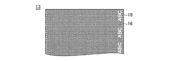
図2(d)、図3は、加工面25の表層が部分的に溶融して平坦化した状態を示しており、その平坦化した部分でマーク部18が形成され、その周囲は凹凸が残った凹凸部16となっている。凹凸の除去によりマーク部18には架橋性樹脂膜13自体の色(例:透明、半透明、白以外の色で着色)が露出しているのに対し、凹凸部16では可視光が散乱して白濁し、目視では、架橋性樹脂膜13の色に白が加色されている。
この色の差異でマーク部18が凹凸部16から区別され、マーク部18の平面形状(輪郭)を目視で認識可能となる。マーク部18は、通常、1以上の模様(文字、数字、図形、記号を含む)で構成され、これら模様が、単独又は組み合わされて1以上の情報(型番、材料、品質、寸法、社名、日時、バーコード、QRコード(登録商標)等)を構成する。すなわち、マーク部18の形状を観察することで、架橋性樹脂膜13に付与された固有の情報を取得することができる。
図4の符号2は、長尺状の架橋性樹脂膜13を巻き回したロールを示している。本発明の架橋性樹脂膜13は、凹凸(表層)のみを除去してマーク部18を形成しているから、膜厚分布が均一であり、ロール巻き取り張力にばらつきが生じず、皺や破れ等の破損が生じ難い。
また、架橋性樹脂膜13の加工面25には凹凸部16が残存しており、好ましくは凹凸部16の面積は、加工面25(架橋性樹脂膜13片面)全面積の50%以上、好ましくは75%以上、より好ましくは90%以上、特に95%以上である。凹凸部16の面積がこの範囲であれば、ロール2のように架橋性樹脂膜13同士が密着した場合でもブロッキングが防止され、ロール2から架橋性樹脂膜13をスムーズに引き出すことができる。
次に、この架橋性樹脂膜を用いて太陽電池モジュールを製造する工程を説明する
次に、この架橋性樹脂膜を用いて太陽電池モジュールを製造する工程を説明する
<太陽電池モジュールの製造>
本発明の太陽電池モジュールの構造は、本発明の架橋性樹脂膜13を封止膜として使用し、太陽電池素子を封止した構造を含んでいれば特に制限されない。例えば、表面側透明保護部材と裏面側保護部材との間に、本発明の架橋性樹脂膜13を介在させて架橋一体化させることにより太陽電池用セルを封止させた構造などが挙げられる。
本発明の太陽電池モジュールの構造は、本発明の架橋性樹脂膜13を封止膜として使用し、太陽電池素子を封止した構造を含んでいれば特に制限されない。例えば、表面側透明保護部材と裏面側保護部材との間に、本発明の架橋性樹脂膜13を介在させて架橋一体化させることにより太陽電池用セルを封止させた構造などが挙げられる。
なお、本発明において、太陽電池用セルの光が照射される側(受光面側)を「表面側」と称し、太陽電池用セルの受光面とは反対面側を「裏面側」と称する。
架橋性樹脂膜13がロール2になっている場合は、ロール2から架橋性樹脂膜13を引き出し、所定のサイズに切断して使用する。この例では、本発明の架橋性樹脂膜13を、表面側封止膜13A、裏面側封止膜13Bとして使用するが、いずれか1以上の封止膜13A、13Bに、本発明の架橋性樹脂膜13を使用すればよい。
図1に示すように表面側透明保護部材11、表面側封止膜13A、単結晶又は多結晶シリコンセル等の太陽電池素子14、本発明の裏面側封止膜13B及び裏面側保護部材12を積層し、常法の貼合せ方法で封止膜13A、13Bを架橋硬化させる。
貼合せ方法は、加熱加圧法が好ましい。加熱により封止膜13A、13Bが軟化し、加圧により軟化した加工面25が対象物(他方の封止膜13A、13B又は保護部材11、12等)で押圧され、凹凸部16がマーク部18と略面一に平坦化される。その結果、太陽電池モジュールでは、マーク部18と凹凸部16が区別不能になり、出来上がり製品では封止膜13A、13Bの固有情報が消失する。
この貼り合せの前に封止膜13A、13Bの架橋硬化反応が完了していると、太陽電池素子14が十分に封止されず、貼り合せ欠陥となる。本発明の封止膜13A、13Bは、マーク部18を形成する際に、凹凸の下層部分で架橋反応が進行する前に加熱を終了するから、封止膜13A、13Bが未架橋である。従って、本発明の架橋性樹脂膜13を用いた場合に、貼り合せ欠陥が生じない。しかも、マーク部18には、色素等の着色剤も使用されていないから、太陽電池素子14が汚染されることもない。
以上は、本発明の架橋性樹脂膜13を太陽電池用封止膜として使用したが、本発明はこれに限定されるものではなく、多様な基材の貼り合せに架橋性樹脂膜13を用い、積層体を製造することができる。以下に、積層体の一例と、その製造方法の一例を説明する。
<合わせガラスの製造>
積層体としては、例えば合わせガラスがある。本発明の架橋性樹脂膜13を用いた合わせガラス30は、図7に示すように、少なくとも2枚の基板(基材)31A、31Bと基材貼り合せ用中間膜13Cを有し、この中間膜13Cを介して基板31A、31Bが貼り合わされている。
積層体としては、例えば合わせガラスがある。本発明の架橋性樹脂膜13を用いた合わせガラス30は、図7に示すように、少なくとも2枚の基板(基材)31A、31Bと基材貼り合せ用中間膜13Cを有し、この中間膜13Cを介して基板31A、31Bが貼り合わされている。
この合わせガラスを作成するには、本発明の架橋性樹脂膜13を中間膜13Cとして用いることが好ましく、その製造方法は特に限定されないが、例えば、必要であれば適切なサイズに切断した架橋性樹脂膜13(中間膜13C)を、基板31A、31Bの間に挟持して積層体とし、この積層体を必要であれば脱気し、適切な温度(例:80~150℃)で押圧しながら加熱する(加熱圧着)。
上述したように、本発明の架橋性樹脂膜13は、マーク部18を形成する際に樹脂の架橋反応が進行しないので、基板31A、31Bと密着した状態で中間膜13Cの架橋反応が進行する。従って、貼り合せ欠陥がない合わせガラス30を製造することができる。マーク部18には着色剤等が使用されていないので、合わせガラスが着色されることがなく、また、太陽電池モジュールの場合と同様、加熱圧着時にマーク部18は消失するので、合わせガラスに要求される透明性を損なわない。
なお、合わせガラスにおける「ガラス」とは透明又は半透明基板全般を意味するものであり、着色されたものも含まれる。したがって「合わせガラス」に用いる基板は硬質板部材であれば、ガラス、プラスチック又はそれらの複合材等、その材料は特に限定されず、不透明基板を用いることもできるが、1枚以上の基板がある程度の可視光透過性(透明、半透明、着色)を備えることが好ましい。
<その他用途>
架橋性樹脂膜の用途は特に限定されない。3枚以上の基材を2枚以上の架橋性樹脂膜で貼り合せる場合(例:ガラス、PET、ガラスを記載した順番で貼り合せ)には、いずれか1枚以上の架橋性樹脂膜に、本発明の架橋性樹脂膜を用いることができる。貼り合せ対象の基材(基板)も特に限定されず、透明、不透明、半透明、着色基材を用いることが可能であり、同じ種類の基材同士を貼り合せてもよいし、2種以上の基材を貼り合せて積層体を製造することもできる。基材の種類としては、硬質基板(ガラス、プラスチック、金属)、柔軟性基板(プラスチックフィルム、布等)、電極、機能性層(フォトクロミック層、熱線遮蔽層、ハードコート層、飛散防止層、反射防止層等)等がある。
架橋性樹脂膜の用途は特に限定されない。3枚以上の基材を2枚以上の架橋性樹脂膜で貼り合せる場合(例:ガラス、PET、ガラスを記載した順番で貼り合せ)には、いずれか1枚以上の架橋性樹脂膜に、本発明の架橋性樹脂膜を用いることができる。貼り合せ対象の基材(基板)も特に限定されず、透明、不透明、半透明、着色基材を用いることが可能であり、同じ種類の基材同士を貼り合せてもよいし、2種以上の基材を貼り合せて積層体を製造することもできる。基材の種類としては、硬質基板(ガラス、プラスチック、金属)、柔軟性基板(プラスチックフィルム、布等)、電極、機能性層(フォトクロミック層、熱線遮蔽層、ハードコート層、飛散防止層、反射防止層等)等がある。
積層体の例としては、上記合わせガラスの他、1種以上の機能性層を基板に貼り合せた機能性ウィンドウ(窓ガラス等)等がある。更には、基材は板状のものに限定されず、1以上の基材が装置の一部又は全部であってもよく、例えば、液晶ディスプレイ、プラズマディスプレイ、有機ELディスプレイ等の表示装置の表面に、光学フィルタのような機能性層を貼り合せる際に、架橋性樹脂膜13を使用することができる。その他、LED等の光源装置のカバー等の製造にも、本発明の架橋性樹脂膜13を使用することができる。本発明の架橋性樹脂膜13は、基材への接着性と、積層体(一部又は全部)の透明性が要求される用途で特に好ましく使用される。
次に、本発明の架橋性樹脂膜13の他の態様を説明する。
次に、本発明の架橋性樹脂膜13の他の態様を説明する。
<マークの配置>
図3に示した第1例の架橋性樹脂膜13では、マーク部18を構成する模様(文字、図形、記号を含む)を、架橋性樹脂膜13の端部(特に長手方向に沿った端部)に沿って配置した。架橋性樹脂膜13の端部、特に架橋性樹脂膜13の縁から2cm以内の範囲にマーク部18を形成すれば、加熱工程のエラーで架橋反応が進行しても、貼り合せ工程での欠陥を最低限にとどめることができる。しかしながら、本発明はこれに限定されるものではなく、マーク部18を多様な範囲に多様な方法で設置することができる。
図3に示した第1例の架橋性樹脂膜13では、マーク部18を構成する模様(文字、図形、記号を含む)を、架橋性樹脂膜13の端部(特に長手方向に沿った端部)に沿って配置した。架橋性樹脂膜13の端部、特に架橋性樹脂膜13の縁から2cm以内の範囲にマーク部18を形成すれば、加熱工程のエラーで架橋反応が進行しても、貼り合せ工程での欠陥を最低限にとどめることができる。しかしながら、本発明はこれに限定されるものではなく、マーク部18を多様な範囲に多様な方法で設置することができる。
図5は第2例の架橋性樹脂膜13’の加工面25を示す平面図である。第2例では、マーク部18’を構成する模様(文字等)が、架橋性樹脂膜13’の幅方向端部(長手方向に沿って伸びる端部)に対し、傾斜した仮想線上に配置されている。
マーク部18’を構成する模様が大きいと(例:1つの模様(文字等、連続した1つの凹部)の面積が2cm2以上)、架橋性樹脂膜13’を巻き取った時に、マーク部18’同士が重なり合ってブロッキングが生じることがある。第2例では、マーク部18’を構成する模様が、架橋性樹脂膜13’の幅方向端部、すなわち、巻き取り時に架橋性樹脂膜13が走行する方向に対し斜めに配置されているので、マーク部18’同士の重なり合いが少なくなり、ブロッキングを効果的に防止することができる。
マーク部18’同士の重なり合いが少なくなるのであれば、その配置は特に限定されず、例えば、マーク部18’から架橋性樹脂膜13’端部迄の距離を、一以上のマーク部18’と、他の一以上のマーク部18’とで変更してもよい(図5)。
他の例として、マーク部18を構成する模様(図形等)が特に大きい場合(例:1つの模様(文字等)の面積が3cm2以上)、太陽電池モジュールの貼り合せ工程で加工面25に気泡(ボイド)が残る場合がある。
図6は第3例の架橋性樹脂膜13’’の平面図であり、この架橋性樹脂膜13’’では、マーク部18’’と同じ工程で、又は、マーク部18’’とは別の工程で、マーク部18’’から架橋性樹脂膜13’’の端部まで伸びる溝19を形成している。貼り合せの際には、この溝19を通って余分な気体(空気等)が逃げるから、ボイド残りを効果的に防止することができる。
しかしながら、マーク部18、18’、18’’の平面形状が極端に大きいと、ボイドだけではなく、ブロッキング抑制効果も低下する。従って、マーク部18、18’、18’’を構成する各模様(文字等)は、面積を10cm2以下とすることが好ましく、より好ましくは5cm2以下とする。
<太陽電池モジュール>
本発明の封止膜(架橋性樹脂膜)を用いる太陽電池モジュールの構造や製造方法は特に限定されない。
表面側透明保護部材11は、通常珪酸塩ガラスなどのガラス基板であるのがよい。ガラス基板の厚さは、0.1~10mmが一般的であり、0.3~5mmが好ましい。ガラス基板は、一般に、化学的に、或いは熱的に強化させたものであってもよい。
本発明の封止膜(架橋性樹脂膜)を用いる太陽電池モジュールの構造や製造方法は特に限定されない。
表面側透明保護部材11は、通常珪酸塩ガラスなどのガラス基板であるのがよい。ガラス基板の厚さは、0.1~10mmが一般的であり、0.3~5mmが好ましい。ガラス基板は、一般に、化学的に、或いは熱的に強化させたものであってもよい。
裏面側保護部材12は、ポリエチレンテレフタレート(PET)やポリアミドなどのプラスチックフィルムが好ましく用いられる。また、耐熱性、耐湿熱性を考慮してフッ化ポリエチレンフィルム、特にフッ化ポリエチレンフィルム/Al/フッ化ポリエチレンフィルムをこの順で積層させたフィルムでも良い。ダブルガラス構造の太陽電池モジュールの場合にはガラス板を使用してもよい。
なお、本発明の太陽電池用封止膜は、図1に示したような単結晶又は多結晶のシリコン結晶系の太陽電池用セルを用いた太陽電池モジュールだけでなく、薄膜シリコン系、薄膜アモルファスシリコン系太陽電池、セレン化銅インジウム(CIS)系太陽電池等の薄膜太陽電池モジュールの封止膜にも使用することもできる。
この場合は、例えば、ガラス基板、ポリイミド基板、フッ素樹脂系透明基板等の表面側透明保護部材の表面上に化学気相蒸着法等により形成された薄膜太陽電池素子層上に、本発明の太陽電池用封止膜、裏面側保護部材を積層し、接着一体化させた構造や、表面側透明保護部材、表面側封止膜、薄膜太陽電池素子、本発明の裏面側封止膜、及び裏面側保護部材をこの順で積層し、接着一体化させた構造等が挙げられる。更には、両面受光型セルを2枚の透明基板で挟み込んだ両面受光型(ダブルガラス)モジュールにも、本発明の封止膜を使用することができる。なお、本発明において、太陽電池用セルや薄膜太陽電池素子を総称して太陽電池素子という。
<合わせガラス>
本発明の合わせガラスの構造や材質も特に限定されない。例えば3枚以上の基板を本発明の中間膜を用いて貼り合せることもできる。3枚以上の中間膜を貼り合せに用いる場合、使用する2枚以上の中間膜のうち、いずれか1枚以上の中間膜が本発明の架橋性樹脂膜であればよい。
本発明の合わせガラスの構造や材質も特に限定されない。例えば3枚以上の基板を本発明の中間膜を用いて貼り合せることもできる。3枚以上の中間膜を貼り合せに用いる場合、使用する2枚以上の中間膜のうち、いずれか1枚以上の中間膜が本発明の架橋性樹脂膜であればよい。
合わせガラスに用いられる基板としては、特に限定されないが、例えば珪酸塩ガラス、無機ガラス板、無着色透明ガラス板などのガラス板の他、プラスチックフィルムを用いてもよい。前記プラスチックフィルムとしては、ポリエチレンテレフタレート(PET)フィルム、ポリエチレンアフタレート(PEN)フィルム、ポリエチレンブチレートフィルム、ポリカーボネート(PC)、(メタ)アクリル樹脂を挙げることができ、PETフィルムが好ましい。基板の厚さは、0.05~20mm程度が一般的であり、合わせガラスの用途では可視光透過性が高い透明基板が特に好ましい。
合わせガラスにおいて中間膜の両側に配置されるそれぞれの基板は、同一の基板を用いてもよく、異なる基板を組み合わせて用いてもよい。基板の強度と合わせガラスの用途とを考慮して、基板の組み合わせを決定するのが好ましい。
本発明の合わせガラスにおける基板が、一方がガラス板で、他方がプラスチックフィルムである場合、耐衝撃性、耐貫通性、透明性等において適度な性能を有するように設計することもできる。このため、例えば各種車体、ビル等に装備される窓ガラス等のガラス、又はショーケース、ショーウインド等のガラスに使用することができる。
また、透明基板が共にガラス板の場合は、特に優れた耐衝撃性、向上した耐貫通性を示すように設計することができ、合わせガラスを含む種々な用途に使用することができる。
一方がプラスチックフィルムの合わせガラス、例えば自動車のサイドガラス及び嵌め込みガラスの場合、フロントガラス程の厚さは必要としないため、プラスチックフィルムの厚さは、0.02~2mmの範囲が一般的であり、0.02~1.2mmの範囲が好ましい。中間膜及びプラスチックフィルムの厚さは、当該ガラスを使用する場所等に応じて変えることができる。
本発明で使用されるガラス板は、通常珪酸塩ガラスである。ガラス板厚は、フィルム強化ガラスの場合、それを設置する場所等により異なる。例えば、自動車のサイドガラス及び嵌め込みガラスに使用する場合、フロントガラスのように厚くする必要はなく、0.1~10mmが一般的であり、0.3~5mmが好ましい。前記1枚のガラス板は、化学的に、或いは熱的に強化させたものである。
自動車のフロントガラス等に適当な両方がガラス板である合わせガラスの場合は、ガラス板の厚さは、0.5~10mmが一般的であり、1~8mmが好ましい。
本発明の合わせガラスが基板としてプラスチックフィルムを有する場合、プラスチックフィルム表面にはさらにハードコート層を有するのが好ましい。これにより合わせガラスに耐傷付き性を付与することができる。
<架橋性樹脂膜の組成>
架橋性樹脂膜13、13’、13’’の製造に用いる組成物も特に限定されないが、本発明は、少なくともオレフィン(共)重合体と架橋剤とを含有する組成物を用いる。
架橋性樹脂膜13、13’、13’’の製造に用いる組成物も特に限定されないが、本発明は、少なくともオレフィン(共)重合体と架橋剤とを含有する組成物を用いる。
[オレフィン(共)重合体]
本発明の架橋性樹脂膜に含まれるオレフィン(共)重合体とは、エチレン・α-オレフィン共重合体(例えば、メタロセン触媒を用いて重合されたエチレン・α-オレフィン共重合体(m-LLDPE)等)、ポリエチレン(例えば、低密度ポリエチレン(LDPE)、直鎖状低密度ポリエチレン(LLDPE)等)、ポリプロピレン、ポリブテン等のオレフィンの重合体又は共重合体、及びエチレン-極性モノマー共重合体等のオレフィンと極性モノマーとの共重合体を意味し、太陽電池用封止膜や合わせガラス用中間膜に要求される接着性、透明性等を有するものとする。オレフィン(共)重合体として、これらの1種を用いても良く、2種以上を混合して用いても良い。本発明において、オレフィン(共)重合体としては、エチレン・α-オレフィン共重合体、低密度ポリエチレン(LDPE)、直鎖状低密度ポリエチレン(LLDPE)、ポリプロピレン、ポリブテン及びエチレン-極性モノマー共重合体からなる群から選択される少なくとも1種以上の重合体であることが好ましい。特に、加工性に優れ、接着性が高い架橋性樹脂膜を形成することができることから、エチレン-極性モノマー共重合体及び/又はエチレン・α-オレフィン共重合体が特に好ましい。
本発明の架橋性樹脂膜に含まれるオレフィン(共)重合体とは、エチレン・α-オレフィン共重合体(例えば、メタロセン触媒を用いて重合されたエチレン・α-オレフィン共重合体(m-LLDPE)等)、ポリエチレン(例えば、低密度ポリエチレン(LDPE)、直鎖状低密度ポリエチレン(LLDPE)等)、ポリプロピレン、ポリブテン等のオレフィンの重合体又は共重合体、及びエチレン-極性モノマー共重合体等のオレフィンと極性モノマーとの共重合体を意味し、太陽電池用封止膜や合わせガラス用中間膜に要求される接着性、透明性等を有するものとする。オレフィン(共)重合体として、これらの1種を用いても良く、2種以上を混合して用いても良い。本発明において、オレフィン(共)重合体としては、エチレン・α-オレフィン共重合体、低密度ポリエチレン(LDPE)、直鎖状低密度ポリエチレン(LLDPE)、ポリプロピレン、ポリブテン及びエチレン-極性モノマー共重合体からなる群から選択される少なくとも1種以上の重合体であることが好ましい。特に、加工性に優れ、接着性が高い架橋性樹脂膜を形成することができることから、エチレン-極性モノマー共重合体及び/又はエチレン・α-オレフィン共重合体が特に好ましい。
オレフィン(共)重合体の融点は加工性等の観点から50~100℃であることが好ましい。なお、本発明において、オレフィン(共)重合体の融点は、JIS K 7121に従う熱流束示差走査熱量測定における融解ピーク温度のことをいう。
オレフィン(共)重合体の軟化点(ビカット軟化点、JIS K 7206)は、配合時の混練性と、マーク部18の成型性とを考慮すると、40~170℃が好ましく、より好ましくは55~150℃、特に好ましくは65℃~140℃である。
オレフィン(共)重合体の密度は、好ましくは0.80~1.0g/cm3、より好ましくは0.85~0.95g/cm3、特に好ましくは0.88~0.95g/cm3あることが、セル割れ等を防止するのに適度な柔軟性が得られる点で好ましい。
また、オレフィン(共)重合体のJIS K7210で規定されるメルトフローレートは、2~30g/10分が好ましい。このようなメルトフローレートを有するオレフィン(共)重合体を用いることで、加熱部分の溶融が起こりやすくなり、短時間の加熱でマーク部18を形成することができる上、クッション性に優れた架橋性樹脂膜とすることができる。なお、本発明において、メルトフローレート(MFR)の値は、JIS K7210に従い、190℃、荷重2.16kgの条件に基づいて測定されたものである。
エチレン-極性モノマー共重合体の極性モノマーは、不飽和カルボン酸、その塩、そのエステル、そのアミド、ビニルエステル、一酸化炭素等を例示することができる。より具体的には、アクリル酸、メタクリル酸、フマル酸、イタコン酸、マレイン酸モノメチル、マレイン酸モノエチル、無水マレイン酸、無水イタコン酸等の不飽和カルボン酸、これら不飽和カルボン酸のリチウム、ナトリウム、カリウムなどの1価金属の塩やマグネシウム、カルシウム、亜鉛などの多価金属の塩、アクリル酸メチル、アクリル酸エチル、アクリル酸イソプロピル、アクリル酸イソブチル、アクリル酸n-ブチル、アクリル酸イソオクチル、メタクリル酸メチル、メタクリル酸エチル、メタクリル酸イソブチル、マレイン酸ジメチル等の不飽和カルボン酸エステル、酢酸ビニル、プロピオン酸ビニルのようなビニルエステル、一酸化炭素、二酸化硫黄などの一種又は二種以上などを例示することができる。
エチレン-極性モノマー共重合体として、より具体的には、エチレン-アクリル酸共重合体、エチレン-メタクリル酸共重合体のようなエチレン-不飽和カルボン酸共重合体、前記エチレン-不飽和カルボン酸共重合体のカルボキシル基の一部又は全部が上記金属で中和されたアイオノマー、エチレン-アクリル酸メチル共重合体、エチレン-アクリル酸エチル共重合体、エチレン-メタクリル酸メチル共重合体、エチレン-アクリル酸イソブチル共重合体、エチレン-アクリル酸n-ブチル共重合体のようなエチレン-不飽和カルボン酸エステル共重合体、エチレン-アクリル酸イソブチル-メタクリル酸共重合体、エチレン-アクリル酸n-ブチル-メタクリル酸共重合体のようなエチレン-不飽和カルボン酸エステル-不飽和カルボン酸共重合体及びそのカルボキシル基の一部又は全部が上記金属で中和されたアイオノマー、エチレン-酢酸ビニル共重合体のようなエチレン-ビニルエステル共重合体等を代表例として例示することができる。
エチレン-極性モノマー共重合体としては、エチレン-酢酸ビニル共重合体(EVA)、エチレン-メタクリル酸メチル共重合体(EMMA)、エチレン-メタクリル酸エチル共重合体、エチレン-アクリル酸メチル共重合体、エチレン-アクリル酸エチル共重合体が好ましく、特にEVAが好ましい。
オレフィン(共)重合体としてEVAを使用する場合、EVAにおける酢酸ビニルの含有率は10~35質量%、特に10~30質量%、さらに10~25質量%が好ましい。酢酸ビニルの含有量が10質量%未満であると、架橋性樹脂膜の接着性が充分でない恐れがあり、35質量%を超えると酸が生じやすくなり、太陽電池モジュールの電極の腐食や、合わせガラス変色の原因となる場合がある。
エチレン・α-オレフィン共重合体は、エチレン由来の構成単位を主成分とし、更に炭素数3~12のα-オレフィン、例えば、プロピレン、1-ブテン、1-へキセン、1-オクテン、4-メチルペンテン-1、4-メチル-へキセン-1、4,4-ジメチル-ペンテン-1等由来の1種又は複数種の構成単位を有するエチレン・α-オレフィン共重合体(ターポリマー等も含む)である。エチレン・α-オレフィン共重合体の具体例としては、エチレン・1-ブテン共重合体、エチレン・1-オクテン共重合体、エチレン・4-メチル-ペンテン-1共重合体、エチレン・ブテン・ヘキセンターポリマー、エチレン・プロピレン・オクテンターポリマー、エチレン・ブテン・オクテンターポリマー等が挙げられる。エチレン・α-オレフィン共重合体におけるα-オレフィンの含有量は、5~40質量%が好ましく、10~35質量%がより好ましく、15~30質量%が更に好ましい。α-オレフィンの含有量が少ないと架橋性樹脂膜の柔軟性や耐衝撃性が十分でない場合があり、多過ぎると耐熱性が低い場合がある。
本発明において、エチレン・α-オレフィン共重合体は、チーグラーナッタ触媒やメタロセン触媒を用いて重合されたものを使用することができ、特に直鎖状のエチレン・α-オレフィン共重合体を好ましく使用することができる。本発明では、メタロセン触媒により重合されたエチレン・α-オレフィン共重合体(以下、m-LLDPEとも称する。)を使用することが特に好ましい。m-LLDPEはシャープな分子量分布を有することから加工性の点で優れている。
メタロセン触媒としては、公知のメタロセン触媒を用いれば良く、特に制限はない。メタロセン触媒は、一般に、チタン、ジルコニウム、ハフニウム等の遷移金属をπ電子系のシクロペンタジエニル基又は置換シクロペンタジエニル基等を含有する不飽和環状化合物で挟んだ構造の化合物であるメタロセン化合物と、アルキルアルミノキサン、アルキルアルミニウム、アルミニウムハライド、アルキルアルミニウムルハライド等のアルミニウム化合物等の助触媒とを組合せたものである。メタロセン触媒は、活性点が均一であるという特徴があり(シングルサイト触媒)、通常、分子量分布が狭く、各分子のコモノマー含有量がほぼ等しい重合体が得られる。
本発明において、特にm-LLDPEの密度(JISK7112に準ずる。以下同じ)は、0.86~0.93g/cm3が好ましく、0.87~0.89g/cm3が更に好ましい。
本発明において、m-LLDPEは市販のものを使用することもできる。例えば、日本ポリエチレン社製のハーモレックスシリーズ、カーネルシリーズ、プライムポリマー社製のエボリューシリーズ、住友化学社製のエクセレンGMHシリーズ、エクセレンFXシリーズ等が挙げられる。
上記列挙したオレフィン(共)重合体は1種を単独で使用してもよいし、2種以上を組合せて使用してもよい。
上記列挙したオレフィン(共)重合体は1種を単独で使用してもよいし、2種以上を組合せて使用してもよい。
[架橋剤]
本発明の架橋性樹脂膜には架橋剤が含まれる。太陽電池モジュールや合わせガラスの製造時において、オレフィン(共)重合体の架橋構造を形成することにより、その封止能力や接着能力が向上する。架橋剤は、有機過酸化物又は光重合開始剤を用いることが好ましい。なかでも、接着力、耐湿性、耐貫通性の温度依存性が改善された架橋性樹脂膜が得られることから、有機過酸化物を用いるのが好ましい。
本発明の架橋性樹脂膜には架橋剤が含まれる。太陽電池モジュールや合わせガラスの製造時において、オレフィン(共)重合体の架橋構造を形成することにより、その封止能力や接着能力が向上する。架橋剤は、有機過酸化物又は光重合開始剤を用いることが好ましい。なかでも、接着力、耐湿性、耐貫通性の温度依存性が改善された架橋性樹脂膜が得られることから、有機過酸化物を用いるのが好ましい。
有機過酸化物としては、100℃以上の温度で分解してラジカルを発生するものであれば、どのようなものでも使用することができる。有機過酸化物は、一般に、成膜温度、組成物の調整条件、硬化温度、被着体の耐熱性、貯蔵安定性を考慮して選択される。特に、半減期10時間の分解温度が70℃以上のものが好ましい。特に10時間半減期温度が90~120℃のものが好ましい。また、有機過酸化物の1分間半減期温度は140℃以上が好ましく、特に1分間半減期温度が150~210℃、より好ましくは160℃~190℃のものが好ましい。なお、有機過酸化物を2種類以上混合した混合物を用いてもよく、この場合、混合物の1分間半減期温度を最高加熱温度とする。
前記有機過酸化物としては、樹脂の加工温度・貯蔵安定性の観点から例えば、ベンゾイルパーオキサイド系硬化剤、tert-ヘキシルパーオキシピバレート、tert-ブチルパーオキシピバレート、3,5,5-トリメチルヘキサノイルパーオキサイド、ジ-n-オクタノイルパーオキサイド、ラウロイルパーオキサイド、ステアロイルパーオキサイド、1,1,3,3-テトラメチルブチルパーオキシ-2-エチルヘキサノエート、スクシニックアシドパーオキサイド、2,5-ジメチル-2,5-ジ(tert-ブチルパーオキシ)ヘキサン、2,5-ジメチル-2,5-ジ(2-エチルヘキサノイルパーオキシ)ヘキサン、1-シクロヘキシル-1-メチルエチルパーオキシ-2-エチルヘキサノエート、tert-ヘキシルパーオキシ-2-エチルヘキサノエート、4-メチルベンゾイルパーオキサイド、tert-ブチルパーオキシ-2-エチルヘキサノエート、m-トルオイル+ベンゾイルパーオキサイド、ベンゾイルパーオキサイド、1,1-ビス(tert-ブチルパーオキシ)-2-メチルシクロヘキサネート、1,1-ビス(tert-ヘキシルパーオキシ)-3,3,5-トリメチルシクロヘキサネート、1,1-ビス(tert-ヘキシルパーオキシ)シクロヘキサネート、1,1-ビス(tert-ブチルパーオキシ)-3,3,5-トリメチルシクロヘキサン、1,1-ビス(tert-ブチルパーオキシ)シクロヘキサン、1,1-ビス(tert-ヘキシルパーオキシ)-3,3,5-トリメチルシクロヘキサン、2,2-ビス(4,4-ジ-tert-ブチルパーオキシシクロヘキシル)プロパン、1,1-ビス(tert-ブチルパーオキシ)シクロドデカン、tert-ヘキシルパーオキシイソプロピルモノカーボネート、tert-ブチルパーオキシマレイックアシド、tert-ブチルパーオキシ-3,3,5-トリメチルヘキサン、tert-ブチルパーオキシラウレート、2,5-ジメチル-2,5-ジ(メチルベンゾイルパーオキシ)ヘキサン、tert-ブチルパーオキシイソプロピルモノカーボネート、tert-ブチルパーオキシ-2-エチルヘキシルモノカーボネート、tert-ヘキシルパーオキシベンゾエート、2,5-ジ-メチル-2,5-ジ(ベンゾイルパーオキシ)ヘキサン、等が挙げられる。
ベンゾイルパーオキサイド系硬化剤としては、70℃以上の温度で分解してラジカルを発生するものであればいずれも使用可能であるが、半減期10時間の分解温度が50℃以上、半減期1分間の分解温度が100℃以上のものが好ましく、調製条件、成膜温度、硬化(貼り合わせ)温度、被着体の耐熱性、貯蔵安定性を考慮して適宜選択できる。使用可能なベンゾイルパーオキサイド系硬化剤としては、例えば、ベンゾイルパーオキサイド、2,5-ジメチルヘキシル-2,5-ビスパーオキシベンゾエート、p-クロロベンゾイルパーオキサイド、m-トルオイルパーオキサイド、2,4-ジクロロベンゾイルパーオキサイド、t-ブチルパーオキシベンゾエート等が挙げられる。ベンゾイルパーオキサイド系硬化剤は1種でも2種以上を組み合わせて使用してもよい。
有機過酸化物として、特に、2,5-ジメチル-2,5-ジ(tert-ブチルパーオキシ)ヘキサン、又はtert-ブチルパーオキシ-2-エチルヘキシルモノカーボネートが好ましい。これにより、良好に架橋され、且つ、マーク部18形成時の架橋剤分解が抑制される。
架橋性樹脂膜に使用する有機過酸化物の含有量は、オレフィン(共)重合体100質量部に対して、好ましくは0.1~5質量部、より好ましくは0.2~2質量部であることが好ましい。有機過酸化物の含有量は、少ないとオレフィン(共)重合体の架橋速度が遅く、多くなるとマーク部18形成時に架橋反応が過度に進行する恐れがある。
また、光重合開始剤としては、公知のどのような光重合開始剤でも使用することができるが、配合後の貯蔵安定性の良いものが望ましい。このような光重合開始剤としては、例えば、2-ヒドロキシ-2-メチル-1-フェニルプロパン-1-オン、1-ヒドロキシシクロヘキシルフェニルケトン、2-メチル-1-(4-(メチルチオ)フェニル)-2-モルホリノプロパン-1などのアセトフェノン系、ベンジルジメチルケタ-ルなどのベンゾイン系、ベンゾフェノン、4-フェニルベンゾフェノン、ヒドロキシベンゾフェノンなどのベンゾフェノン系、イソプロピルチオキサントン、2-4-ジエチルチオキサントンなどのチオキサントン系、その他特殊なものとしては、メチルフェニルグリオキシレ-トなどが使用できる。特に好ましくは、2-ヒドロキシ-2-メチル-1-フェニルプロパン-1-オン、1-ヒドロキシシクロヘキシルフェニルケトン、2-メチル-1-(4-(メチルチオ)フェニル)-2-モルホリノプロパン-1、ベンゾフェノン等が挙げられる。これら光重合開始剤は、必要に応じて、4-ジメチルアミノ安息香酸のごとき安息香酸系又は、第3級アミン系などの公知慣用の光重合促進剤の1種または2種以上を任意の割合で混合して使用することができる。また、光重合開始剤のみの1種単独または2種以上の混合で使用することができる。
前記光重合開始剤の含有量は、オレフィン(共)重合体100質量部に対して0.1~5質量部、好ましくは0.2~3質量部である。
[架橋助剤]
本発明の架橋性樹脂膜は、さらに架橋助剤を含んでいることが好ましい。架橋助剤は、オレフィン(共)重合体のゲル分率を向上させ、架橋性樹脂膜の接着性、耐候性を向上させることができる。
本発明の架橋性樹脂膜は、さらに架橋助剤を含んでいることが好ましい。架橋助剤は、オレフィン(共)重合体のゲル分率を向上させ、架橋性樹脂膜の接着性、耐候性を向上させることができる。
架橋助剤の含有量は、オレフィン(共)重合体100質量部に対して、通常0.1~5質量部、好ましくは0.1~3質量部、特に好ましくは0.3~2.0質量部で使用される。これにより、更に架橋後の硬度が向上した架橋性樹脂膜が得られる。
前記架橋助剤(官能基としてラジカル重合性基を有する化合物)としては、トリアリルシアヌレート、トリアリルイソシアヌレート等の3官能の架橋助剤の他、(メタ)アクリルエステル(例、NKエステル等)の単官能又は2官能の架橋助剤等を挙げることができる。なかでも、トリアリルシアヌレートおよびトリアリルイソシアヌレートが好ましく、特にトリアリルイソシアヌレートが好ましい。
[接着性向上剤]
本発明の架橋性樹脂膜においては、更に、接着向上剤を含んでいても良い。接着向上剤としては、シランカップリング剤を用いることができる。これにより、更に優れた接着力を有する架橋性樹脂膜とすることができる。前記シランカップリング剤としては、γ-クロロプロピルトリメトキシシラン、ビニルトリエトキシシラン、ビニルトリス(β-メトキシエトキシ)シラン、γ-メタクリロキシプロピルトリメトキシシラン、ビニルトリアセトキシシラン、γ-グリシドキシプロピルトリメトキシシラン、γ-グリシドキシプロピルトリエトキシシラン、β-(3,4-エポキシシクロヘキシル)エチルトリメトキシシラン、ビニルトリクロロシラン、γ-メルカプトプロピルトリメトキシシラン、γ-アミノプロピルトリエトキシシラン、N-β-(アミノエチル)-γ-アミノプロピルトリメトキシシランを挙げることができる。これらシランカップリング剤は、単独で使用しても、又は2種以上組み合わせて使用しても良い。なかでも、γ-メタクリロキシプロピルトリメトキシシランが特に好ましく挙げられる。
本発明の架橋性樹脂膜においては、更に、接着向上剤を含んでいても良い。接着向上剤としては、シランカップリング剤を用いることができる。これにより、更に優れた接着力を有する架橋性樹脂膜とすることができる。前記シランカップリング剤としては、γ-クロロプロピルトリメトキシシラン、ビニルトリエトキシシラン、ビニルトリス(β-メトキシエトキシ)シラン、γ-メタクリロキシプロピルトリメトキシシラン、ビニルトリアセトキシシラン、γ-グリシドキシプロピルトリメトキシシラン、γ-グリシドキシプロピルトリエトキシシラン、β-(3,4-エポキシシクロヘキシル)エチルトリメトキシシラン、ビニルトリクロロシラン、γ-メルカプトプロピルトリメトキシシラン、γ-アミノプロピルトリエトキシシラン、N-β-(アミノエチル)-γ-アミノプロピルトリメトキシシランを挙げることができる。これらシランカップリング剤は、単独で使用しても、又は2種以上組み合わせて使用しても良い。なかでも、γ-メタクリロキシプロピルトリメトキシシランが特に好ましく挙げられる。
本発明の架橋性樹脂膜におけるシランカップリング剤の含有量は、オレフィン(共)重合体100質量部に対して5質量部以下、好ましくは0.1~2質量部であることが好ましい。
[その他]
本発明の架橋性樹脂膜は、膜の種々の物性(機械的強度、透明性等の光学的特性、耐熱性、耐光性、架橋速度等)の改良あるいは調整、特に機械的強度の改良のため、必要に応じて、可塑剤、アクリロキシ基含有化合物、メタクリロキシ基含有化合物及び/又はエポキシ基含有化合物などの各種添加剤をさらに含んでいてもよい。
本発明の架橋性樹脂膜は、膜の種々の物性(機械的強度、透明性等の光学的特性、耐熱性、耐光性、架橋速度等)の改良あるいは調整、特に機械的強度の改良のため、必要に応じて、可塑剤、アクリロキシ基含有化合物、メタクリロキシ基含有化合物及び/又はエポキシ基含有化合物などの各種添加剤をさらに含んでいてもよい。
更に、本発明は、二酸化チタン、炭酸カルシウム、酸化アルミニウム等から選択される1種以上のフィラー、好ましくは二酸化チタンを架橋性樹脂膜に添加することも可能である。このようなフィラーは、特に、太陽電池の裏面側封止膜としての使用に好ましい。
フィラーの平均粒径は、0.01μm~10μmが好ましく、好ましくは0.3μm~10μm、より好ましくは0.4μm~10μm、特に0.5μm~5μmである。なお、平均粒径は、レーザ回折・散乱法で測定した粒径から算出した値である(JIS Z 8819)。
フィラーの添加量は、特に限定されないが、オレフィン(共)重合体100質量部に対して、0.1~20質量部が好ましく、より好ましくは、0.5~10質量部、特に0.5~5質量部である。この範囲であれば、フィラーが良好に分散し、かつ、白色フィラーを用いた場合でも、架橋性樹脂膜13自体の白加色程度が少ないので、マーク部18と凹凸部16との区別が容易になる。
以下、本発明を実施例により詳細に説明する。
(1)シート状架橋性樹脂膜の製造
下記配合で材料をロールミルに供給し、混練して架橋性樹脂膜用の組成物を調製した。
下記配合で材料をロールミルに供給し、混練して架橋性樹脂膜用の組成物を調製した。
‐EVA(酢酸ビニル含量26%、融点72℃) 100質量部
‐架橋剤 0.5質量部
‐架橋助剤(トリアリルイソシアヌレート) 0.5部
‐シランカップリング剤(γ-メタクリロキシプロピルトリメトキシシラン) 0.3部
‐架橋剤 0.5質量部
‐架橋助剤(トリアリルイソシアヌレート) 0.5部
‐シランカップリング剤(γ-メタクリロキシプロピルトリメトキシシラン) 0.3部
なお、架橋剤としては、2,5-ジメチル-2,5-ジ(tert-ブチルパーオキシ)ヘキサン(1分間半減期温度179.8℃、日本油脂社製、商品名「パーヘキサ25B」)を用いた。
この組成物をカレンダ成形後、片面のみにエンボス加工を施し、シート状の架橋性樹脂膜(表面粗さ(算術平均)10μm、厚さ0.5mm)を作製した。
(2)マーク部の形成
ホットスタンパ(山田マシンツール社製)と、レーザー加工機(トロテック社製の型式「TP1313」)の2種類を加熱装置として使用した。このレーザー加工機は、炭酸ガスを媒質とする炭酸ガスレーザー装置(波長10.6μm)であり、その出力は60Wである。
ホットスタンパ(山田マシンツール社製)と、レーザー加工機(トロテック社製の型式「TP1313」)の2種類を加熱装置として使用した。このレーザー加工機は、炭酸ガスを媒質とする炭酸ガスレーザー装置(波長10.6μm)であり、その出力は60Wである。
上記2種類の加熱装置を用い、加工面の表面温度を変えてマーク部(模様)を形成した。模様が目視で識別可能なものを○、識別不可であったものを×として評価した。また、マーク部形成後の架橋性樹脂膜を示差走査熱量測定(DSC)で分析し、マーク部形成前のDSC曲線との間に差がないもの(架橋剤が分解されていないもの)を○、差があるものを×として品質を評価した。その結果を下記表1に示す。

上記表1から明らかなように、EVAの融点(72℃)から10℃を引いた最低加熱温度(62℃)以上であれば、模様が明確に識別できることがわかる。また、加工面を加熱するときの表面温度が同じでも、レーザー照射法では品質が劣化し難いことが確認された。
2 ロール
9 レーザー光
10 積層体
11 表面側透明保護部材
12 裏面側保護部材
13、13’、13’’ 架橋性樹脂膜
13A 表面側封止膜
13B 裏面側封止膜
14 太陽電池素子
15 接続タブ
16 凹凸部
18 マーク部
25 加工面
30 合わせガラス
31A、31B 基板(基材)
13C 中間膜
9 レーザー光
10 積層体
11 表面側透明保護部材
12 裏面側保護部材
13、13’、13’’ 架橋性樹脂膜
13A 表面側封止膜
13B 裏面側封止膜
14 太陽電池素子
15 接続タブ
16 凹凸部
18 マーク部
25 加工面
30 合わせガラス
31A、31B 基板(基材)
13C 中間膜
Claims (16)
- オレフィン(共)重合体及び架橋剤を含み、表面及び裏面のうち少なくとも一方の面が凹凸加工された架橋性樹脂膜の、当該凹凸加工がされた加工面を部分的に加熱溶融してマーク部を形成するマーク付の架橋性樹脂膜を製造する方法。
- 前記オレフィン(共)重合体の融点から10℃を引いた温度を最低加熱温度とし、
当該最低加熱温度以上の温度に前記加工面を加熱して前記マーク部を形成する請求項1に記載の架橋性樹脂膜の製造方法。 - 前記架橋剤の1分間半減期温度を最高加熱温度とし、
当該最高加熱温度以下の温度に前記加工面を加熱して前記マーク部を形成する請求項1又は2に記載の架橋性樹脂膜の製造方法。 - 前記加工面にレーザーを照射して加熱する請求項1~3のいずれか1項に記載の架橋性樹脂膜の製造方法。
- 前記レーザーとして、炭酸ガスレーザーを用いる請求項4に記載の架橋性樹脂膜の製造方法。
- 凹凸加工された部分の算術平均粗さが1.0μm以上300μm以下である前記加工面を加熱して前記マーク部を形成する請求項1~5のいずれか1項に記載の架橋性樹脂膜の製造方法。
- 太陽電池素子の封止に使用される太陽電池用封止膜を製造する方法であって、
請求項1~6のいずれか1項に記載の方法で、マーク付の架橋性樹脂膜からなる太陽電池用封止膜を製造する太陽電池用封止膜の製造方法。 - 請求項7に記載の方法で製造した太陽電池用封止膜で、太陽電池素子を封止する太陽電池モジュールの製造方法。
- 少なくとも2枚の基材の貼り合せに使用する基材貼り合せ用中間膜の製造方法であって、
請求項1~6のいずれか1項に記載の方法で、マーク付の架橋性樹脂膜からなる中間膜を製造する基材貼り合せ用中間膜の製造方法。 - 請求項9に記載の基材貼り合せ用中間膜で、少なくとも2枚の基材を貼り合せて積層体を製造する積層体の製造方法。
- オレフィン(共)重合体及び架橋剤を含み、
表面及び裏面のうち少なくとも一方の面は、凹凸が形成された凹凸部と、前記凹凸部よりも平坦化されたマーク部とを有する架橋性樹脂膜。 - 前記凹凸部の算術平均粗さが1.0μm以上300μm以下であり、
前記マーク部の算術平均粗さは、前記凹凸部の算術平均粗さよりも小さい請求項11に記載の架橋性樹脂膜。 - 請求項11又は12に記載の架橋性樹脂膜からなる太陽電池用封止膜。
- 太陽電池素子が、請求項13に記載の太陽電池用封止膜で封止された太陽電池モジュール。
- 請求項11又は12に記載の架橋性樹脂膜からなる基材貼り合せ用中間膜。
- 請求項15に記載の基材貼り合せ用中間膜で、少なくとも2枚の基材を貼り合せた積層体。
Applications Claiming Priority (2)
| Application Number | Priority Date | Filing Date | Title |
|---|---|---|---|
| JP2015-138043 | 2015-07-09 | ||
| JP2015138043A JP2017019921A (ja) | 2015-07-09 | 2015-07-09 | 架橋性樹脂膜及び架橋性樹脂膜の製造方法、太陽電池用封止膜及び太陽電池膜用封止膜の製造方法、基材貼り合せ用中間膜及び基材貼り合せ用中間膜の製造方法、太陽電池モジュール及び太陽電池モジュールの製造方法、積層体及び積層体の製造方法 |
Publications (1)
| Publication Number | Publication Date |
|---|---|
| WO2017006982A1 true WO2017006982A1 (ja) | 2017-01-12 |
Family
ID=57685526
Family Applications (1)
| Application Number | Title | Priority Date | Filing Date |
|---|---|---|---|
| PCT/JP2016/070096 Ceased WO2017006982A1 (ja) | 2015-07-09 | 2016-07-07 | 架橋性樹脂膜及び架橋性樹脂膜の製造方法、太陽電池用封止膜及び太陽電池膜用封止膜の製造方法、基材貼り合せ用中間膜及び基材貼り合せ用中間膜の製造方法、太陽電池モジュール及び太陽電池モジュールの製造方法、積層体及び積層体の製造方法 |
Country Status (3)
| Country | Link |
|---|---|
| JP (1) | JP2017019921A (ja) |
| TW (1) | TW201716212A (ja) |
| WO (1) | WO2017006982A1 (ja) |
Families Citing this family (2)
| Publication number | Priority date | Publication date | Assignee | Title |
|---|---|---|---|---|
| KR102885501B1 (ko) * | 2020-12-17 | 2025-11-13 | 다우 글로벌 테크놀로지스 엘엘씨 | 낮은 잠재적 유도 열화를 갖는 봉지재 시트 |
| TWI857510B (zh) | 2023-03-06 | 2024-10-01 | 財團法人工業技術研究院 | 電池模組 |
Citations (7)
| Publication number | Priority date | Publication date | Assignee | Title |
|---|---|---|---|---|
| JPS56101815A (en) * | 1980-01-16 | 1981-08-14 | Achilles Corp | Manufacture of sheetlike article having shadow |
| JP2000140724A (ja) * | 1998-11-02 | 2000-05-23 | Yoshino Kasei Kk | 識別表示を有する塗装用マスキングフィルム |
| JP2000334785A (ja) * | 1999-05-31 | 2000-12-05 | Matsushita Electronics Industry Corp | 樹脂射出成形金型及び樹脂構造体 |
| JP2005111975A (ja) * | 2003-09-17 | 2005-04-28 | Dainippon Printing Co Ltd | 微細凹凸パターンの形成方法 |
| JP2008100209A (ja) * | 2006-09-20 | 2008-05-01 | Nagoya Oil Chem Co Ltd | マスキング材 |
| JP2010269506A (ja) * | 2009-05-21 | 2010-12-02 | Bridgestone Corp | 積層体形成用エチレン−不飽和エステル共重合体フィルムの製造方法 |
| JP2012066984A (ja) * | 2010-09-27 | 2012-04-05 | Bridgestone Corp | 合わせガラスの製造方法 |
-
2015
- 2015-07-09 JP JP2015138043A patent/JP2017019921A/ja active Pending
-
2016
- 2016-07-07 TW TW105121493A patent/TW201716212A/zh unknown
- 2016-07-07 WO PCT/JP2016/070096 patent/WO2017006982A1/ja not_active Ceased
Patent Citations (7)
| Publication number | Priority date | Publication date | Assignee | Title |
|---|---|---|---|---|
| JPS56101815A (en) * | 1980-01-16 | 1981-08-14 | Achilles Corp | Manufacture of sheetlike article having shadow |
| JP2000140724A (ja) * | 1998-11-02 | 2000-05-23 | Yoshino Kasei Kk | 識別表示を有する塗装用マスキングフィルム |
| JP2000334785A (ja) * | 1999-05-31 | 2000-12-05 | Matsushita Electronics Industry Corp | 樹脂射出成形金型及び樹脂構造体 |
| JP2005111975A (ja) * | 2003-09-17 | 2005-04-28 | Dainippon Printing Co Ltd | 微細凹凸パターンの形成方法 |
| JP2008100209A (ja) * | 2006-09-20 | 2008-05-01 | Nagoya Oil Chem Co Ltd | マスキング材 |
| JP2010269506A (ja) * | 2009-05-21 | 2010-12-02 | Bridgestone Corp | 積層体形成用エチレン−不飽和エステル共重合体フィルムの製造方法 |
| JP2012066984A (ja) * | 2010-09-27 | 2012-04-05 | Bridgestone Corp | 合わせガラスの製造方法 |
Also Published As
| Publication number | Publication date |
|---|---|
| TW201716212A (zh) | 2017-05-16 |
| JP2017019921A (ja) | 2017-01-26 |
Similar Documents
| Publication | Publication Date | Title |
|---|---|---|
| JP4755667B2 (ja) | 樹脂封止シート | |
| KR101389511B1 (ko) | 수지 밀봉 시트 | |
| WO2010134451A1 (ja) | 積層体形成用エチレン-不飽和エステル共重合体フィルム | |
| JP5334253B2 (ja) | 樹脂封止シート、これを用いた太陽電池モジュール及び複合材 | |
| EP2892080A1 (en) | Pair of sealing films for solar cell and method for manufacturing solar cell module using same | |
| WO2013111835A1 (ja) | 積層体形成用シート製造用組成物、その製造方法、及び積層体形成用シート | |
| JP5155721B2 (ja) | 樹脂封止シート | |
| JP5406594B2 (ja) | 積層体形成用エチレン−不飽和エステル共重合体フィルムの製造方法 | |
| JP5406593B2 (ja) | 積層体形成用エチレン−不飽和エステル共重合体フィルムの製造方法 | |
| WO2017006982A1 (ja) | 架橋性樹脂膜及び架橋性樹脂膜の製造方法、太陽電池用封止膜及び太陽電池膜用封止膜の製造方法、基材貼り合せ用中間膜及び基材貼り合せ用中間膜の製造方法、太陽電池モジュール及び太陽電池モジュールの製造方法、積層体及び積層体の製造方法 | |
| JP2014216345A (ja) | 太陽電池用樹脂封止シート | |
| US20130231411A1 (en) | Sheet for use as a packaging material for solar cells | |
| JP2010100032A (ja) | 太陽電池用接着シートの製造方法 | |
| JP2011155305A (ja) | 樹脂封止シート | |
| WO2015194594A1 (ja) | 波長変換材料及びこれを含む太陽電池用封止膜 | |
| JP2011119475A (ja) | 太陽電池モジュールの製造方法 | |
| JP2011116014A (ja) | 太陽電池封止シートの製造方法 | |
| WO2016194529A1 (ja) | 太陽電池用封止膜及び太陽電池モジュール | |
| JP5219293B2 (ja) | 樹脂封止シート | |
| JP2011176261A (ja) | 太陽電池封止シート及び太陽電池モジュール | |
| JP2011119406A (ja) | 太陽電池封止シートの製造方法及び太陽電池封止シート | |
| JP5349107B2 (ja) | 樹脂封止シートの製造方法及び樹脂封止シート | |
| JP5517121B2 (ja) | 太陽電池モジュール用の封止材フィルムの製造方法 | |
| JP2013176899A (ja) | 樹脂封止シート及び太陽電池モジュール | |
| JP2010221673A (ja) | 樹脂封止シート |
Legal Events
| Date | Code | Title | Description |
|---|---|---|---|
| 121 | Ep: the epo has been informed by wipo that ep was designated in this application |
Ref document number: 16821451 Country of ref document: EP Kind code of ref document: A1 |
|
| NENP | Non-entry into the national phase |
Ref country code: DE |
|
| 122 | Ep: pct application non-entry in european phase |
Ref document number: 16821451 Country of ref document: EP Kind code of ref document: A1 |