WO2017006793A1 - プレス部品の製造方法および製造装置 - Google Patents
プレス部品の製造方法および製造装置 Download PDFInfo
- Publication number
- WO2017006793A1 WO2017006793A1 PCT/JP2016/069009 JP2016069009W WO2017006793A1 WO 2017006793 A1 WO2017006793 A1 WO 2017006793A1 JP 2016069009 W JP2016069009 W JP 2016069009W WO 2017006793 A1 WO2017006793 A1 WO 2017006793A1
- Authority
- WO
- WIPO (PCT)
- Prior art keywords
- blank
- top plate
- press
- manufacturing
- material inflow
- Prior art date
- Legal status (The legal status is an assumption and is not a legal conclusion. Google has not performed a legal analysis and makes no representation as to the accuracy of the status listed.)
- Ceased
Links
Images







Classifications
-
- B—PERFORMING OPERATIONS; TRANSPORTING
- B21—MECHANICAL METAL-WORKING WITHOUT ESSENTIALLY REMOVING MATERIAL; PUNCHING METAL
- B21D—WORKING OR PROCESSING OF SHEET METAL OR METAL TUBES, RODS OR PROFILES WITHOUT ESSENTIALLY REMOVING MATERIAL; PUNCHING METAL
- B21D22/00—Shaping without cutting, by stamping, spinning, or deep-drawing
- B21D22/20—Deep-drawing
- B21D22/22—Deep-drawing with devices for holding the edge of the blanks
-
- B—PERFORMING OPERATIONS; TRANSPORTING
- B21—MECHANICAL METAL-WORKING WITHOUT ESSENTIALLY REMOVING MATERIAL; PUNCHING METAL
- B21D—WORKING OR PROCESSING OF SHEET METAL OR METAL TUBES, RODS OR PROFILES WITHOUT ESSENTIALLY REMOVING MATERIAL; PUNCHING METAL
- B21D22/00—Shaping without cutting, by stamping, spinning, or deep-drawing
- B21D22/20—Deep-drawing
- B21D22/26—Deep-drawing for making peculiarly, e.g. irregularly, shaped articles
-
- B—PERFORMING OPERATIONS; TRANSPORTING
- B21—MECHANICAL METAL-WORKING WITHOUT ESSENTIALLY REMOVING MATERIAL; PUNCHING METAL
- B21D—WORKING OR PROCESSING OF SHEET METAL OR METAL TUBES, RODS OR PROFILES WITHOUT ESSENTIALLY REMOVING MATERIAL; PUNCHING METAL
- B21D22/00—Shaping without cutting, by stamping, spinning, or deep-drawing
- B21D22/02—Stamping using rigid devices or tools
- B21D22/06—Stamping using rigid devices or tools having relatively-movable die parts
-
- B—PERFORMING OPERATIONS; TRANSPORTING
- B21—MECHANICAL METAL-WORKING WITHOUT ESSENTIALLY REMOVING MATERIAL; PUNCHING METAL
- B21D—WORKING OR PROCESSING OF SHEET METAL OR METAL TUBES, RODS OR PROFILES WITHOUT ESSENTIALLY REMOVING MATERIAL; PUNCHING METAL
- B21D24/00—Special deep-drawing arrangements in, or in connection with, presses
- B21D24/04—Blank holders; Mounting means therefor
-
- B—PERFORMING OPERATIONS; TRANSPORTING
- B21—MECHANICAL METAL-WORKING WITHOUT ESSENTIALLY REMOVING MATERIAL; PUNCHING METAL
- B21D—WORKING OR PROCESSING OF SHEET METAL OR METAL TUBES, RODS OR PROFILES WITHOUT ESSENTIALLY REMOVING MATERIAL; PUNCHING METAL
- B21D53/00—Making other particular articles
- B21D53/88—Making other particular articles other parts for vehicles, e.g. cowlings, mudguards
Definitions
- the present invention relates to a method and an apparatus for manufacturing a pressed part.
- the body shell of an automobile has a unit construction structure (monocoque structure).
- the unit construction structure is constituted by a large number of skeleton members and molded panels joined together.
- front pillars, center pillars, side sills, roof rails, side members, etc. are known as skeleton members.
- hood ridges, dash panels, front floor panels, rear floor front panels, rear floor rear panels, and the like are known as molded members.
- Skeletal members with closed cross-sections such as front pillars, center pillars, and side sills are composed of front pillar reinforcements, center pillar reinforcements, side sill outer reinforcements, and other structural members such as outer panels and inner panels. It is assembled by joining.
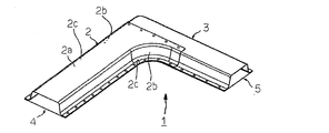
- the skeleton member 1 is assembled by joining the constituent members 2, 3, 4, and 5 by spot welding.
- the component member 2 has a substantially hat-shaped cross-sectional shape.
- the substantially hat-shaped cross-sectional shape has a top plate 2a, a pair of left and right vertical walls 2b, 2b, and flanges 2c, 2c connected to the vertical walls 2b, 2b.
- the top plate 2a has an inverted L-shaped outer shape in a plan view viewed from a direction orthogonal to the top plate 2a.
- constituent member having an L-shaped outer shape in contrast to the constituent member 2 shown in FIG.
- components having an L-shaped or inverted L-shaped outer shape in the plan view are collectively referred to as “L-shaped components”.
- the strength and rigidity of the skeleton member 1 are ensured by having L-shaped parts as components.
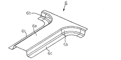
- FIG. 15 is an explanatory view showing an example of the T-shaped component 6.
- the top plate 6a of the T-shaped component 6 has a T-shaped outer shape in a plan view viewed from a direction orthogonal to the top plate 6a.
- a center pillar reinforcement is known as a T-shaped part 6.
- the T-shaped part 6 has a substantially hat-shaped cross-sectional shape, similar to the L-shaped part 2.
- the substantially hat-shaped transverse cross-sectional shape includes a top plate 6a, a pair of left and right vertical walls 6b and 6b, and a pair of left and right flanges 6c and 6c.
- a Y-type component (see FIG. 13 described later) is known as a modification of the T-type component 6.
- the top plate 6a of the Y-shaped component has a Y-shaped outer shape in the plan view.
- the L-shaped component 2, the T-shaped component 6, and the Y-shaped component are collectively referred to as “curved components”.
- Curved parts are usually manufactured by press working by drawing to prevent wrinkling.
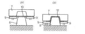
- FIG. 16 is an explanatory view showing an outline of press working by drawing, FIG. 16 (a) shows before the start of molding, and FIG. 16 (b) shows the time when molding is completed (molding bottom dead center).
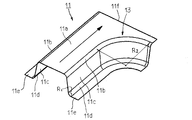
- FIG. 17 is an explanatory view showing an example of a press part 11 manufactured by press working by drawing
- FIG. 18 is an explanatory view showing a blank 10 which is a forming material of the press part 11, and FIG. It is explanatory drawing which shows the wrinkle holding
- the press part 11 shown in FIG. 17 is manufactured, for example, by press working by drawing through steps (i) to (iv) listed below.
- the blank holder 9 suppresses the blank 10 from excessively flowing into the mold in the press working by drawing. For this reason, generation
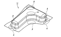
- FIG. 21 is an explanatory diagram showing an example of the occurrence of press defects (wrinkles and cracks) in the intermediate press part 12.
- a relatively low-strength steel sheet having excellent ductility has been used as a curved part blank 10 in order to prevent wrinkles and cracks in the intermediate press part 12. For this reason, in order to ensure the strength required for the curved part, the thickness of the blank 10 must be increased, and an increase in the weight of the curved part and an increase in manufacturing cost are inevitable.
- Patent Document 1 The present applicant previously disclosed a patented invention according to Patent Document 1 that can press a curved part with high yield by bending without causing wrinkles or cracks even when using a blank made of a high-tensile steel sheet having low ductility.
- the method according to the patented invention is also referred to as “free bending method”.
- FIG. 22 is an explanatory view partially showing an outline of the patented invention disclosed by Patent Document 1.
- FIG. 22 is an explanatory view partially showing an outline of the patented invention disclosed by Patent Document 1.
- Patent Document 1 manufactures a pressed part 11 by performing press working by bending a cold or warm on a blank.
- the pressed part 11 includes a top plate 11a, convex ridge lines 11b, 11b, vertical walls 11c, 11c, concave ridge lines 11d, 11d, and flanges 11e, 11e (for example, Hat-shaped cross-sectional shape).
- the top plate 11a extends in one direction (the direction indicated by the arrow in FIG. 17).
- the convex ridgelines 11b and 11b are respectively connected to both end portions in the width direction (direction orthogonal to one direction) of the top plate 11a.
- the vertical walls 11c and 11c are connected to the convex ridgelines 11b and 11b, respectively.
- the concave ridge lines 11d and 11d are connected to the vertical walls 11c and 11c, respectively.
- the flanges 11e and 11e are connected to the concave ridge lines 11d and 11d, respectively.
- a blank 18 is disposed between the die 15 and die pad 16 of the press molding machine 14 by bending and the punch 17.
- the portion of the blank 18 that is formed on the end portion 11f (the portion corresponding to the bottom of the inverted L shape) is curved while moving (sliding) in-plane on the portion of the die 15 that forms the top plate 11a.
- a vertical wall 11c, a concave ridge line 11d, and a flange 11e on the inner peripheral side of the portion 13 are formed.
- the blank 18 is pressed and the press part 11 which has the curved part 13 is manufactured, it will shape
- the amount of inflow that flows into the portion of the blank 18 that is formed on the vertical wall 11c increases.
- the wrinkle pressing area (cutting area) that is always provided in the blank 18 at the time of press working by normal drawing is not required. For this reason, the yield of the press part 11 improves.
- the free bending method is press working by bending.
- the ductility required for the blank 18 in the free bending method is smaller than the ductility required for the blank in press working by drawing. Therefore, it is possible to use a high-strength steel plate having relatively low ductility as the blank 18, the thickness of the blank 18 can be set small, and the weight of the vehicle can be reduced.
- the applicant of the present invention provides an invention in which a surplus portion having a specific shape is provided at the edge of a portion formed on the flange 11e on the inner peripheral side of the curved portion 13 in the development blank used in the free bending method. Disclosed.
- the top plate in the blank 18 is further improved while further improving the formability in the vicinity of the curved portion 13 by the free bending method and preventing cracking of the flange 11e on the inner peripheral side of the curved portion 13.
- An excessive inflow of the blank 18 from a portion molded into the blank 11 to a portion molded into the vertical wall 11c in the blank 18 can be suppressed, and cracking of the end of the top plate 11a can be prevented.
- the blank 18 is made of a super high strength steel plate having a tensile strength of 1180 MPa or more
- the height of the pressed part 11 is as high as 70 mm or more.
- the present invention was made in order to solve these novel problems possessed by the inventions disclosed in Patent Documents 1 and 2.
- the object of the present invention is to produce a curved part without causing cracks in the flange on the inner peripheral side of the curved portion even when the blank is pressed by a free bending method in the first case or the second case. It is to provide a manufacturing method and a manufacturing apparatus of a pressed part.
- the limit of the inflow amount is geometrically determined by the amount of change in the cross-sectional line length of the flange 11e before and after forming the cross section in the inflow direction. And the limit of this inflow amount becomes the forming limit in the free bending method.
- the inflow amount can be increased by forming a material inflow promoting portion such as a bead simultaneously with the press forming.
- the shape of the material inflow accelerating portion ensures a cross-sectional line length difference in the material inflow direction (the maximum principal strain direction of deformation of the portion formed on the flange 11e on the inner peripheral side of the curved portion 13 in the blank 18). By making it a shape that can be formed, the inflow amount can be increased, and thereby the forming limit in the free bending method can be increased.
- the present invention is as listed below.
- a top plate extending in one direction, a convex ridge line connected to an end of the top plate in a direction orthogonal to the one direction, a vertical wall connected to the convex ridge line, and a concave ridge line connected to the vertical wall; And having a cross-sectional shape constituted by the flange connected to the concave ridge line, and the convex ridge line, the vertical wall, and the concave ridge line are curved so that the outer shape of the top plate is viewed in a plane perpendicular to the top plate.
- a portion formed on a part of the top plate of the curved portion of the blank is pressed with a pressure of 1.0 MPa or more and less than 32.0 MPa by the die pad, or a gap between the die pad and the punch is formed. More than the thickness of the blank and 1.1 times or less the thickness of the blank, the die pad is brought close to or in contact with the portion formed on a part of the top plate of the curved portion in the blank, The die and the punch are brought close to each other in a state where a portion of the blank formed at the end portion in the one direction of the top plate is on the same plane as a portion of the blank formed on the top plate.
- the material inflow promoting portion Is a cross section in which a cross-sectional line length in a cross section parallel to a straight line in contact with the center position of the inner periphery of the bending portion increases as the distance from the flange on the inner peripheral side of the bending portion increases in a plan view orthogonal to the top plate.
- the blank is made of an ultra high strength steel plate having a tensile strength of 1180 MPa or more,
- the projection distance in the product height direction of the vertical wall, which is the height of the pressed part, is 70 mm or more,
- At least one of the radius of curvature of the concave ridge line of the pressed part is 10 mm or less in a side view, or the radius of curvature on the inner peripheral side of the curved portion in the pressed part is 100 mm or less in the plan view.
- the blank is made of a super high strength steel plate having a tensile strength of 1180 MPa or more,
- the projected distance in the product height direction of the vertical wall, which is the height of the pressed part, is 55 mm or more,
- Two or more of the curvature radius of the concave ridge line of the press part is 15 mm or less in a side view, or the curvature radius inside the curved portion in the press part is 140 mm or less in the plan view.
- the material inflow promoting portion is a convex bead that is convex toward the same side as the top plate of the press component, or a concave bead that is convex toward the opposite side of the top plate of the press component. 6.
- the material inflow promoting portion has an outer shape obtained by connecting an association point of the concave ridge line and the flange in the molded curved portion and an end portion of the blank at the start of molding.
- the cross-sectional shape includes a top plate extending in one direction, two convex ridge lines connected to both ends of the top plate in a direction orthogonal to the one direction, and the two convex ridge lines. 1 to 9 each having a hat-shaped cross-sectional shape including two vertical walls connected to each other, two concave ridge lines connected to the two vertical walls, and two flanges connected to the two concave ridge lines, respectively.
- the manufacturing method of the press part in any one of claim
- a die and a die pad, and a punch arranged to face the die and the die pad are provided, and a blank or a preformed blank arranged between the die and the die pad and the punch is pressed.
- a top plate extending in one direction, a convex ridge line connected to an end of the top plate in a direction orthogonal to the one direction, a vertical wall connected to the convex ridge line, and a concave ridge line connected to the vertical wall; And having a cross-sectional shape constituted by a flange connected to the concave ridge line, and the convex ridge line, the vertical wall, and the concave ridge line are curved so that the outer shape of the top plate is viewed in a plane perpendicular to the top plate.
- An apparatus for producing a pressed part having a curved portion of L type, T type or Y type The die pad presses a portion of the blank that is formed on a portion of the top plate of the top plate with a pressure of 1.0 MPa or more and less than 32.0 MPa, or the die pad is Close or in contact with a portion formed on a part of the top plate of the curved portion of the blank while keeping the gap not less than the plate thickness of the blank and not more than 1.1 times the plate thickness of the blank,
- the die and the punch are mutually in a state where a portion of the blank that is formed at an end portion in the one direction of the top plate is on the same plane as a portion of the blank that is formed on the top plate.
- the portion formed at the end of the blank is moved in-plane on the portion of the die where the top plate is formed, and the inner periphery of the curved portion is moved.
- the die and the punch are formed in the vicinity of a portion formed on the flange on the inner peripheral side of the curved portion of the pressed part (for example, only the flange, or the flange and the concave ridge line) by the pressing.
- An inflow promoting portion forming mechanism, and the material inflow promoting portion forming mechanism is a plan view orthogonal to the top plate, and the material inflow promoting portion in a cross section parallel to a straight line in contact with the central position of the inner periphery of the bending portion.
- the material inflow promoting portion is provided so that the cross-sectional line length of the portion increases with distance from the flange on the inner peripheral side of the curved portion apparatus.
- the blank is made of an ultra high strength steel plate having a tensile strength of 1180 MPa or more,
- the projection distance in the product height direction of the vertical wall, which is the height of the pressed part, is 70 mm or more,
- At least one of the radius of curvature of the concave ridge line of the pressed part is 10 mm or less in a side view, or the radius of curvature on the inner peripheral side of the curved portion in the pressed part is 100 mm or less in the plan view.
- the blank is made of an ultra-high strength steel plate having a tensile strength of 1180 MPa or more,
- the projected distance in the product height direction of the vertical wall, which is the height of the pressed part, is 55 mm or more,
- Two or more of the curvature radius of the concave ridge line of the press part is 15 mm or less in a side view, or the curvature radius inside the curved portion in the press part is 140 mm or less in the plan view.
- the manufacturing apparatus of the press part of Claim 11 which is satisfied.
- the material inflow promoting portion is a convex bead that is convex toward the same side as the top plate of the press component, or a concave bead that is convex toward the opposite side of the top plate of the press component. 16.
- the material inflow accelerating portion forming mechanism is obtained by connecting the material inflow accelerating portion by connecting the concave ridge line in the molded curved portion and the meeting point of the flange with the end of the blank at the start of molding. 19.
- the cross-sectional shape includes a top plate extending in one direction, two convex ridge lines connected to both ends of the top plate in a direction orthogonal to the one direction, and the two convex ridge lines. 11 to 19 each having a hat-shaped cross-sectional shape including two vertical walls connected to each other, two concave ridge lines connected to the two vertical walls, and two flanges connected to the two concave ridge lines, respectively.
- the manufacturing apparatus of the press parts in any one of claim
- the inflow amount of the material is increased as compared with the free bending method disclosed in Patent Documents 1 and 2.
- the molding limit can be increased, which makes it possible to manufacture a pressed part without causing cracks in the flange on the inner peripheral side of the curved part of the pressed part.
- FIG. 1 is an explanatory view showing a configuration example of a manufacturing apparatus according to the present invention.
- FIG. 2 is an explanatory view partially showing an example of a pressed part press-molded by the manufacturing apparatus according to the present invention.
- FIG. 3 is an explanatory diagram showing a positional relationship between the material inflow promoting portion forming mechanism and the concave ridge line forming portion and the blank in the manufacturing apparatus according to the present invention.
- FIG. 4 is an explanatory view showing a cross section corresponding to the AA cross section of FIG. 1 in a conventional punch not provided with a material inflow promoting portion forming mechanism.
- FIG. 1 is an explanatory view showing a configuration example of a manufacturing apparatus according to the present invention.
- FIG. 2 is an explanatory view partially showing an example of a pressed part press-molded by the manufacturing apparatus according to the present invention.
- FIG. 3 is an explanatory diagram showing a positional relationship between the material inflow promoting portion forming mechanism and the concave
- FIG. 5 is an explanatory diagram showing a positional relationship between a material inflow promoting portion forming mechanism and a concave ridge line forming portion and a blank and positions of B, C, and D cross sections in the manufacturing apparatus according to the present invention.
- FIG. 6 is a graph showing a cross-sectional line length difference with respect to a conventional punch at a flange forming portion of the punch in B, C, and D cross sections.
- FIG. 7 is an explanatory view showing an AA section of the punch provided with the material inflow promoting portion forming mechanism.
- FIG. 8 is an explanatory diagram showing the positional relationship between the material inflow promoting portion forming mechanism and the concave ridge line forming portion and the blank and the positions of the B, C, and D cross sections in the manufacturing apparatus according to the present invention.
- FIG. 9 is an explanatory view showing the reason why cracking at the a part of the blank is prevented by providing the die and punch with a material inflow promoting part forming mechanism constituted by a concave part and a convex part.
- 10 (a) to 10 (f) are explanatory views partially showing examples of shapes of convex portions or concave portions that are components of various material inflow promoting portion forming mechanisms provided in the punch.
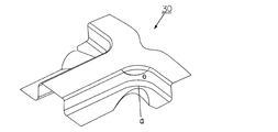
- FIG. 12 is an explanatory view showing an intermediate part of the T-shaped part (example of the present invention).
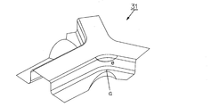
- FIG. 13 is an explanatory view showing an intermediate part of the Y-shaped part (example of the present invention).
- FIG. 14 is an explanatory diagram illustrating an example of a skeleton member.
- FIG. 15 is an explanatory diagram showing an example of a T-shaped component.
- FIG. 16 is an explanatory view showing an outline of press working by drawing, in which FIG. 16 (a) shows before the start of molding, and FIG. 16 (b) shows the time when molding is completed (molding bottom dead center).
- FIG. 16 is an explanatory view showing an outline of press working by drawing, in which FIG. 16 (a) shows before the start of molding, and FIG. 16 (b) shows the time when molding is completed (molding bottom dead center).
- FIG. 17 is an explanatory view showing an example of a press part manufactured by press working by drawing.
- FIG. 18 is an explanatory view showing a blank that is a forming material of a pressed part.
- FIG. 19 is an explanatory diagram showing a wrinkle holding region in a blank.
- FIG. 20 is an explanatory view showing an intermediate press part that has been subjected to press working.
- FIG. 21 is an explanatory diagram showing an example of a press defect occurrence state in the intermediate press part.
- FIG. 22 is an explanatory view partially showing an outline of the patented invention disclosed by Patent Document 1. In FIG.
- the press part 11 manufactured according to the present invention is an L-shaped part having a reverse L-shaped outer shape in a plan view orthogonal to the top board 11a is taken as an example.
- the manufacturing object of the present invention is not limited to L-shaped parts, but includes other curved parts (T-shaped parts, Y-shaped parts).
- the press part 11 and the intermediate part 11-1 are the top plate 11a, the two convex ridge lines 11b, 11b, the two vertical walls 11c, 11c, the two concave ridge lines 11d, 11d, and the two flanges 11e. , 11e, and a hat-shaped cross-sectional shape.
- the manufacturing object of the present invention is not limited to the press part 11 and the intermediate part 11-1 having a hat-shaped cross section, and the intermediate part 11- of the press part having a cross section shown in FIG. 2 and 11-3 are also included.
- FIG. 1 is an explanatory diagram showing a configuration example of a manufacturing apparatus 20 according to the present invention.
- FIG. 2 is an explanatory view partially showing an example of the intermediate part 11-1 of the press part 11 press-formed by the manufacturing apparatus 20.
- the manufacturing apparatus 20 is a press forming apparatus by bending using a free bending method.
- the manufacturing apparatus 20 includes a die 21, a die pad 22, and a punch 23.
- the punch 23 is disposed to face the die 21 and the die pad 22.
- the die pad 22 can move up and down together with the die 21 and can press a part of the blank 24.
- the manufacturing apparatus 20 includes a blank (development blank) 24 disposed between the die 21 and the die pad 22 and the punch 23, or a blank that has been preformed as a light processing (for example, embossing) (not shown). 2), the intermediate part 11-1 of the pressed part 11 having the outer shape shown in FIG. 2 is manufactured.
- the plate thickness of the blank 24 is preferably 0.6 to 2.8 mm, more preferably 0.8 to 2.8 mm, and still more preferably 1.0 to 2.8 mm.
- the press part 11 or its intermediate part 11-1 has a hat-shaped cross-sectional shape.
- the hat-shaped cross-sectional shape includes a top plate 11a, two convex ridge lines 11b and 11b, two vertical walls 11c and 11c, two concave ridge lines 11d and 11d, and two flanges 11e and 11e. It is.
- the press part 11 or its intermediate part 11-1 has a curved portion 13.
- the bending portion 13 is bent so that the outer shape of the top plate 11a is an inverted L shape in a plan view orthogonal to the top plate 11a.
- the top plate 11a extends in one direction (the arrow direction in FIGS. 2 and 17).
- the two convex ridgelines 11b and 11b are connected to both ends of a direction orthogonal to one direction of the top plate 11a (that is, the width direction of the top plate 11a).
- the two vertical walls 11c and 11c are connected to the two convex ridgelines 11b and 11b, respectively.
- the two concave ridge lines 11d and 11d are connected to the two vertical walls 11c and 11c, respectively.
- the two flanges 11e and 11e are connected to the two concave ridge lines 11d and 11d, respectively.
- the manufacturing apparatus 20 In the first case: the blank 24 is made of an ultra-high tensile steel plate having a tensile strength of 1180 MPa or more, and the projection distance in the product height direction of the vertical wall 11c, which is the height of the press part 11 or its intermediate part 11-1, is 70 mm.
- the pressed parts 11 or the radius of curvature R 1 of the ⁇ line 11d of the intermediate part 11-1 is 10mm or less in a side view, or, the curved portion 13 of the press parts 11 or the middle part 11-1
- the radius of curvature R 2 of the inner circumferential side of satisfies one or more of that is less than 100mm in plan view, or a second case: the blank 18 that has the above tensile strength 1180MPa ultra high-tensile steel plate
- the height of the pressed part 11 or its intermediate part 11-1 (projection distance of the vertical wall 11c in the product height direction) is 55 mm or more, Is that the radius of curvature R 1 of ⁇ line 11d of the intermediate part 11-1 is 15mm or less in a side view, or the radius of curvature R 2 inside of the curved portion 13 of the press parts 11 or the middle part 11-1 It is preferably used when at least two of 140 mm or less in a plan view are satisfied.
- the resulting pressed part 11 or the inner flange 11e of the curved part 13 of the intermediate part 11-1 is cracked. This is because the significance of using the manufacturing apparatus 20 is recognized.
- the die pad 22 presses a portion of the blank 24 that is formed on a part of the top plate 11a of the curved portion 13 of the press part 11 with a pressure of 1.0 MPa or more and less than 32.0 MPa,
- the distance of the gap is kept at the plate thickness of the blank 24 ⁇ (1.0 to 1.1), and is close to or in contact with the above portion of the blank 24.
- the die pad 22 manufactures the intermediate part 11-1 of the pressed part 11 by performing the press working described below while suppressing the out-of-plane deformation in the above portion of the blank 24.
- the die 24 is formed in a state where the portion of the blank 24 that is formed on the end portion 11f in one direction of the top plate 11a is on the same plane as the portion of the blank 24 that is formed on the top plate 11a. 21 and the punch 23 are moved relative to each other in a direction approaching each other.
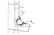
- FIG. 3 is an explanatory diagram showing a positional relationship between the material inflow promoting portion forming mechanism 25 and the concave ridge line forming portion 23 b and the blank 24 in the manufacturing apparatus 20.
- the manufacturing apparatus 20 includes a die 21 and a punch of the manufacturing apparatus 20 as shown in FIGS. 23, a concave portion 21a and a convex portion 23a for providing the material inflow promoting portion 19 in the blank 24 are provided as the material inflow promoting portion forming mechanism 25, respectively.
- the material inflow promoting portion forming mechanism 25 includes a concave portion 21 a provided in the die 21 and a convex portion 23 a provided in the punch 23.
- the manufacturing apparatus 20 is formed on the flange 11e on the inner peripheral side of the curved portion 13 of the intermediate part 11-1 in the blank 24 by the material inflow promoting portion forming mechanism 25 during the press working.
- the material inflow promoting portion 19 is provided in the vicinity of the portion (for example, only the flange or the flange and the concave ridge line).
- the material inflow promoting portion forming mechanism 25 provides the material inflow promoting portion 19 in an area outside the area (hatching area in FIG. 3) formed in the press part 11 in the blank 24. It is desirable. As a result, the outer edge of the flange 11e of the intermediate part 11-1 is cut off as a trim line, so that no trace of the material inflow promoting portion 19 can be left in the pressed part 11.
- the material inflow promoting portion 19 When the trace of the material inflow promoting portion 19 is allowed to remain in the pressed part 11, the material inflow promoting portion 19 is applied to the area (the hatched area in FIG. 3) in the blank 24 where the pressed part 11 is formed. , May be provided.
- FIG. 4 is an explanatory diagram showing a cross section corresponding to the AA cross section of FIG. 1 in a conventional punch 23-1 in which the material inflow promoting portion forming mechanism 25 is not provided.
- FIG. 5 is an explanatory diagram showing the positional relationship between the material inflow promoting portion forming mechanism 25 and the concave ridge line forming portion 23b and the blank 24 in the manufacturing apparatus 20, and the positions of the B, C, and D cross sections.
- FIG. 6 is a graph showing the cross-sectional line length difference (inflow amount) with respect to the conventional punch at the flange forming portion of the punch 23 in the B, C, and D cross sections.
- the left side shows the case of the conventional method
- the right side shows the case of the method of the present invention. 6 shows the shape of the blank 24 in the B, C, and D cross sections.
- FIG. 7 is an explanatory view showing an AA cross section of the punch 23 provided with the material inflow promoting portion forming mechanism 25.
- the material inflow promoting portion 19 is provided in the intermediate part 11-1 by pressing by providing the material inflow promoting portion forming mechanism 25 including the concave portion 21a and the convex portion 23a.
- the 5, 6 are cross sections in the material inflow direction parallel to a straight line in contact with the center position (a portion) of the inner periphery of the bending portion 13 in a plan view orthogonal to the top plate 11a.
- the B, C, and D cross sections are cross sections in the maximum principal strain direction of deformation in the portion formed on the flange 11e on the inner peripheral side of the curved portion 13.
- the material inflow promoting portion 19 is a cross sectional line in the B, C, and D cross sections. The length is provided so that it gradually increases as the distance from the flange 11e on the inner peripheral side of the curved portion 13 increases.
- the cross-sectional shape of the material inflow promoting portion 19 is not limited to a shape that monotonously increases as the distance from the inner flange 11e of the curved portion 13 of the intermediate part 11-1 is increased. May be included.
- the material inflow promoting portion forming mechanism 25 in the method of the present invention has a flange of the punch 23 in the B, C, and D cross sections as compared with the conventional method in which the material inflow promoting portion forming mechanism 25 is not provided.
- the cross-sectional line length difference (inflow amount) in the forming portion with respect to the conventional punch increases, and the cross-sectional line length difference (inflow amount) in the C section increases more than the cross-sectional line length difference (inflow amount) in the B cross section.
- the cross-sectional line length difference (inflow amount) in the D section is set to be larger than the cross-section line length difference (inflow amount) in the C section.
- the material inflow promoting portion forming mechanism 25 having a shape that increases the cross-sectional line length difference (inflow amount) of each of the B, C, and D cross sections is provided on the die 21 as the concave portion 21a and as the convex portion 23a. It is provided on the punch 23.
- the material inflow promoting portion 19 has an outer shape obtained by connecting the meeting point of the concave ridge line 11 d and the flange 11 e in the molded curved portion 13 and the end 24 a of the blank 24 at the start of molding. It is exemplified that the protrusion is provided.
- FIG. 8 is an explanatory diagram showing the positional relationship between the material inflow promoting portion forming mechanism 25 and the concave ridge line forming portion 23b and the blank 24 in the manufacturing apparatus 20 and the positions of the B, C, and D cross sections.
- the difference in change in the amount of inflow of the material by the material inflow promoting portion forming mechanism 25 is separated from the A section of the blank 24 from the B cross section, the C cross section, and the D cross section as shown by a thick arrow in FIG. As it increases, it increases.
- the crack of the a part of the blank 24 shown in FIG. 4 is caused by locally generating a tension in the circumferential direction that exceeds the breaking strength of the blank 24. For this reason, if the change of the cross-sectional line length difference is given to the a part, the crack of the a part is more likely to occur. Therefore, it is not necessary to provide a change in the cross-sectional line length difference in the part a. Moreover, what is necessary is just to let the area
- FIG. 9 is an explanatory diagram showing the reason why cracking at a part of the blank 24 is prevented by providing the die 21 and the punch 23 with the material inflow promoting part forming mechanism 25 constituted by the concave part 21a and the convex part 23a. It is.
- the crack in the a part of the blank 24 is caused by the high tension F in the circumferential direction of the concave ridge line 11d located in the upper part of the a part in the blank 23.
- the inflow amount of the blank 24 outside the portion a is increased by providing the material inflow promoting portion forming mechanism 25 to the die 21 and the punch 23 and performing press working.
- the inflow amount of the blank 24 from the periphery of the part a increases, the inflow amount of the blank 24 to the part a increases. That is, the material inflow promoting portion forming mechanism 25 increases the amount of inflow of the blank 24 into the portion of the blank 24 that is molded into the curved portion 13. Although the main stress direction of the deformation of the portion formed in the curved portion 13 in the blank 24 does not change greatly, the amount of deformation is reduced.
- the inflow amount of the blank 24 to the portion of the blank 24 that is formed on the flange 11e on the inner peripheral side of the curved portion 13 of the press part 11 is indicated by an arrow in FIG.
- it increases compared with the conventional construction method which does not provide the material inflow promotion part formation mechanism 25.
- a concave portion 23c that protrudes toward the side opposite to the top plate 11a of the press part 11 may be used.
- the die 21 is provided with a convex portion corresponding to the concave portion 23c.
- a convex portion 23a may be provided in a region where the blank 24 exists and contacts.
- the convex portion 23 a that is the material inflow promoting portion 19 is replaced with the blank 24. May be provided across the region (the hatched region in FIG. 3) formed in the pressed part 11.
- two or more independent convex portions 23 a may be provided as components of the material inflow promoting portion forming mechanism 25.
- the convex portion 23 a may be provided in a step shape in a direction parallel to the thickness direction of the blank 12.
- the material inflow promoting portion forming mechanism 25 is such that the portion of the blank 24 that is formed on the end portion 11f of the intermediate part 11-1 is the inner peripheral side of the curved portion 13 of the intermediate part 11-1.
- One or more material inflow promoting portions 19 that increase the amount of inflow flowing into the portion formed in the flange 11e are provided.
- 11 (a) and 11 (b) are explanatory views showing intermediate parts 11-2 and 11-3 of other press parts manufactured according to the present invention.
- the intermediate part 11-1 of the pressed part 11 is manufactured by a free bending method using the manufacturing apparatus 20.
- the pressed part 11 to be manufactured by the present invention satisfies the first case or the second case. This is because the pressed part 11 that satisfies the first case or the second case is cracked at the portion a of the blank 24 in the conventional free bending method.
- a portion (hatching portion 18 a in FIG. 20) formed on a part of the top plate 11 a of the curved portion 13 of the pressed part 11 is pressed by the die pad 22 with a pressure of 1.0 MPa or more and less than 32.0 MPa. While pressing or maintaining the gap distance between the die pad 22 and the punch 23 at the thickness of the blank 24 ⁇ (1.0 to 1.1), the top plate of the curved portion 13 of the press part 11 in the blank 24 The die pad 22 is brought close to or in contact with a portion (a hatched portion 18a in FIG. 20) formed into a part of 11a.
- the intermediate part 11-1 of the press part 11 is manufactured by performing the press working described below while suppressing the out-of-plane deformation of the part formed on a part of the top plate 11a.
- the die 24 is formed in a state where the portion of the blank 24 that is formed on the end portion 11f in one direction of the top plate 11a is on the same plane as the portion of the blank 24 that is formed on the top plate 11a. 21 and the punch 23 are moved relative to each other in a direction approaching each other.
- the material inflow promoting portion forming mechanism 25 provided in the die 21 and the punch 23 is near the portion of the blank 24 that is formed on the flange 11e on the inner peripheral side of the curved portion 13 of the intermediate part 11-1.
- at least one material inflow promoting portion 19 is provided.
- the inflow amount of the blank 24 to the portion of the blank 24 that is formed on the flange 11 e on the inner peripheral side of the curved portion 13 of the intermediate part 11-1 is increased.
- tensile_strength F to the circumferential direction of the concave ridgeline 11d located in the upper part of a part in the blank 24 can be reduced, and, thereby, the crack in the a part of the blank 24 is prevented.
- the pressed part 11 is the final product as it is.
- the intermediate part 11-1 has an unnecessary part
- the unnecessary part including the material inflow promoting part 19 is cut (trimmed) using the outer edge part of the flange 11e as a trim line, so that the pressed part 11 is obtained.
- the maximum plate thickness reduction rate at the intersection a portion of the concave ridge line 11d and the flange 11e at the center position in the circumferential direction of the curved portion 13 was analyzed by a finite element method using a computer.
- the specifications of the analyzed intermediate part 11-1 and the pressed part are as listed below. ⁇ Tensile strength of blanks 24 and 18, plate thickness: 1180 MPa or more, 1.6 mm ⁇ Height of intermediate part 11-1, press part (projection distance in vertical direction of product of vertical wall 11c): 60mm -Curvature radius R 1 of the intermediate part 11-1, the concave ridge line 11d of the pressed part: 20 mm in side view And intermediate parts 11-1, curvature inside of the curved portion 13 of the press parts radius R 2: 100 mm in a plan view
- calculation is performed by a dynamic explicit method using a finite element method, and it is determined that there is no crack at the meeting point when the maximum sheet thickness reduction rate is 8% or less, and more than 13% is cracked at the meeting point. It was determined that there was.
- the flange 11e on the inner peripheral side of the bending portion 13 is not cracked, and the L-shaped component 11-1 can be manufactured.
- the maximum plate thickness reduction rate at the intersection a portion of the concave ridge line 11d and the flange 11e at the center position in the circumferential direction of the curved portion 13 was analyzed by a finite element method using a computer.
- Table 1 summarizes the specifications and results of the analyzed intermediate part 11-1 and pressed parts.
- calculation is performed by a dynamic explicit method using a finite element method, and it is determined that the blank 24 having a tensile strength of 980 MPa has a maximum sheet thickness reduction rate of 15% or more and that there is no crack at the meeting point a.
- the maximum thickness reduction rate 10% or more was free from cracks at the above-mentioned meeting points.
- the flange 11e on the inner peripheral side of the curved portion 13 is cracked.
- the L-shaped part 11-1 can be manufactured without being generated.
- Table 2 summarizes the specifications and results of the analyzed intermediate parts 30 and 31.
- the opening angle in Table 2 means the angle ⁇ in FIGS.
- the flange 11e on the inner peripheral side of the curved portion 13 is cracked.
- the intermediate part 30 of the T-type part or the intermediate part 31 of the Y-type part can be manufactured without being generated.
Landscapes
- Engineering & Computer Science (AREA)
- Mechanical Engineering (AREA)
- Shaping Metal By Deep-Drawing, Or The Like (AREA)
- Mounting, Exchange, And Manufacturing Of Dies (AREA)
Abstract
Description
(iv)中間プレス部品12の周囲のシワ押さえ領域10a(不要部分である切除領域)を切除(トリム)することにより、図17に示すプレス部品11とする。
(i)ダイパッド16により1.0MPa以上かつ32.0MPa未満の加圧力で加圧すること、または(ii)ダイパッド16およびパンチ17の隙間の距離が{ブランク18の板厚×(1.0~1.1)}を満足するようにダイパッド16を近接または接触させること
により、天板11aに成形される部分の一部18aにおける面外変形を抑制しながら、以下に説明するプレス加工を行うことによって、プレス部品11を製造する。
(a)ブランク18が引張強度1180MPa以上の超高張力鋼板からなること、
(b)プレス部品11の高さ(縦壁11cの製品高さ方向への投影距離)が70mm以上と高いこと、
(c)プレス部品11の凹稜線11dの曲率半径R1が側面視で10mm以下と小さいこと、または
(d)プレス部品11における湾曲部13の曲率半径R2が平面視で100mm以下と小さいこと
のうちの少なくとも一つを満足する第1の場合、または
(e)ブランク18が引張強度1180MPa以上の超高張力鋼板からなること、
(f)プレス部品11の高さ(縦壁11cの製品高さ方向への投影距離)が55mm以上であること、
(g)プレス部品11の凹稜線11dの曲率半径R1が側面視で15mm以下であること、または
(e)プレス部品11における湾曲部13の内側の曲率半径R2が平面視で140mm以下であること
のうちの少なくとも二つ以上を満足する第2の場合
が挙げられる。第1の場合または第2の場合には、自由曲げ工法を用いても、湾曲部13の内周側のフランジ11eに割れが発生する。
一の方向へ延びて存在する天板と、該天板における前記一の方向と直交する方向の端部につながる凸稜線と、該凸稜線につながる縦壁と、該縦壁につながる凹稜線と、該凹稜線につながるフランジとにより構成される横断面形状を有するとともに、前記凸稜線、前記縦壁および前記凹稜線が湾曲することにより前記天板の外形を該天板に直交する平面視でL型、T型またはY型とする湾曲部を有するプレス部品を製造する際に、
前記ブランクにおける前記湾曲部の前記天板の一部に成形される部分を、前記ダイパッドにより1.0MPa以上かつ32.0MPa未満の加圧力で加圧し、あるいは、前記ダイパッドと前記パンチとの隙間を前記ブランクの板厚以上かつ前記ブランクの板厚の1.1倍以下に保って前記ブランクにおける前記湾曲部の前記天板の一部に成形される部分に前記ダイパッドを近接または接触させ、
前記ブランクにおける、前記天板の前記一の方向の端部に成形される部分が前記ブランクにおける前記天板に成形される部分と同一平面上に存在する状態で、前記ダイおよび前記パンチを互いに接近する方向へ相対的に移動させることによって、前記ブランクにおける前記天板の一の方向の端部に成形される部分を、前記ダイにおける前記天板を成形する部分の上で面内移動(スライド)させながら、前記湾曲部の内周側の前記縦壁、前記凹稜線および前記フランジを成形すること
によって前記プレス部品を製造する方法において、
前記プレス加工により、前記ブランクにおける、前記プレス部品の前記湾曲部の内周側のフランジに成形される部分の近傍(例えばフランジのみ、あるいはフランジおよび凹稜線)に、前記ブランクにおける前記端部に成形される部分が前記ブランクにおける前記湾曲部の内周側のフランジに成形される部分へ流入する流入量を増加する材料流入促進部を、一つまたは二つ以上設けること、および
該材料流入促進部は、前記天板に直交する平面視で、前記湾曲部の内周の中央位置に接する直線に平行な断面における断面線長が前記湾曲部の内周側のフランジから離れるに伴って増加する断面形状を有する、プレス部品の製造方法。
前記プレス部品の高さである前記縦壁の製品高さ方向への投影距離が70mm以上であること、
前記プレス部品の前記凹稜線の曲率半径が側面視で10mm以下であること、または
前記プレス部品における前記湾曲部の内周側の曲率半径が前記平面視で100mm以下であること
のうちの少なくとも一つを満足する、1項に記載のプレス部品の製造方法。
前記プレス部品の高さである前記縦壁の製品高さ方向への投影距離が55mm以上であること、
前記プレス部品の前記凹稜線の曲率半径が側面視で15mm以下であること、または
前記プレス部品における前記湾曲部の内側の曲率半径が前記平面視で140mm以下であること
のうちの二つ以上を満足する、1項に記載のプレス部品の製造方法。
一の方向へ延びて存在する天板と、該天板における前記一の方向と直交する方向の端部につながる凸稜線と、該凸稜線につながる縦壁と、該縦壁につながる凹稜線と、該凹稜線につながるフランジとにより構成される横断面形状を有するとともに、前記凸稜線、前記縦壁および前記凹稜線が湾曲することにより前記天板の外形を、該天板に直交する平面視でL型,T型またはY型とする湾曲部を有するプレス部品を製造する装置であって、
前記ダイパッドは、前記ブランクにおける前記湾曲部の前記天板の一部に成形される部分を1.0MPa以上かつ32.0MPa未満の加圧力で加圧すること、あるいは、前記ダイパッドは、前記パンチとの隙間を前記ブランクの板厚以上かつ前記ブランクの板厚の1.1倍以下に保って前記ブランクにおける前記湾曲部の前記天板の一部に成形される部分に、近接または接触すること、
前記ダイおよび前記パンチは、前記ブランクにおける、前記天板の前記一の方向の端部に成形される部分が前記ブランクにおける前記天板に成形される部分と同一平面上に存在する状態で、互いに接近する方向へ相対的に移動することによって、前記ブランクにおける前記端部に成形される部分を、前記ダイにおける前記天板を成形する部分の上で面内移動させながら、前記湾曲部の内周側の前記縦壁、前記凹稜線および前記フランジを成形することによって前記プレス部品を製造する装置において、
前記ダイおよび前記パンチは、前記プレス加工により、前記ブランクにおける、前記プレス部品の前記湾曲部の内周側のフランジに成形される部分の近傍(例えばフランジのみ、あるいはフランジおよび凹稜線)に、前記ブランクにおける前記端部に成形される部分が、前記ブランクにおける、前記湾曲部の内周側のフランジに成形される部分へ流入する量を増加する材料流入促進部を一つまたは二つ以上設ける材料流入促進部形成機構を備えること、および
前記材料流入促進部形成機構は、前記天板に直交する平面視で、前記湾曲部の内周の中央位置に接する直線と平行な断面における前記材料流入促進部の断面線長が、前記湾曲部の内周側のフランジから離れるに伴って増加するように、前記材料流入促進部を設ける、プレス部品の製造装置。
前記プレス部品の高さである前記縦壁の製品高さ方向への投影距離が70mm以上であること、
前記プレス部品の前記凹稜線の曲率半径が側面視で10mm以下であること、または
前記プレス部品における前記湾曲部の内周側の曲率半径が前記平面視で100mm以下であること
のうちの少なくとも一つを満足する、11項に記載のプレス部品の製造装置。
前記プレス部品の高さである前記縦壁の製品高さ方向への投影距離が55mm以上であること、
前記プレス部品の前記凹稜線の曲率半径が側面視で15mm以下であること、または
前記プレス部品における前記湾曲部の内側の曲率半径が前記平面視で140mm以下であること
のうちの二つ以上を満足する、11項に記載のプレス部品の製造装置。
11a 天板
11e フランジ
11f 端部
13 湾曲部
19 材料流入促進部
20 プレス成形装置
21 ダイ
22 ダイパッド
23 パンチ
24 ブランク
25 材料流入促進部形成機構
図1は、本発明に係る製造装置20の構成例を示す説明図である。図2は、製造装置20によりプレス成形されたプレス部品11の中間部品11-1の一例を部分的に示す説明図である。
第1の場合:ブランク24が引張強度1180MPa以上の超高張力鋼板からなること、プレス部品11またはその中間部品11-1の高さである縦壁11cの製品高さ方向への投影距離が70mm以上であること、プレス部品11またはその中間部品11-1の凹稜線11dの曲率半径R1が側面視で10mm以下であること、または、プレス部品11またはその中間部品11-1における湾曲部13の内周側の曲率半径R2が平面視で100mm以下であることのうちの一つ以上を満足する場合、または
第2の場合:ブランク18が引張強度1180MPa以上の超高張力鋼板からなること、プレス部品11またはその中間部品11-1の高さ(縦壁11cの製品高さ方向への投影距離)が55mm以上であること、プレス部品11またはその中間部品11-1の凹稜線11dの曲率半径R1が側面視で15mm以下であること、または、プレス部品11またはその中間部品11-1における湾曲部13の内側の曲率半径R2が平面視で140mm以下であることのうちの少なくとも二つ以上を満足する場合
に好適に用いられる。
材料流入促進部19は、B,C,D断面における断面線長が湾曲部13の内周側のフランジ11eから離れるに伴って緩やかに増加するように、設けられる。
この製造方法では、基本的に、製造装置20を用いて自由曲げ工法によりプレス部品11の中間部品11-1を製造する。
・ブランク24,18の引張強度,板厚:1180MPa以上,1.6mm
・中間部品11-1,プレス部品の高さ(縦壁11cの製品高さ方向への投影距離):60mm
・中間部品11-1,プレス部品の凹稜線11dの曲率半径R1:側面視で20mm
・中間部品11-1,プレス部品の湾曲部13の内側の曲率半径R2:平面視で100mm
この解析では、有限要素法を用いた動的陽解法で計算しており、最大板厚減少率8%以下を上記会合点での割れがないと判定し、13%超を上記会合点で割れがあると判定した。


Claims (20)
- 曲げ成形によるプレス成形装置を構成するダイおよびダイパッドと、該ダイおよびダイパッドに対向して配置されるパンチとの間に配置されたブランクまたは予成形されたブランクにプレス加工を行うことによって、
一の方向へ延びて存在する天板と、該天板における前記一の方向と直交する方向の端部につながる凸稜線と、該凸稜線につながる縦壁と、該縦壁につながる凹稜線と、該凹稜線につながるフランジとにより構成される横断面形状を有するとともに、前記凸稜線、前記縦壁および前記凹稜線が湾曲することにより前記天板の外形を該天板に直交する平面視でL型、T型またはY型とする湾曲部を有するプレス部品を製造する際に、
前記ブランクにおける前記湾曲部の前記天板の一部に成形される部分を、前記ダイパッドにより弱く加圧し、あるいは、前記ダイパッドと前記パンチとの隙間を前記ブランクの板厚以上かつ前記ブランクの板厚の1.1倍以下に保って前記ブランクにおける前記湾曲部の前記天板の一部に成形される部分に前記ダイパッドを近接または接触させ、
前記ブランクにおける、前記天板の前記一の方向の端部に成形される部分が前記ブランクにおける前記天板に成形される部分と同一平面上に存在する状態で、前記ダイおよび前記パンチを互いに接近する方向へ相対的に移動させることによって、前記ブランクにおける前記天板の一の方向の端部に成形される部分を、前記ダイにおける前記天板を成形する部分の上で面内移動させながら、前記湾曲部の内周側の前記縦壁、前記凹稜線および前記フランジを成形すること
によって前記プレス部品を製造する方法において、
前記プレス加工により、前記ブランクにおける、前記プレス部品の前記湾曲部の内周側のフランジに成形される部分の近傍に、前記ブランクにおける前記端部に成形される部分が前記ブランクにおける前記湾曲部の内周側のフランジに成形される部分へ流入する流入量を増加する材料流入促進部を、一つまたは二つ以上設けること、および
該材料流入促進部は、前記天板に直交する平面視で、前記湾曲部の内周の中央位置に接する直線に平行な断面における断面線長が前記湾曲部の内周側のフランジから離れるに伴って増加する断面形状を有する、プレス部品の製造方法。 - 前記ブランクが引張強度1180MPa以上の超高張力鋼板からなること、
前記プレス部品の高さである前記縦壁の製品高さ方向への投影距離が70mm以上であること、
前記プレス部品の前記凹稜線の曲率半径が側面視で10mm以下であること、または
前記プレス部品における前記湾曲部の内周側の曲率半径が前記平面視で100mm以下であること
のうちの少なくとも一つを満足する、請求項1に記載のプレス部品の製造方法。 - 前記ブランクが引張強度1180MPa以上の超高張力鋼板からなること、
前記プレス部品の高さである前記縦壁の製品高さ方向への投影距離が55mm以上であること、
前記プレス部品の前記凹稜線の曲率半径が側面視で15mm以下であること、または
前記プレス部品における前記湾曲部の内側の曲率半径が前記平面視で140mm以下であること
のうちの二つ以上を満足する、請求項1に記載のプレス部品の製造方法。 - 前記材料流入促進部は、前記ブランクにおける、前記プレス部品に成形される領域の外側の領域に設けられる、請求項1~3のいずれかに記載のプレス部品の製造方法。
- 前記断面形状は、前記断面線長が部分的に一定である場合を含む、請求項1~4のいずれかに記載のプレス部品の製造方法。
- 前記材料流入促進部は、前記プレス部品の前記天板と同じ側へ向けて凸となる凸ビード、または前記プレス部品の前記天板と反対側へ向けて凸となる凹ビードである、請求項1~5のいずれかに記載のプレス部品の製造方法。
- 前記材料流入促進部は、少なくとも、前記ブランクが存在する領域に設けられる、請求項1~6のいずれかに記載のプレス部品の製造方法。
- 前記材料流入促進部は、前記ブランクの板厚方向と平行な方向へ段差状に設けられる、請求項1~7のいずれかに記載のプレス部品の製造方法。
- 前記材料流入促進部は、成形された前記湾曲部における前記凹稜線および前記フランジの会合点と成形開始時における前記ブランクの端部とを結んで得られる外形を有する、請求項1~8のいずれかに記載のプレス部品の製造方法。
- 前記横断面形状は、一の方向へ延びて存在する天板と、該天板における前記一の方向と直交する方向の両端部につながる二つの凸稜線と、該二つの凸稜線にそれぞれつながる二つの縦壁と、該二つの縦壁にそれぞれつながる二つの凹稜線と、該二つの凹稜線にそれぞれつながる二つのフランジとにより構成されるハット型の横断面形状である、請求項1~9のいずれかに記載のプレス部品の製造方法。
- ダイおよびダイパッドと、該ダイおよびダイパッドに対向して配置されるパンチとを備え、前記ダイおよびダイパッドと前記パンチとの間に配置されたブランクまたは予成形されたブランクにプレス加工を行うことによって、
一の方向へ延びて存在する天板と、該天板における前記一の方向と直交する方向の端部につながる凸稜線と、該凸稜線につながる縦壁と、該縦壁につながる凹稜線と、該凹稜線につながるフランジとにより構成される横断面形状を有するとともに、前記凸稜線、前記縦壁および前記凹稜線が湾曲することにより前記天板の外形を、該天板に直交する平面視でL型,T型またはY型とする湾曲部を有するプレス部品を製造する装置であって、
前記ダイパッドは、前記ブランクにおける前記湾曲部の前記天板の一部に成形される部分を弱く加圧すること、あるいは、前記ダイパッドは、前記パンチとの隙間を前記ブランクの板厚以上かつ前記ブランクの板厚の1.1倍以下に保って前記ブランクにおける前記湾曲部の前記天板の一部に成形される部分に、近接または接触すること、
前記ダイおよび前記パンチは、前記ブランクにおける、前記天板の前記一の方向の端部に成形される部分が前記ブランクにおける前記天板に成形される部分と同一平面上に存在する状態で、互いに接近する方向へ相対的に移動することによって、前記ブランクにおける前記端部に成形される部分を、前記ダイにおける前記天板を成形する部分の上で面内移動させながら、前記湾曲部の内周側の前記縦壁、前記凹稜線および前記フランジを成形すること
によって前記プレス部品を製造する装置において、
前記ダイおよび前記パンチは、前記プレス加工により、前記ブランクにおける、前記プレス部品の前記湾曲部の内周側のフランジに成形される部分の近傍に、前記ブランクにおける前記端部に成形される部分が、前記ブランクにおける、前記湾曲部の内周側のフランジに成形される部分へ流入する量を増加する材料流入促進部を一つまたは二つ以上設ける材料流入促進部形成機構を備えること、および
前記材料流入促進部形成機構は、前記天板に直交する平面視で、前記湾曲部の内周の中央位置に接する直線と平行な断面における前記材料流入促進部の断面線長が、前記湾曲部の内周側のフランジから離れるに伴って増加するように、前記材料流入促進部を設ける、プレス部品の製造装置。 - 前記ブランクが引張強度1180MPa以上の超高張力鋼板からなること、
前記プレス部品の高さである前記縦壁の製品高さ方向への投影距離が70mm以上であること、
前記プレス部品の前記凹稜線の曲率半径が側面視で10mm以下であること、または
前記プレス部品における前記湾曲部の内周側の曲率半径が前記平面視で100mm以下であること
のうちの少なくとも一つを満足する、請求項11に記載のプレス部品の製造装置。 - 前記ブランクが引張強度1180MPa以上の超高張力鋼板からなること、
前記プレス部品の高さである前記縦壁の製品高さ方向への投影距離が55mm以上であること、
前記プレス部品の前記凹稜線の曲率半径が側面視で15mm以下であること、または
前記プレス部品における前記湾曲部の内側の曲率半径が前記平面視で140mm以下であること
のうちの二つ以上を満足する、請求項11に記載のプレス部品の製造装置。 - 前記材料流入促進部形成機構は、前記材料流入促進部を、前記ブランクにおける、前記プレス部品に成形される領域の外側の領域に、設ける、請求項11~13のいずれかに記載のプレス部品の製造装置。
- 前記断面形状は、前記断面線長が部分的に一定である場合を含む、請求項11~14のいずれかに記載のプレス部品の製造装置。
- 前記材料流入促進部は、前記プレス部品の前記天板と同じ側へ向けて凸となる凸ビード、または前記プレス部品の前記天板と反対側へ向けて凸となる凹ビードである、請求項11~15のいずれかに記載のプレス部品の製造装置。
- 前記材料流入促進部形成機構は、前記材料流入促進部を、少なくとも、前記ブランクが存在する領域に設ける、請求項11~16のいずれかに記載のプレス部品の製造装置。
- 前記材料流入促進部形成機構は、前記材料流入促進部を、前記ブランクの板厚方向と平行な方向へ段差状に設ける、請求項11~17のいずれかに記載のプレス部品の製造装置。
- 前記材料流入促進部形成機構は、前記材料流入促進部を、前記ブランクにおける、前記湾曲部の前記凹稜線および前記フランジの会合点に成形される部位と成形前の前記ブランクの端部とを結んで得られる外形を有するように、設ける請求項11~18のいずれかに記載のプレス部品の製造装置。
- 前記横断面形状は、一の方向へ延びて存在する天板と、該天板における前記一の方向と直交する方向の両端部につながる二つの凸稜線と、該二つの凸稜線にそれぞれつながる二つの縦壁と、該二つの縦壁にそれぞれつながる二つの凹稜線と、該二つの凹稜線にそれぞれつながる二つのフランジとにより構成されるハット型の横断面形状である、請求項11~19のいずれかに記載のプレス部品の製造装置。
Priority Applications (11)
| Application Number | Priority Date | Filing Date | Title |
|---|---|---|---|
| EP16821262.9A EP3320996B1 (en) | 2015-07-06 | 2016-06-27 | Method and apparatus for manufacturing press component |
| ES16821262T ES2796369T3 (es) | 2015-07-06 | 2016-06-27 | Método y aparato para fabricar componentes de prensado |
| MX2018000109A MX2018000109A (es) | 2015-07-06 | 2016-06-27 | Metodo y aparato para fabricar un componente prensado. |
| RU2018104275A RU2688976C1 (ru) | 2015-07-06 | 2016-06-27 | Способ и устройство для изготовления штампованного элемента |
| KR1020187003497A KR102015737B1 (ko) | 2015-07-06 | 2016-06-27 | 프레스 부품의 제조 방법 및 제조 장치 |
| CN201680040051.4A CN107848007B (zh) | 2015-07-06 | 2016-06-27 | 压制零部件的制造方法和制造装置 |
| JP2016563014A JP6119929B1 (ja) | 2015-07-06 | 2016-06-27 | プレス部品の製造方法および製造装置 |
| CA2991565A CA2991565C (en) | 2015-07-06 | 2016-06-27 | Method and apparatus for manufacturing press component |
| US15/741,345 US11020785B2 (en) | 2015-07-06 | 2016-06-27 | Method and apparatus for manufacturing press component |
| MYPI2018700012A MY190608A (en) | 2015-07-06 | 2016-06-27 | Method and apparatus for manufacturing press component |
| BR112017028380-8A BR112017028380A2 (ja) | 2015-07-06 | 2016-06-27 | A manufacturing method and a manufacture device of a pressing |
Applications Claiming Priority (2)
| Application Number | Priority Date | Filing Date | Title |
|---|---|---|---|
| JP2015135367 | 2015-07-06 | ||
| JP2015-135367 | 2015-07-06 |
Publications (1)
| Publication Number | Publication Date |
|---|---|
| WO2017006793A1 true WO2017006793A1 (ja) | 2017-01-12 |
Family
ID=57685485
Family Applications (1)
| Application Number | Title | Priority Date | Filing Date |
|---|---|---|---|
| PCT/JP2016/069009 Ceased WO2017006793A1 (ja) | 2015-07-06 | 2016-06-27 | プレス部品の製造方法および製造装置 |
Country Status (13)
| Country | Link |
|---|---|
| US (1) | US11020785B2 (ja) |
| EP (1) | EP3320996B1 (ja) |
| JP (1) | JP6119929B1 (ja) |
| KR (1) | KR102015737B1 (ja) |
| CN (1) | CN107848007B (ja) |
| BR (1) | BR112017028380A2 (ja) |
| CA (1) | CA2991565C (ja) |
| ES (1) | ES2796369T3 (ja) |
| MX (1) | MX2018000109A (ja) |
| MY (1) | MY190608A (ja) |
| RU (1) | RU2688976C1 (ja) |
| TW (1) | TWI610733B (ja) |
| WO (1) | WO2017006793A1 (ja) |
Cited By (4)
| Publication number | Priority date | Publication date | Assignee | Title |
|---|---|---|---|---|
| WO2019097829A1 (ja) | 2017-11-15 | 2019-05-23 | Jfeスチール株式会社 | 板材のプレス成形方法 |
| WO2019167791A1 (ja) * | 2018-02-28 | 2019-09-06 | Jfeスチール株式会社 | プレス成形用の金属板、プレス成形装置及びプレス部品の製造方法 |
| WO2020121591A1 (ja) | 2018-12-12 | 2020-06-18 | Jfeスチール株式会社 | プレス成形方法 |
| JP2022139302A (ja) * | 2021-03-11 | 2022-09-26 | 株式会社神戸製鋼所 | プレス成形品の製造方法および製造装置 |
Families Citing this family (9)
| Publication number | Priority date | Publication date | Assignee | Title |
|---|---|---|---|---|
| US20180043413A1 (en) * | 2016-08-12 | 2018-02-15 | Uacj Corporation | Press-forming die |
| BR112019012411A2 (pt) * | 2016-12-26 | 2020-02-27 | Nippon Steel Corporation | Método de conformação de chapa metálica, método de desenho de formato intermediário, matriz de conformação de chapa metálica, programa de computador e meio de gravação |
| CN112105468B (zh) * | 2018-05-11 | 2021-05-25 | 日本制铁株式会社 | 鞍型压力成形品的制造方法、压力成形装置及制造鞍型压力成形品的制造方法 |
| JP7110737B2 (ja) * | 2018-06-04 | 2022-08-02 | マツダ株式会社 | プレス成形方法及びプレス成形装置 |
| WO2020009686A1 (en) * | 2018-07-02 | 2020-01-09 | Hewlett-Packard Development Company, L.P. | Stamping portions having metal flow receiving features |
| WO2020153500A1 (ja) * | 2019-01-25 | 2020-07-30 | 日本製鉄株式会社 | プレス成形方法およびプレス装置 |
| US12030105B2 (en) * | 2019-09-25 | 2024-07-09 | Nippon Steel Corporation | Structural member, structural member manufacturing method, and structural member manufacturing device |
| MX2023002183A (es) * | 2020-09-02 | 2023-03-03 | Jfe Steel Corp | Metodo de fabricacion de componentes prensados, metodo de dise?o de troqueles, dispositivo de dise?o de formas de troqueles y troqueles. |
| WO2024006051A1 (en) | 2022-06-30 | 2024-01-04 | Cleveland-Cliffs Steel Properties Inc. | Method for prevention of premature edge fracture at draw bead |
Citations (4)
| Publication number | Priority date | Publication date | Assignee | Title |
|---|---|---|---|---|
| JPH06218440A (ja) * | 1993-01-22 | 1994-08-09 | Honda Motor Co Ltd | 集合ブランク部材の成形方法および装置 |
| WO2011145679A1 (ja) * | 2010-05-19 | 2011-11-24 | 新日本製鐵株式会社 | L字状形状を有する部品のプレス成形方法 |
| JP2014117728A (ja) * | 2012-12-17 | 2014-06-30 | Jfe Steel Corp | プレス成形方法 |
| WO2014185428A1 (ja) * | 2013-05-13 | 2014-11-20 | 新日鐵住金株式会社 | ブランク、成形板、プレス成形品の製造方法及びプレス成形品 |
Family Cites Families (13)
| Publication number | Priority date | Publication date | Assignee | Title |
|---|---|---|---|---|
| SU776712A1 (ru) * | 1979-01-05 | 1980-11-07 | Московский авиационный технологический институт им.К.Э.Циолковского | Штамп дл выт жки с подпором фланца заготовки |
| SU1329868A1 (ru) | 1984-05-11 | 1987-08-15 | Предприятие П/Я В-2453 | Способ выт жки изделий и штамп дл его осуществлени |
| JP2551022B2 (ja) * | 1987-09-04 | 1996-11-06 | トヨタ自動車株式会社 | 絞り加工方法とそのためのプレス型 |
| RU2057606C1 (ru) * | 1992-10-20 | 1996-04-10 | Челябинский государственный технический университет | Способ изготовления профилей |
| JP3839290B2 (ja) | 2001-09-27 | 2006-11-01 | 株式会社神戸製鋼所 | 金属板の曲げ成形方法 |
| JP4264054B2 (ja) * | 2004-06-01 | 2009-05-13 | 株式会社神戸製鋼所 | 曲げ成形方法およびその成形方法に用いる成形金型 |
| JP4853007B2 (ja) * | 2004-12-27 | 2012-01-11 | 日産自動車株式会社 | プレス成形型 |
| JP5194982B2 (ja) * | 2008-04-15 | 2013-05-08 | 新日鐵住金株式会社 | 形状凍結性に優れたプレス成形方法およびその装置 |
| JP2011050971A (ja) * | 2009-08-31 | 2011-03-17 | Jfe Steel Corp | 鋼板の熱間プレス成形方法 |
| CN103237611B (zh) | 2010-11-24 | 2015-06-24 | 新日铁住金株式会社 | L形产品的制造方法 |
| US9592544B2 (en) * | 2012-12-26 | 2017-03-14 | Nissan Motor Co., Ltd. | Draw forming method |
| US10639695B2 (en) * | 2014-01-28 | 2020-05-05 | Jfe Steel Corporation | Press forming method, method for manufacturing press-formed component and method for determining preform shape used in these methods |
| CN204035335U (zh) | 2014-06-17 | 2014-12-24 | 奇瑞汽车股份有限公司 | 一种汽车侧围板冲压模 |
-
2016
- 2016-06-27 WO PCT/JP2016/069009 patent/WO2017006793A1/ja not_active Ceased
- 2016-06-27 BR BR112017028380-8A patent/BR112017028380A2/ja active Search and Examination
- 2016-06-27 TW TW105120272A patent/TWI610733B/zh not_active IP Right Cessation
- 2016-06-27 KR KR1020187003497A patent/KR102015737B1/ko active Active
- 2016-06-27 EP EP16821262.9A patent/EP3320996B1/en active Active
- 2016-06-27 MY MYPI2018700012A patent/MY190608A/en unknown
- 2016-06-27 US US15/741,345 patent/US11020785B2/en active Active
- 2016-06-27 ES ES16821262T patent/ES2796369T3/es active Active
- 2016-06-27 CN CN201680040051.4A patent/CN107848007B/zh active Active
- 2016-06-27 MX MX2018000109A patent/MX2018000109A/es unknown
- 2016-06-27 CA CA2991565A patent/CA2991565C/en active Active
- 2016-06-27 RU RU2018104275A patent/RU2688976C1/ru active
- 2016-06-27 JP JP2016563014A patent/JP6119929B1/ja active Active
Patent Citations (4)
| Publication number | Priority date | Publication date | Assignee | Title |
|---|---|---|---|---|
| JPH06218440A (ja) * | 1993-01-22 | 1994-08-09 | Honda Motor Co Ltd | 集合ブランク部材の成形方法および装置 |
| WO2011145679A1 (ja) * | 2010-05-19 | 2011-11-24 | 新日本製鐵株式会社 | L字状形状を有する部品のプレス成形方法 |
| JP2014117728A (ja) * | 2012-12-17 | 2014-06-30 | Jfe Steel Corp | プレス成形方法 |
| WO2014185428A1 (ja) * | 2013-05-13 | 2014-11-20 | 新日鐵住金株式会社 | ブランク、成形板、プレス成形品の製造方法及びプレス成形品 |
Non-Patent Citations (1)
| Title |
|---|
| See also references of EP3320996A4 * |
Cited By (13)
| Publication number | Priority date | Publication date | Assignee | Title |
|---|---|---|---|---|
| KR20200067879A (ko) | 2017-11-15 | 2020-06-12 | 제이에프이 스틸 가부시키가이샤 | 판재의 프레스 성형 방법 |
| WO2019097829A1 (ja) | 2017-11-15 | 2019-05-23 | Jfeスチール株式会社 | 板材のプレス成形方法 |
| US11376645B2 (en) | 2017-11-15 | 2022-07-05 | Jfe Steel Corporation | Sheet material press forming method |
| US11383286B2 (en) | 2018-02-28 | 2022-07-12 | Jfe Steel Corporation | Metal sheet for press forming, press forming device, and production method for pressed component |
| CN111867747A (zh) * | 2018-02-28 | 2020-10-30 | 杰富意钢铁株式会社 | 冲压成型用的金属板、冲压成型装置和冲压部件的制造方法 |
| CN111867747B (zh) * | 2018-02-28 | 2022-05-13 | 杰富意钢铁株式会社 | 冲压成型用的金属板、冲压成型装置和冲压部件的制造方法 |
| JP6590129B1 (ja) * | 2018-02-28 | 2019-10-16 | Jfeスチール株式会社 | プレス成形用の金属板、プレス成形装置及びプレス部品の製造方法 |
| WO2019167791A1 (ja) * | 2018-02-28 | 2019-09-06 | Jfeスチール株式会社 | プレス成形用の金属板、プレス成形装置及びプレス部品の製造方法 |
| WO2020121591A1 (ja) | 2018-12-12 | 2020-06-18 | Jfeスチール株式会社 | プレス成形方法 |
| KR20210089738A (ko) | 2018-12-12 | 2021-07-16 | 제이에프이 스틸 가부시키가이샤 | 프레스 성형 방법 |
| US12036596B2 (en) | 2018-12-12 | 2024-07-16 | Jfe Steel Corporation | Press forming method |
| JP2022139302A (ja) * | 2021-03-11 | 2022-09-26 | 株式会社神戸製鋼所 | プレス成形品の製造方法および製造装置 |
| JP7607477B2 (ja) | 2021-03-11 | 2024-12-27 | 株式会社神戸製鋼所 | プレス成形品の製造方法および製造装置 |
Also Published As
| Publication number | Publication date |
|---|---|
| EP3320996A4 (en) | 2019-03-13 |
| KR102015737B1 (ko) | 2019-08-28 |
| CA2991565A1 (en) | 2017-01-12 |
| MY190608A (en) | 2022-04-27 |
| TW201707809A (zh) | 2017-03-01 |
| JPWO2017006793A1 (ja) | 2017-07-06 |
| US20180185899A1 (en) | 2018-07-05 |
| CN107848007A (zh) | 2018-03-27 |
| CN107848007B (zh) | 2019-05-21 |
| CA2991565C (en) | 2020-03-10 |
| JP6119929B1 (ja) | 2017-04-26 |
| RU2688976C1 (ru) | 2019-05-23 |
| US11020785B2 (en) | 2021-06-01 |
| MX2018000109A (es) | 2018-03-22 |
| EP3320996B1 (en) | 2020-04-01 |
| KR20180027547A (ko) | 2018-03-14 |
| TWI610733B (zh) | 2018-01-11 |
| EP3320996A1 (en) | 2018-05-16 |
| ES2796369T3 (es) | 2020-11-26 |
| BR112017028380A2 (ja) | 2018-08-28 |
Similar Documents
| Publication | Publication Date | Title |
|---|---|---|
| JP6119929B1 (ja) | プレス部品の製造方法および製造装置 | |
| JP6281670B1 (ja) | プレス部品の製造方法および製造装置 | |
| JP6119848B2 (ja) | ブランク、成形板、プレス成形品の製造方法及びプレス成形品 | |
| TWI448338B (zh) | 具有l字狀形狀之零件的壓製成形方法 | |
| CA2882244C (en) | Method for producing curved part, and skeleton structure member of body shell of automobile | |
| KR102138043B1 (ko) | 블랭크 및 프레스 성형품의 제조 방법 | |
| JP6512191B2 (ja) | 金型の設計方法およびプレス成形品の製造方法 | |
| WO2017141603A1 (ja) | プレス成形品の製造方法 | |
| JP2019030886A (ja) | プレス成形品の製造方法 | |
| WO2020121591A1 (ja) | プレス成形方法 | |
| KR102131087B1 (ko) | 구조체 및 그 제조 방법 | |
| JP2023120562A (ja) | プレス成形品の製造方法およびプレス成形用金型 | |
| JP2012111377A (ja) | 金属製車両用クロスメンバー |
Legal Events
| Date | Code | Title | Description |
|---|---|---|---|
| ENP | Entry into the national phase |
Ref document number: 2016563014 Country of ref document: JP Kind code of ref document: A |
|
| 121 | Ep: the epo has been informed by wipo that ep was designated in this application |
Ref document number: 16821262 Country of ref document: EP Kind code of ref document: A1 |
|
| ENP | Entry into the national phase |
Ref document number: 2991565 Country of ref document: CA |
|
| WWE | Wipo information: entry into national phase |
Ref document number: MX/A/2018/000109 Country of ref document: MX |
|
| NENP | Non-entry into the national phase |
Ref country code: DE |
|
| ENP | Entry into the national phase |
Ref document number: 20187003497 Country of ref document: KR Kind code of ref document: A |
|
| WWE | Wipo information: entry into national phase |
Ref document number: 2018104275 Country of ref document: RU Ref document number: 2016821262 Country of ref document: EP |
|
| REG | Reference to national code |
Ref country code: BR Ref legal event code: B01A Ref document number: 112017028380 Country of ref document: BR |
|
| ENP | Entry into the national phase |
Ref document number: 112017028380 Country of ref document: BR Kind code of ref document: A2 Effective date: 20171228 |