WO2017006734A1 - 切断機およびはさみ - Google Patents
切断機およびはさみ Download PDFInfo
- Publication number
- WO2017006734A1 WO2017006734A1 PCT/JP2016/067908 JP2016067908W WO2017006734A1 WO 2017006734 A1 WO2017006734 A1 WO 2017006734A1 JP 2016067908 W JP2016067908 W JP 2016067908W WO 2017006734 A1 WO2017006734 A1 WO 2017006734A1
- Authority
- WO
- WIPO (PCT)
- Prior art keywords
- blade body
- bearing
- support shaft
- peripheral surface
- cutting machine
- Prior art date
- Legal status (The legal status is an assumption and is not a legal conclusion. Google has not performed a legal analysis and makes no representation as to the accuracy of the status listed.)
- Ceased
Links
Images







Classifications
-
- B—PERFORMING OPERATIONS; TRANSPORTING
- B26—HAND CUTTING TOOLS; CUTTING; SEVERING
- B26B—HAND-HELD CUTTING TOOLS NOT OTHERWISE PROVIDED FOR
- B26B13/00—Hand shears; Scissors
- B26B13/28—Joints
Definitions
- the present invention relates to a cutting machine and scissors.
- This application claims priority based on Japanese Patent Application No. 2015-135396 filed in Japan on July 6, 2015, the contents of which are incorporated herein by reference.
- Examples of tools equipped with a cutting machine include scissors.
- the scissors include a pair of blade bodies and a support shaft that supports the pair of blade bodies (see, for example, Patent Document 1).
- one blade body is slidably supported on the support shaft.
- the support shaft may be worn by sliding between the support shaft and the blade body supported by the support shaft, and the blade body may be rattled.
- a gap is formed between the pair of blades and the meshing is deteriorated, and the cutting performance may be lowered.
- the present invention provides a cutting machine and scissors that can maintain excellent cutting performance.
- the cutting machine is provided so as to overlap a support shaft, a first blade body holding the support shaft, a slide bearing mounted on the support shaft, and the first blade body.
- a second blade body rotatably supported on the support shaft via a slide bearing, and a fixing member disposed on the opposite side of the first blade body across the slide bearing of the support shaft;
- An urging member disposed between the sliding bearing and the fixing member, and at least one of the second blade body and the sliding bearing is provided with respect to the second blade body of the sliding bearing.
- a restricting portion that restricts movement toward the first blade body is provided, and the sliding bearing is urged toward the first blade body by the urging member.
- a 2nd blade body is rotatably supported by a support shaft via a slide bearing, a motion with a 1st blade body and a 2nd blade body can be made smooth.
- at least one of the second blade body and the sliding bearing is provided with a restricting portion that restricts the movement of the sliding bearing toward the first blade body with respect to the second blade body.
- a spacer may be interposed between the sliding bearing and the biasing member.
- the urging member in the cutting machine according to the first aspect or the second aspect of the present invention, may have a seating surface on the sliding bearing side.
- the urging member since the urging member can be brought into contact with the member on the slide bearing side by surface, an increase in sliding friction of the slide bearing can be suppressed. For this reason, the movement of the first blade body and the second blade body can be made smooth.
- the outer peripheral surface of the slide bearing is the first member from the fixed member side.
- the diameter gradually decreases toward the blade body side
- the second blade body includes a bearing holding hole for holding the slide bearing
- the bearing holding hole corresponds to the outer peripheral surface of the slide bearing.
- the sliding bearing is in contact with the second blade body.
- a second bearing is disposed between the bearing, the first bearing, and the support shaft, and the support shaft is slidably inserted therein and is urged toward the first blade body by the urging member.
- the outer peripheral surface of the second bearing is gradually reduced in diameter from the fixed member side toward the first blade body side, and the inner peripheral surface of the first bearing is the outer periphery of the second bearing.
- the slide bearing is provided with the 1st bearing which contacts a 2nd blade body, and the 2nd bearing arrange
- the first bearing rotates relative to the second bearing even when the second bearing becomes difficult to rotate with respect to the support shaft due to the biasing by the biasing member. Can do. Thereby, a motion with a 1st blade body and a 2nd blade body can be made smooth.
- the second bearing is an annular outer member that contacts the inner peripheral surface of the first bearing;
- An annular inner member disposed between the outer member and the support shaft and biased toward the first blade body by the biasing member, and the outer peripheral surface of the inner member is The diameter gradually decreases from the fixed member side toward the first blade body side, and the inner peripheral surface of the outer member corresponds to the outer peripheral surface of the inner member, from the fixed member side to the first blade body side.
- the second bearing includes an annular outer member that contacts the inner peripheral surface of the first bearing, and an annular inner member that is disposed between the outer member and the support shaft. Therefore, when the second blade body rotates with respect to the support shaft, even if the inner member of the second bearing becomes difficult to rotate with respect to the support shaft due to the biasing by the biasing member, the second bearing The outer member and the first bearing can be rotated relative to the inner member of the second bearing. Thereby, a motion with a 1st blade body and a 2nd blade body can be made smooth.
- the first blade body and the second blade body are always facing each other.
- a sliding member may be provided at a location to be performed.
- the sliding member is closer to the proximal side than the support shafts of the first blade body and the second blade body.
- a configuration may be employed in which the first blade body and the second blade body are urged in a direction away from each other.
- a sliding member is provided in the base end side rather than the support shaft of a 1st blade body and a 2nd blade body, and the 1st blade body and a 2nd blade body are mutually separated in the direction.
- the front end sides of the first blade body and the second blade body can be brought close to each other with the support shaft as a fulcrum.
- wire provided in the front end side of a 1st blade body and a 2nd blade body can be always press-contacted, and cutting performance can be improved.
- the first blade body and at least one of the support shafts have the first An anti-rotation portion may be provided to prevent the one blade body and the support shaft from rotating relative to each other.
- an anti-rotation portion may be provided to prevent the one blade body and the support shaft from rotating relative to each other.
- a groove may be formed.
- the scissors according to the eleventh aspect of the present invention include a cutting machine according to any one of the first to tenth aspects of the present invention and a first end provided on the proximal end side of the first blade body. A gripping portion; and a second gripping portion provided on a proximal end side of the second blade body. According to the said structure, since scissors are equipped with the cutting machine mentioned above, it can maintain the outstanding cutting performance.
- the cutting machine of each aspect described above since the second blade body is rotatably supported by the support shaft via the slide bearing, the movement of the first blade body and the second blade body can be made smooth. it can.
- at least one of the second blade body and the sliding bearing is provided with a restricting portion that restricts the movement of the sliding bearing toward the first blade body with respect to the second blade body. For this reason, when the sliding bearing is biased toward the first blade body by the biasing member, the biasing force of the biasing member acting on the sliding bearing is applied to the second blade body, and the second blade body is moved. It can press toward a 1st blade. Thereby, a 1st blade body and a 2nd blade body are always press-contacted, and cutting performance can be maintained. The same effect can also be obtained with scissors equipped with this cutting machine. Therefore, according to each said aspect of this invention, the cutting machine and scissors which can maintain the outstanding cutting performance can be provided.
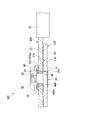
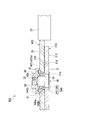
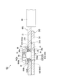
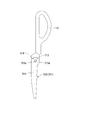
- FIG. 2 is a cross-sectional view taken along line II-II in FIG. It is a top view of the 1st blade body of the scissors which concern on 1st Embodiment. It is a top view of the 2nd blade body of the scissors which concern on 1st Embodiment. It is a top view of the support shaft of the scissors which concern on 1st Embodiment. It is explanatory drawing which shows the modification of an urging member, Comprising: It is sectional drawing in the part corresponded to the II-II line
- FIG. 11 is an explanatory view showing a modification of the urging member, and is a cross-sectional view of a portion corresponding to the line XII-XII in FIG. 10. It is explanatory drawing of the scissors which concern on 6th Embodiment of this invention, Comprising: It is sectional drawing in the part corresponded to the XII-XII line
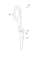
- FIG. 1 is a plan view of scissors according to the first embodiment.
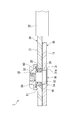
- 2 is a cross-sectional view taken along line II-II in FIG.
- the scissors 1 is a so-called western bowl.
- the scissors 1 are a first blade body 10 that holds the support shaft 30, and a second blade that is provided so as to overlap the first blade body 10 and that is rotatably supported by the support shaft 30 via a slide bearing 40. And a body 20.
- the first blade body 10 and the second blade body 20 are curved so as to gradually approach each other from the support shaft 30 toward the tip.
- the second blade body 20 side when viewed from the first blade body 10 is referred to as the upper side, and the opposite side is the lower side. The side.
- FIG. 3 is a plan view of the first blade body of the scissors according to the first embodiment.
- the first blade body 10 includes a first base 11 formed of a metal plate having a thickness in the axial direction, and a first grip portion 12 attached to a base end portion of the first base 11. It is equipped with.
- a blade line is formed on the first base 11.
- the upper surface of the first base 11 is formed in a planar shape.
- a support shaft insertion hole 13 through which the support shaft 30 (see FIG. 2) is inserted is formed in the first base 11.
- the support shaft insertion hole 13 is formed in a circular shape in cross section and penetrates the first base 11 with a constant inner diameter in the axial direction.
- the first grip portion 12 is provided on the proximal end side of the first blade body 10.
- the first grip portion 12 is formed in an annular shape, for example, from a resin material or the like.
- FIG. 4 is a plan view of the second blade body of the scissors according to the first embodiment.
- the second blade body 20 includes a second base 21 formed of a metal plate having a thickness in the axial direction, and a second gripping portion 22 attached to the base end portion of the second base 21. It is equipped with.
- a blade line is formed on the second base 21.
- the lower surface of the second base 21 is formed in a planar shape.
- the second base 21 is formed with a bearing holding hole 23 into which a slide bearing 40 (see FIG. 2) is press-fitted or inserted.
- the bearing holding hole 23 is formed in a circular shape in cross section, and penetrates the second base 21 with a constant inner diameter in the axial direction.
- the inner diameter of the bearing holding hole 23 is set larger than the inner diameter of the support shaft insertion hole 13 (see FIG. 2).
- An inner flange portion 24 (regulating portion) is provided at the lower end portion of the bearing holding hole 23.
- the inner flange portion 24 restricts the movement of the sliding bearing 40 toward the first blade body 10 with respect to the second blade body 20 (see FIG. 2).
- the second grip portion 22 is provided on the proximal end side of the second blade body 20.
- the second grip portion 22 is formed in an annular shape from, for example, a resin material.
- a support shaft 30 is press-fitted into the support shaft insertion hole 13 of the first blade body 10.
- the support shaft 30 has a large-diameter portion 31 formed at the lower end, a small-diameter portion 32 that is continuous with the upper end of the large-diameter portion 31, and a male screw portion 33 that is smaller in diameter than the small-diameter portion 32 and is continuous with the upper end of the small-diameter portion 32.
- the large diameter part 31, the small diameter part 32, and the male screw part 33 are arranged coaxially.
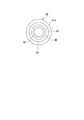
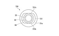
- FIG. 5 is a plan view of the support shaft of the scissors according to the first embodiment.
- the large-diameter portion 31 is formed in a circular shape in cross section and is press-fitted into the support shaft insertion hole 13.
- An outer flange portion 31 a is formed at the lower end portion of the large diameter portion 31.
- the upper surface of the outer flange portion 31 a is in contact with the lower surface of the first base 11.
- a step surface 34 between the large diameter portion 31 and the small diameter portion 32 is flush with the upper surface of the first base 11.
- the small-diameter portion 32 is formed in a circular shape when viewed in cross section.
- the upper end portion of the small diameter portion 32 is located above the upper surface of the second base 21.
- an annular slide bearing 40 is slidably inserted in the small diameter portion 32.
- the slide bearing 40 is made of a resin material having good sliding properties such as polyacetal, polyamide, polytetrafluoroethylene, polyphenylene sulfide, polyethylene, elastomer, polyolefin, thermosetting resin, so-called super engineering plastics, and the like.
- a resin material having good sliding properties such as polyacetal, polyamide, polytetrafluoroethylene, polyphenylene sulfide, polyethylene, elastomer, polyolefin, thermosetting resin, so-called super engineering plastics, and the like.
- an oil-impregnated bearing for example, an oil-impregnated bearing, a slide bearing formed of ceramic or the like, or a slide bearing coated with a hard film such as diamond-like carbon on the surface may be used. Is possible.
- the slide bearing 40 is uniformly formed along the axial direction. The upper end surface of the slide bearing 40 is flush with
- a fixing member 50 is mounted on the side opposite to the first blade body 10 (ie, above the sliding bearing 40) across the sliding bearing 40 of the support shaft 30.
- the fixing member 50 is a nut member having a circular shape in a plan view and screwed to the male screw portion 33 of the support shaft 30.
- the fixing member 50 is formed with an annular surrounding wall 51 extending downward from the outer peripheral edge thereof. The lower end edge of the surrounding wall 51 is slightly separated from the upper surface of the second base 21.
- the surrounding wall 51 surrounds the upper end portion of the slide bearing 40 from the outside in the radial direction.
- a biasing member 60 is disposed between the sliding bearing 40 and the fixed member 50.
- the biasing member 60 is a disc spring.
- the inner peripheral edge of the urging member 60 is slidably in contact with the upper end surface of the slide bearing 40 from above.
- the outer peripheral edge of the urging member 60 is in contact with the lower surface of the fixing member 50 from below. Accordingly, the sliding bearing 40 is urged toward the first blade body 10 by the urging member 60 with respect to the fixed member 50.
- the 2nd blade 20 since the 2nd blade 20 is rotatably supported by the support shaft 30 via the slide bearing 40, the movement of the 1st blade 10 and the 2nd blade 20 is carried out. Can be made smooth. Moreover, at least one of the second blade body 20 and the slide bearing 40 (second blade body 20 in the present embodiment) moves the slide bearing 40 toward the first blade body 10 with respect to the second blade body 20. An inner flange portion 24 for restricting the above is provided. For this reason, the sliding bearing 40 is biased toward the first blade body 10 by the biasing member 60 so that the biasing force of the biasing member 60 acting on the sliding bearing 40 is applied to the second blade body 20. Thus, the second blade body 20 can be pressed toward the first blade body 10. Thereby, the 1st blade body 10 and the 2nd blade body 20 are always press-contacted, and cutting performance can be maintained. Therefore, scissors 1 that can maintain excellent cutting performance can be provided.
- the fixing member 50 covers the upper end portion of the sliding bearing 40 with the bottom surface and the surrounding wall 51, dust or the like enters the sliding portion between the sliding bearing 40 and the support shaft 30 to cause sliding friction. The increase can be suppressed. Therefore, the first blade body 10 and the second blade body 20 can be moved smoothly.
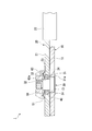
- FIG. 6 is an explanatory view showing a modification of the urging member, and is a cross-sectional view taken along the line II-II in FIG.
- the urging member 60 may have a seating surface 60a on the sliding bearing 40 side. According to this configuration, since the urging member 60 can be brought into contact with the slide bearing 40 on the surface, an increase in sliding friction of the slide bearing 40 can be suppressed. For this reason, the movement of the 1st blade 10 and the 2nd blade 20 can be made smooth.
- FIG. 7 is an explanatory view of the scissors according to the second embodiment, and is a cross-sectional view taken along a line II-II in FIG.
- the bearing holding hole 23 of the second blade body 20 includes an inner flange portion 24.
- the second embodiment shown in FIG. 7 differs from the first embodiment in that the bearing holding hole 123 of the second blade body 120 penetrates with a constant inner diameter in the axial direction.
- the plain bearing 40 is formed uniformly along the axial direction.
- the slide bearing 140 is different from the first embodiment in that it includes an outer flange 141 (regulating portion).
- symbol is attached
- the plain bearing 140 includes an outer flange 141 that projects outward in the radial direction.
- the outer flange 141 is formed on the outer peripheral edge of the slide bearing 140 on the side opposite to the first blade body 10 (that is, the upper side).
- the lower surface of the outer flange 141 is in contact with the upper surface of the second base 121 of the second blade body 120.
- the outer flange 141 regulates the movement of the slide bearing 140 toward the first blade body 10 with respect to the second blade body 120.
- the second blade body 120 is similar to the conventional scissors. Moreover, it can be manufactured at low cost.
- FIG. 8 is an explanatory view of the scissors according to the third embodiment, and is a cross-sectional view taken along the line II-II in FIG.
- the slide bearing 40 and the biasing member 60 are in contact with each other.
- the third embodiment shown in FIG. 8 differs from the first embodiment in that, for example, an annular spacer 61 is interposed between the slide bearing 40 and the biasing member 60. Yes.
- the spacer 61 is interposed between the sliding bearing 40 and the biasing member 60, it is possible to prevent the sliding bearing 40 and the biasing member 60 from being in direct sliding contact. it can. For this reason, the increase in the sliding friction of the sliding bearing 40 can be suppressed, and the movement of the first blade body 10 and the second blade body 20 can be made smooth. Therefore, the scissors 201 that can maintain excellent cutting performance can be provided.
- FIG. 9 is an explanatory view showing a modification of the urging member, and is a cross-sectional view taken along a line II-II in FIG.
- the plain bearing 40 is urged toward the first blade body 10 by an annular urging member 160 formed of an elastic material such as rubber, silicon rubber, or urethane. May be.
- FIG. 10 is a plan view of the scissors in the closed state according to the fourth embodiment.
- FIG. 11 is a plan view of the scissors in the open state according to the fourth embodiment.
- 12 is a cross-sectional view taken along line XII-XII in FIG.
- the first blade body 10 and the second blade body 20 are directly overlapped.
- the fourth embodiment shown in FIGS. 10 to 12 the first embodiment is that a sliding member 370 is provided between the first blade body 310 and the second blade body 20. Is different.
- the scissors 301 are provided with a sliding member 370.
- the sliding member 370 is provided at a position closer to the base end side than the support shaft 30 of the first blade body 310 and the second blade body 20, and the first blade body 310 and the second blade body 20 are always opposed to each other. ing.
- the sliding member 370 is formed so as to extend along the circumferential direction centering on the support shaft 30 when viewed from the axial direction.
- the sliding member 370 is disposed in a receiving groove 314 formed on the upper surface of the first base 311 of the first blade body 310.
- the housing groove 314 is formed corresponding to the shape of the sliding member 370.
- the upper surface of the sliding member 370 is in contact with the lower surface of the second base 21 of the second blade body 20.
- the sliding member 370 biases the first blade body 310 and the second blade body 20 in a direction away from each other.
- the sliding member 370 is provided at a position where the first blade body 310 and the second blade body 20 always face each other, the first blade body 310, the second blade body 20, and the like.
- the sliding resistance can be reduced. Therefore, the movement of the first blade body 310 and the second blade body 20 can be made smooth.
- the sliding member 370 is provided on the proximal end side with respect to the support shaft 30 of the first blade body 310 and the second blade body 20, and in a direction in which the first blade body 310 and the second blade body 20 are separated from each other. Since the biasing is performed, the distal end sides of the first blade body 310 and the second blade body 20 can be brought close to each other with the support shaft 30 as a fulcrum. Thereby, the blade line
- FIG. 13 is an explanatory diagram of scissors according to the fifth embodiment, and is a cross-sectional view of a portion corresponding to the line XII-XII in FIG.
- the slide bearing 40 is formed uniformly along the axial direction.
- the outer peripheral surface 440a (regulating portion) of the slide bearing 440 is gradually reduced in diameter from the fixed member 50 side toward the first blade body 310 side. This is different from the fourth embodiment.
- the bearing holding hole 23 of the 2nd blade body 20 has penetrated with the fixed internal diameter in the axial direction.
- the inner peripheral surface 423a (regulator) of the bearing holding hole 423 of the second blade 420 is gradually increased from the fixing member 50 side toward the first blade 310 side. This is different from the fourth embodiment in that the diameter is reduced.
- the outer peripheral surface 440 a of the slide bearing 440 is an inclined surface that gradually decreases in diameter from the fixing member 50 side toward the first blade body 310 side.
- the inner peripheral surface 423a of the bearing holding hole 423 is an inclined surface that gradually decreases in diameter from the fixed member 50 side toward the first blade body 310 side so as to correspond to the outer peripheral surface 440a of the slide bearing 440.
- the outer peripheral surface 440 a of the slide bearing 440 and the inner peripheral surface 423 a of the bearing holding hole 423 restrict the movement of the slide bearing 440 toward the first blade body 310 with respect to the second blade body 420.
- a part of the urging force to the first blade body 310 side that acts on the slide bearing 440 by the urging member 60 is used for the outer peripheral surface 440 a of the slide bearing 440 and the bearing holding hole 423.
- the sliding bearing 440 can be directed outward in the radial direction. For this reason, it is possible to suppress the occurrence of a radial gap between the outer peripheral surface 440a of the slide bearing 440 and the inner peripheral surface 423a of the bearing holding hole 423.
- the scissors 401 capable of maintaining excellent cutting performance can be provided.
- FIG. 14 is an explanatory view showing a modification of the urging member, and is a cross-sectional view of a portion corresponding to the line XII-XII in FIG.
- an annular attachment formed of an elastic material such as rubber, silicon rubber, or urethane is used.
- a biasing member 160 can be used.
- FIG. 15 is an explanatory view of the scissors according to the sixth embodiment, and is a cross-sectional view taken along the line XII-XII in FIG.
- the plain bearing 440 is configured as one member.
- the sliding bearing 540 is different from the fifth embodiment in that it includes a first bearing 542 and a second bearing 543.
- the sliding bearing 540 includes a first bearing 542 that contacts the second blade body 420, and a second bearing 543 that is disposed between the first bearing 542 and the support shaft 30. Yes.
- the support shaft 30 is slidably inserted into the second bearing 543.
- the second bearing 543 is formed in an annular shape from, for example, a resin material or a metal material.
- the outer peripheral surface 543a of the second bearing 543 is an inclined surface that gradually decreases in diameter from the fixing member 50 side toward the first blade body 310 side.
- the second bearing 543 is biased toward the first blade body 310 by the biasing member 60.
- the first bearing 542 is formed in an annular shape from a resin material, for example.
- the inner peripheral surface 542a of the first bearing 542 is an inclined surface that gradually decreases in diameter from the fixing member 50 side toward the first blade body 310 side.
- the inner peripheral surface 542a of the first bearing 542 is formed to correspond to the outer peripheral surface 543a of the second bearing 543.
- the outer peripheral surface 542b of the first bearing 542 is an inclined surface that gradually decreases in diameter from the fixed member 50 side toward the first blade body 310 side.
- the outer peripheral surface 542b of the first bearing 542 is formed to correspond to the inner peripheral surface 423a of the bearing holding hole 423.
- the slide bearing 540 includes the first bearing 542 that contacts the second blade body 420, and the second bearing 543 that is disposed between the first bearing 542 and the support shaft 30. Therefore, when the second blade body 420 rotates with respect to the support shaft 30, even when the second bearing 543 is difficult to rotate with respect to the support shaft 30 due to the biasing by the biasing member 60.
- the first bearing 542 can be rotated with respect to the second bearing 543. Thereby, the movement of the 1st blade 310 and the 2nd blade 420 can be made smooth.
- FIG. 16 is an explanatory view of the scissors according to the seventh embodiment, and is a cross-sectional view taken along the line XII-XII in FIG.
- the second bearing 543 is configured as one member.
- the second bearing 643 is different from the sixth embodiment in that it includes an outer member 644 and an inner member 645.
- the plain bearing 640 includes a first bearing 542 and a second bearing 643.
- the second bearing 643 includes an annular outer member 644 that contacts the inner peripheral surface 542 a of the first bearing 542, and an annular inner member 645 disposed between the outer member 644 and the support shaft 30. ing.
- the support shaft 30 is slidably inserted into the inner member 645.
- the inner member 645 is made of, for example, a resin material.
- the outer peripheral surface 645a of the inner member 645 is an inclined surface that gradually decreases in diameter from the fixed member 50 side toward the first blade body 310 side.
- the inner member 645 is biased toward the first blade body 310 by the biasing member 60.
- the outer member 644 is formed of a material different from that of the first bearing 542 and the inner member 645, such as a metal material.
- the inner peripheral surface 644a of the outer member 644 is an inclined surface that gradually decreases in diameter from the fixing member 50 side toward the first blade body 310 side.
- the inner peripheral surface 644 a of the outer member 644 is formed to correspond to the outer peripheral surface 645 a of the inner member 645.
- the outer peripheral surface 644b of the outer member 644 is an inclined surface that gradually decreases in diameter from the fixing member 50 side toward the first blade body 310 side.
- the outer peripheral surface 644 b of the outer member 644 is formed to correspond to the inner peripheral surface 542 a of the first bearing 542.
- the second bearing 643 is disposed between the annular outer member 644 that contacts the inner peripheral surface 542a of the first bearing 542, the outer member 644, and the support shaft 30.
- the inner member 645 of the second bearing 643 is supported by the biasing force of the biasing member 60 when the second blade body 420 rotates with respect to the support shaft 30. Even when it becomes difficult to rotate with respect to the shaft 30, the outer member 644 and the first bearing 542 of the second bearing 643 can be rotated with respect to the inner member 645 of the second bearing 643. Thereby, the movement of the 1st blade 310 and the 2nd blade 420 can be made smooth.
- the outer member 644 of the second bearing 643 is formed of a material different from that of the first bearing 542 and the inner member 645 of the second bearing 643, the contact point between the outer member 644 and the first bearing 542, and The sliding resistance at the contact point between the outer member 644 and the inner member 645 can be reduced. Therefore, the movement of the first blade body 310 and the second blade body 420 can be made smoother.
- FIG. 17 is a plan view of the first blade body of the scissors according to the eighth embodiment.
- FIG. 18 is a plan view of the support shaft of the scissors according to the eighth embodiment.
- FIG. 19 is a side view of the support shaft of the scissors according to the eighth embodiment.
- the support shaft insertion hole 13 is formed in a circular shape in a cross-sectional view.
- the eighth embodiment shown in FIG. 17 is different from the first embodiment in that the support shaft insertion hole 713 is formed in a non-circular shape (an irregular shape) in a cross-sectional view.
- the large diameter part 31 of the support shaft 30 is formed in circular shape by the cross sectional view.
- the large-diameter portion 731 of the support shaft 730 is different from the first embodiment in that it is formed in a non-circular shape (an irregular shape) in a cross-sectional view. Yes.
- the support shaft 730 includes a large-diameter portion 731 that is fitted into the support shaft insertion hole 713 (see FIG. 17).
- the large-diameter portion 731 is formed in a columnar shape, and two-sided portions 731b (anti-rotation portions) are formed on both sides in a predetermined radial direction orthogonal to the axial direction. As shown in FIGS.
- the two-side chamfered portion 731 b is formed in a shape corresponding to the two-side chamfered surface 713 a of the support shaft insertion hole 713. Accordingly, the two-side chamfered surface 713a and the two-side chamfered portion 731b prevent the first blade body 710 and the support shaft 730 from rotating relative to each other.
- the support shaft 730 is press-fitted in a state where it can be attached to and detached from the first blade body 710 and is not relatively rotatable.
- the fixing member 50 when the fixing member 50 (see FIG. 2) is attached to the support shaft 730 in a state where the first blade body 710 is supported, the first blade body 710 and the support shaft 730 cannot be rotated relative to each other.
- the two-side chamfered surface 713a and the two-side chamfered portion 731b can prevent the support shaft 730 from rotating with respect to the first blade body 710. Accordingly, the fixing member 50 can be easily attached to and detached from the support shaft 730, and the first blade body 710 and the second blade body 20 (see FIG. 2) can be easily disassembled and assembled.
- the first blade body 710 and the support shaft 730 can be disassembled and cannot be rotated relative to each other by removing the support shaft insertion hole 713 and the support shaft 730 in two directions (two chamfering).
- the first blade body and the support shaft need only be disassembled from each other and cannot rotate relative to each other, and these connecting portions may be formed in a noncircular shape such as a polygonal shape when viewed from the axial direction.
- the first blade body and the support shaft may be prevented from rotating relative to each other by a detent portion such as a pin.
- FIG. 20 is an explanatory view of the scissors according to the ninth embodiment, and is a cross-sectional view taken along the line II-II in FIG.
- the lower end surface of the support shaft 30 is formed in a flat shape.
- the lower end surface of the support shaft 830 (the end surface on the first blade body 10 side in the axial direction) has a groove portion 834 extending along the direction orthogonal to the axial direction. It is different from the first embodiment in that it is formed.
- the support shaft 830 can be fixed by inserting a driver or the like into the groove portion 834. Accordingly, the fixing member 50 can be easily attached to and detached from the support shaft 830, and the first blade body 10 and the second blade body 20 can be easily disassembled and assembled.
- the fixing member is a nut member that is screwed to the upper end portion (male screw portion) of the support shaft, but is not limited thereto.
- the fixing member 950 may be a caulking portion obtained by buckling and deforming the upper end portion of the support shaft 930.
- a 2nd blade body is rotatably supported by a support shaft via a slide bearing, it makes the movement of a 1st blade body and a 2nd blade body smooth. Can do.
- at least one of the second blade body and the sliding bearing is provided with a restricting portion that restricts the movement of the sliding bearing toward the first blade body with respect to the second blade body. For this reason, when the sliding bearing is biased toward the first blade body by the biasing member, the biasing force of the biasing member acting on the sliding bearing is applied to the second blade body, and the second blade body is moved. It can press toward a 1st blade.
Landscapes
- Life Sciences & Earth Sciences (AREA)
- Forests & Forestry (AREA)
- Engineering & Computer Science (AREA)
- Mechanical Engineering (AREA)
- Scissors And Nippers (AREA)
- Lubricants (AREA)
- Sliding-Contact Bearings (AREA)
Abstract
この切断機は、支持軸と、前記支持軸を保持する第1刃体と、前記支持軸に装着されたすべり軸受と、前記第1刃体に重ね合わさるように設けられ、かつ前記支持軸に前記すべり軸受を介して回転自在に支持された第2刃体と、前記支持軸の前記すべり軸受を挟んで前記第1刃体とは反対側に配置された固定部材と、前記すべり軸受と前記固定部材との間に配置された付勢部材と、を備える。前記第2刃体および前記すべり軸受のうち少なくともいずれか一方には、前記すべり軸受の前記第2刃体に対する前記第1刃体側への移動を規制する規制部が設けられ、前記すべり軸受は、前記付勢部材により前記第1刃体側に向かって付勢されている。
Description
本発明は、切断機およびはさみに関するものである。
本願は、2015年7月6日に、日本に出願された特願2015-135496号に基づき優先権を主張し、その内容をここに援用する。
本願は、2015年7月6日に、日本に出願された特願2015-135496号に基づき優先権を主張し、その内容をここに援用する。
切断機を具備した工具として、例えばはさみが挙げられる。はさみは、一対の刃体と、一対の刃体を支持する支持軸と、を備えている(例えば、特許文献1参照)。このはさみでは、一方の刃体が、支持軸に摺動自在に支持されている。
しかしながら、上記従来の切断機を具備するはさみでは、支持軸と支持軸に支持された刃体との摺動により支持軸が摩耗して、刃体にがたつきが生じる場合がある。この場合には、一対の刃体同士の間に隙間が形成されて噛み合わせが悪化し、切断性能が低下する可能性がある。
本発明は、優れた切断性能を維持できる切断機およびはさみを提供するものである。
本発明の第1の態様による切断機は、支持軸と、前記支持軸を保持する第1刃体と、前記支持軸に装着されたすべり軸受と、前記第1刃体に重ね合わさるように設けられ、かつ前記支持軸にすべり軸受を介して回転自在に支持された第2刃体と、前記支持軸の前記すべり軸受を挟んで前記第1刃体とは反対側に配置された固定部材と、前記すべり軸受と前記固定部材との間に配置された付勢部材と、を備え、前記第2刃体および前記すべり軸受のうち少なくともいずれか一方に、前記すべり軸受の前記第2刃体に対する前記第1刃体側への移動を規制する規制部が設けられ、前記すべり軸受が、前記付勢部材により前記第1刃体側に向かって付勢されている。
上記のように構成することで、第2刃体は、支持軸にすべり軸受を介して回転自在に支持されるため、第1刃体と第2刃体との動きを円滑にすることができる。しかも、第2刃体およびすべり軸受のうち少なくともいずれか一方には、すべり軸受の第2刃体に対する第1刃体側への移動を規制する規制部が設けられている。このため、すべり軸受が付勢部材により第1刃体側に向かって付勢されることで、すべり軸受に作用する付勢部材の付勢力を第2刃体に作用させて、第2刃体を第1刃体に向かって押圧することができる。これにより、第1刃体と第2刃体とが常時圧接され、切断性能を維持することができる。したがって、優れた切断性能を維持できる切断機を提供できる。
上記のように構成することで、第2刃体は、支持軸にすべり軸受を介して回転自在に支持されるため、第1刃体と第2刃体との動きを円滑にすることができる。しかも、第2刃体およびすべり軸受のうち少なくともいずれか一方には、すべり軸受の第2刃体に対する第1刃体側への移動を規制する規制部が設けられている。このため、すべり軸受が付勢部材により第1刃体側に向かって付勢されることで、すべり軸受に作用する付勢部材の付勢力を第2刃体に作用させて、第2刃体を第1刃体に向かって押圧することができる。これにより、第1刃体と第2刃体とが常時圧接され、切断性能を維持することができる。したがって、優れた切断性能を維持できる切断機を提供できる。
本発明の第2の態様によれば、本発明の第1の態様に係る切断機において、前記すべり軸受と前記付勢部材との間に、スペーサが介在していてもよい。
上記のように構成した場合、すべり軸受と付勢部材とが直接摺接することを抑制できるため、すべり軸受の摺動摩擦の増加を抑制できる。このため、第1刃体と第2刃体との動きを円滑にすることができる。
上記のように構成した場合、すべり軸受と付勢部材とが直接摺接することを抑制できるため、すべり軸受の摺動摩擦の増加を抑制できる。このため、第1刃体と第2刃体との動きを円滑にすることができる。
本発明の第3の態様によれば、本発明の第1の態様または第2の態様に係る切断機において、前記付勢部材が、前記すべり軸受側に座面を有してもよい。
上記のように構成した場合、付勢部材をすべり軸受側の部材に対して面で接触させることができるため、すべり軸受の摺動摩擦の増加を抑制できる。このため、第1刃体と第2刃体との動きを円滑にすることができる。
上記のように構成した場合、付勢部材をすべり軸受側の部材に対して面で接触させることができるため、すべり軸受の摺動摩擦の増加を抑制できる。このため、第1刃体と第2刃体との動きを円滑にすることができる。
本発明の第4の態様によれば、本発明の第1の態様から第3の態様のいずれか一の態様に係る切断機において、前記すべり軸受の外周面が、前記固定部材側から前記第1刃体側に向かうに従い漸次縮径し、前記第2刃体が、前記すべり軸受を保持する軸受保持孔を備え、前記軸受保持孔が、前記すべり軸受の前記外周面に対応するように、前記固定部材側から前記第1刃体側に向かうに従い漸次縮径する内周面を備えてもよい。
上記のように構成した場合、すべり軸受に作用する付勢部材の第1刃体側への付勢力の一部を、すべり軸受の外周面と軸受保持孔の内周面との接触箇所において、すべり軸受の径方向の外側へ向けることができる。このため、すべり軸受の外周面と軸受保持孔の内周面との間に、すべり軸受の径方向の隙間が生じることを抑制できる。これにより、第2刃体にがたつきが生じることが抑制されるので、第1刃体と第2刃体とを安定して圧接させることが可能となる。したがって、優れた切断性能を維持できる切断機を提供できる。
上記のように構成した場合、すべり軸受に作用する付勢部材の第1刃体側への付勢力の一部を、すべり軸受の外周面と軸受保持孔の内周面との接触箇所において、すべり軸受の径方向の外側へ向けることができる。このため、すべり軸受の外周面と軸受保持孔の内周面との間に、すべり軸受の径方向の隙間が生じることを抑制できる。これにより、第2刃体にがたつきが生じることが抑制されるので、第1刃体と第2刃体とを安定して圧接させることが可能となる。したがって、優れた切断性能を維持できる切断機を提供できる。
本発明の第5の態様によれば、本発明の第1の態様から第4の態様のいずれか一の態様に係る切断機において、前記すべり軸受が、前記第2刃体に接触する第1軸受と、前記第1軸受と前記支持軸との間に配置され、前記支持軸が摺動自在に挿通されるとともに、前記付勢部材により前記第1刃体側に向かって付勢される第2軸受と、を備え、前記第2軸受の外周面が、前記固定部材側から前記第1刃体側に向かうに従い漸次縮径し、前記第1軸受の内周面が、前記第2軸受の前記外周面に対応するように、前記固定部材側から前記第1刃体側に向かうに従い漸次縮径している構成を採用してもよい。
上記のように構成した場合、すべり軸受は、第2刃体に接触する第1軸受と、第1軸受と支持軸との間に配置される第2軸受と、を備えているため、支持軸に対して第2刃体が回転する際に、付勢部材による付勢により第2軸受が支持軸に対して回転し難くなった場合でも、第1軸受を第2軸受に対して回転させることができる。これにより、第1刃体と第2刃体との動きを円滑にすることができる。
この際、第2軸受の外周面は、固定部材側から第1刃体側に向かうに従い漸次縮径しているため、第2軸受の外周面と第1軸受の内周面との接触箇所において、第2軸受に作用する付勢部材の第1刃体側への付勢力の一部を第2軸受の径方向の外側へ向けることができる。このため、第1軸受と第2軸受との間に、第2軸受の径方向の隙間が生じることを抑制できる。したがって、第1軸受および第2軸受ががたつくことを抑制でき、第2刃体にがたつきが生じることを抑制できる。
上記のように構成した場合、すべり軸受は、第2刃体に接触する第1軸受と、第1軸受と支持軸との間に配置される第2軸受と、を備えているため、支持軸に対して第2刃体が回転する際に、付勢部材による付勢により第2軸受が支持軸に対して回転し難くなった場合でも、第1軸受を第2軸受に対して回転させることができる。これにより、第1刃体と第2刃体との動きを円滑にすることができる。
この際、第2軸受の外周面は、固定部材側から第1刃体側に向かうに従い漸次縮径しているため、第2軸受の外周面と第1軸受の内周面との接触箇所において、第2軸受に作用する付勢部材の第1刃体側への付勢力の一部を第2軸受の径方向の外側へ向けることができる。このため、第1軸受と第2軸受との間に、第2軸受の径方向の隙間が生じることを抑制できる。したがって、第1軸受および第2軸受ががたつくことを抑制でき、第2刃体にがたつきが生じることを抑制できる。
本発明の第6の態様によれば、本発明の第5の態様に係る切断機において、前記第2軸受が、前記第1軸受の前記内周面に接触する円環状の外側部材と、前記外側部材と前記支持軸との間に配置されるとともに、前記付勢部材により前記第1刃体側に向かって付勢される円環状の内側部材と、を備え、前記内側部材の外周面が、前記固定部材側から前記第1刃体側に向かうに従い漸次縮径し、前記外側部材の内周面が、前記内側部材の前記外周面に対応するように、前記固定部材側から前記第1刃体側に向かうに従い漸次縮径している構成を採用してもよい。
上記のように構成した場合、第2軸受が、第1軸受の内周面に接触する円環状の外側部材と、外側部材と支持軸との間に配置される円環状の内側部材と、を備えているため、支持軸に対して第2刃体が回転する際に、付勢部材による付勢により第2軸受の内側部材が支持軸に対して回転し難くなった場合でも、第2軸受の外側部材および第1軸受を第2軸受の内側部材に対して回転させることができる。これにより、第1刃体と第2刃体との動きを円滑にすることができる。
この際、第2軸受の内側部材の外周面は、固定部材側から第1刃体側に向かうに従い漸次縮径しているため、内側部材の外周面と第2軸受の外側部材の内周面との接触箇所において、内側部材に作用する付勢部材の第1刃体側への付勢力の一部を内側部材の径方向の外側へ向けることができる。このため、外側部材と内側部材との間に、内側部材の径方向の隙間が生じることを抑制できる。したがって、外側部材および内側部材ががたつくことを抑制でき、第2刃体にがたつきが生じることを抑制できる。
上記のように構成した場合、第2軸受が、第1軸受の内周面に接触する円環状の外側部材と、外側部材と支持軸との間に配置される円環状の内側部材と、を備えているため、支持軸に対して第2刃体が回転する際に、付勢部材による付勢により第2軸受の内側部材が支持軸に対して回転し難くなった場合でも、第2軸受の外側部材および第1軸受を第2軸受の内側部材に対して回転させることができる。これにより、第1刃体と第2刃体との動きを円滑にすることができる。
この際、第2軸受の内側部材の外周面は、固定部材側から第1刃体側に向かうに従い漸次縮径しているため、内側部材の外周面と第2軸受の外側部材の内周面との接触箇所において、内側部材に作用する付勢部材の第1刃体側への付勢力の一部を内側部材の径方向の外側へ向けることができる。このため、外側部材と内側部材との間に、内側部材の径方向の隙間が生じることを抑制できる。したがって、外側部材および内側部材ががたつくことを抑制でき、第2刃体にがたつきが生じることを抑制できる。
本発明の第7の態様によれば、本発明の第1の態様から第6の態様のいずれか一の態様に係る切断機において、前記第1刃体と前記第2刃体とが常時対向する箇所には、摺動部材が設けられていてもよい。
上記のように構成した場合、摺動部材によって、第1刃体と第2刃体との摺動抵抗を低減することができる。したがって、第1刃体と第2刃体との動きを円滑にすることができる。
上記のように構成した場合、摺動部材によって、第1刃体と第2刃体との摺動抵抗を低減することができる。したがって、第1刃体と第2刃体との動きを円滑にすることができる。
本発明の第8の態様によれば、本発明の第7の態様に係る切断機において、前記摺動部材が、前記第1刃体および前記第2刃体の前記支持軸よりも基端側に設けられ、前記第1刃体と前記第2刃体とを互いに離間する方向に付勢する構成を採用してもよい。
上記のように構成した場合、摺動部材は、第1刃体および第2刃体の支持軸よりも基端側に設けられ、第1刃体と第2刃体とを互いに離間する方向に付勢することにより、支持軸を支点にして第1刃体および第2刃体の先端側同士を互いに接近させることができる。これにより、第1刃体および第2刃体の先端側に設けられる刃線同士を常時圧接させることができ、切断性能を向上させることができる。
上記のように構成した場合、摺動部材は、第1刃体および第2刃体の支持軸よりも基端側に設けられ、第1刃体と第2刃体とを互いに離間する方向に付勢することにより、支持軸を支点にして第1刃体および第2刃体の先端側同士を互いに接近させることができる。これにより、第1刃体および第2刃体の先端側に設けられる刃線同士を常時圧接させることができ、切断性能を向上させることができる。
本発明の第9の態様によれば、本発明の第1の態様から第8の態様のいずれか一の態様に係る切断機において、前記第1刃体および前記支持軸少なくとも一方に、前記第1刃体および前記支持軸が相対回転できないようにする回り止め部が設けられていてもよい。
上記のように構成した場合、第1刃体を支えた状態で支持軸に固定部材を装着する際に、回り止め部によって支持軸が第1刃体に対して回転することを防止できる。したがって、固定部材の支持軸への着脱を容易に行うことが可能となり、第1刃体および第2刃体の分解や組み立てを容易に行うことができる。
上記のように構成した場合、第1刃体を支えた状態で支持軸に固定部材を装着する際に、回り止め部によって支持軸が第1刃体に対して回転することを防止できる。したがって、固定部材の支持軸への着脱を容易に行うことが可能となり、第1刃体および第2刃体の分解や組み立てを容易に行うことができる。
本発明の第10の態様によれば、本発明の第1の態様から第9の態様のいずれか一の態様に係る切断機において、前記支持軸の軸方向における前記第1刃体側の端面に、溝部が形成されていてもよい。
上記のように構成した場合、溝部にドライバ等を差し込んで支持軸を固定することができる。これにより、固定部材の支持軸への着脱を容易に行うことが可能となり、第1刃体および第2刃体の分解や組み立てを容易に行うことができる。
上記のように構成した場合、溝部にドライバ等を差し込んで支持軸を固定することができる。これにより、固定部材の支持軸への着脱を容易に行うことが可能となり、第1刃体および第2刃体の分解や組み立てを容易に行うことができる。
本発明の第11の態様によるはさみは、本発明の第1の態様から第10の態様のいずれか一の態様に係る切断機と、前記第1刃体の基端側に設けられた第1把持部と、前記第2刃体の基端側に設けられた第2把持部と、を備える。
上記構成によれば、はさみは、上述した切断機を備えるため、優れた切断性能を維持できる。
上記構成によれば、はさみは、上述した切断機を備えるため、優れた切断性能を維持できる。
上記各態様の切断機によれば、第2刃体は、支持軸にすべり軸受を介して回転自在に支持されるため、第1刃体と第2刃体との動きを円滑にすることができる。しかも、第2刃体およびすべり軸受のうち少なくともいずれか一方には、すべり軸受の第2刃体に対する第1刃体側への移動を規制する規制部が設けられている。このため、すべり軸受が付勢部材により第1刃体側に向かって付勢されることで、すべり軸受に作用する付勢部材の付勢力を第2刃体に作用させて、第2刃体を第1刃体に向かって押圧することができる。これにより、第1刃体と第2刃体とが常時圧接され、切断性能を維持することができる。また、この切断機を具備するはさみにおいても、同様の作用効果を得ることができる。
したがって、本発明の上記各態様によれば、優れた切断性能を維持できる切断機およびはさみを提供できる。
したがって、本発明の上記各態様によれば、優れた切断性能を維持できる切断機およびはさみを提供できる。
以下、本発明の各実施形態を図面に基づいて説明する。
[第1実施形態]
最初に、第1実施形態のはさみ1(切断機)について説明する。
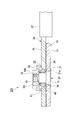
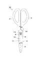
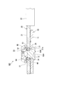
図1は、第1実施形態に係るはさみの平面図である。図2は、図1のII-II線における断面図である。
図1および図2に示すように、はさみ1は、いわゆる洋鋏である。はさみ1は、支持軸30を保持する第1刃体10と、第1刃体10に重ね合わさるように設けられ、かつ支持軸30にすべり軸受40を介して回転自在に支持された第2刃体20と、を備えている。第1刃体10および第2刃体20は、支持軸30から先端に向かうに従って、漸次互いに接近するように湾曲している。なお、以下の説明では、支持軸30の軸方向(以下、単に「軸方向」という。)において、第1刃体10から見て第2刃体20側を上側といい、その反対側を下側という。
[第1実施形態]
最初に、第1実施形態のはさみ1(切断機)について説明する。
図1は、第1実施形態に係るはさみの平面図である。図2は、図1のII-II線における断面図である。
図1および図2に示すように、はさみ1は、いわゆる洋鋏である。はさみ1は、支持軸30を保持する第1刃体10と、第1刃体10に重ね合わさるように設けられ、かつ支持軸30にすべり軸受40を介して回転自在に支持された第2刃体20と、を備えている。第1刃体10および第2刃体20は、支持軸30から先端に向かうに従って、漸次互いに接近するように湾曲している。なお、以下の説明では、支持軸30の軸方向(以下、単に「軸方向」という。)において、第1刃体10から見て第2刃体20側を上側といい、その反対側を下側という。
図3は、第1実施形態に係るはさみの第1刃体の平面図である。
図3に示すように、第1刃体10は、軸方向に厚みを有する金属板により形成された第1基体11と、第1基体11の基端部に取り付けられた第1把持部12と、を備えている。第1基体11には、刃線が形成されている。第1基体11の上面は、平面状に形成されている。第1基体11には、支持軸30(図2参照)が挿通される支持軸挿通孔13が形成されている。支持軸挿通孔13は、横断面視円形状に形成され、第1基体11を軸方向に一定の内径で貫通している。第1把持部12は、第1刃体10の基端側に設けられている。第1把持部12は、例えば樹脂材料等により、環状に形成されている。
図3に示すように、第1刃体10は、軸方向に厚みを有する金属板により形成された第1基体11と、第1基体11の基端部に取り付けられた第1把持部12と、を備えている。第1基体11には、刃線が形成されている。第1基体11の上面は、平面状に形成されている。第1基体11には、支持軸30(図2参照)が挿通される支持軸挿通孔13が形成されている。支持軸挿通孔13は、横断面視円形状に形成され、第1基体11を軸方向に一定の内径で貫通している。第1把持部12は、第1刃体10の基端側に設けられている。第1把持部12は、例えば樹脂材料等により、環状に形成されている。
図4は、第1実施形態に係るはさみの第2刃体の平面図である。
図4に示すように、第2刃体20は、軸方向に厚みを有する金属板により形成された第2基体21と、第2基体21の基端部に取り付けられた第2把持部22と、を備えている。第2基体21には、刃線が形成されている。第2基体21の下面は、平面状に形成されている。第2基体21には、すべり軸受40(図2参照)が圧入または挿入される軸受保持孔23が形成されている。軸受保持孔23は、横断面視円形状に形成され、第2基体21を軸方向に一定の内径で貫通している。軸受保持孔23の内径は、支持軸挿通孔13(図2参照)の内径よりも大きく設定されている。軸受保持孔23の下端部には、内フランジ部24(規制部)が設けられている。内フランジ部24は、すべり軸受40の第2刃体20に対する第1刃体10側への移動を規制する(図2参照)。第2把持部22は、第2刃体20の基端側に設けられている。第2把持部22は、例えば樹脂材料等により、環状に形成されている。
図4に示すように、第2刃体20は、軸方向に厚みを有する金属板により形成された第2基体21と、第2基体21の基端部に取り付けられた第2把持部22と、を備えている。第2基体21には、刃線が形成されている。第2基体21の下面は、平面状に形成されている。第2基体21には、すべり軸受40(図2参照)が圧入または挿入される軸受保持孔23が形成されている。軸受保持孔23は、横断面視円形状に形成され、第2基体21を軸方向に一定の内径で貫通している。軸受保持孔23の内径は、支持軸挿通孔13(図2参照)の内径よりも大きく設定されている。軸受保持孔23の下端部には、内フランジ部24(規制部)が設けられている。内フランジ部24は、すべり軸受40の第2刃体20に対する第1刃体10側への移動を規制する(図2参照)。第2把持部22は、第2刃体20の基端側に設けられている。第2把持部22は、例えば樹脂材料等により、環状に形成されている。
図2に示すように、第1刃体10の支持軸挿通孔13には、支持軸30が圧入されている。支持軸30は、下端部に形成された大径部31と、大径部31の上端に連なる小径部32と、小径部32よりも小径とされ、小径部32の上端と連なる雄ネジ部33と、を備えている。大径部31、小径部32および雄ネジ部33は、同軸に配置されている。
図5は、第1実施形態に係るはさみの支持軸の平面図である。
図2および図5に示すように、大径部31は、横断面視円形状に形成され、支持軸挿通孔13に圧入されている。大径部31の下端部には、外フランジ部31aが形成されている。外フランジ部31aの上面は、第1基体11の下面に当接している。大径部31と小径部32との間の段差面34は、第1基体11の上面と面一になっている。
小径部32は、横断面視円形状に形成されている。小径部32の上端部は、第2基体21の上面よりも上方に位置している。
図2および図5に示すように、大径部31は、横断面視円形状に形成され、支持軸挿通孔13に圧入されている。大径部31の下端部には、外フランジ部31aが形成されている。外フランジ部31aの上面は、第1基体11の下面に当接している。大径部31と小径部32との間の段差面34は、第1基体11の上面と面一になっている。
小径部32は、横断面視円形状に形成されている。小径部32の上端部は、第2基体21の上面よりも上方に位置している。
図2に示すように、小径部32には、円環状のすべり軸受40が摺動自在に外挿されている。すべり軸受40は、例えばポリアセタールやポリアミド、ポリテトラフルオロエチレン、ポリフェニレンサルファイド、ポリエチレン、エラストマー、ポリオレフィン、熱硬化性樹脂、いわゆるスーパーエンプラ等の摺動性のよい樹脂材料により形成されている。なお、すべり軸受40としては、上述した樹脂軸受の他に、例えば含油軸受や、セラミック等により形成されたすべり軸受、表面にダイヤモンドライクカーボン等の硬質膜がコーティングされたすべり軸受等を用いることも可能である。すべり軸受40は、軸方向に沿って一様に形成されている。すべり軸受40の上端面は、第2刃体20の第2基体21の上面と面一になっている。
支持軸30のすべり軸受40を挟んで第1刃体10とは反対側(すなわちすべり軸受40よりも上側)には、固定部材50が装着されている。固定部材50は、支持軸30の雄ネジ部33に螺着された平面視円形状のナット部材である。固定部材50には、その外周縁部から下方に向かって延びる環状の囲繞壁51が形成されている。囲繞壁51の下端縁は、第2基体21の上面に対して僅かに離間している。囲繞壁51は、すべり軸受40の上端部をその径方向外側から囲っている。
すべり軸受40と固定部材50との間には、付勢部材60が配置されている。付勢部材60は、皿ばねである。付勢部材60の内周縁は、すべり軸受40の上端面に上側から摺動自在に当接している。付勢部材60の外周縁は、固定部材50の下面に下側から当接している。これにより、すべり軸受40は、付勢部材60により固定部材50に対して第1刃体10側に向かって付勢されている。
このように、本実施形態によれば、第2刃体20は、支持軸30にすべり軸受40を介して回転自在に支持されるため、第1刃体10と第2刃体20との動きを円滑にすることができる。しかも、第2刃体20およびすべり軸受40のうち少なくともいずれか一方(本実施形態では第2刃体20)には、すべり軸受40の第2刃体20に対する第1刃体10側への移動を規制する内フランジ部24が設けられている。このため、すべり軸受40が付勢部材60により第1刃体10側に向かって付勢されることで、すべり軸受40に作用する付勢部材60の付勢力を第2刃体20に作用させて、第2刃体20を第1刃体10に向かって押圧することができる。これにより、第1刃体10と第2刃体20とが常時圧接され、切断性能を維持することができる。したがって、優れた切断性能を維持できるはさみ1を提供できる。
また、固定部材50は、その底面と囲繞壁51とによりすべり軸受40の上端部を覆っているため、すべり軸受40と支持軸30との摺動部等に塵埃等が侵入して摺動摩擦が増加することを抑制できる。したがって、スムーズに第1刃体10および第2刃体20を動かすことができる。
なお、上記第1実施形態では、付勢部材60は皿ばねであったが、これに限定されるものではなく、例えば圧縮コイルばねやウェーブワッシャ等であってもよい。
図6は、付勢部材の変形例を示す説明図であって、図1のII-II線に相当する部分における断面図である。
また、図6に示すように、付勢部材60は、すべり軸受40側に座面60aを有していてもよい。この構成によれば、付勢部材60をすべり軸受40に対して面で接触させることができるため、すべり軸受40の摺動摩擦の増加を抑制できる。このため、第1刃体10と第2刃体20との動きを円滑にすることができる。
図6は、付勢部材の変形例を示す説明図であって、図1のII-II線に相当する部分における断面図である。
また、図6に示すように、付勢部材60は、すべり軸受40側に座面60aを有していてもよい。この構成によれば、付勢部材60をすべり軸受40に対して面で接触させることができるため、すべり軸受40の摺動摩擦の増加を抑制できる。このため、第1刃体10と第2刃体20との動きを円滑にすることができる。
[第2実施形態]
次に第2実施形態のはさみ101について説明する。
図7は、第2実施形態に係るはさみの説明図であって、図1のII-II線に相当する部分における断面図である。
図2に示す第1実施形態では、第2刃体20の軸受保持孔23は、内フランジ部24を備えている。これに対して、図7に示す第2実施形態では、第2刃体120の軸受保持孔123は、軸方向に一定の内径で貫通している点で、第1実施形態と異なっている。また、図2に示す第1実施形態では、すべり軸受40は、軸方向に沿って一様に形成されている。これに対して、図7に示す第2実施形態では、すべり軸受140は、外フランジ141(規制部)を備えている点で、第1実施形態と異なっている。なお、上述した実施形態と同様の構成については、同一符号を付して詳細な説明を省略する(以下の各実施形態についても同様)。
次に第2実施形態のはさみ101について説明する。
図7は、第2実施形態に係るはさみの説明図であって、図1のII-II線に相当する部分における断面図である。
図2に示す第1実施形態では、第2刃体20の軸受保持孔23は、内フランジ部24を備えている。これに対して、図7に示す第2実施形態では、第2刃体120の軸受保持孔123は、軸方向に一定の内径で貫通している点で、第1実施形態と異なっている。また、図2に示す第1実施形態では、すべり軸受40は、軸方向に沿って一様に形成されている。これに対して、図7に示す第2実施形態では、すべり軸受140は、外フランジ141(規制部)を備えている点で、第1実施形態と異なっている。なお、上述した実施形態と同様の構成については、同一符号を付して詳細な説明を省略する(以下の各実施形態についても同様)。
図7に示すように、すべり軸受140は、その径方向外側に向かって張り出す外フランジ141を備えている。外フランジ141は、すべり軸受140の第1刃体10とは反対側(すなわち上側)の外周縁に形成されている。外フランジ141の下面は、第2刃体120の第2基体121の上面に当接している。外フランジ141は、すべり軸受140の第2刃体120に対する第1刃体10側への移動を規制している。
このように、本実施形態によれば、第2基体121を軸方向に一定の内径で貫通する貫通孔を軸受保持孔123とすることができるため、第2刃体120を従来のはさみと同様に、低コストで製造することができる。
[第3実施形態]
次に第3実施形態のはさみ201について説明する。
図8は、第3実施形態に係るはさみの説明図であって、図1のII-II線に相当する部分における断面図である。
図2に示す第1実施形態では、すべり軸受40と付勢部材60とは接触している。これに対して、図8に示す第3実施形態では、すべり軸受40と付勢部材60との間には、例えば円環状のスペーサ61が介在している点で、第1実施形態と異なっている。
次に第3実施形態のはさみ201について説明する。
図8は、第3実施形態に係るはさみの説明図であって、図1のII-II線に相当する部分における断面図である。
図2に示す第1実施形態では、すべり軸受40と付勢部材60とは接触している。これに対して、図8に示す第3実施形態では、すべり軸受40と付勢部材60との間には、例えば円環状のスペーサ61が介在している点で、第1実施形態と異なっている。
このように、本実施形態によれば、すべり軸受40と付勢部材60との間には、スペーサ61が介在しているので、すべり軸受40と付勢部材60とが直接摺接することを抑制できる。このため、すべり軸受40の摺動摩擦の増加を抑制でき、第1刃体10と第2刃体20との動きを円滑にすることができる。したがって、優れた切断性能を維持できるはさみ201を提供できる。
図9は、付勢部材の変形例を示す説明図であって、図1のII-II線に相当する部分における断面図である。
なお、図9に示すように、すべり軸受40は、例えばゴムやシリコンゴム、ウレタン等の弾性材料により形成された環状の付勢部材160により、第1刃体10側に向かって付勢されていてもよい。
なお、図9に示すように、すべり軸受40は、例えばゴムやシリコンゴム、ウレタン等の弾性材料により形成された環状の付勢部材160により、第1刃体10側に向かって付勢されていてもよい。
[第4実施形態]
次に第4実施形態のはさみ301について説明する。
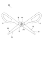
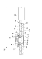
図10は、第4実施形態に係るはさみの閉じた状態における平面図である。図11は、第4実施形態に係るはさみの開いた状態における平面図である。図12は、図10のXII-XII線における断面図である。
図2に示す第1実施形態では、第1刃体10と第2刃体20とは、直接重ね合わされている。これに対して、図10から図12に示す第4実施形態では、第1刃体310と第2刃体20との間に、摺動部材370が設けられている点で、第1実施形態と異なっている。
次に第4実施形態のはさみ301について説明する。
図10は、第4実施形態に係るはさみの閉じた状態における平面図である。図11は、第4実施形態に係るはさみの開いた状態における平面図である。図12は、図10のXII-XII線における断面図である。
図2に示す第1実施形態では、第1刃体10と第2刃体20とは、直接重ね合わされている。これに対して、図10から図12に示す第4実施形態では、第1刃体310と第2刃体20との間に、摺動部材370が設けられている点で、第1実施形態と異なっている。
図10から図12に示すように、はさみ301は、摺動部材370を備えている。摺動部材370は、第1刃体310および第2刃体20の支持軸30よりも基端側であって、第1刃体310と第2刃体20とが常時対向する箇所に設けられている。摺動部材370は、軸方向から見て支持軸30を中心とする周方向に沿って延びるように形成されている。図12に示すように、摺動部材370は、第1刃体310の第1基体311の上面に形成された収容溝314内に配置されている。収容溝314は、摺動部材370の形状に対応して形成されている。摺動部材370の上面は、第2刃体20の第2基体21の下面に当接している。摺動部材370は、第1刃体310と第2刃体20とを互いに離間する方向に付勢している。
本実施形態によれば、第1刃体310と第2刃体20とが常時対向する箇所には、摺動部材370が設けられているので、第1刃体310と第2刃体20との摺動抵抗を低減することができる。したがって、第1刃体310と第2刃体20との動きを円滑にすることができる。
また、摺動部材370は、第1刃体310および第2刃体20の支持軸30よりも基端側に設けられ、第1刃体310と第2刃体20とを互いに離間する方向に付勢するので、支持軸30を支点にして第1刃体310および第2刃体20の先端側同士を互いに接近させることができる。これにより、第1刃体310および第2刃体20の先端側に設けられる刃線同士を常時圧接させることができ、切断性能を向上させることができる。
[第5実施形態]
次に第5実施形態のはさみ401について説明する。
図13は、第5実施形態に係るはさみの説明図であって、図10のXII-XII線に相当する部分における断面図である。
図12に示す第4実施形態では、すべり軸受40が軸方向に沿って一様に形成されている。これに対して、図13に示す第5実施形態では、すべり軸受440の外周面440a(規制部)が固定部材50側から第1刃体310側に向かうに従い漸次縮径している点で、第4実施形態と異なっている。また、図12に示す第4実施形態では、第2刃体20の軸受保持孔23が軸方向に一定の内径で貫通している。これに対して、図13に示す第5実施形態では、第2刃体420の軸受保持孔423の内周面423a(規制部)が固定部材50側から第1刃体310側に向かうに従い漸次縮径している点で、第4実施形態と異なっている。
次に第5実施形態のはさみ401について説明する。
図13は、第5実施形態に係るはさみの説明図であって、図10のXII-XII線に相当する部分における断面図である。
図12に示す第4実施形態では、すべり軸受40が軸方向に沿って一様に形成されている。これに対して、図13に示す第5実施形態では、すべり軸受440の外周面440a(規制部)が固定部材50側から第1刃体310側に向かうに従い漸次縮径している点で、第4実施形態と異なっている。また、図12に示す第4実施形態では、第2刃体20の軸受保持孔23が軸方向に一定の内径で貫通している。これに対して、図13に示す第5実施形態では、第2刃体420の軸受保持孔423の内周面423a(規制部)が固定部材50側から第1刃体310側に向かうに従い漸次縮径している点で、第4実施形態と異なっている。
図13に示すように、すべり軸受440の外周面440aは、固定部材50側から第1刃体310側に向かうに従い漸次縮径する傾斜面である。軸受保持孔423の内周面423aは、すべり軸受440の外周面440aに対応するように、固定部材50側から第1刃体310側に向かうに従い漸次縮径する傾斜面である。すべり軸受440の外周面440aおよび軸受保持孔423の内周面423aは、すべり軸受440の第2刃体420に対する第1刃体310側への移動を規制している。
このように、本実施形態によれば、付勢部材60によりすべり軸受440に作用する第1刃体310側への付勢力の一部を、すべり軸受440の外周面440aと軸受保持孔423の内周面423aとの接触箇所において、すべり軸受440の径方向の外側へ向けることができる。このため、すべり軸受440の外周面440aと軸受保持孔423の内周面423aとの間に、径方向の隙間が生じることを抑制できる。これにより、第2刃体420にがたつきが生じることが抑制されるので、第1刃体310と第2刃体420とを安定して圧接させることが可能となる。したがって、優れた切断性能を維持できるはさみ401を提供できる。
図14は、付勢部材の変形例を示す説明図であって、図10のXII-XII線に相当する部分における断面図である。
なお、上記第5実施形態においても、図9に示す第3実施形態の変形例と同様に、図14に示すように、例えばゴムやシリコンゴム、ウレタン等の弾性材料により形成された環状の付勢部材160を用いることができる。
なお、上記第5実施形態においても、図9に示す第3実施形態の変形例と同様に、図14に示すように、例えばゴムやシリコンゴム、ウレタン等の弾性材料により形成された環状の付勢部材160を用いることができる。
[第6実施形態]
次に第6実施形態のはさみ501について説明する。
図15は、第6実施形態に係るはさみの説明図であって、図10のXII-XII線に相当する部分における断面図である。
図13に示す第5実施形態では、すべり軸受440は1つの部材として構成されている。これに対して、図15に示す第6実施形態では、すべり軸受540は、第1軸受542と第2軸受543とを備えている点で、第5実施形態と異なっている。
次に第6実施形態のはさみ501について説明する。
図15は、第6実施形態に係るはさみの説明図であって、図10のXII-XII線に相当する部分における断面図である。
図13に示す第5実施形態では、すべり軸受440は1つの部材として構成されている。これに対して、図15に示す第6実施形態では、すべり軸受540は、第1軸受542と第2軸受543とを備えている点で、第5実施形態と異なっている。
図15に示すように、すべり軸受540は、第2刃体420に接触する第1軸受542と、第1軸受542と支持軸30との間に配置された第2軸受543と、を備えている。
第2軸受543には、支持軸30が摺動自在に挿通されている。第2軸受543は、例えば樹脂材料や金属材料等により円環状に形成されている。第2軸受543の外周面543aは、固定部材50側から第1刃体310側に向かうに従い漸次縮径する傾斜面とされている。第2軸受543は、付勢部材60により第1刃体310側に向かって付勢されている。
第2軸受543には、支持軸30が摺動自在に挿通されている。第2軸受543は、例えば樹脂材料や金属材料等により円環状に形成されている。第2軸受543の外周面543aは、固定部材50側から第1刃体310側に向かうに従い漸次縮径する傾斜面とされている。第2軸受543は、付勢部材60により第1刃体310側に向かって付勢されている。
第1軸受542は、例えば樹脂材料により円環状に形成されている。第1軸受542の内周面542aは、固定部材50側から第1刃体310側に向かうに従い漸次縮径する傾斜面である。第1軸受542の内周面542aは、第2軸受543の外周面543aに対応するように形成されている。第1軸受542の外周面542bは、固定部材50側から第1刃体310側に向かうに従い漸次縮径する傾斜面である。第1軸受542の外周面542bは、軸受保持孔423の内周面423aに対応するように形成されている。
このように、本実施形態によれば、すべり軸受540は、第2刃体420に接触する第1軸受542と、第1軸受542と支持軸30との間に配置される第2軸受543と、を備えているため、支持軸30に対して第2刃体420が回転する際に、付勢部材60による付勢により第2軸受543が支持軸30に対して回転し難くなった場合でも、第1軸受542を第2軸受543に対して回転させることができる。これにより、第1刃体310と第2刃体420との動きを円滑にすることができる。
この際、第2軸受543の外周面543aは、固定部材50側から第1刃体310側に向かうに従い漸次縮径しているため、第2軸受543の外周面543aと第1軸受542の内周面542aとの接触箇所において、第2軸受543に作用する付勢部材60の第1刃体310側への付勢力の一部を、径方向の外側へ向けることができる。このため、第1軸受542と第2軸受543との間に、径方向の隙間が生じることを抑制できる。したがって、第1軸受542および第2軸受543ががたつくことを抑制でき、第2刃体420にがたつきが生じることを抑制できる。
[第7実施形態]
次に第7実施形態のはさみ601について説明する。
図16は、第7実施形態に係るはさみの説明図であって、図10のXII-XII線に相当する部分における断面図である。
図15に示す第6実施形態では、第2軸受543は1つの部材として構成されている。これに対して、図16に示す第7実施形態では、第2軸受643は、外側部材644と内側部材645とを備えている点で、第6実施形態と異なっている。
次に第7実施形態のはさみ601について説明する。
図16は、第7実施形態に係るはさみの説明図であって、図10のXII-XII線に相当する部分における断面図である。
図15に示す第6実施形態では、第2軸受543は1つの部材として構成されている。これに対して、図16に示す第7実施形態では、第2軸受643は、外側部材644と内側部材645とを備えている点で、第6実施形態と異なっている。
図16に示すように、すべり軸受640は、第1軸受542と第2軸受643とを備えている。第2軸受643は、第1軸受542の内周面542aに接触する円環状の外側部材644と、外側部材644と支持軸30との間に配置された円環状の内側部材645と、を備えている。
内側部材645には、支持軸30が摺動自在に挿通されている。内側部材645は、例えば樹脂材料により形成されている。内側部材645の外周面645aは、固定部材50側から第1刃体310側に向かうに従い漸次縮径する傾斜面である。内側部材645は、付勢部材60により第1刃体310側に向かって付勢されている。
内側部材645には、支持軸30が摺動自在に挿通されている。内側部材645は、例えば樹脂材料により形成されている。内側部材645の外周面645aは、固定部材50側から第1刃体310側に向かうに従い漸次縮径する傾斜面である。内側部材645は、付勢部材60により第1刃体310側に向かって付勢されている。
外側部材644は、例えば金属材料等の第1軸受542および内側部材645と異なる材料により形成されている。外側部材644の内周面644aは、固定部材50側から第1刃体310側に向かうに従い漸次縮径する傾斜面である。外側部材644の内周面644aは、内側部材645の外周面645aに対応するように形成されている。外側部材644の外周面644bは、固定部材50側から第1刃体310側に向かうに従い漸次縮径する傾斜面である。外側部材644の外周面644bは、第1軸受542の内周面542aに対応するように形成されている。
このように、本実施形態によれば、第2軸受643は、第1軸受542の内周面542aに接触する円環状の外側部材644と、外側部材644と支持軸30との間に配置される円環状の内側部材645と、を備えているため、支持軸30に対して第2刃体420が回転する際に、付勢部材60による付勢により第2軸受643の内側部材645が支持軸30に対して回転し難くなった場合でも、第2軸受643の外側部材644および第1軸受542を第2軸受643の内側部材645に対して回転させることができる。これにより、第1刃体310と第2刃体420との動きを円滑にすることができる。
この際、第2軸受643の内側部材645の外周面645aは、固定部材50側から第1刃体310側に向かうに従い漸次縮径しているため、内側部材645の外周面645aと第2軸受643の外側部材644の内周面644aとの接触箇所において、第2軸受643の内側部材645に作用する付勢部材60の第1刃体310側への付勢力の一部を、径方向の外側へ向けることができる。このため、外側部材644と内側部材645との間に、径方向の隙間が生じることを抑制できる。したがって、外側部材644および内側部材645ががたつくことを抑制でき、第2刃体420にがたつきが生じることを抑制できる。
しかも、第2軸受643の外側部材644は、第1軸受542および第2軸受643の内側部材645とは異なる材料で形成されているので、外側部材644と第1軸受542との接触箇所、および外側部材644と内側部材645との接触箇所における摺動抵抗を低下させることができる。したがって、第1刃体310と第2刃体420との動きをより円滑にすることができる。
[第8実施形態]
次に第8実施形態のはさみ701について説明する。
図17は、第8実施形態に係るはさみの第1刃体の平面図である。図18は、第8実施形態に係るはさみの支持軸の平面図である。図19は、第8実施形態に係るはさみの支持軸の側面図である。
図3に示す第1実施形態では、支持軸挿通孔13は、横断面視で円形状に形成されている。これに対して、図17に示す第8実施形態では、支持軸挿通孔713が横断面視で非円形状(異形)に形成されている点で、第1実施形態と異なっている。また、図5に示す第1実施形態では、支持軸30の大径部31は、横断面視で円形状に形成されている。これに対して、図18に示す第6実施形態では、支持軸730の大径部731は、横断面視で非円形状(異形)に形成されている点で、第1実施形態と異なっている。
次に第8実施形態のはさみ701について説明する。
図17は、第8実施形態に係るはさみの第1刃体の平面図である。図18は、第8実施形態に係るはさみの支持軸の平面図である。図19は、第8実施形態に係るはさみの支持軸の側面図である。
図3に示す第1実施形態では、支持軸挿通孔13は、横断面視で円形状に形成されている。これに対して、図17に示す第8実施形態では、支持軸挿通孔713が横断面視で非円形状(異形)に形成されている点で、第1実施形態と異なっている。また、図5に示す第1実施形態では、支持軸30の大径部31は、横断面視で円形状に形成されている。これに対して、図18に示す第6実施形態では、支持軸730の大径部731は、横断面視で非円形状(異形)に形成されている点で、第1実施形態と異なっている。
図17に示すように、第1刃体710の第1基体711における支持軸挿通孔713の内周面には、互いに対向する一対の2方取り面713a(回り止め部)が形成されている。
図18および図19に示すように、支持軸730は、支持軸挿通孔713(図17参照)に嵌合される大径部731を備えている。大径部731は、円柱状に形成されており、軸方向に直交する所定径方向の両側に2方取り部731b(回り止め部)が形成されている。図17および図18に示すように、2方取り部731bは、支持軸挿通孔713の2方取り面713aに対応する形状に形成されている。これにより、2方取り面713aおよび2方取り部731bは、第1刃体710および支持軸730が相対回転できないようにしている。支持軸730は、第1刃体710に対して着脱可能であって、かつ相対回転不能とされた状態で圧入されている。
図18および図19に示すように、支持軸730は、支持軸挿通孔713(図17参照)に嵌合される大径部731を備えている。大径部731は、円柱状に形成されており、軸方向に直交する所定径方向の両側に2方取り部731b(回り止め部)が形成されている。図17および図18に示すように、2方取り部731bは、支持軸挿通孔713の2方取り面713aに対応する形状に形成されている。これにより、2方取り面713aおよび2方取り部731bは、第1刃体710および支持軸730が相対回転できないようにしている。支持軸730は、第1刃体710に対して着脱可能であって、かつ相対回転不能とされた状態で圧入されている。
本実施形態によれば、第1刃体710を支えた状態で支持軸730に固定部材50(図2参照)を装着する際に、第1刃体710および支持軸730が相対回転できないようにする2方取り面713aおよび2方取り部731bによって、支持軸730が第1刃体710に対して回転することを防止できる。したがって、固定部材50の支持軸730への着脱を容易に行うことが可能となり、第1刃体710および第2刃体20(図2参照)の分解や組み立てを容易に行うことができる。
なお、本実施形態では、支持軸挿通孔713および支持軸730を2方取り(2面取り)することにより、第1刃体710および支持軸730を、分解可能であって、かつ相対回転できないようにしているが、これに限定されるものではない。第1刃体と支持軸とは、互いに分解可能であって、かつ相対回転できなければよく、これらの連結箇所が軸方向から見て例えば多角形状等の非円形状に形成されていてもよい。また、第1刃体と支持軸とは、ピン等の回り止め部により相対回転できないようにされていてもよい。
[第9実施形態]
次に第9実施形態のはさみ801について説明する。
図20は、第9実施形態に係るはさみの説明図であって、図1のII-II線に相当する部分における断面図である。
図2に示す第1実施形態では、支持軸30の下端面は、平面状に形成されている。これに対して、図20に示す第9実施形態では、支持軸830の下端面(軸方向における第1刃体10側の端面)には、軸方向に直交する方向に沿って延びる溝部834が形成されている点で、第1実施形態と異なっている。
次に第9実施形態のはさみ801について説明する。
図20は、第9実施形態に係るはさみの説明図であって、図1のII-II線に相当する部分における断面図である。
図2に示す第1実施形態では、支持軸30の下端面は、平面状に形成されている。これに対して、図20に示す第9実施形態では、支持軸830の下端面(軸方向における第1刃体10側の端面)には、軸方向に直交する方向に沿って延びる溝部834が形成されている点で、第1実施形態と異なっている。
本実施形態によれば、支持軸830の下端面には、溝部834が形成されているため、溝部834にドライバ等を差し込んで支持軸830を固定することができる。これにより、固定部材50の支持軸830への着脱を容易に行うことが可能となり、第1刃体10および第2刃体20の分解や組み立てを容易に行うことができる。
なお、本発明は、図面を参照して説明した上述の実施形態に限定されるものではなく、その技術的範囲において様々な変形例が考えられる。
例えば、上記各実施形態においては、切断機の一例としてはさみを例に挙げて説明しているが、これに限定されず、切断機は例えば裁断機であってもよい。
例えば、上記各実施形態においては、切断機の一例としてはさみを例に挙げて説明しているが、これに限定されず、切断機は例えば裁断機であってもよい。
また、上記各実施形態では、固定部材は支持軸の上端部(雄ネジ部)に螺着されるナット部材であったが、これに限定されるものではない。図21に示すように、固定部材950は、支持軸930の上端部を座屈変形させたカシメ部であってもよい。
その他、本発明の趣旨を逸脱しない範囲で、上記した実施の形態における構成要素を周知の構成要素に置き換えることは適宜可能である。
上記各実施形態の切断機によれば、第2刃体は、支持軸にすべり軸受を介して回転自在に支持されるため、第1刃体と第2刃体との動きを円滑にすることができる。しかも、第2刃体およびすべり軸受のうち少なくともいずれか一方には、すべり軸受の第2刃体に対する第1刃体側への移動を規制する規制部が設けられている。このため、すべり軸受が付勢部材により第1刃体側に向かって付勢されることで、すべり軸受に作用する付勢部材の付勢力を第2刃体に作用させて、第2刃体を第1刃体に向かって押圧することができる。これにより、第1刃体と第2刃体とが常時圧接され、切断性能を維持することができる。また、この切断機を具備するはさみにおいても、同様の作用効果を得ることができる。
したがって、上記各実施形態によれば、優れた切断性能を維持できる切断機およびはさみを提供できるので、産業上の利用可能性は大である。
したがって、上記各実施形態によれば、優れた切断性能を維持できる切断機およびはさみを提供できるので、産業上の利用可能性は大である。
1,101,201,301,401,501,601,701,801 はさみ(切断機)
10,310,710 第1刃体
12 第1把持部
20,120,420 第2刃体
22 第2把持部
24 内フランジ部(規制部)
30,730,830,930 支持軸
40,140,440,540,640 すべり軸受
50,950 固定部材
60,160 付勢部材
60a 座面
61 スペーサ
141 外フランジ(規制部)
370 摺動部材
423 軸受保持孔
423a 軸受保持孔の内周面
542 第1軸受
542a 第1軸受の内周面
543,643 第2軸受
543a 第2軸受の外周面
644 外側部材
644a 外側部材の内周面
645 内側部材
645a 内側部材の外周面
713a 2方取り面(回り止め部)
731b 2方取り部(回り止め部)
834 溝部
10,310,710 第1刃体
12 第1把持部
20,120,420 第2刃体
22 第2把持部
24 内フランジ部(規制部)
30,730,830,930 支持軸
40,140,440,540,640 すべり軸受
50,950 固定部材
60,160 付勢部材
60a 座面
61 スペーサ
141 外フランジ(規制部)
370 摺動部材
423 軸受保持孔
423a 軸受保持孔の内周面
542 第1軸受
542a 第1軸受の内周面
543,643 第2軸受
543a 第2軸受の外周面
644 外側部材
644a 外側部材の内周面
645 内側部材
645a 内側部材の外周面
713a 2方取り面(回り止め部)
731b 2方取り部(回り止め部)
834 溝部
Claims (11)
- 支持軸と、
前記支持軸を保持する第1刃体と、
前記支持軸に装着されたすべり軸受と、
前記第1刃体に重ね合わさるように設けられ、かつ前記支持軸に前記すべり軸受を介して回転自在に支持された第2刃体と、
前記支持軸の前記すべり軸受を挟んで前記第1刃体とは反対側に配置された固定部材と、
前記すべり軸受と前記固定部材との間に配置された付勢部材と、
を備え、
前記第2刃体および前記すべり軸受のうち少なくともいずれか一方には、前記すべり軸受の前記第2刃体に対する前記第1刃体側への移動を規制する規制部が設けられ、
前記すべり軸受は、前記付勢部材により前記第1刃体側に向かって付勢されている切断機。 - 前記すべり軸受と前記付勢部材との間には、スペーサが介在している請求項1に記載の切断機。
- 前記付勢部材は、前記すべり軸受側に座面を有する請求項1または請求項2に記載の切断機。
- 前記すべり軸受の外周面は、前記固定部材側から前記第1刃体側に向かうに従い漸次縮径し、
前記第2刃体は、前記すべり軸受を保持する軸受保持孔を備え、
前記軸受保持孔は、前記すべり軸受の前記外周面に対応するように、前記固定部材側から前記第1刃体側に向かうに従い漸次縮径する内周面を備える、
請求項1から請求項3のいずれか1項に記載の切断機。 - 前記すべり軸受は、
前記第2刃体に接触する第1軸受と、
前記第1軸受と前記支持軸との間に配置され、前記支持軸が摺動自在に挿通されるとともに、前記付勢部材により前記第1刃体側に向かって付勢される第2軸受と、
を備え、
前記第2軸受の外周面は、前記固定部材側から前記第1刃体側に向かうに従い漸次縮径し、
前記第1軸受の内周面は、前記第2軸受の前記外周面に対応するように、前記固定部材側から前記第1刃体側に向かうに従い漸次縮径している、
請求項1から請求項4のいずれか1項に記載の切断機。 - 前記第2軸受は、
前記第1軸受の前記内周面に接触する円環状の外側部材と、
前記外側部材と前記支持軸との間に配置されるとともに、前記付勢部材により前記第1刃体側に向かって付勢される円環状の内側部材と、
を備え、
前記内側部材の外周面は、前記固定部材側から前記第1刃体側に向かうに従い漸次縮径し、
前記外側部材の内周面は、前記内側部材の前記外周面に対応するように、前記固定部材側から前記第1刃体側に向かうに従い漸次縮径している、
請求項5に記載の切断機。 - 前記第1刃体と前記第2刃体とが常時対向する箇所には、摺動部材が設けられている請求項1から請求項6のいずれか1項に記載の切断機。
- 前記摺動部材は、前記第1刃体および前記第2刃体の前記支持軸よりも基端側に設けられ、前記第1刃体と前記第2刃体とを互いに離間する方向に付勢する請求項7に記載の切断機。
- 前記第1刃体および前記支持軸の少なくとも一方には、前記第1刃体および前記支持軸が相対回転できないようにする回り止め部が設けられている請求項1から請求項8のいずれか1項に記載の切断機。
- 前記支持軸の軸方向における前記第1刃体側の端面には、溝部が形成されている請求項1から請求項9のいずれか1項に記載の切断機。
- 請求項1から請求項10のいずれか1項に記載の切断機と、
前記第1刃体の基端側に設けられた第1把持部と、
前記第2刃体の基端側に設けられた第2把持部と、
を備えるはさみ。
Priority Applications (3)
| Application Number | Priority Date | Filing Date | Title |
|---|---|---|---|
| DE112016003064.9T DE112016003064T5 (de) | 2015-07-06 | 2016-06-16 | Schneidvorrichtung und Schere |
| US15/579,541 US20180161994A1 (en) | 2015-07-06 | 2016-06-16 | Cutting device and scissors |
| CN201680032495.3A CN107614219B (zh) | 2015-07-06 | 2016-06-16 | 切断机和剪刀 |
Applications Claiming Priority (2)
| Application Number | Priority Date | Filing Date | Title |
|---|---|---|---|
| JP2015135496A JP6048772B1 (ja) | 2015-07-06 | 2015-07-06 | 切断機およびはさみ |
| JP2015-135496 | 2015-07-06 |
Publications (1)
| Publication Number | Publication Date |
|---|---|
| WO2017006734A1 true WO2017006734A1 (ja) | 2017-01-12 |
Family
ID=57572354
Family Applications (1)
| Application Number | Title | Priority Date | Filing Date |
|---|---|---|---|
| PCT/JP2016/067908 Ceased WO2017006734A1 (ja) | 2015-07-06 | 2016-06-16 | 切断機およびはさみ |
Country Status (5)
| Country | Link |
|---|---|
| US (1) | US20180161994A1 (ja) |
| JP (1) | JP6048772B1 (ja) |
| CN (1) | CN107614219B (ja) |
| DE (1) | DE112016003064T5 (ja) |
| WO (1) | WO2017006734A1 (ja) |
Families Citing this family (4)
| Publication number | Priority date | Publication date | Assignee | Title |
|---|---|---|---|---|
| JP6048771B1 (ja) * | 2015-07-06 | 2016-12-21 | セイコーインスツル株式会社 | 切断機およびはさみ |
| JP6048772B1 (ja) * | 2015-07-06 | 2016-12-21 | セイコーインスツル株式会社 | 切断機およびはさみ |
| CN110893625A (zh) * | 2018-09-13 | 2020-03-20 | 阳江市港富实业有限公司 | 剪刀 |
| JP6916557B1 (ja) * | 2020-10-26 | 2021-08-11 | 足立工業株式会社 | 理美容鋏 |
Citations (7)
| Publication number | Priority date | Publication date | Assignee | Title |
|---|---|---|---|---|
| JPS57139386A (en) * | 1981-02-23 | 1982-08-28 | Fukutarou Takahashi | Hair cut scissor for barber and beauty |
| JPH05154259A (ja) * | 1991-05-28 | 1993-06-22 | “ヤグアール”・シユタールウアーレンフアブリーク・ゲゼルシヤフト・ミト・ベシユレンクテル・ハフツング・ウント・コンパニー・コマンデイトゲゼルシヤフト | 鋏 |
| JPH0563467U (ja) * | 1992-02-05 | 1993-08-24 | 丸章工業株式会社 | 鋏における開閉中心軸部の構造 |
| JPH11244551A (ja) * | 1998-02-27 | 1999-09-14 | Tokosha:Kk | 鋏 |
| JP2000510358A (ja) * | 1996-04-13 | 2000-08-15 | “ヤグアール”・シュタールウアーレンファブリーク・ゲゼルシャフト・ミト・ベシュレンクテル・ハフツング・ウント・コンパニー・コマンディトゲゼルシャフト | はさみ |
| US20010002514A1 (en) * | 1996-10-16 | 2001-06-07 | Steffen Homann | Heatable cutting instrument, specially scissors, knife, clippers or the like |
| JP2006314745A (ja) * | 2005-05-11 | 2006-11-24 | Kawashima Seikyosho:Kk | 理美容鋏 |
Family Cites Families (28)
| Publication number | Priority date | Publication date | Assignee | Title |
|---|---|---|---|---|
| US174846A (en) * | 1876-03-14 | Improvement in shears | ||
| US946441A (en) * | 1909-04-27 | 1910-01-11 | Frank O Homme | Scissors. |
| US981436A (en) * | 1909-11-30 | 1911-01-10 | Ellis S G Lewis | Shears. |
| US2600036A (en) * | 1948-10-04 | 1952-06-10 | Stanley A Wertepny | Pinking shears |
| US2645850A (en) * | 1949-08-04 | 1953-07-21 | Acme Shear Company | Scissors pivot structure |
| US2741844A (en) * | 1954-11-29 | 1956-04-17 | Acme Shear Company | Pivot connection for the blades of scissors or shears |
| US3170237A (en) * | 1962-12-03 | 1965-02-23 | Samuel Briskman | Pinking shears |
| US3611570A (en) * | 1969-04-24 | 1971-10-12 | I Marco Levi Laurenti | Adjustable scissors and shears with hand dial regulator |
| US3672053A (en) * | 1971-02-26 | 1972-06-27 | Wiss & Sons Co J | Pivot arrangement |
| US4104794A (en) * | 1977-08-15 | 1978-08-08 | The Raymond Lee Organization, Inc. | Scissors |
| FI58732C (fi) * | 1979-09-28 | 1981-04-10 | Fiskars Ab Oy | Anordning vid sax foer utjaemning av saxens slutningskraft |
| US5440813A (en) * | 1993-06-04 | 1995-08-15 | Roskam; Scott H. | Rideless scissors with an adjustable load transverse to the pivot axis on a pivot joint |
| JPH07236778A (ja) * | 1994-03-01 | 1995-09-12 | Yoshio Ebi | 理美容用はさみ |
| CH687829A5 (fr) * | 1994-05-04 | 1997-02-28 | Maurice Petignat | Dispositif d'assemblage de deux éléments l'un à l'autre. |
| JP2659685B2 (ja) * | 1994-06-17 | 1997-09-30 | 株式会社ナルト | はさみ |
| JPH0938348A (ja) * | 1995-08-02 | 1997-02-10 | Shintaro Okamiya | 理髪用鋏における枢着部の構造 |
| JP3013231B2 (ja) * | 1995-11-02 | 2000-02-28 | 新太郎 岡宮 | 理髪用鋏における枢着部の構造 |
| US6418626B1 (en) * | 2000-10-30 | 2002-07-16 | Ming-Shan Jang | Pruning shears with a lock device |
| DE10310259A1 (de) * | 2003-03-05 | 2004-09-23 | Bessey & Sohn Gmbh & Co. Kg | Durchlaufschere |
| CN2635297Y (zh) * | 2003-08-11 | 2004-08-25 | 赵合 | 滚子结构剪刀 |
| CN2663098Y (zh) * | 2003-12-23 | 2004-12-15 | 得堡士有限公司 | 改进的纱剪 |
| US20050193569A1 (en) * | 2004-03-08 | 2005-09-08 | Double C. Limited | Scissors |
| US20070124942A1 (en) * | 2005-12-07 | 2007-06-07 | Nenadich Stephen M | Ball bearing tension system for a shear |
| CN202062389U (zh) * | 2011-02-28 | 2011-12-07 | 深圳心雷工业设计有限公司 | 一种转轴可滑动的剪刀 |
| CN202336881U (zh) * | 2011-11-14 | 2012-07-18 | 陈品格 | 一种新型裁缝剪 |
| WO2014167766A1 (ja) * | 2013-04-11 | 2014-10-16 | 株式会社柳生 | 鋏の枢軸構造 |
| JP6048771B1 (ja) * | 2015-07-06 | 2016-12-21 | セイコーインスツル株式会社 | 切断機およびはさみ |
| JP6048772B1 (ja) * | 2015-07-06 | 2016-12-21 | セイコーインスツル株式会社 | 切断機およびはさみ |
-
2015
- 2015-07-06 JP JP2015135496A patent/JP6048772B1/ja not_active Expired - Fee Related
-
2016
- 2016-06-16 WO PCT/JP2016/067908 patent/WO2017006734A1/ja not_active Ceased
- 2016-06-16 US US15/579,541 patent/US20180161994A1/en not_active Abandoned
- 2016-06-16 CN CN201680032495.3A patent/CN107614219B/zh not_active Expired - Fee Related
- 2016-06-16 DE DE112016003064.9T patent/DE112016003064T5/de not_active Ceased
Patent Citations (7)
| Publication number | Priority date | Publication date | Assignee | Title |
|---|---|---|---|---|
| JPS57139386A (en) * | 1981-02-23 | 1982-08-28 | Fukutarou Takahashi | Hair cut scissor for barber and beauty |
| JPH05154259A (ja) * | 1991-05-28 | 1993-06-22 | “ヤグアール”・シユタールウアーレンフアブリーク・ゲゼルシヤフト・ミト・ベシユレンクテル・ハフツング・ウント・コンパニー・コマンデイトゲゼルシヤフト | 鋏 |
| JPH0563467U (ja) * | 1992-02-05 | 1993-08-24 | 丸章工業株式会社 | 鋏における開閉中心軸部の構造 |
| JP2000510358A (ja) * | 1996-04-13 | 2000-08-15 | “ヤグアール”・シュタールウアーレンファブリーク・ゲゼルシャフト・ミト・ベシュレンクテル・ハフツング・ウント・コンパニー・コマンディトゲゼルシャフト | はさみ |
| US20010002514A1 (en) * | 1996-10-16 | 2001-06-07 | Steffen Homann | Heatable cutting instrument, specially scissors, knife, clippers or the like |
| JPH11244551A (ja) * | 1998-02-27 | 1999-09-14 | Tokosha:Kk | 鋏 |
| JP2006314745A (ja) * | 2005-05-11 | 2006-11-24 | Kawashima Seikyosho:Kk | 理美容鋏 |
Also Published As
| Publication number | Publication date |
|---|---|
| CN107614219A (zh) | 2018-01-19 |
| JP2017012673A (ja) | 2017-01-19 |
| JP6048772B1 (ja) | 2016-12-21 |
| US20180161994A1 (en) | 2018-06-14 |
| CN107614219B (zh) | 2019-07-23 |
| DE112016003064T5 (de) | 2018-03-22 |
Similar Documents
| Publication | Publication Date | Title |
|---|---|---|
| WO2017006734A1 (ja) | 切断機およびはさみ | |
| JP4618450B2 (ja) | アクセル装置 | |
| WO2014045790A1 (ja) | フューエルリッドの支持構造 | |
| CN104583653B (zh) | 密封装置 | |
| WO2017018168A1 (ja) | ボールジョイント用ダストカバー | |
| WO2017006736A1 (ja) | 切断機およびはさみ | |
| WO2010041543A1 (ja) | 密封装置 | |
| EP1630431B1 (en) | Ball joint | |
| JP2018538496A5 (ja) | ||
| CN108291573B (zh) | 球窝接头用防尘罩以及球窝接头用防尘罩的安装方法 | |
| JP6866864B2 (ja) | リミットスイッチ | |
| JP2015028347A (ja) | バルブおよびバルブ用アタッチメント | |
| CN100557253C (zh) | 具有法兰型盘簧的铰接装置 | |
| JP2006300204A (ja) | ボールジョイント | |
| JP2001336523A (ja) | ヒンジ用摩擦板およびヒンジ | |
| JP2016125625A (ja) | ダストカバー | |
| JP5066787B2 (ja) | 密封構造 | |
| KR20190049453A (ko) | 시일 기구를 구비하는 장치 | |
| JP5116384B2 (ja) | ヒンジブラケット | |
| JP4875560B2 (ja) | キャビネット用ステー及びそれを用いたキャビネット | |
| CN108691883B (zh) | 球窝接头的密封构件以及球窝接头 | |
| JP2006292094A (ja) | ボールジョイント及びそのベアリングシート | |
| JP3186509U (ja) | バルブおよびバルブ用アタッチメント | |
| JP3174559U (ja) | パッキンの装着構造 | |
| JP2007292229A (ja) | 軸受潤滑装置 |
Legal Events
| Date | Code | Title | Description |
|---|---|---|---|
| 121 | Ep: the epo has been informed by wipo that ep was designated in this application |
Ref document number: 16821204 Country of ref document: EP Kind code of ref document: A1 |
|
| WWE | Wipo information: entry into national phase |
Ref document number: 15579541 Country of ref document: US |
|
| WWE | Wipo information: entry into national phase |
Ref document number: 112016003064 Country of ref document: DE |
|
| 122 | Ep: pct application non-entry in european phase |
Ref document number: 16821204 Country of ref document: EP Kind code of ref document: A1 |