WO2017006722A1 - 鞍乗型車両用制御装置及び鞍乗型車両 - Google Patents
鞍乗型車両用制御装置及び鞍乗型車両 Download PDFInfo
- Publication number
- WO2017006722A1 WO2017006722A1 PCT/JP2016/067682 JP2016067682W WO2017006722A1 WO 2017006722 A1 WO2017006722 A1 WO 2017006722A1 JP 2016067682 W JP2016067682 W JP 2016067682W WO 2017006722 A1 WO2017006722 A1 WO 2017006722A1
- Authority
- WO
- WIPO (PCT)
- Prior art keywords
- brake
- type vehicle
- brake pressure
- force
- saddle riding
- Prior art date
Links
Images


Classifications
-
- B—PERFORMING OPERATIONS; TRANSPORTING
- B60—VEHICLES IN GENERAL
- B60T—VEHICLE BRAKE CONTROL SYSTEMS OR PARTS THEREOF; BRAKE CONTROL SYSTEMS OR PARTS THEREOF, IN GENERAL; ARRANGEMENT OF BRAKING ELEMENTS ON VEHICLES IN GENERAL; PORTABLE DEVICES FOR PREVENTING UNWANTED MOVEMENT OF VEHICLES; VEHICLE MODIFICATIONS TO FACILITATE COOLING OF BRAKES
- B60T8/00—Arrangements for adjusting wheel-braking force to meet varying vehicular or ground-surface conditions, e.g. limiting or varying distribution of braking force
- B60T8/17—Using electrical or electronic regulation means to control braking
- B60T8/1701—Braking or traction control means specially adapted for particular types of vehicles
- B60T8/1706—Braking or traction control means specially adapted for particular types of vehicles for single-track vehicles, e.g. motorcycles
-
- B—PERFORMING OPERATIONS; TRANSPORTING
- B60—VEHICLES IN GENERAL
- B60T—VEHICLE BRAKE CONTROL SYSTEMS OR PARTS THEREOF; BRAKE CONTROL SYSTEMS OR PARTS THEREOF, IN GENERAL; ARRANGEMENT OF BRAKING ELEMENTS ON VEHICLES IN GENERAL; PORTABLE DEVICES FOR PREVENTING UNWANTED MOVEMENT OF VEHICLES; VEHICLE MODIFICATIONS TO FACILITATE COOLING OF BRAKES
- B60T7/00—Brake-action initiating means
- B60T7/12—Brake-action initiating means for automatic initiation; for initiation not subject to will of driver or passenger
-
- B—PERFORMING OPERATIONS; TRANSPORTING
- B62—LAND VEHICLES FOR TRAVELLING OTHERWISE THAN ON RAILS
- B62L—BRAKES SPECIALLY ADAPTED FOR CYCLES
- B62L3/00—Brake-actuating mechanisms; Arrangements thereof
-
- B—PERFORMING OPERATIONS; TRANSPORTING
- B60—VEHICLES IN GENERAL
- B60T—VEHICLE BRAKE CONTROL SYSTEMS OR PARTS THEREOF; BRAKE CONTROL SYSTEMS OR PARTS THEREOF, IN GENERAL; ARRANGEMENT OF BRAKING ELEMENTS ON VEHICLES IN GENERAL; PORTABLE DEVICES FOR PREVENTING UNWANTED MOVEMENT OF VEHICLES; VEHICLE MODIFICATIONS TO FACILITATE COOLING OF BRAKES
- B60T2201/00—Particular use of vehicle brake systems; Special systems using also the brakes; Special software modules within the brake system controller
- B60T2201/06—Hill holder; Start aid systems on inclined road
Definitions
- the present invention relates to a straddle-type vehicle control device and a straddle-type vehicle.
- Patent Document 1 discloses a hill start assistance brake device for a motorcycle as an example of a conventional straddle-type vehicle control device.
- the motorcycle slope start assist brake device detects the stop of the vehicle when the vehicle is stopped, and detects the release of the brake input by the driver.
- the brake device then calculates the total braking force of the vehicle when the driver releases the brake input.
- the brake device further calculates the braking force required to maintain the vehicle stopped.
- the brake device determines whether or not the vehicle can be stopped with the calculated total braking force. When it is determined that the vehicle cannot be stopped, the brake device increases the total braking force of the vehicle.
- the brake device disclosed in Patent Document 1 the braking force necessary to maintain the braking pressure corresponding to the stop state on the slope or the like without the operation of the driver is maintained by the slope start support control function. Can do.
- the brake device disclosed in Patent Document 1 determines whether or not the driver intends to start based on the engine speed, wheel speed, or the like, and releases the brake pressure when it is determined that the driver intends to start.
- the slope start support control function is canceled based on the engine speed, wheel speed, and the like, and the vehicle can be started.
- the saddle riding type vehicle may not be started smoothly at the vehicle start timing expected by the driver.
- the driver when the start of the saddle riding type vehicle does not appropriately follow the driver's intention to start, the driver sometimes feels caught with respect to the start of the saddle riding type vehicle.
- the present invention provides a straddle-type vehicle control that assists the stability of the straddle-type vehicle when starting on an inclined ground and the like, and makes it possible to perform a smooth start while suppressing the driver from feeling caught.
- An apparatus and a saddle riding type vehicle are provided.
- the present invention adopts the following configuration in order to solve the above-described problems.
- the brake device operates when the driver does not perform the brake operation (hereinafter also referred to as “the brake is not operated”).
- the brake pressure of the brake device substantially follows the decrease in the brake force in the process in which the brake force becomes zero from the state in which the brake device is operated without performing the brake operation. Decrease. Therefore, in the present invention, in the process in which the braking force becomes zero from the state where the brake device is operated without performing the brake operation, while securing the brake capacity determined according to the brake pressure to the extent necessary for stopping the vehicle, An increase in the difference between the brake capacity and the braking force can be suppressed.
- the straddle-type vehicle control device of the present invention it is possible to assist the stability of the straddle-type vehicle when starting on an inclined ground and the like, and to suppress the driver from feeling caught. However, it is possible to make a smooth start.
- the brake pressure control unit is configured such that when the saddle riding type vehicle is started, the brake force is reduced in a process in which the brake force of the brake device becomes zero from a state where the brake device is operated without performing the brake operation.
- the brake pressure of the brake device is controlled so that the brake pressure of the brake device decreases when the brake force decreases and the brake pressure of the brake device increases when the brake force increases.
- the brake pressure control unit is configured to reduce the braking force in a process in which the braking force of the braking device becomes zero from a state where the braking device is operated without performing the braking operation when the saddle riding type vehicle starts.
- the brake pressure of the brake device is controlled so that the decrease of the brake pressure starts when the decrease starts.
- the brake pressure starts to decrease when the brake force starts to decrease, so that the difference between the brake capacity and the brake force is reduced while ensuring the brake capacity necessary for stopping the vehicle. can do. Therefore, it is possible to perform a smooth start while further suppressing the driver from feeling caught.
- the control device further includes: A brake pressure acquisition unit configured to obtain a brake pressure before stopping when the saddle riding type vehicle stops by braking; A stop-time brake pressure setting unit configured to set a brake pressure for stopping the straddle-type vehicle based on at least the brake pressure before the stop obtained by the brake pressure acquisition unit; The brake control unit is configured to operate the brake device of the straddle-type vehicle based on the brake pressure set by the stop-time brake pressure setting unit when the driver does not perform a brake operation. Has been.
- the brake pressure of the brake device that operates when the driver does not perform the brake operation is set based on the brake pressure before stopping when the saddle riding type vehicle stops by braking.
- the brake pressure before stopping reflects the state (for example, friction coefficient ⁇ ) of the brake device of the saddle type vehicle at that time. Therefore, according to the configuration of (4), the brake pressure of the brake device that operates when the brake is not operated can be set appropriately. Thereby, it can be suppressed that the brake pressure of the brake device that operates when the brake is not operated becomes excessively larger than the brake pressure necessary for maintaining the saddle riding type vehicle to stop. Therefore, the driver can further suppress the feeling of being caught.
- a straddle-type vehicle is Wheels of the saddle type vehicle; Any one of the control devices of (1) to (4); And a brake device operated by a brake control unit of the control device.
- the saddle riding type vehicle of (5) can assist the stability of the saddle riding type vehicle when starting on an inclined ground, etc., and perform a smooth start while suppressing the driver from feeling caught. Is possible.
- the stability of the saddle riding type vehicle is assisted when starting on an inclined ground and the like, and the driver is prevented from feeling caught. It is possible to make a fresh start.
- FIG. 1 is a side view showing a motorcycle on which a straddle-type vehicle control device according to a first embodiment of the present invention is mounted.
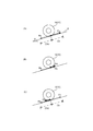
- A is the 1st schematic diagram explaining the force which acts on the saddle-riding type vehicle on an inclined land.
- B is the 2nd schematic diagram explaining the force which acts on the straddle-type vehicle on an inclined ground.
- C is the 3rd schematic diagram explaining the force which acts on the straddle-type vehicle on an inclined ground.
- It is a block diagram which shows the structure of an engine control apparatus and a hill assist control apparatus. It is a flowchart which shows a hill assist implementation determination process. It is a flowchart which shows a hill assist process.
- FIG. It is a flowchart which shows the brake pressure command value calculation process shown in FIG. It is a flowchart which shows the engine correction command value calculation process shown in FIG. It is a flowchart which shows the command value update process shown in FIG.
- A) is a graph which shows the change of the force which acts on the straddle-type vehicle which starts on the slope in this embodiment.
- B) is a graph which shows the change of the force which acts in a comparative example.
- ⁇ Saddle-type vehicles have higher mobility than ordinary automobiles.
- a brake device In a saddle riding type vehicle, frequent acceleration / deceleration is likely to be performed. Therefore, in a straddle-type vehicle, a brake device is generally used frequently, and a brake member (for example, a disc rotor, a brake pad, etc.) provided in the brake device is easily heated by friction.
- a brake member for example, a disc rotor, a brake pad, etc.
- the brake member is easily cooled, but is easily exposed to rain water, muddy water, and the like.
- the friction coefficient of the brake member is likely to change due to the influence of such temperature and surface condition. As the coefficient of friction changes, the brake capacity changes. That is, the brake capacity changes depending on the traveling state and environment of the saddle riding type vehicle.
- the inventors of the present application further studied.
- the brake pressure of the brake device in the process in which the brake force of the brake device becomes zero from the state where the brake device is operated without performing the brake operation. It has been conceived that the brake pressure of the brake device is controlled so as to substantially decrease following the decrease of the braking force. Thereby, it is possible to suppress an increase in the difference between the brake capacity and the brake force while securing the brake capacity necessary for stopping the vehicle. As a result, the start of the straddle-type vehicle can be easily followed by the driver's intention to start, and the driver can be prevented from being caught and feeling a sudden torque change.
- FIG. 1 is a side view showing a motorcycle equipped with a straddle-type vehicle control device according to a first embodiment of the present invention.
- a straddle-type vehicle 10 shown in FIG. 1 is a motorcycle.
- the saddle riding type vehicle 10 includes a vehicle body 11 and two wheels 12.
- the wheel 12 is rotatably supported by the vehicle body 11.
- the vehicle body 11 includes an engine 13, a transmission mechanism 14, and a brake device 15.
- the transmission mechanism 14 includes a clutch 14a, a transmission 14b, and a chain 14c.
- the driving force output from the engine 13 is transmitted to the rear wheel 12 via the transmission mechanism 14 including the clutch 14a.
- the brake device 15 is a friction brake that generates a braking force on the wheel 12 by a frictional force.
- the brake device 15 is constituted by a disc brake.
- the brake device 15 has a brake pad 15a that operates with the hydraulic pressure of the hydraulic fluid.
- the brake device 15 presses the brake pad 15 a against the disc rotor 12 a that rotates together with the wheel 12.
- the brake device 15 generates a braking force by friction between the brake pad 15a and the disc rotor 12a.
- the brake device 15 brakes the saddle riding type vehicle 10 by generating a braking force on the wheel 12.
- the saddle riding type vehicle 10 decelerates or stops by braking. Further, when the straddle-type vehicle 10 is on, for example, a slope, the braking force opposes the force applied to the straddle-type vehicle 10 on the slope. Thereby, the saddle riding type vehicle 10 can maintain the stop state.
- the engine 13 is provided with an engine rotation sensor 13 a that detects the rotation speed of the engine 13.
- the engine rotation sensor 13 a outputs a signal corresponding to the rotation speed of the engine 13.
- the saddle riding type vehicle 10 includes a vehicle speed sensor 11a, a load sensor 11c, an accelerator operation unit 16, a brake operation unit 17, a clutch operation unit 18, an engine control device 20, a hill assist control device 30, and a brake pressure adjustment device 40. Yes.
- the vehicle speed sensor 11 a detects the speed of the saddle riding type vehicle 10 by detecting the rotational speed of the wheel 12.
- the vehicle speed sensor 11 a outputs a signal corresponding to the speed of the saddle riding type vehicle 10.
- the load sensor 11 c detects a load applied to the saddle riding type vehicle 10.
- the load sensor 11c includes, for example, a 6-axis sensor having a 3-axis acceleration sensor and a 3-axis gyro sensor.
- the accelerator operation unit 16, the brake operation unit 17, and the clutch operation unit 18 are operated by the driver.
- the engine control device 20 controls the output of the engine 13 based on the operation of the accelerator operation unit 16.
- the engine control device 20 controls the output of the engine 13 by, for example, changing the ignition timing, intake air amount, and intake fuel of the engine 13.
- the clutch operation unit 18 controls the operation of the clutch 14a.
- Each of the accelerator operation unit 16, the brake operation unit 17, and the clutch operation unit 18 is provided with a sensor (not shown) that detects the operation.
- the accelerator operation unit 16, the brake operation unit 17, and the clutch operation unit 18 output a signal representing the operation amount to the hill assist control device 30 via sensors provided in each.
- the brake pressure adjusting device 40 adjusts the braking force generated in the brake device 15 based on the operation of the brake operation unit 17 and the command value from the hill assist control device 30.
- the brake pressure adjusting device 40 supplies the brake device 15 with the hydraulic pressure output from the brake operation unit 17 in accordance with the driver's operation.
- the brake device 15 operates with the brake pressure output from the brake pressure adjusting device 40.
- the brake pressure is a pressure at which the brake pad 15a is pressed against the disc rotor 12a.
- the brake pad 15 a of the brake device 15 is pressed against the disc rotor 12 a of the wheel 12 with a brake pressure corresponding to the hydraulic pressure output from the brake pressure adjusting device 40.
- the brake pressure adjusting device 40 has a hydraulic pump and a valve (not shown).
- the brake pressure adjusting device 40 can supply the brake device 15 with a hydraulic pressure higher than the hydraulic pressure output from the brake operation unit 17 by the operation of the hydraulic pump. Further, the brake pressure adjusting device 40 can operate the brake device 15 when the brake is not operated.
- the brake pressure adjusting device 40 provided in the brake device 15 of the present embodiment operates the brake device 15 with a brake pressure corresponding to the command value of the brake pressure from the hill assist control device 30.
- the brake pressure adjusting device 40 includes a sensor (not shown) that detects the brake pressure. Specifically, the hydraulic pressure sensor of the brake pressure adjusting device 40 outputs a signal corresponding to the hydraulic pressure. Since the hydraulic pressure of the hydraulic fluid corresponds to the brake pressure generated at the brake pad 15a, the brake pressure is obtained based on the signal from the brake pressure adjusting device 40.
- the hill assist control device 30 controls the brake pressure adjusting device 40.
- the hill assist control device 30 controls the brake pressure adjusting device 40 based on the operation of the brake operation unit 17 and the accelerator operation unit 16.
- the hill assist control device 30 controls the brake pressure adjusting device 40 and the brake device 15 so as to assist the starting operation of the saddle riding type vehicle 10 on the slope.
- the function of controlling the brake device 15 that assists the starting operation of the saddle riding type vehicle 10 on the slope is called hill assist.
- the saddle riding type vehicle 10 is provided with a hill assist switch 19.
- the hill assist switch 19 is operated by the driver to switch whether or not the hill assist mode is operable.
- the hill assist control device 30 of the present embodiment can also have an anti-lock braking system (ABS) control function.
- ABS anti-lock braking system
- the engine control device 20, the hill assist control device 30, and the brake pressure adjustment device 40 constitute a straddle-type vehicle control device.
- the engine control device 20 and the hill assist control device 30 are respectively provided with a central processing unit and a storage device (not shown).
- the storage device stores a program executed by the central processing unit, data used by the central processing unit for calculation, and data obtained as a result of the calculation.
- the engine control device 20 and the hill assist control device 30 may be shared by one piece of hardware.
- the hill assist control device 30 controls the brake pressure adjusting device 40 and the brake device 15 so as to assist the starting operation of the saddle riding type vehicle 10 on the slope.
- FIG. 2 (A) to FIG. 2 (C) are schematic diagrams for explaining the force acting on the saddle riding type vehicle 10 on an inclined land.
- the force acting on the saddle riding type vehicle 10 is represented as the force acting on one wheel 12.
- the saddle riding type vehicle 10 is stopped with the front of the saddle riding type vehicle 10 facing the upper part of the slope S. That is, the saddle riding type vehicle 10 is stopped on the uphill.
- the magnitude of the gradient resistance Rs corresponds to the total weight m of the saddle riding type vehicle 10 and the gradient ⁇ of the slope.
- the gradient resistance Rs increases as the total weight m increases.
- the gradient resistance Rs increases as the gradient ⁇ of the sloped land increases.
- the magnitude of the gradient resistance Rs does not change even if the braking force or driving force of the saddle riding type vehicle 10 changes.
- a braking force Fb is applied to the saddle riding type vehicle 10 that is stopped on an inclined ground.
- the brake device 15 (see FIG. 1) of the saddle riding type vehicle 10 causes the braking force Fb to act on the saddle riding type vehicle 10.
- the braking force Fb is generated as a reaction force of a force other than the braking force Fb that acts on the saddle riding type vehicle 10.
- the brake force Fb fluctuates according to fluctuations of other forces acting on the saddle riding type vehicle 10.
- the braking force Fb is balanced with the gradient resistance Rs. As a result, the saddle riding type vehicle 10 is stopped.
- the brake force Fb varies within a certain range corresponding to the brake pressure.
- the upper limit of the magnitude of the brake force that can be output by the brake device 15 at a given brake pressure is referred to as a brake capacity Cb.
- the brake force Fb and the brake capacity Cb are different physical quantities.
- the brake capacity Cb represents the ability of the braking force that can be output by the brake device 15 at a given brake pressure.
- the brake capacity Cb represents the maximum brake force that can be output by the brake device 15 at a given brake pressure.
- the brake capacity Cb is an upper limit for the magnitude of the braking force. For this reason, in FIG. 2A, the brake capacity Cb is displayed on both the front and rear sides where the brake force Fb can be generated.
- the brake capacity which is the upper limit of the magnitude of the braking force facing rearward of the saddle riding type vehicle 10, is indicated by “(Cb)” in FIG.
- the brake capacity Cb is due to the frictional force of the brake device 15.
- the brake capacity Cb is based on the principle of Coulomb friction.
- the brake capacity Cb depends on the brake pressure Pb at which the brake device 15 operates.
- the brake capacity Cb is expressed by the following equation, for example.
- ⁇ friction coefficient between the brake pad 15a and the disc rotor 12a
- Pb brake pressure
- the brake capacity Cb is substantially proportional to the brake pressure Pb.
- the brake force Fb is a force actually generated in the brake device 15.
- the brake force Fb is substantially equal to the brake capacity Cb.
- the brake force Fb is substantially equal to or less than the brake capacity Cb.
- the brake force Fb is usually smaller than the brake capacity Cb. For example, in a situation where neither the gradient resistance nor the driving force is applied to the saddle riding type vehicle 10 stopped at a substantially horizontal place, when the brake device 15 operates with the brake pressure Pb, the brake corresponding to the brake pressure Pb is applied. A capacitance Cb is generated.
- the brake capacity Cb becomes a value other than zero. At this time, no braking force Fb is generated. This is because the braking force Fb at the time of stop is generated as a reaction force (reaction) with respect to a force for moving the straddle-type vehicle 10 that is stopped.
- the driving force Fd is generated by operating the accelerator operation unit 16 at the time of departure.
- FIG. 2B shows a state where the driving force Fd is applied to the saddle riding type vehicle 10.
- the driving force Fd is a force for moving the saddle type vehicle 10 forward.
- the driving force Fd acts in a direction parallel to the ground on the sloping ground.
- the driving force Fd is a force toward the top of the hill.
- the driving force Fd is a force opposite to the gradient resistance Rs.
- the driving force Fd is increased by operating the accelerator operation unit 16 (see FIG. 1)
- the braking force Fb is decreased. While the vehicle is stopped, the braking force Fb decreases as the driving force Fd increases. This is because the braking force Fb while the vehicle is stopped is a reaction force against the combined force of the driving force Fd and the gradient resistance Rs.
- the direction of the braking force Fb becomes opposite to the direction of the driving force Fd as shown in FIG. This is because the braking force Fb is a reaction force against the combined force of the driving force Fd and the gradient resistance Rs.
- the braking force Fb acts in the rear direction of the saddle riding type vehicle 10.
- the braking force Fb increases as the driving force Fd increases.
- the magnitude of the brake force Fb increases to the brake capacity (Cb).
- the braking force Fb acts so as to prevent the start of the saddle riding type vehicle 10 by the driving force Fd. For this reason, even if the magnitude of the driving force Fd exceeds the magnitude of the gradient resistance Rs, the saddle riding type vehicle 10 does not start.
- the magnitude of the brake force Fb does not exceed the brake capacity (Cb). Accordingly, as a result of the increase in the driving force Fd, when the driving force Fd exceeds the sum of the brake capacity (Cb) and the gradient resistance Rs, the balance of the force can be solved. As a result, the saddle riding type vehicle 10 starts. In other words, the straddle-type vehicle 10 does not start until the driving force Fd exceeds the sum of the brake capacity (Cb) and the gradient resistance Rs. That is, the start is prevented by the brake force Fb. As a result, the driver feels caught.
- the engine control device 20 and the hill assist control device 30 shown in FIG. 1 set a brake pressure for stopping the saddle riding type vehicle 10 when the saddle riding type vehicle 10 stops on the slope S.
- the brake pressure for stopping the saddle riding type vehicle 10 is a brake pressure that can maintain the stopping state of the saddle riding type vehicle 10 on the slope S.
- the hill assist control device 30 activates the brake device 15 of the saddle riding type vehicle based on the set brake pressure when the saddle riding type vehicle 10 stops at the slope S and the driver does not perform the brake operation. Let The engine control device 20 and the hill assist control device 30 can assist the stability of the saddle riding type vehicle 10 when starting on an inclined ground.
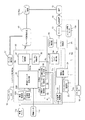
- FIG. 3 is a block diagram illustrating configurations of the engine control device 20 and the hill assist control device 30.
- FIG. 3 also shows devices connected to the engine control device 20 and the hill assist control device 30.
- a double line connecting each block shown in FIG. 3 represents a physical quantity or a physical action.
- a single line represents the flow of data representing each value.
- the processing of values such as force and pressure may be simply described by omitting “value” and processing “pressure” and “force”.
- the hill assist control device 30 includes a stop-time brake pressure setting unit 33, a friction coefficient acquisition unit 36, a brake control unit 37, and a brake pressure control unit 39. Each unit of the hill assist control device 30 is realized by a central processing unit (not shown) that executes a program.
- the friction coefficient acquisition unit 36 calculates an estimated value of the friction coefficient M.
- the friction coefficient M is a friction coefficient in the friction between the brake pad 15a and the disk rotor 12a.
- the friction coefficient acquisition unit 36 calculates an estimated value of the friction coefficient M when the saddle riding type vehicle 10 is braked at a substantially horizontal place. Specifically, the friction coefficient acquisition unit 36 calculates an estimated value of the friction coefficient M based on the brake pressure Pb, the speed V, and the total weight m when the saddle riding type vehicle 10 is braked in a substantially horizontal place. calculate.
- the brake pressure Pb when the saddle riding type vehicle 10 is braked is obtained from the brake pressure adjusting device 40.
- the friction coefficient acquisition unit 36 calculates a braking force Fb when braking is performed in a substantially horizontal place, for example, using an equation of motion.
- the friction coefficient acquisition unit 36 calculates an estimated value of the friction coefficient M from the calculated brake force Fb and brake pressure Pb.
- the friction coefficient acquisition unit 36 stores the obtained estimated value of the friction coefficient M in a storage device (not shown).
- the stop-time brake pressure setting unit 33 sets a brake pressure for stopping the saddle riding type vehicle 10.
- the stop-time brake pressure setting unit 33 calculates a minimum brake pressure required to stop the saddle riding type vehicle 10 on an inclined ground as a brake pressure for stopping the saddle riding type vehicle 10.
- the minimum brake pressure required to stop the saddle riding type vehicle 10 on the slope is referred to as a minimum brake pressure Pmin.
- the minimum brake pressure Pmin is a brake pressure that generates a brake capacity Cb substantially equal to the gradient resistance Rs acting on the saddle riding type vehicle 10.
- the stop-time brake pressure setting unit 33 according to the present embodiment calculates the gradient resistance Rs based on the slope of the slope obtained from the load sensor 11 c and the total weight m obtained from the total weight acquisition unit 22.
- the stop-time brake pressure setting unit 33 calculates a minimum brake pressure Pmin that generates a brake capacity Cb equal to the gradient resistance Rs, based on the friction coefficient M obtained by the friction coefficient acquisition unit 36.
- the stop-time brake pressure setting unit 33 may calculate the minimum brake pressure Pmin based on a predetermined fixed value instead of the total weight m obtained from the total weight acquisition unit 22 as the total weight m. Good.
- the brake control unit 37 may operate the brake device 15 regardless of the operation amount Ob of the brake operation unit 17.
- the brake control unit 37 operates the brake device 15 of the saddle riding type vehicle 10 based on the minimum brake pressure Pmin set by the stop-time brake pressure setting unit 33.
- the brake control unit 37 controls the brake pressure adjusting device 40 by outputting a brake pressure command value Psc (brake pressure Psc) based on the minimum brake pressure Pmin to the brake pressure adjusting device 40.
- the brake pressure Psc becomes the brake pressure Pb at which the brake device 15 operates.
- the brake pressure adjusting device 40 operates the brake device 15 with a brake pressure corresponding to the brake pressure command value Psc from the brake control unit 37.
- the brake pressure command value Psc output from the brake control unit 37 to the brake pressure adjusting device 40 is controlled by the brake pressure control unit 39.
- the engine torque correction unit 38 outputs a torque correction value Ta to the engine control device 20 when the saddle riding type vehicle 10 starts on an inclined ground.
- the engine torque correction unit 38 outputs a torque correction value Ta that stabilizes the operation of the engine 13.
- the torque correction value Ta is a correction value that increases the torque output from the engine 13.
- the engine torque correction unit 38 determines a torque correction value Ta based on the rotation speed Ne of the engine 13 output from the engine rotation sensor 13a and the accelerator operation amount Oa of the accelerator operation unit 16.
- the engine control device 20 includes a total weight acquisition unit 22, a clutch torque estimation unit 23, a driving force estimation unit 24, and an engine control unit 25. Each part of the engine control device 20 is realized by a central processing unit that executes a program.
- the engine control unit 25 controls the engine 13.
- the engine control unit 25 controls the output of the engine 13 by changing, for example, the ignition timing of the engine 13, the intake air amount, and the intake fuel.
- the engine control unit 25 controls the engine 13 based on the operation amount Oa of the accelerator operation unit 16.
- the engine control unit 25 controls the engine 13 based on the operation amount Oa of the accelerator operation unit 16 and the torque correction value Ta.
- the engine control unit 25 outputs an estimated value of the engine torque Te according to the control state of the engine.
- the clutch torque estimation unit 23 calculates an estimated value of the clutch torque Tc transmitted by the clutch 14a (see FIG. 1) of the transmission mechanism 14.
- the clutch torque estimating unit 23 calculates an estimated value of the clutch torque Tc based on the estimated value of the rotational speed Ne of the engine 13 and the engine torque Te.
- the clutch torque estimating unit 23 may be configured to calculate an estimated value of the clutch torque Tc based on the operation amount Oc of the clutch operating unit 18.
- the driving force estimation unit 24 calculates an estimated value of the driving force Fd of the saddle riding type vehicle 10.
- the driving force estimation unit 24 calculates an estimated value of the driving force Fd from the rotational speed Ne of the engine 13, the estimated value of the engine torque Te, the speed V, and the estimated value of the clutch torque Tc.
- the total weight acquisition unit 22 calculates the total weight m of the saddle riding type vehicle 10.
- the total weight acquisition unit 22 is based on the driving force Fd obtained by the driving force estimation unit 24 and the speed V of the saddle riding type vehicle 10 when the saddle riding type vehicle 10 is accelerating at a substantially horizontal place. Then, an estimated value of the total weight m is calculated.
- the total weight acquisition unit 22 calculates an estimated value of the total weight m using, for example, an equation of motion.
- the total weight acquisition unit 22 may calculate an estimated value of the total weight m based on, for example, a signal from the load sensor 11c.
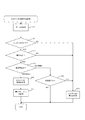
- FIGS. 4 to 8 are flowcharts for explaining operations of the engine control device 20 and the hill assist control device 30 shown in FIG. The operations of the engine control device 20 and the hill assist control device 30 will be described with reference to FIGS.
- FIG. 4 is a flowchart showing hill assist execution determination processing.
- the total weight acquisition unit 22 calculates the total weight m of the saddle riding type vehicle 10.
- the total weight acquisition unit 22 operates when the saddle riding type vehicle 10 accelerates in a substantially horizontal place.
- the friction coefficient acquisition unit 36 calculates an estimated value of the friction coefficient M. Note that the friction coefficient acquisition unit 36 according to the present embodiment operates when the saddle riding type vehicle 10 stops by braking in a substantially horizontal place.
- the hill assist control device 30 determines whether or not the state of the hill assist control device 30 is the hill assist mode (S13). The hill assist control device 30 determines that the hill assist mode is in the hill assist mode when the hill assist switch 19 is switched to the hill assist mode by an operation.
- step S13 When it is determined in step S13 that the state of the hill assist control device 30 is the hill assist mode (Yes in S13), the hill assist control device 30 determines whether or not the saddle riding type vehicle 10 is on an inclined ground. (S14). The hill assist control device 30 determines whether or not the saddle riding type vehicle 10 is on an inclined ground based on a signal output from the load sensor 11c.
- step S14 determines whether or not the straddle-type vehicle 10 is on a slope (Yes in S14). Specifically, the hill assist control device 30 determines whether or not the saddle riding type vehicle 10 is stopped based on the speed V obtained from the vehicle speed sensor 11a.
- step S15 When it is determined in step S15 that the saddle riding type vehicle 10 is stopped (Yes in S15), the saddle riding type vehicle 10 in the hill assist mode is stopped on the slope. In this case (Yes in S15), the hill assist control device 30 determines to perform hill assist (S16). Specifically, the hill assist control device 30 changes flag data (not shown) representing the hill assist state to the implementation state.
- the hill assist control device 30 sets the minimum brake pressure Pmin (S17). Specifically, the stop-time brake pressure setting unit 33 calculates a minimum brake pressure Pmin that is referred to by the brake control unit 37. The stop-time brake pressure setting unit 33 stores the calculated minimum brake pressure Pmin in a storage unit (not shown) so as to be referred to by the brake control unit 37. The stop-time brake pressure setting unit 33 according to the present embodiment calculates an estimated value of the gradient resistance based on the gradient ⁇ of the slope and the total weight m. The stop-time brake pressure setting unit 33 calculates the minimum brake pressure Pmin based on the estimated value of the gradient resistance and the friction coefficient M.
- step S15 If it is determined in step S15 that the vehicle is not stopped (No in S15), the straddle-type vehicle 10 is moving.
- the hill assist control device 30 determines whether or not the start is completed (S18). Specifically, the hill assist control device 30 determines that the start is complete when the speed of the saddle riding type vehicle 10 obtained based on the signal from the vehicle speed sensor 11a is larger than a predetermined reference value. .
- the hill assist control device 30 determines to stop the hill assist (S19). Specifically, the hill assist control device 30 changes flag data (not shown) representing the hill assist state to the non-execution state.
- step S13 If it is determined in step S13 that the vehicle is not in the hill assist mode (No in S13), the stop-time brake pressure setting unit 33 determines to stop the hill assist (S19). If it is determined in step S14 that the vehicle is not inclined (No in S14), the stop-time brake pressure setting unit 33 determines to stop the hill assist (S19). Specifically, the flag data is changed to a non-execution state. The hill assist is performed during a period from when the saddle riding type vehicle 10 stops on the slope to when the saddle riding type vehicle 10 starts.
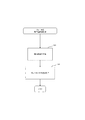
- FIG. 5 is a flowchart showing the hill assist process.
- the hill assist process is repeated.
- the hill assist control device 30 determines whether or not hill assist is being performed (S21). Specifically, the hill assist control device 30 determines whether or not the flag data representing the hill assist state is in the implementation state.
- the hill assist control device 30 performs a brake pressure command value calculation process (S22).
- the hill assist control device 30 calculates a command value Psc for the brake pressure based on the minimum brake pressure Pmin.
- the hill assist control device 30 performs an engine correction command value calculation process (S23).
- the hill assist control device 30 calculates an engine correction command value for rotating the engine 13 at a stable rotational speed.
- the engine correction command value is, for example, a torque correction value Ta.
- the hill assist control device 30 After the brake pressure command value calculation process (S22) and the engine correction command value calculation process (S23), the hill assist control device 30 performs a command value update process (S24).
- the hill assist control device 30 outputs the brake pressure command value Psc calculated in the brake pressure command value calculation process (S22) to the brake pressure adjustment device 40.
- the brake pressure adjusting device 40 controls the brake device 15 according to the command value Psc.
- the hill assist control device 30 outputs the torque correction value Ta calculated in the engine correction command value calculation process (S23) to the engine control unit 25.
- the engine control unit 25 controls the engine 13 according to the torque correction value Ta.
- step S21 If it is determined in step S21 that hill assist is not being performed (No in S21), the hill assist control device 30 performs a hill assist stop process (S25). Specifically, the brake control unit 37 sets the command value Psc of the brake pressure to 0. As a result, the brake force Fb of the brake device 15 becomes zero.
- FIG. 6 is a flowchart showing the brake pressure command value calculation process shown in FIG.
- the brake control unit 37 of the hill assist control device 30 acquires the drive state (S31). Further, the brake pressure control unit 39 obtains an estimated value of the driving force Fd from the driving force estimation unit 24. The brake control unit 37 obtains the operation amount Ob of the brake operation unit 17.
- the brake control unit 37 calculates a command value for brake pressure (S32).
- the brake control unit 37 calculates a brake pressure Psc for operating the brake device 15 based on the minimum brake pressure Pmin set by the stop-time brake pressure setting unit 33.
- the brake control unit 37 temporarily stores the calculated brake pressure Psc in a storage device (not shown).
- the subsequent command value update process (S24 in FIG. 5) when the read brake pressure Psc is output to the brake pressure adjusting device 40, the brake device 15 of the straddle-type vehicle operates with the brake pressure Psc.
- the brake control unit 37 sets a brake pressure (Pmin + Pma) obtained by adding a predetermined margin Pma to the minimum brake pressure Pmin as an initial value of the brake pressure command value Psc.
- the driver increases the accelerator operation amount Oa of the accelerator operation unit 16 when the saddle riding type vehicle 10 stopped on the slope is started. As a result, the driving force Fd increases from zero.
- the brake pressure control unit 39 The brake pressure command value Psc is controlled so that the brake pressure command value Psc output from the brake control unit 37 decreases substantially following the decrease in the brake force Fb.
- the brake control unit 37 outputs the brake pressure (Pmin + Pma) until the braking force Fb starts to decrease after the saddle riding type vehicle 10 stops.
- the brake control unit 37 outputs the brake pressure (Pmin + Pma) while the driving force Fd is 0 after the saddle riding type vehicle 10 stops. Details of control by the brake control unit 37 and the brake pressure control unit 39 will be described later.
- FIG. 7 is a flowchart showing the engine correction command value calculation process shown in FIG.
- the engine correction command value calculation process when the saddle riding type vehicle 10 starts off on an inclined ground, a target rotation speed that stabilizes the operation of the engine 13 is obtained.
- the engine torque correction unit 38 obtains the accelerator operation amount. Specifically, the engine torque correction unit 38 obtains the operation amount Oa of the accelerator operation unit 16 (S41).
- the engine torque correction unit 38 calculates a torque correction value (S43).
- the engine torque correction unit 38 calculates a torque correction value Ta such that the engine 13 rotates at a target rotation speed based on the operation amount Oa when the load on the engine 13 increases.
- the calculated torque correction value Ta is temporarily stored in a storage device (not shown).
- FIG. 8 is a flowchart showing the command value update process shown in FIG.
- the brake control unit 37 of the hill assist control device 30 reads again the command value Psc of the brake pressure calculated in step S32 from a storage device (not shown) (S51).
- the engine control unit 25 reads the torque correction value Ta obtained in step S43 from a storage device (not shown) (S52).
- the engine control unit 25 calculates the output torque target of the engine 13 by correcting the accelerator operation amount Oa of the accelerator operation unit 16 according to the torque correction value Ta.
- the brake control unit 37 outputs the read brake pressure Psc to the brake pressure adjusting device 40 (S53). Thereby, the brake control unit 37 operates the brake device 15 based on the command value Psc of the brake pressure calculated in step S32.
- the engine control unit 25 outputs an output torque target. Specifically, the engine control unit 25 controls the engine 13 so that the engine 13 outputs the output torque target torque. Thereby, the torque corrected by the torque correction value Ta is output from the engine 13. As a result, the rotational speed of the engine 13 is stabilized when starting on an inclined ground.
- step S32 the brake control unit 37 calculates a brake pressure Psc for operating the brake device 15 based on the minimum brake pressure Pmin.
- the minimum brake pressure Pmin is a brake pressure calculated to produce a brake capacity Cb substantially equal to the gradient resistance Rs.
- the brake control unit 37 outputs a brake pressure (Pmin + Pma) obtained by adding a margin Pma to the minimum brake pressure Pmin to the brake device 15 as the brake pressure command value Psc.
- the brake device 15 operates with the brake pressure (Pmin + Pma)
- the brake capacity Cb generated in the brake device 15 becomes larger than the gradient resistance Rs. That is, the upper limit of the magnitude of the braking force Fb is larger than the gradient resistance Rs.
- the saddle riding type vehicle 10 does not have a door or the like. Therefore, for example, it is easy for passengers to get on and off while the vehicle is stopped. That is, in the saddle riding type vehicle 10, the gradient resistance is likely to fluctuate while the vehicle is stopped due to the fluctuation of the total weight. Further, the calculated brake pressure Psc may contain an error. According to the present embodiment, since the brake capacity Cb has a margin with respect to the gradient resistance Rs, a situation in which the straddle-type vehicle 10 moves backward due to, for example, a variation or error in the gradient resistance can be suppressed. Therefore, the stability of the saddle riding type vehicle 10 is assisted when starting on an inclined ground or the like.
- the brake control unit 37 decreases the command value Psc of the brake pressure according to the increase rate of the driving force Fd.
- the brake pressure command value Psc of the brake device 15 decreases substantially following the decrease in the brake force Fb. Further, at the time when the reduction of the braking force starts, the reduction of the brake pressure command value Psc starts.
- the brake capacity Cb of the brake device 15 decreases.
- the brake capacity Cb is the limit of the brake force Fb. For this reason, if the brake capacity Cb further decreases after the brake capacity Cb becomes equal to the brake force Fb while the brake capacity Cb is decreasing, the brake force Fb decreases as the brake capacity Cb decreases. As a result, the balance between the driving force Fd, the braking force Fb, and the gradient resistance Rs can be solved. Accordingly, the saddle riding type vehicle 10 starts. The saddle riding type vehicle 10 starts without moving backward.
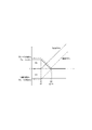
- FIG. 9A is a graph showing a change in force acting on the straddle-type vehicle 10 that starts on a sloping ground under the control of the engine control device 20 and the hill assist control device 30 of the present embodiment.
- the horizontal axis of the graph represents time.
- the vertical axis of the graph represents force.
- the force generated toward the front of the saddle riding type vehicle 10 that is, the force generated toward the upper part of the slope is displayed as a positive force.
- the graph in FIG. 9A shows a period from when the saddle riding type vehicle 10 stops on an inclined ground until the saddle riding type vehicle 10 starts. In addition, the brake operation by the driver is not performed. That is, FIG.
- FIG. 9A shows a process in which the brake force Fb of the brake device 15 becomes zero from the state where the brake device 15 is operated without performing the brake operation when the saddle riding type vehicle 10 is started. Yes.
- the graph in FIG. 9A schematically shows the force relationship while ignoring rolling resistance, air resistance, and the like in order to make the force relationship easy to understand.
- the rolling resistance and air resistance are much smaller than the gradient resistance, so there is no effect even if ignored.
- the gradient resistance Rs is a force toward the rear of the saddle riding type vehicle 10.
- the hill assist control device 30 controls the brake pressure adjusting device 40 to cause the brake device 15 to generate a brake force Fb when the saddle riding type vehicle 10 stops on an inclined ground. Specifically, when the brake device 15 is operated, a brake capacity Cb corresponding to the command value Psc of the brake pressure (see FIG. 3) is generated. The brake force Fb is generated with the brake capacity Cb as the upper limit of the magnitude. The braking force Fb while the vehicle is stopped is generated as a reaction force of a combined force of forces other than the braking force Fb that acts on the saddle riding type vehicle 10.
- the braking force Fb Prior to time t1, since the driving force Fd is 0, the braking force Fb is generated as a reaction force of the gradient resistance Rs.
- the state before time t1 corresponds to the state shown in FIG. Note that the braking force Fb is generated both in front and rear of the saddle riding type vehicle 10 with the brake capacity Cb as a limit. For this reason, the brake capacity Cb is shown in both the positive and negative regions in the graph of FIG.
- the brake pressure control unit 39 causes the brake pressure command value Psc to decrease following the decrease in the brake force Fb. For this reason, the brake capacity Cb decreases following the decrease in the brake force Fb. That is, the brake capacity Cb decreases as the driving force Fd increases. Since the brake pressure command value Psc starts decreasing when the braking force Fb starts decreasing, the braking capacity Cb starts decreasing when the braking force Fb starts decreasing.
- the braking force Fb becomes substantially zero.
- the driving force Fd further increases after time t2, the braking force Fb becomes a negative value.
- the negative braking force Fb prevents the saddle riding type vehicle 10 from moving forward by the driving force Fd.
- the decreasing brake capacity Cb becomes equal to the braking force Fb. Thereafter, when the brake capacity Cb further decreases, the brake force Fb decreases as the brake capacity Cb decreases. Further, when the driving force Fd exceeds the sum of the gradient resistance Rs and the braking force Fb at time t4, a propulsive force Fm is generated. As a result, the saddle riding type vehicle 10 starts.
- FIG. 9B is a graph showing a change in force acting in a comparative example in which the present embodiment and the brake pressure setting unit at the time of stop are different.
- the comparative example according to the graph of FIG. 9B is configured such that the brake pressure command value Psc decreases when the driving force Fd exceeds the brake capacity Cb. Therefore, even if the driving force Fd starts to increase from 0 by the start operation and the braking force Fb starts to decrease, the braking capacity Cb does not start to decrease. For this reason, after time t1 when the driving force Fd starts increasing from 0, the difference between the braking force Fb and the braking capacity Cb is large.
- the brake pressure of the brake device is reduced so that the command value Psc of the brake pressure of the brake device 15 decreases substantially following the decrease of the brake force Fb.
- the pressure command value Psc is controlled. For this reason, after time t1 when the driving force Fd starts increasing from 0, the difference between the braking force Fb and the braking capacity Cb is small. Therefore, the time from when the brake capacity Cb decreases at t1 to when the brake capacity Cb becomes equal to the magnitude of the brake force Fb at time t4 is short. Further, after the brake force Fb becomes negative, the magnitude of the brake force Fb is small when the brake capacity Cb becomes equal to the magnitude of the brake force Fb (t4).
- the portion where the negative braking force Fb is generated is hatched.
- the negative braking force Fb acts to prevent the saddle riding type vehicle 10 from starting due to the driving force Fd.
- the driver feels caught by the start of the saddle riding type vehicle.
- a saddle-ride type vehicle is lighter than, for example, an automobile.
- the driver usually puts his feet on the ground. For this reason, the driver of the saddle riding type vehicle 10 tends to feel the movement of the saddle riding type vehicle 10 sensitively.
- the driver of the saddle riding type vehicle 10 feels a sense of catch and a sudden torque change more sensitively.
- the negative braking force Fb is generated in the period from time t2 to time t5.
- the difference between the brake capacity Cb and the brake force Fb after the brake force Fb decreases at t1 is smaller than that in the comparative example.
- the period in which the negative braking force Fb occurs is the period in which the negative braking force Fb in the comparative example occurs (from t2 ′ to t5 ′ in FIG. 9B). Shorter than.
- the brake pressure Psc of the brake device 15 decreases substantially following the decrease in the brake force Fb.
- the brake capacity Cb determined according to the brake pressure Psc is larger than the gradient resistance Rs. That is, the brake capacity Cb is secured to the extent necessary for stopping the saddle riding type vehicle 10. For this reason, it is possible to suppress the saddle riding type vehicle 10 from moving later on the slope.
- FIG. 10 is a block diagram showing configurations of the engine control device 20 and the hill assist control device 30 in the second embodiment of the present invention.
- the hill assist control device 30 of the present embodiment is configured to set a brake pressure for stopping the saddle riding type vehicle 10 based on a brake pressure before stopping when the saddle riding type vehicle 10 stops by braking. This is different from the first embodiment.
- symbol in the part which is common in 1st embodiment are diverted, and difference is mainly demonstrated.
- the hill assist control device 30 shown in FIG. 10 further includes a vehicle speed acquisition unit 32A, an acceleration acquisition unit 32B, a driving force acquisition unit 34, and a brake pressure acquisition unit 35 with respect to the hill assist control device 30 shown in FIG. ing.
- the stop-time brake pressure setting unit 33 sets a brake pressure for stopping the straddle-type vehicle 10 based on the brake pressure before the stop when the straddle-type vehicle 10 stops due to braking. Set.
- the brake pressure acquisition unit 35 obtains the brake pressure Pb from the brake pressure adjustment device 40.
- the brake pressure acquisition unit 35 according to this embodiment always obtains the brake pressure Pb.
- the brake pressure acquisition unit 35 stores the obtained brake pressure Pb in a storage device (not shown).
- the brake pressure acquisition unit 35 obtains the brake pressure Pb even when the saddle riding type vehicle 10 stops due to braking.
- the brake pressure Pb before stopping when the saddle riding type vehicle 10 stops due to braking is defined as brake pressure Pbh.
- the brake pressure Pbh before stopping when the saddle riding type vehicle 10 stops by braking is used for setting the brake pressure Pmin for stopping the saddle riding type vehicle 10.
- the brake pressure acquisition unit 35 may obtain only the brake pressure Pbh before stopping.
- the vehicle speed acquisition unit 32 ⁇ / b> A obtains the speed V of the saddle riding type vehicle 10. Specifically, the vehicle speed acquisition unit 32A obtains the speed V of the saddle riding type vehicle 10 from the vehicle speed sensor 11a. The vehicle speed acquisition unit 32A according to the present embodiment always obtains the speed V of the saddle riding type vehicle 10. The vehicle speed acquisition unit 32A stores the obtained speed V in a storage device (not shown). The vehicle speed acquisition unit 32A also obtains the speed V when the brake pressure acquisition unit 35 obtains the brake pressure Pbh before stopping. A speed V at which the brake pressure Pbh before stopping is obtained is defined as a speed Vh.
- the speed Vh of the saddle riding type vehicle 10 when the brake pressure Pbh before stopping is input is used to set the brake pressure Pmin for stopping the saddle riding type vehicle 10.
- the vehicle speed acquisition unit 32A may obtain only the speed Vh of the saddle riding type vehicle 10 when the brake pressure Pbh before stopping is obtained.
- the acceleration acquisition unit 32B obtains the acceleration Ah of the straddle-type vehicle 10 based on the speed Vh of the straddle-type vehicle 10 obtained by the vehicle speed acquisition unit 32A.
- the acceleration acquisition unit 32B calculates the acceleration Ah based on the difference between the speeds Vh input at a plurality of timings.
- the driving force acquisition unit 34 obtains the driving force Fd of the saddle riding type vehicle 10 from the driving force estimation unit 24.
- the driving force acquisition unit 34 according to the present embodiment always obtains the driving force Fd of the saddle riding type vehicle 10.
- the driving force acquisition unit 34 stores the obtained driving force Fd in a storage device (not shown).
- the driving force acquisition unit 34 obtains the driving force Fd even before stopping when the saddle riding type vehicle 10 stops due to braking.
- the driving force Fd before stopping when the saddle riding type vehicle 10 stops by braking is defined as driving force Fdh.
- the driving force Fd before stopping when the saddle riding type vehicle 10 stops by braking is used for setting a brake pressure Pmin for stopping the saddle riding type vehicle 10.
- the driving force acquisition unit 34 may obtain only the driving force Fdh before stopping.
- the stop-time brake pressure setting unit 33 sets a brake pressure for stopping the straddle-type vehicle 10 based on the brake pressure Pbh input by the brake pressure acquisition unit 35. More specifically, the stop-time brake pressure setting unit 33 according to the present embodiment is the minimum brake pressure required to stop the saddle riding type vehicle 10 on the slope as a brake pressure for stopping the saddle riding type vehicle 10. Calculate The minimum brake pressure required to stop the saddle riding type vehicle 10 on the slope is referred to as a minimum brake pressure Pmin.
- the minimum brake pressure Pmin is a brake pressure that generates a brake capacity Cb substantially equal to the gradient resistance Rs acting on the saddle riding type vehicle 10.
- the stop-time brake pressure setting unit 33 according to the present embodiment sets the minimum brake pressure Pmin based on the brake pressure Pbh before stopping input by the brake pressure acquisition unit 35.
- the stop-time brake pressure setting unit 33 includes the acceleration (deceleration) Ah obtained by the vehicle speed obtaining unit 32A and the total weight m obtained by the total weight obtaining unit 22 in addition to the brake pressure Pbh. Based on the estimated value, the minimum brake pressure Pmin is calculated. More specifically, the stop-time brake pressure setting unit 33 calculates the gradient resistance Rs based on the brake pressure Pbh obtained by the brake pressure obtaining unit 35 and the estimated value of the driving force Fd obtained by the driving force obtaining unit 34. To do. The brake pressure setting unit 33 at the time of stopping calculates, for example, a gradient resistance Rs acting on the vehicle using the equation of motion shown below.
- the stop-time brake pressure setting unit 33 calculates the minimum brake pressure Pmin based on the brake pressure Pbh before stopping when the straddle-type vehicle 10 stops due to braking.
- the stop-time brake pressure setting unit 33 constantly calculates the minimum brake pressure Pmin.
- the stop-time brake pressure setting unit 33 outputs the minimum brake pressure Pmin calculated before the stop so as to be referred to by the brake control unit 37 only when the saddle riding type vehicle 10 stops on the slope.
- the stop-time brake pressure setting unit 33 stores the minimum brake pressure Pmin in a storage unit (not shown) so as to be referred to by the brake control unit 37. Thereby, the minimum brake pressure Pmin is set.
- the stop-time brake pressure setting unit 33 sets the minimum brake pressure Pmin based on the brake pressure Pbh before stopping. For this reason, the friction coefficient of the brake device 15 of the straddle-type vehicle 10 before stopping is reflected in the minimum brake pressure Pmin. For example, when the temperature of the brake pad 15a is high, the friction coefficient is small. When the straddle-type vehicle 10 stops due to braking, if the friction coefficient is small, a large brake pressure Pbh is applied to obtain a desired acceleration (deceleration). As a result, the minimum brake pressure Pmin obtained using the above equation of motion increases.
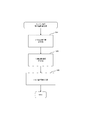
- FIG. 11 is a flowchart showing hill assist execution determination processing of the engine control device 20 and the hill assist control device 30 of the second embodiment.
- the brake pressure acquisition unit 35, the vehicle speed acquisition unit 32A, and the acceleration acquisition The unit 32B and the driving force acquisition unit 34 operate. Based on the results of these operations, the minimum brake pressure Pmin is acquired (S12) after the data acquisition process (S11).
- the brake pressure acquisition unit 35 obtains the brake pressure Pb from the brake pressure adjustment device 40. Further, the vehicle speed acquisition unit 32A obtains the speed V of the saddle type vehicle. The acceleration acquisition unit 32B obtains the acceleration Ah of the saddle riding type vehicle 10. Further, the driving force acquisition unit 34 obtains the driving force Fd from the driving force estimation unit 24.
- the stop-time brake pressure setting unit 33 calculates the minimum brake pressure Pmin for stopping the saddle riding type vehicle 10 on the slope.
- the stop-time brake pressure setting unit 33 of the present embodiment calculates the minimum brake pressure Pmin by calculating the estimated value of the gradient resistance Rs. Specifically, the stop-time brake pressure setting unit 33 calculates the gradient resistance Rs based on the acceleration Ah, the total weight m, the brake force Fb, and the driving force Fd. In the present embodiment, the brake pressure obtained from each data before stopping when the saddle riding type vehicle 10 stops by braking is set as the effective minimum brake pressure Pmin. That is, the driving force acquisition unit 34 sets the minimum brake pressure Pmin for stopping the saddle riding type vehicle 10 based on the brake pressure Pbh before stopping as a result of the process of step S17.
- the stop-time brake pressure setting unit 33 sets the minimum brake pressure Pmin only when, for example, the state of the hill assist control device 30 is the hill assist mode and the straddle-type vehicle 10 is on a slope (Yes in S14). You may calculate.
- step S17 the stop-time brake pressure setting unit 33 sets a minimum brake pressure Pmin referred to by the brake control unit 37.
- step S12 the stop-time brake pressure setting unit 33 repeatedly calculates the minimum brake pressure Pmin regardless of the state of the saddle riding type vehicle 10, and stores it in a storage device (not shown). At the time when the process of step S17 is performed, the minimum brake pressure Pmin obtained based on the brake pressure Pbh before stopping on the slope is stored as the latest minimum brake pressure Pmin. When it is determined that the straddle-type vehicle 10 has stopped on the slope (Yes in S15), the stop-time brake pressure setting unit 33 uses the latest minimum brake pressure Pmin as the minimum brake pressure Pmin referred to by the brake control unit 37. Set as.
- the brake pressure setting unit 33 at the time of stoppage is set to the minimum brake pressure that is referred to the brake control unit 37, based on the brake pressure Pbh, the speed Vh, the acceleration Ah, and the driving force Fdh before the stop on the slope. Set as brake pressure Pmin.
- step S12 the hill assist control device 30 sets not the latest minimum brake pressure Pmin but the minimum brake pressure Pmin obtained several times before as the minimum brake pressure Pmin referred to by the brake control unit 37. May be. That is, the hill assist control device 30 sets the minimum brake pressure Pmin obtained a predetermined time before the time when the vehicle speed becomes 0 as the minimum brake pressure for stopping the saddle riding type vehicle 10. May be.
- the brake control unit 37 acquires the brake pressure command value in step S32 shown in FIG. 6 as in the first embodiment.
- the brake control unit 37 obtains a brake pressure command value Psc based on the minimum brake pressure Pmin set by the stop-time brake pressure setting unit 33.
- the brake control unit 37 sets a brake pressure (Pmin + Pma) obtained by adding a predetermined margin Pma to the minimum brake pressure Pmin as an initial value of the brake pressure command value Psc.
- the margin Pma is, for example, 10% to 40% of the minimum brake pressure Pmin. However, the margin Pma may be outside the range of 10% to 40%.
- the brake pressure (Pmin + Pma) is output to the brake pressure adjusting device 40 as the command value Psc.
- the minimum brake pressure Pmin is calculated by directly using the estimated value of the friction coefficient obtained by the friction coefficient acquisition unit 36.
- the friction coefficient acquisition unit 36 calculates the friction coefficient only when the saddle riding type vehicle 10 is braked at a substantially horizontal place. For example, in the case where the saddle riding type vehicle 10 continues traveling on a sloping ground and then stops on a sloping ground, the friction coefficient obtained by the friction coefficient acquisition unit 36 reflects the state of the brake device 15 when the vehicle stops on a sloping ground. It has not been. In this case, the friction coefficient obtained by the friction coefficient acquisition unit 36 may be significantly different from that of the brake device 15 when the vehicle stops on the slope.
- the minimum brake pressure Pmin set based on the brake pressure Pbh before stopping reflects the friction coefficient at that time. Therefore, the minimum brake pressure Pmin of the brake device 15 that operates when the brake is not operated is appropriately set. For this reason, the margin Pma included in the minimum brake pressure Pmin + Pma of the brake device 15 that operates when the brake is not operated can be suppressed. Therefore, the brake pressure (Pmin + Pma) of the brake device 15 that is activated when the brake is not operated is suppressed from becoming excessively large compared to the brake pressure Pmin that is necessary for maintaining the saddle riding type vehicle 10 to stop.
- the saddle riding type vehicle 10 starts by the driver's accelerator operation, the time required to release the brake pressure is shortened. Therefore, it is suppressed that the driver feels a catch or a sudden torque change.
- the brake pressure of the brake device 15 that operates when the brake is not operated is set appropriately, the saddle riding type vehicle 10 is restrained from moving backward on the slope. Therefore, the stability of the saddle riding type vehicle 10 at the time of start is enhanced.
- FIG. 12 is a graph showing a change in force acting on the straddle-type vehicle 10 starting on a sloping ground under the control of the engine control device 20 and the hill assist control device 30 of the second embodiment.
- the brake capacity Cb in FIG. 12 is generated according to the brake pressure Psc.
- the brake pressure Psc output from the brake control unit 37 of the hill assist control device 30 is the sum Pmin + Pma of the minimum brake pressure Pmin and the margin Pma.
- the minimum brake pressure Pmin is a brake pressure set by the stop-time brake pressure setting unit 33 so as to generate a brake capacity Cb substantially equal to the gradient resistance Rs.
- the minimum brake pressure Pmin is set based on the brake pressure Pbh before stopping.
- the brake pressure Pbh before stopping reflects the friction coefficient of the brake device of the saddle type vehicle at that time. For this reason, the margin Pma applied to the minimum brake pressure Pmin can be suppressed.
- the brake pressure (Pmin + Pma) of the brake device that operates when the brake is not operated is suppressed from becoming excessively large compared to the brake pressure Pmin that is necessary to maintain the saddle riding type vehicle. That is, the brake capacity Cb is suppressed from becoming excessively large compared to the gradient resistance Rs.
- the state of the brake device when the vehicle is stopped is reflected in the brake pressure that activates the brake device when the brake is not operated.
- the difference between the brake capacity Cb and the gradient resistance Rs is small compared to the case of the first embodiment shown in FIG.
- the time until the utterance of the brake capacity Cb stops is short. Therefore, the period during which the negative braking force Fb is generated (from t2 to t5) is shorter than that in the first embodiment shown in FIG. For this reason, according to this embodiment, it is possible to perform a smooth start while further suppressing the driver from feeling caught.
- the brake pressure control unit 39 reduces the brake pressure of the brake device 15 when the brake force decreases, and brakes when the brake force increases.
- the brake pressure of the device 15 is increased.
- the brake pressure control unit 39 reduces the command value Psc of the brake pressure of the brake device 15 substantially following the increase of the driving force Fd and decreases the command value Psc of the brake pressure.
- the brake pressure command value Psc is adjusted so as to increase substantially following the decrease in the driving force Fd. More specifically, the brake pressure control unit 39 reduces the command value Psc of the brake pressure by an amount corresponding to the increase amount of the driving force Fd, and the command value of the brake pressure by an amount corresponding to the decrease amount of the drive force Fd. Increase Psc.
- FIG. 13 is a graph showing a change in force acting on the straddle-type vehicle 10 starting on an inclined ground under the control of the engine control device 20 and the hill assist control device 30 of the third embodiment.
- the brake capacity Cb decreases when the brake force Fb decreases, while the brake capacity Cb increases when the brake force Fb increases.
- the driver may return the operation while operating the accelerator operation unit 16 in order to start the saddle riding type vehicle 10.
- the operation amount decreases
- the braking force Fb decreases, and the situation where the saddle riding type vehicle 10 moves later is suppressed. Therefore, the stability of the saddle riding type vehicle 10 is further strongly assisted while further suppressing the driver from feeling caught.
- the brake pressure control unit 39 that reduces the brake pressure of the brake device at a rate corresponding to the reduction rate of the brake force has been described.
- the brake control unit may decrease the command value Psc of the brake pressure by the amount of decrease in the brake force.
- the brake pressure control unit 39 that starts the decrease in the brake pressure command value Psc when the decrease in the brake force starts is described.
- the brake pressure control unit may start a decrease in the brake pressure of the brake device after a predetermined delay time has elapsed after the decrease in the brake force has started.
- the gradient resistance Rs is calculated, and the brake pressure setting unit at the time of stop is calculated from the gradient resistance Rs. 33 has been described.
- the present invention is not limited to this.
- the stop-time brake pressure setting unit may directly calculate the brake pressure for stopping the saddle riding type vehicle without calculating the gradient resistance.
- the stop-time brake pressure setting unit may acquire a brake pressure for stopping the saddle riding type vehicle by reading a value from a table previously associated with data.
- the stop-time brake pressure setting unit 33 that directly uses the total weight m, the acceleration Ah, the driving force Fdh, and Fbh to obtain the minimum brake pressure Pmin has been described.
- the stop-time brake pressure setting unit may acquire the brake pressure for stopping the saddle riding type vehicle without directly using the total weight obtained by the detection.
- the stop-time brake pressure setting unit may acquire the brake pressure for stopping the saddle riding type vehicle with the total weight as a fixed value.
- the stop-time brake pressure setting unit may acquire the brake pressure without directly using the driving force Fdh before the stop.
- the stop-time brake pressure setting unit may acquire a brake pressure for stopping the saddle riding type vehicle with the driving force before the stop being a fixed value. Further, the stop-time brake pressure setting unit may acquire the brake pressure without directly using the acceleration before the stop. For example, the stop-time brake pressure setting unit may acquire the brake pressure by directly using the speed instead of the acceleration. Further, the stop-time brake pressure setting unit may acquire the brake pressure without using the acceleration and speed before the stop.
- the brake control unit 37 that operates the brake device when the driver does not perform a brake operation has been described.
- the brake control unit may actuate the brake device, for example, by detecting the release or decrease of the brake operation by the driver. Further, the brake control unit may operate the brake device by detecting a brake operation by the driver, for example.
- the engine control apparatus 20 and the hill assist control apparatus 30 demonstrated having each provided the central processing unit and the memory
- the control device may be configured by, for example, wired logic.
- calculation of each value has been described.
- the “calculation” is not limited to calculating a mathematical expression by directly using an input value. The calculation includes, for example, reading a value corresponding to an input value using a table or map composed of a plurality of numbers associated with each other.
- the brake device 15 constituting the disc brake has been described.
- the brake device may be a drum brake, for example.
- the brake pressure acquisition unit 35 that obtains the brake pressure based on the hydraulic pressure of the hydraulic fluid has been described.
- the brake pressure acquisition unit may obtain the brake pressure based on the operation amount of the brake operation unit, for example.
- the minimum brake pressure Pmin that generates the brake capacity Cb substantially equal to the gradient resistance Rs has been described as the brake pressure for stopping the saddle riding type vehicle 10.
- the brake pressure for stopping the saddle riding type vehicle may be a brake pressure that generates a brake capacity larger than the gradient resistance.
- the brake pressure acquisition unit 35 that obtains a brake pressure before stopping when the straddle-type vehicle 10 stops on a sloping ground, and the brake that operates the brake device 15 when the straddle-type vehicle 10 is on a sloping ground.
- the control unit 37 has been described.
- the brake pressure acquisition unit may obtain the brake pressure before stopping when the saddle riding type vehicle stops at a substantially horizontal place.
- the brake control unit may operate the brake device when the saddle riding type vehicle is in a substantially horizontal place. For example, when loading and unloading luggage, the saddle riding type vehicle is stabilized.
- the present invention is not limited to the above-described example, and for example, the following configurations (6) to (9) can be adopted. Examples of the following (6) to (9) include the above-described embodiments.
- the straddle-type vehicle control device is configured to operate a brake device of the saddle riding type vehicle when a braking operation by a driver is not performed while the saddle riding type vehicle is stopped on an inclined ground.
- the brake pressure of the brake device is reduced in a process in which the brake force of the brake device becomes zero from the state where the brake device is operated without performing the brake operation.
- a brake pressure control unit configured to control the brake pressure of the brake device so as to substantially decrease following the decrease in the brake force.
- the straddle-type vehicle control device acts on the straddle-type vehicle with a braking force having an upper limit of a brake capacity corresponding to a brake pressure at which the brake device operates in a stopped state of the straddle-type vehicle.
- the brake pressure control unit reduces the brake force of the brake device in a process in which the brake force of the brake device becomes zero from a state in which the brake device is operated without performing the brake operation.
- the brake pressure of the brake device is controlled so as to substantially follow and decrease.
- the brake control unit In the process in which the brake force of the brake device becomes zero from the state in which the brake device is operated without the brake operation being performed, the brake control unit is configured to reduce the brake capacity before the brake force starts to decrease.
- the brake device is configured to operate at a brake pressure that is greater than or substantially equal to the gradient resistance acting on the saddle riding type vehicle due to the gradient of the slope.
- the straddle-type vehicle control device acts on the straddle-type vehicle with a braking force having an upper limit of a brake capacity corresponding to a brake pressure at which the brake device operates in a stopped state of the straddle-type vehicle.
- the brake pressure setting unit at the time of stop is a brake for stopping the straddle-type vehicle so that the brake capacity is greater than or substantially equal to a gradient resistance acting on the straddle-type vehicle due to a slope of a slope. Set the pressure.
Abstract
本発明は、傾斜地等での発進時に鞍乗型車両の安定性を補助し、運転者が引っ掛かり感を覚えることを抑制しつつ、スムースな発進を行うことを可能とする鞍乗型車両用制御装置を提供することを課題とする。本発明は、鞍乗型車両用制御装置であって、前記制御装置は、前記鞍乗型車両の停車中に運転者によるブレーキ操作が解除されて前記ブレーキ操作が行われていない時に、前記鞍乗型車両のブレーキ装置を作動させるように構成されたブレーキ制御部と、前記鞍乗型車両の発進時に、前記ブレーキ操作が行われずに前記ブレーキ装置が作動している状態から前記ブレーキ装置のブレーキ力がゼロになる過程において、前記ブレーキ装置のブレーキ圧が前記ブレーキ力の減少に追随して減少するように、前記ブレーキ装置のブレーキ圧を制御するように構成されたブレーキ圧制御部とを備える。
Description
本発明は、鞍乗型車両用制御装置及び鞍乗型車両に関する。
通常、坂道での発進では、運転者がブレーキとアクセルとを同時に又は連続的に操作する。坂道での発進は、一般的に、比較的高い運転技能を必要とする。そのため、坂道での発進が難しいと考える運転者は少なくない。そこで、坂道での発進を補助するためのシステムとして、従来、ブレーキ操作が必要ない坂道発進支援ブレーキ装置がある。
特許文献1は、従来の鞍乗型車両用制御装置の一例として、自動二輪車用坂道発進支援ブレーキ装置を開示している。前記自動二輪車用坂道発進支援ブレーキ装置は、車両停止時に、車両の停止を検出し、運転者によるブレーキ入力の解除を検出する。前記ブレーキ装置は、次に、運転者によるブレーキ入力の解除時の車両の総ブレーキ力を算出する。前記ブレーキ装置は、更に、車両の停止を維持するために必要なブレーキ力を計算する。そして、前記ブレーキ装置は、算出された総ブレーキ力で車両の停止を維持できるか否かを判断する。前記ブレーキ装置は、車両の停止を維持できないと判断した時には、車両の総ブレーキ力を増加させる。特許文献1に開示のブレーキ装置によれば、坂道発進支援制御機能により、運転者の操作を介さずに坂道等で停車状態に応じたブレーキ圧を維持するのに必要なブレーキ力を保持することができる。
また、特許文献1に開示のブレーキ装置は、エンジンの回転数や車輪速度等から運転者の発進意思の有無を判断し、運転者の発進意思があると判断した場合、ブレーキ圧を解除する。このように、特許文献1に開示のブレーキ装置では、エンジンの回転数や車輪速度等に基づいて、坂道発進支援制御機能が解除され、車両の発進が可能になる。
しかしながら、特許文献1に開示されるようなブレーキ装置によれば、運転者が期待する車両発進のタイミングで、円滑に鞍乗型車両を発進させることができないことがあった。このように、鞍乗型車両の発進が運転者の発進意思に適切に追従しない場合、運転者が鞍乗型車両の発進に対して、引っ掛かり感を覚えることがあった。
本発明は、傾斜地等での発進時に鞍乗型車両の安定性を補助し、運転者が引っ掛かり感を覚えることを抑制しつつ、スムースな発進を行うことを可能とする鞍乗型車両用制御装置、及び鞍乗型車両を提供することである。
本発明は、上述した課題を解決するために、以下の構成を採用する。
(1) 鞍乗型車両用制御装置であって、
前記制御装置は、
前記鞍乗型車両の停車中に運転者によるブレーキ操作が行われていない時に、前記鞍乗型車両のブレーキ装置を作動させるように構成されたブレーキ制御部と、
前記鞍乗型車両の発進時に、前記ブレーキ操作が行われずに前記ブレーキ装置が作動している状態から前記ブレーキ装置のブレーキ力がゼロになる過程において、前記ブレーキ装置のブレーキ圧が前記ブレーキ力の減少に実質的に追随して減少するように、前記ブレーキ装置のブレーキ圧を制御するように構成されたブレーキ圧制御部と
を備える。
前記制御装置は、
前記鞍乗型車両の停車中に運転者によるブレーキ操作が行われていない時に、前記鞍乗型車両のブレーキ装置を作動させるように構成されたブレーキ制御部と、
前記鞍乗型車両の発進時に、前記ブレーキ操作が行われずに前記ブレーキ装置が作動している状態から前記ブレーキ装置のブレーキ力がゼロになる過程において、前記ブレーキ装置のブレーキ圧が前記ブレーキ力の減少に実質的に追随して減少するように、前記ブレーキ装置のブレーキ圧を制御するように構成されたブレーキ圧制御部と
を備える。
(1)の鞍乗型車両用制御装置によれば、運転者によるブレーキ操作が行われていない時(以下「ブレーキ非操作時」ともいう)に、ブレーキ装置が作動する。その後、鞍乗型車両の発進時に、ブレーキ操作が行われずにブレーキ装置が作動している状態からブレーキ力がゼロになる過程において、ブレーキ装置のブレーキ圧がブレーキ力の減少に実質的に追随して減少する。従って、本発明では、ブレーキ操作が行われずにブレーキ装置が作動している状態からブレーキ力がゼロになる過程において、ブレーキ圧に応じて定まるブレーキ容量を車両の停止に必要な程度確保しつつ、ブレーキ容量とブレーキ力との差が大きくなることを抑制できる。そのため、鞍乗型車両の発進を運転者の発進意思に追従させ易く、運転者が引っ掛かり感や急激なトルク変化を感じることを抑制できる。また、例えば坂道で鞍乗型車両が後退することを抑制でき、鞍乗型車両の発進時の安定性を高めることができる。このように、本願発明の鞍乗型車両用制御装置によれば、傾斜地等での発進時に鞍乗型車両の安定性を補助することができるとともに、運転者が引っ掛かり感を覚えることを抑制しつつ、スムースな発進を行うことが可能となる。
(2) (1)の鞍乗型車両用制御装置であって、
前記ブレーキ圧制御部は、前記鞍乗型車両の発進時に、前記ブレーキ操作が行われずに前記ブレーキ装置が作動している状態から前記ブレーキ装置のブレーキ力がゼロになる過程において、前記ブレーキ力が減少する時に前記ブレーキ装置のブレーキ圧が減少する一方、前記ブレーキ力が増加する時に前記ブレーキ装置のブレーキ圧が増加するように、前記ブレーキ装置のブレーキ圧を制御するように構成されている。
前記ブレーキ圧制御部は、前記鞍乗型車両の発進時に、前記ブレーキ操作が行われずに前記ブレーキ装置が作動している状態から前記ブレーキ装置のブレーキ力がゼロになる過程において、前記ブレーキ力が減少する時に前記ブレーキ装置のブレーキ圧が減少する一方、前記ブレーキ力が増加する時に前記ブレーキ装置のブレーキ圧が増加するように、前記ブレーキ装置のブレーキ圧を制御するように構成されている。
(2)の構成によれば、ブレーキ力がゼロになる過程においてブレーキ力が増加する時にブレーキ装置のブレーキ圧が増加するので、ブレーキ容量が増加する。このため、ブレーキ力が増加する時に、増加が制限されることを抑制できる。従って、ブレーキ力が増加する状況で、ブレーキ力が不足する事態が抑えられる。よって、鞍乗型車両の発進時の安定性をさらに高めることができる。
(3) (1)又は(2)の鞍乗型車両用制御装置であって、
前記ブレーキ圧制御部は、前記鞍乗型車両の発進時に、前記ブレーキ操作が行われずに前記ブレーキ装置が作動している状態から前記ブレーキ装置のブレーキ力がゼロになる過程において、前記ブレーキ力の減少が開始する時点で前記ブレーキ圧の減少が開始するように、前記ブレーキ装置のブレーキ圧を制御するように構成されている。
前記ブレーキ圧制御部は、前記鞍乗型車両の発進時に、前記ブレーキ操作が行われずに前記ブレーキ装置が作動している状態から前記ブレーキ装置のブレーキ力がゼロになる過程において、前記ブレーキ力の減少が開始する時点で前記ブレーキ圧の減少が開始するように、前記ブレーキ装置のブレーキ圧を制御するように構成されている。
(3)の構成によれば、ブレーキ力の減少が開始する時点でブレーキ圧の減少が開始するので、車両の停止に必要なブレーキ容量を確保しつつ、ブレーキ容量とブレーキ力との差を小さくすることができる。従って、運転者が引っ掛かり感を覚えることをさらに抑制しつつ、スムースな発進を行うことが可能となる。
(4) (1)~(3)のいずれか1の鞍乗型車両用制御装置であって、
前記制御装置は、更に、
前記鞍乗型車両が制動により停車する場合における停車前のブレーキ圧を得るように構成されたブレーキ圧取得部と、
少なくとも前記ブレーキ圧取得部により得られた前記停車前のブレーキ圧に基づいて、前記鞍乗型車両を停車させるためのブレーキ圧を設定するように構成された停車時ブレーキ圧設定部と
を備え、
前記ブレーキ制御部は、運転者によるブレーキ操作が行われていない時に、前記停車時ブレーキ圧設定部により設定された前記ブレーキ圧に基づいて、前記鞍乗型車両のブレーキ装置を作動させるように構成されている。
前記制御装置は、更に、
前記鞍乗型車両が制動により停車する場合における停車前のブレーキ圧を得るように構成されたブレーキ圧取得部と、
少なくとも前記ブレーキ圧取得部により得られた前記停車前のブレーキ圧に基づいて、前記鞍乗型車両を停車させるためのブレーキ圧を設定するように構成された停車時ブレーキ圧設定部と
を備え、
前記ブレーキ制御部は、運転者によるブレーキ操作が行われていない時に、前記停車時ブレーキ圧設定部により設定された前記ブレーキ圧に基づいて、前記鞍乗型車両のブレーキ装置を作動させるように構成されている。
(4)の構成によれば、運転者によるブレーキ操作が行われていない時に作動するブレーキ装置のブレーキ圧が、鞍乗型車両が制動により停車する場合における停車前のブレーキ圧に基づいて設定される。停車前のブレーキ圧には、その時点での鞍乗型車両のブレーキ装置の状態(例えば、摩擦係数μ)が反映されている。従って、(4)の構成によれば、ブレーキ非操作時に作動するブレーキ装置のブレーキ圧を適切に設定できる。これにより、ブレーキ非操作時に作動するブレーキ装置のブレーキ圧が、鞍乗型車両の停止を維持するために必要なブレーキ圧と比べて過剰に大きくなることが抑制され得る。従って、運転者が引っ掛かり感を覚えることがさらに抑制できる。
(5) 鞍乗型車両であって、
前記鞍乗型車両は、
前記鞍乗型車両の車輪と、
(1)~(4)のいずれか1の制御装置と、
前記制御装置のブレーキ制御部により作動されるブレーキ装置と
を備える。
前記鞍乗型車両は、
前記鞍乗型車両の車輪と、
(1)~(4)のいずれか1の制御装置と、
前記制御装置のブレーキ制御部により作動されるブレーキ装置と
を備える。
(5)の鞍乗型車両は、傾斜地等での発進時に鞍乗型車両の安定性を補助することができるとともに、運転者が引っ掛かり感を覚えることを抑制しつつ、スムースな発進を行うことが可能となる。
本発明の鞍乗型車両用制御装置及び鞍乗型車両によれば、傾斜地等での発進時に鞍乗型車両の安定性を補助し、運転者が引っ掛かり感を覚えることを抑制しつつ、スムースな発進を行うことが可能となる。
本願発明者らは、上述した課題について検討を行い、以下の知見を得た。
鞍乗型車両は、一般的な自動車と比べて、高い機動力を有している。鞍乗型車両では、頻繁な加減速が行われ易い。そのため、鞍乗型車両では、一般的に、ブレーキ装置が使用される頻度が高く、ブレーキ装置が備えるブレーキ部材(例えば、ディスクロータ、ブレーキパッド等)が摩擦によって加熱され易い。また、鞍乗型車両の中には、ブレーキ部材が露出するように設けられる鞍乗型車両が存在している。このような鞍乗型車両では、ブレーキ部材は、冷却され易いが、雨水や泥水等に晒され易い。このような温度及び表面状態の影響によって、ブレーキ部材の摩擦係数は変化し易い。摩擦係数の変化に伴って、ブレーキ容量は変化する。即ち、鞍乗型車両の走行時の状態や環境によって、ブレーキ容量は変化する。
特許文献1に開示のような従来のブレーキ装置では、エンジンの回転数や車輪速度等に基づいて、運転者の発進意思があると判断した場合にブレーキ圧を解除する。ところが、運転者の発進のための操作タイミングや操作量は、運転者によって異なる。また、上述したように、鞍乗型車両の走行時の状態や環境によってブレーキ容量は異なる。そのため、鞍乗型車両の発進を運転者の発進意思に追従させ難い。その結果、運転者が引っ掛かり感や急激なトルク変化を感じる場合があった。
本願発明者らは、更に検討を行った。その結果、本願発明者らは、鞍乗型車両の発進時に、ブレーキ操作が行われずにブレーキ装置が作動している状態からブレーキ装置のブレーキ力がゼロになる過程において、ブレーキ装置のブレーキ圧がブレーキ力の減少に実質的に追随して減少するように、ブレーキ装置のブレーキ圧を制御することに想到した。これにより、車両の停止に必要なブレーキ容量を確保しつつ、ブレーキ容量とブレーキ力との差が大きくなることを抑制できる。その結果、鞍乗型車両の発進を運転者の発進意思に追従させ易く、運転者が引っ掛かり感や急激なトルク変化を感じることを抑制できる。
本願発明は、上述した知見に基づいて完成された発明である。
以下、本発明の実施形態について、図面を参照しながら説明する。
以下、本発明の実施形態について、図面を参照しながら説明する。
図1は、本発明の第一実施形態における鞍乗型車両用制御装置が搭載された自動二輪車を示す側面図である。
図1に示す鞍乗型車両10は、自動二輪車である。鞍乗型車両10は、車体11及び2つの車輪12を備えている。車輪12は、車体11に回転可能に支持されている。車体11は、エンジン13、伝達機構14、及びブレーキ装置15を備えている。伝達機構14は、クラッチ14a、変速装置14b、チェーン14cを有する。エンジン13から出力された駆動力は、クラッチ14aを含む伝達機構14を介して後の車輪12に伝達される。
ブレーキ装置15は、摩擦力によって車輪12にブレーキ力を生じさせる摩擦ブレーキである。ブレーキ装置15は、ディスクブレーキで構成されている。ブレーキ装置15は、作動液の液圧で動作するブレーキパッド15aを有している。ブレーキ装置15は、ブレーキパッド15aを、車輪12と共に回転するディスクロータ12aに押し付ける。ブレーキ装置15は、ブレーキパッド15aとディスクロータ12aとの摩擦によってブレーキ力を生じさせる。ブレーキ装置15は、車輪12にブレーキ力を生じさせることによって、鞍乗型車両10を制動する。鞍乗型車両10は、制動によって減速又は停車する。また、鞍乗型車両10が例えば傾斜地にあるとき、ブレーキ力は、傾斜地で鞍乗型車両10にかかる力に対抗する。これによって、鞍乗型車両10が停車状態を維持できる。
エンジン13には、エンジン13の回転速度を検出するエンジン回転センサ13aが設けられている。エンジン回転センサ13aは、エンジン13の回転速度に応じた信号を出力する。
鞍乗型車両10は、車速センサ11a、荷重センサ11c、アクセル操作部16、ブレーキ操作部17、クラッチ操作部18、エンジン制御装置20、ヒルアシスト制御装置30、及びブレーキ圧調整装置40を備えている。
車速センサ11aは、車輪12の回転速度を検出することによって、鞍乗型車両10の速度を検出する。車速センサ11aは、鞍乗型車両10の速度に応じた信号を出力する。
荷重センサ11cは、鞍乗型車両10に掛かる荷重を検出する。荷重センサ11cは、例えば3軸加速度センサ及び3軸ジャイロセンサを有する6軸センサを含んでいる。
アクセル操作部16、ブレーキ操作部17、及びクラッチ操作部18は、運転者によって操作される。エンジン制御装置20は、アクセル操作部16の操作に基づいて、エンジン13の出力を制御する。エンジン制御装置20は、例えばエンジン13の点火タイミング、吸入空気量、及び吸入燃料を変化させることによって、エンジン13の出力を制御する。クラッチ操作部18はクラッチ14aの動作を制御する。
アクセル操作部16、ブレーキ操作部17、及びクラッチ操作部18のそれぞれには、操作を検知する図示しないセンサが設けられている。アクセル操作部16、ブレーキ操作部17、及びクラッチ操作部18は、それぞれに設けられたセンサを介して、操作量を表す信号をヒルアシスト制御装置30に出力する。
ブレーキ圧調整装置40は、ブレーキ操作部17の操作及びヒルアシスト制御装置30からの指令値に基づいて、ブレーキ装置15に生じさせるブレーキ力を調整する。
ブレーキ圧調整装置40は、運転者の操作に応じてブレーキ操作部17から出力される液圧をブレーキ装置15に供給する。ブレーキ装置15は、ブレーキ圧調整装置40から出力されるブレーキ圧で作動する。ブレーキ圧は、ブレーキパッド15aがディスクロータ12aに押し付けられる圧力である。ブレーキ装置15のブレーキパッド15aは、ブレーキ圧調整装置40から出力される液圧に応じたブレーキ圧で車輪12のディスクロータ12aに押し付けられる。ブレーキ圧調整装置40は、図示しない液圧ポンプ及びバルブを有する。例えば、ブレーキ圧調整装置40は、液圧ポンプの動作によって、ブレーキ操作部17から出力される液圧よりも高い液圧をブレーキ装置15に供給することができる。また、ブレーキ圧調整装置40は、ブレーキ非操作時にブレーキ装置15を作動させることができる。本実施形態のブレーキ装置15に設けられたブレーキ圧調整装置40は、ヒルアシスト制御装置30からのブレーキ圧の指令値に応じたブレーキ圧で、ブレーキ装置15を作動させる。
ブレーキ圧調整装置40は、ブレーキ圧を検出する図示しないセンサを備えている。詳細には、ブレーキ圧調整装置40の液圧センサは、液圧に応じた信号を出力する。作動液の液圧は、ブレーキパッド15aに生じるブレーキ圧と対応しているので、ブレーキ圧調整装置40からの信号に基づいてブレーキ圧が得られる。
ヒルアシスト制御装置30は、ブレーキ圧調整装置40を制御する。ヒルアシスト制御装置30は、ブレーキ操作部17及びアクセル操作部16の操作に基づいて、ブレーキ圧調整装置40を制御する。ヒルアシスト制御装置30は、傾斜地での鞍乗型車両10の発進操作を補助するように、ブレーキ圧調整装置40及びブレーキ装置15を制御する。傾斜地での鞍乗型車両10の発進操作を補助するブレーキ装置15を制御する機能を、ヒルアシストと称する。
鞍乗型車両10には、ヒルアシストスイッチ19が設けられている。ヒルアシストスイッチ19は、運転者に操作されることによって、ヒルアシストが動作可能なヒルアシストモードか否かを切替える。
なお、本実施形態のヒルアシスト制御装置30は、ヒルアシストに加えて、アンチロック・ブレーキング・システム(ABS)の制御機能を有することも可能である。
鞍乗型車両10には、ヒルアシストスイッチ19が設けられている。ヒルアシストスイッチ19は、運転者に操作されることによって、ヒルアシストが動作可能なヒルアシストモードか否かを切替える。
なお、本実施形態のヒルアシスト制御装置30は、ヒルアシストに加えて、アンチロック・ブレーキング・システム(ABS)の制御機能を有することも可能である。
エンジン制御装置20、ヒルアシスト制御装置30及びブレーキ圧調整装置40によって鞍乗型車両用制御装置が構成されている。エンジン制御装置20及びヒルアシスト制御装置30は、図示しない中央演算装置及び記憶装置をそれぞれ備えている。記憶装置は、中央演算装置が実行するプログラム及び、中央演算装置が演算に用いるデータ及び演算の結果のデータを記憶している。なお、エンジン制御装置20及びヒルアシスト制御装置30は、1つのハードウェアによって兼用されていてもよい。
[停止時及び発進時における力]
ヒルアシスト制御装置30は、傾斜地での鞍乗型車両10の発進操作を補助するように、ブレーキ圧調整装置40及びブレーキ装置15を制御する。
ヒルアシスト制御装置30は、傾斜地での鞍乗型車両10の発進操作を補助するように、ブレーキ圧調整装置40及びブレーキ装置15を制御する。
図2(A)から図2(C)は、傾斜地での鞍乗型車両10に作用する力を説明する模式図である。図2(A)から図2(C)には、鞍乗型車両10に作用する力が、1つの車輪12に作用する力として表されている。鞍乗型車両10は、傾斜地Sの上部に鞍乗型車両10の前を向け停止している。つまり、鞍乗型車両10は、登り坂で停止している。
図2(A)に示すように、傾斜地での鞍乗型車両10には、勾配抵抗Rsが作用する。勾配抵抗Rsは、傾斜地の勾配によって鞍乗型車両10に作用する力である。勾配抵抗Rsは、鞍乗型車両10が停止している場合に、鞍乗型車両10を傾斜地の下部に向かって移動させようとする力である。勾配抵抗Rsは、鞍乗型車両10が傾斜地を登りながら走行する場合、走行に抵抗する力である。勾配抵抗Rsは、鞍乗型車両10の後方に向かう力である。勾配抵抗Rsは、鞍乗型車両10が発進する向きとは逆向きに作用する。
勾配抵抗Rsは、重力に起因する。勾配抵抗Rsは、傾斜地Sの地面と平行の向きに作用する。勾配抵抗Rsの大きさは、鞍乗型車両10の総重量mと傾斜地の勾配θに対応している。勾配抵抗Rsは、総重量mが大きいほど大きい。勾配抵抗Rsは、傾斜地の勾配θが大きいほど大きい。勾配抵抗Rsは、例えば下式で表される。
Rs =m・g・sinθ
ここで、m:車両総重量、g:重力加速度、θ:傾斜地の勾配(角度)
勾配抵抗Rsの大きさは、鞍乗型車両10のブレーキ力又は駆動力が変化しても変化しない。
勾配抵抗Rsは、重力に起因する。勾配抵抗Rsは、傾斜地Sの地面と平行の向きに作用する。勾配抵抗Rsの大きさは、鞍乗型車両10の総重量mと傾斜地の勾配θに対応している。勾配抵抗Rsは、総重量mが大きいほど大きい。勾配抵抗Rsは、傾斜地の勾配θが大きいほど大きい。勾配抵抗Rsは、例えば下式で表される。
Rs =m・g・sinθ
ここで、m:車両総重量、g:重力加速度、θ:傾斜地の勾配(角度)
勾配抵抗Rsの大きさは、鞍乗型車両10のブレーキ力又は駆動力が変化しても変化しない。
図2(A)に示すように、傾斜地で停車状態にある鞍乗型車両10には、ブレーキ力Fbが作用している。鞍乗型車両10のブレーキ装置15(図1参照)が、鞍乗型車両10に、ブレーキ力Fbを作用させる。鞍乗型車両10が停止している場合、鞍乗型車両10に作用する力は均衡している。つまり、ブレーキ力Fbは、鞍乗型車両10に作用する、ブレーキ力Fb以外の力の反力として生じる。ブレーキ圧が変動しない場合でも、ブレーキ力Fbは、鞍乗型車両10に作用する他の力の変動に応じて変動する。図2(A)に示す状態では、ブレーキ力Fbが勾配抵抗Rsと均衡している。これによって、鞍乗型車両10は停止している。
ブレーキ力Fbは、ブレーキ圧に対応したある範囲内で変動する。ある与えられたブレーキ圧において、ブレーキ装置15が出力し得るブレーキ力の大きさの上限をブレーキ容量Cbと称する。ブレーキ力Fbとブレーキ容量Cbは、互いに異なる物理量である。ブレーキ容量Cbは、与えられたブレーキ圧においてブレーキ装置15が出力可能なブレーキ力の能力を表す。ブレーキ容量Cbは、与えられたブレーキ圧においてブレーキ装置15が出力し得る最大のブレーキ力の大きさを表す。ブレーキ容量Cbは、ブレーキ力の大きさについての上限である。このため、図2(A)において、ブレーキ容量Cbは、ブレーキ力Fbが生じ得る前方及び後方の両方に表示されている。鞍乗型車両10の後方に向くブレーキ力の大きさの上限であるブレーキ容量は、図2(A)に「(Cb)」で示されている。
ブレーキ容量Cbは、ブレーキ装置15の摩擦力に起因している。ブレーキ容量Cbは、クーロン摩擦の原理に基づいている。ブレーキ容量Cbは、ブレーキ装置15が作動するブレーキ圧Pbに応じている。ブレーキ装置15がブレーキ圧Pbで作動する時、ブレーキ容量Cbは、例えば下式で表される。
Cb ∝ μ・Pb
ここで、μ:ブレーキパッド15aとディスクロータ12aの摩擦係数
Pb:ブレーキ圧
摩擦係数が一定の場合、ブレーキ容量Cbは、ブレーキ圧Pbに実質的に比例する。
ブレーキ容量Cbは、ブレーキ装置15の摩擦力に起因している。ブレーキ容量Cbは、クーロン摩擦の原理に基づいている。ブレーキ容量Cbは、ブレーキ装置15が作動するブレーキ圧Pbに応じている。ブレーキ装置15がブレーキ圧Pbで作動する時、ブレーキ容量Cbは、例えば下式で表される。
Cb ∝ μ・Pb
ここで、μ:ブレーキパッド15aとディスクロータ12aの摩擦係数
Pb:ブレーキ圧
摩擦係数が一定の場合、ブレーキ容量Cbは、ブレーキ圧Pbに実質的に比例する。
ブレーキ力Fbは、実際にブレーキ装置15で発生している力である。ブレーキ装置15が作動している時に鞍乗型車両10が移動している場合、ブレーキ力Fbは、ブレーキ容量Cbと実質的に等しい。しかし、ブレーキ装置15が作動している時に鞍乗型車両10が停止している場合、ブレーキ力Fbは、実質的にブレーキ容量Cb以下である。ブレーキ装置15が作動している時に鞍乗型車両10が停止している場合、ブレーキ力Fbは、通常、ブレーキ容量Cbよりも小さい。
例えば、実質的に水平な場所に停止した鞍乗型車両10に勾配抵抗及び駆動力のいずれも作用していない状況で、ブレーキ装置15がブレーキ圧Pbで作動すると、ブレーキ圧Pbに応じたブレーキ容量Cbが生じる。即ち、ブレーキ容量Cbがゼロ以外の値になる。このとき、ブレーキ力Fbは生じない。停止時におけるブレーキ力Fbは、停止中の鞍乗型車両10を移動させようとする力に対する反力(反作用)として生じるからである。
例えば、実質的に水平な場所に停止した鞍乗型車両10に勾配抵抗及び駆動力のいずれも作用していない状況で、ブレーキ装置15がブレーキ圧Pbで作動すると、ブレーキ圧Pbに応じたブレーキ容量Cbが生じる。即ち、ブレーキ容量Cbがゼロ以外の値になる。このとき、ブレーキ力Fbは生じない。停止時におけるブレーキ力Fbは、停止中の鞍乗型車両10を移動させようとする力に対する反力(反作用)として生じるからである。
発進時に、アクセル操作部16が操作されることによって、駆動力Fdが生じる。図2(B)には、鞍乗型車両10に駆動力Fdが作用した状態が示されている。駆動力Fdは、鞍乗型車両10を前進させるための力である。駆動力Fdは、傾斜地の地面と平行の向きに作用する。駆動力Fdは、坂の上部に向かう力である。駆動力Fdは、勾配抵抗Rsと反対向きの力である。
例えばアクセル操作部16(図1参照)が操作されることによって駆動力Fdが増大すると、ブレーキ力Fbが減少する。停車中において、ブレーキ力Fbは、駆動力Fdの増大に応じて減少する。停車中におけるブレーキ力Fbは、駆動力Fdと勾配抵抗Rsとの合成力に対する反力だからである。
例えばアクセル操作部16(図1参照)が操作されることによって駆動力Fdが増大すると、ブレーキ力Fbが減少する。停車中において、ブレーキ力Fbは、駆動力Fdの増大に応じて減少する。停車中におけるブレーキ力Fbは、駆動力Fdと勾配抵抗Rsとの合成力に対する反力だからである。
駆動力Fdが増大し、駆動力Fdの大きさが勾配抵抗Rsの大きさを超えると、図2(C)に示すように、ブレーキ力Fbの向きが駆動力Fdの向きと反対になる。ブレーキ力Fbは、駆動力Fdと勾配抵抗Rsとの合成力に対する反力だからである。ブレーキ力Fbは、鞍乗型車両10の後方の向きに作用する。
図2(C)に示す状態では、駆動力Fdの増大に応じて、ブレーキ力Fbが増大する。ブレーキ力Fbの大きさは、ブレーキ容量(Cb)まで増大する。
図2(C)に示す状態では、ブレーキ力Fbが、駆動力Fdによる鞍乗型車両10の発進を妨げるように作用する。このため、駆動力Fdの大きさが勾配抵抗Rsの大きさを超えても、鞍乗型車両10が発進しない。
図2(C)に示す状態では、駆動力Fdの増大に応じて、ブレーキ力Fbが増大する。ブレーキ力Fbの大きさは、ブレーキ容量(Cb)まで増大する。
図2(C)に示す状態では、ブレーキ力Fbが、駆動力Fdによる鞍乗型車両10の発進を妨げるように作用する。このため、駆動力Fdの大きさが勾配抵抗Rsの大きさを超えても、鞍乗型車両10が発進しない。
ブレーキ力Fbの大きさは、ブレーキ容量(Cb)を超えない。従って、駆動力Fdが増大した結果、駆動力Fdが、ブレーキ容量(Cb)と勾配抵抗Rsの大きさの和を超えると、力の均衡が解ける。この結果、鞍乗型車両10が発進する。言い換えると、駆動力Fdが、ブレーキ容量(Cb)と勾配抵抗Rsの大きさの和を超えるまで、鞍乗型車両10が発進しない。つまり、ブレーキ力Fbによって発進が妨げられる。これによって、運転者が引っ掛かり感を覚える。
図1に示すエンジン制御装置20及びヒルアシスト制御装置30は、鞍乗型車両10が傾斜地Sで停止した場合、鞍乗型車両10を停車させるためのブレーキ圧を設定する。鞍乗型車両10を停車させるためのブレーキ圧は、傾斜地Sで鞍乗型車両10の停車状態を維持することができるブレーキ圧である。
ヒルアシスト制御装置30は、鞍乗型車両10が傾斜地Sで停止し、運転者によるブレーキ操作が行われていない時に、設定されたブレーキ圧に基づいて、鞍乗型車両のブレーキ装置15を作動させる。エンジン制御装置20及びヒルアシスト制御装置30は、傾斜地等での発進時に鞍乗型車両10の安定性を補助することができる。
ヒルアシスト制御装置30は、鞍乗型車両10が傾斜地Sで停止し、運転者によるブレーキ操作が行われていない時に、設定されたブレーキ圧に基づいて、鞍乗型車両のブレーキ装置15を作動させる。エンジン制御装置20及びヒルアシスト制御装置30は、傾斜地等での発進時に鞍乗型車両10の安定性を補助することができる。
[ブロック構成]
図3は、エンジン制御装置20及びヒルアシスト制御装置30の構成を示すブロック図である。図3には、エンジン制御装置20及びヒルアシスト制御装置30に接続される装置も示されている。図3に示す各ブロックを結ぶ二重線は、物理量又は物理作用を表している。一重線は、各値を表すデータの流れを表す。本実施形態の説明では、力及び圧力等の値の処理について、「値」を省略して簡潔に「圧力」及び「力」等を処理するよう説明する場合もある。
図3は、エンジン制御装置20及びヒルアシスト制御装置30の構成を示すブロック図である。図3には、エンジン制御装置20及びヒルアシスト制御装置30に接続される装置も示されている。図3に示す各ブロックを結ぶ二重線は、物理量又は物理作用を表している。一重線は、各値を表すデータの流れを表す。本実施形態の説明では、力及び圧力等の値の処理について、「値」を省略して簡潔に「圧力」及び「力」等を処理するよう説明する場合もある。
ヒルアシスト制御装置30は、停車時ブレーキ圧設定部33、摩擦係数取得部36、ブレーキ制御部37、及びブレーキ圧制御部39を備えている。ヒルアシスト制御装置30の各部は、プログラムを実行する図示しない中央演算装置によって実現される。
摩擦係数取得部36は、摩擦係数Mの推定値を計算する。摩擦係数Mは、ブレーキパッド15aとディスクロータ12aの摩擦における摩擦係数である。摩擦係数取得部36は、鞍乗型車両10が実質的に水平な場所において制動される場合に、摩擦係数Mの推定値を計算する。詳細には、摩擦係数取得部36は、実質的に水平な場所において鞍乗型車両10が制動される時のブレーキ圧Pb、速度V及び総重量mに基づいて、摩擦係数Mの推定値を計算する。
なお、鞍乗型車両10が制動される時のブレーキ圧Pbは、ブレーキ圧調整装置40から得られる。摩擦係数取得部36は、実質的に水平な場所において制動される場合のブレーキ力Fbを、例えば運動方程式を用いて計算する。摩擦係数取得部36は、計算したブレーキ力Fbとブレーキ圧Pbから、摩擦係数Mの推定値を計算する。摩擦係数取得部36は、得た摩擦係数Mの推定値を図示しない記憶装置に記憶する。
なお、鞍乗型車両10が制動される時のブレーキ圧Pbは、ブレーキ圧調整装置40から得られる。摩擦係数取得部36は、実質的に水平な場所において制動される場合のブレーキ力Fbを、例えば運動方程式を用いて計算する。摩擦係数取得部36は、計算したブレーキ力Fbとブレーキ圧Pbから、摩擦係数Mの推定値を計算する。摩擦係数取得部36は、得た摩擦係数Mの推定値を図示しない記憶装置に記憶する。
停車時ブレーキ圧設定部33は、鞍乗型車両10を停車させるためのブレーキ圧を設定する。
本実施形態に係る停車時ブレーキ圧設定部33は、鞍乗型車両10を停車させるためのブレーキ圧として、鞍乗型車両10を傾斜地で停車させるために最小限必要なブレーキ圧を計算する。鞍乗型車両10を傾斜地で停車させるために最小限必要なブレーキ圧を最小ブレーキ圧Pminと称する。最小ブレーキ圧Pminは、鞍乗型車両10に作用する勾配抵抗Rsと実質的に等しいブレーキ容量Cbを生じさせるようなブレーキ圧である。
本実施形態に係る停車時ブレーキ圧設定部33は、荷重センサ11cから得られた傾斜地の傾きと、総重量取得部22から得られた総重量mとに基づいて勾配抵抗Rsを計算する。停車時ブレーキ圧設定部33は、摩擦係数取得部36で得られた摩擦係数Mに基づいて、勾配抵抗Rsと等しいブレーキ容量Cbを生じさせるような最小ブレーキ圧Pminを算出する。
なお、停車時ブレーキ圧設定部33は、総重量mとして、総重量取得部22から得られた総重量mの代わりに、予め定められた固定値に基づいて最小ブレーキ圧Pminを計算してもよい。
ブレーキ制御部37は、ブレーキ圧調整装置40を制御することによって、ブレーキ装置15を作動させる。
ブレーキ制御部37は、鞍乗型車両10が傾斜地で停車すると、ブレーキ操作が行われていない時であってもブレーキ装置15を作動させる。ブレーキ制御部37は、ブレーキ操作部17の操作量Obが0であっても、ブレーキ装置15を作動させる。ただし、ブレーキ制御部37は、鞍乗型車両10が傾斜地で停車した後、ブレーキ操作が行われている時もブレーキ装置15を作動させてよい。ブレーキ制御部37が、鞍乗型車両10の停車中に、ブレーキ装置15を作動させることによって、鞍乗型車両10が傾斜地の後方へ移動することが抑えられる。
ブレーキ制御部37は、ブレーキ操作部17の操作量Obが所定の基準値よりも小さい場合に、ブレーキ装置15を作動させる。なお、ブレーキ制御部37は、ブレーキ操作部17の操作量Obに拘わらずブレーキ装置15を作動させてもよい。
ブレーキ制御部37は、停車時ブレーキ圧設定部33により設定された最小ブレーキ圧Pminに基づいて、鞍乗型車両10のブレーキ装置15を作動させる。ブレーキ制御部37は、最小ブレーキ圧Pminに基づいたブレーキ圧の指令値Psc(ブレーキ圧Psc)をブレーキ圧調整装置40に出力することによって、ブレーキ圧調整装置40を制御する。ブレーキ圧Pscは、ブレーキ装置15が作動するブレーキ圧Pbになる。ブレーキ圧調整装置40は、ブレーキ制御部37からのブレーキ圧の指令値Pscに応じたブレーキ圧で、ブレーキ装置15を作動させる。ブレーキ制御部37からブレーキ圧調整装置40に出力されるブレーキ圧の指令値Pscは、ブレーキ圧制御部39によって制御される。
ブレーキ圧制御部39は、ブレーキ装置15のブレーキ圧Pscを制御する。詳細には、ブレーキ圧制御部39は、ブレーキ制御部37からブレーキ圧調整装置40に出力されるブレーキ圧の指令値Pscを制御する。ブレーキ圧制御部39は、ブレーキ装置15のブレーキ圧Pscが、ブレーキ力Fbの減少に実質的に追随して減少するように、ブレーキ装置15のブレーキ圧Pscを制御する。ブレーキ圧Pscの制御の詳細については後述する。
エンジントルク補正部38は、鞍乗型車両10が傾斜地で発進する場合、エンジン制御装置20にトルク補正値Taを出力する。エンジントルク補正部38は、エンジン13の動作が安定するようなトルク補正値Taを出力する。トルク補正値Taは、エンジン13から出力されるトルクを増加させるような補正値である。エンジントルク補正部38は、エンジン回転センサ13aから出力されるエンジン13の回転速度Ne、及びアクセル操作部16のアクセル操作量Oaに基づいてトルク補正値Taを決定する。
エンジン制御装置20は、総重量取得部22、クラッチトルク推定部23、駆動力推定部24、及びエンジン制御部25を備えている。エンジン制御装置20の各部は、プログラムを実行する中央演算装置によって実現される。
エンジン制御部25は、エンジン13を制御する。エンジン制御部25は、例えばエンジン13の点火タイミング、吸入空気量、及び吸入燃料を変化させることによって、エンジン13の出力を制御する。エンジン制御部25は、アクセル操作部16の操作量Oaに基づいてエンジン13を制御する。エンジントルク補正部38がトルク補正値Taを出力する場合、エンジン制御部25は、アクセル操作部16の操作量Oa及びトルク補正値Taに基づいてエンジン13を制御する。
エンジン制御部25は、エンジンの制御状態に応じたエンジントルクTeの推定値を出力する。
エンジン制御部25は、エンジンの制御状態に応じたエンジントルクTeの推定値を出力する。
クラッチトルク推定部23は、伝達機構14のクラッチ14a(図1参照)によって伝達されるクラッチトルクTcの推定値を計算する。クラッチトルク推定部23は、エンジン13の回転速度Ne及びエンジントルクTeの推定値に基づいて、クラッチトルクTcの推定値を計算する。
なお、クラッチトルク推定部23は、クラッチ操作部18の操作量Ocに基づいてクラッチトルクTcの推定値を計算する構成としてもよい。
なお、クラッチトルク推定部23は、クラッチ操作部18の操作量Ocに基づいてクラッチトルクTcの推定値を計算する構成としてもよい。
駆動力推定部24は、鞍乗型車両10の駆動力Fdの推定値を計算する。駆動力推定部24は、エンジン13の回転速度Ne、エンジントルクTeの推定値、速度V、及び、クラッチトルクTcの推定値から、駆動力Fdの推定値を計算する。
総重量取得部22は、鞍乗型車両10の総重量mを計算する。総重量取得部22は、鞍乗型車両10が実質的に水平な場所で加速している場合に駆動力推定部24で得られた駆動力Fd、及び鞍乗型車両10の速度Vに基づいて、総重量mの推定値を計算する。総重量取得部22は、例えば運動方程式を用いて総重量mの推定値を計算する。
なお、総重量取得部22は、例えば、荷重センサ11cからの信号に基づいて、総重量mの推定値を計算してもよい。
なお、総重量取得部22は、例えば、荷重センサ11cからの信号に基づいて、総重量mの推定値を計算してもよい。
[制御装置の動作]
図4から図8は、図3に示すエンジン制御装置20及びヒルアシスト制御装置30の動作を説明するフローチャートである。
図3から図8を参照して、エンジン制御装置20及びヒルアシスト制御装置30の動作を説明する。
図4から図8は、図3に示すエンジン制御装置20及びヒルアシスト制御装置30の動作を説明するフローチャートである。
図3から図8を参照して、エンジン制御装置20及びヒルアシスト制御装置30の動作を説明する。
図4は、ヒルアシスト実施判定処理を示すフローチャートである。
ヒルアシスト実施判定処理では、データの取得が行われる(S11)。データ取得処理(S11)では、鞍乗型車両10の状態を表す各種データが得られる。
データ取得処理(S11)において、総重量取得部22は、鞍乗型車両10の総重量mを計算する。なお、本実施形態に係る総重量取得部22は、実質的に水平な場所で鞍乗型車両10が加速する場合に動作する。
データ取得処理(S11)において、摩擦係数取得部36は、摩擦係数Mの推定値を計算する。なお、本実施形態に係る摩擦係数取得部36は、鞍乗型車両10が実質的に水平な場所で制動により停車する場合に動作する。
データ取得処理(S11)において、エンジン制御部25は、エンジントルクTeの推定値を計算する。エンジン制御部25は、トルク補正値Taに基づいて、エンジン13の制御、及びエンジントルクTeの推定値の計算を行う。また、データ取得処理(S11)において、クラッチトルク推定部23は、クラッチトルクTcの推定値を計算する。駆動力推定部24は、駆動力Fdの推定値を計算する。
次に、ヒルアシスト制御装置30は、ヒルアシスト制御装置30の状態が、ヒルアシストモードか否かを判別する(S13)。ヒルアシスト制御装置30は、ヒルアシストスイッチ19が操作によってヒルアシストモードに切替えられている場合、ヒルアシストモードであると判別する。
上記ステップS13で、ヒルアシスト制御装置30の状態がヒルアシストモードであると判別された場合(S13でYes)、ヒルアシスト制御装置30は、鞍乗型車両10が傾斜地にあるか否かを判別する(S14)。ヒルアシスト制御装置30は、荷重センサ11cから出力される信号に基づいて、鞍乗型車両10が傾斜地にあるか否か判別する。
上記ステップS14で、鞍乗型車両10が傾斜地にあると判別された場合(S14でYes)、ヒルアシスト制御装置30は、車両停止か否かを判別する(S15)。詳細には、ヒルアシスト制御装置30は、車速センサ11aから得られた速度Vによって、鞍乗型車両10が停止しているか否かを判別する。
上記ステップS15で、鞍乗型車両10が停止していると判別された場合(S15でYes)、ヒルアシストモードの鞍乗型車両10は、傾斜地で停止している。この場合(S15でYes)、ヒルアシスト制御装置30は、ヒルアシストの実施を決定する(S16)。詳細には、ヒルアシスト制御装置30は、ヒルアシストの状態を表すフラグデータ(図示しない)を実施状態に変更する。
次に、ヒルアシスト制御装置30は、最小ブレーキ圧Pminを設定する(S17)。詳細には、停車時ブレーキ圧設定部33が、ブレーキ制御部37に参照される最小ブレーキ圧Pminを計算する。停車時ブレーキ圧設定部33は、計算した最小ブレーキ圧Pminをブレーキ制御部37に参照されるよう図示しない記憶部に記憶させる。
本実施形態に係る停車時ブレーキ圧設定部33は、傾斜地の勾配θ及び総重量mに基づいて、勾配抵抗の推定値を計算する。停車時ブレーキ圧設定部33は、勾配抵抗の推定値と摩擦係数Mに基づいて、最小ブレーキ圧Pminを計算する。
本実施形態に係る停車時ブレーキ圧設定部33は、傾斜地の勾配θ及び総重量mに基づいて、勾配抵抗の推定値を計算する。停車時ブレーキ圧設定部33は、勾配抵抗の推定値と摩擦係数Mに基づいて、最小ブレーキ圧Pminを計算する。
上記ステップS15において、車両停止でないと判別された場合(S15でNo)、鞍乗型車両10が移動している。車両停止でないと判別された場合(S15でNo)、ヒルアシスト制御装置30は、発進完了であるか否か判別する(S18)。詳細には、ヒルアシスト制御装置30は、車速センサ11aの信号に基づいて得られた鞍乗型車両10の速度が、予め定められた基準値よりも大きい場合に、発進完了であると判別する。
発進完了であると判別された場合(S18でYes)、ヒルアシスト制御装置30は、ヒルアシスト停止を決定する(S19)。詳細には、ヒルアシスト制御装置30は、ヒルアシストの状態を表すフラグデータ(図示しない)を不実施状態に変更する。
発進完了であると判別された場合(S18でYes)、ヒルアシスト制御装置30は、ヒルアシスト停止を決定する(S19)。詳細には、ヒルアシスト制御装置30は、ヒルアシストの状態を表すフラグデータ(図示しない)を不実施状態に変更する。
なお、上記ステップS13でヒルアシストモードではないと判別された場合(S13でNo)、停車時ブレーキ圧設定部33は、ヒルアシストの停止を決定する(S19)。また、上記ステップS14で傾斜地でないと判別された場合(S14でNo)、停車時ブレーキ圧設定部33は、ヒルアシストの停止を決定する(S19)。詳細には、フラグデータを不実施状態に変更する。ヒルアシストは、鞍乗型車両10が傾斜地で停車してから、鞍乗型車両10が発進するまでの期間、実施される。
図5は、ヒルアシスト処理を示すフローチャートである。
ヒルアシスト処理は、繰返し実施される。ヒルアシスト処理において、ヒルアシスト制御装置30は、ヒルアシスト実施中か否かを判別する(S21)。詳細には、ヒルアシスト制御装置30は、ヒルアシストの状態を表すフラグデータが実施状態であるか否かを判別する。
ヒルアシスト実施中であると判別された場合(S21でYes)、ヒルアシスト制御装置30は、ブレーキ圧指令値計算処理を実施する(S22)。ヒルアシスト制御装置30は、最小ブレーキ圧Pminに基づいて、ブレーキ圧の指令値Pscを計算する。
また、ヒルアシスト実施中であると判別された場合(S21でYes)、ヒルアシスト制御装置30は、エンジン補正指令値計算処理を実施する(S23)。ヒルアシスト制御装置30は、エンジン補正指令値計算処理(S23)において、エンジン13を安定した回転速度で回転させるためのエンジン補正指令値を計算する。エンジン補正指令値は、例えばトルク補正値Taである。
ブレーキ圧指令値計算処理(S22)、及び、エンジン補正指令値計算処理(S23)の後、ヒルアシスト制御装置30は、指令値更新処理を実施する(S24)。
指令値更新処理(S24)において、ヒルアシスト制御装置30は、ブレーキ圧指令値計算処理(S22)で計算されたブレーキ圧の指令値Pscを、ブレーキ圧調整装置40に出力する。これによって、ブレーキ圧調整装置40が、指令値Pscに応じてブレーキ装置15を制御する。
また、ヒルアシスト制御装置30は、エンジン補正指令値計算処理(S23)で計算されたトルク補正値Taをエンジン制御部25に出力する。これによって、エンジン制御部25が、トルク補正値Taに応じてエンジン13を制御する。
指令値更新処理(S24)において、ヒルアシスト制御装置30は、ブレーキ圧指令値計算処理(S22)で計算されたブレーキ圧の指令値Pscを、ブレーキ圧調整装置40に出力する。これによって、ブレーキ圧調整装置40が、指令値Pscに応じてブレーキ装置15を制御する。
また、ヒルアシスト制御装置30は、エンジン補正指令値計算処理(S23)で計算されたトルク補正値Taをエンジン制御部25に出力する。これによって、エンジン制御部25が、トルク補正値Taに応じてエンジン13を制御する。
ステップS21において、ヒルアシスト実施中でないと判別された場合(S21でNo)、ヒルアシスト制御装置30は、ヒルアシスト停止処理を実施する(S25)。詳細には、ブレーキ制御部37が、ブレーキ圧の指令値Pscを0にする。これによって、ブレーキ装置15のブレーキ力Fbが0になる。
図6は、図5に示すブレーキ圧指令値計算処理を示すフローチャートである。
ブレーキ圧指令値計算処理において、ヒルアシスト制御装置30のブレーキ制御部37は、駆動状態を取得する(S31)。また、ブレーキ圧制御部39が、駆動力推定部24から駆動力Fdの推定値を得る。ブレーキ制御部37は、ブレーキ操作部17の操作量Obを得る。
次に、ブレーキ制御部37は、ブレーキ圧の指令値を計算する(S32)。ブレーキ制御部37は、停車時ブレーキ圧設定部33により設定された最小ブレーキ圧Pminに基づいて、ブレーキ装置15を作動させるブレーキ圧Pscを計算する。このステップS32でブレーキ制御部37は、計算したブレーキ圧Pscを図示しない記憶装置に一旦記憶させる。
なお、後の指令値更新処理(図5のS24)で、読出されたブレーキ圧Pscがブレーキ圧調整装置40に出力されると、鞍乗型車両のブレーキ装置15がブレーキ圧Pscで作動する。
なお、後の指令値更新処理(図5のS24)で、読出されたブレーキ圧Pscがブレーキ圧調整装置40に出力されると、鞍乗型車両のブレーキ装置15がブレーキ圧Pscで作動する。
ブレーキ制御部37は、最小ブレーキ圧Pminに対し予め定められた余裕(margin)Pmaを加えたブレーキ圧(Pmin+Pma)を、ブレーキ圧の指令値Pscの初期値とする。
傾斜地で停止した鞍乗型車両10の発進時、運転者は、アクセル操作部16のアクセル操作量Oaを増大させる。この結果、駆動力Fdが、0から増大する。
上記ステップS32のブレーキ圧指令値計算処理において、ブレーキ圧制御部39は、
ブレーキ制御部37から出力されるブレーキ圧の指令値Pscがブレーキ力Fbの減少に実質的に追随して減少するように、ブレーキ圧の指令値Pscを制御する。
ブレーキ制御部37は、鞍乗型車両10が停車した後、ブレーキ力Fbの減少が
開始するまでブレーキ圧(Pmin+Pma)を出力する。詳細には、ブレーキ制御部37は、鞍乗型車両10が停車した後、駆動力Fdが0の期間、ブレーキ圧(Pmin+Pma)を出力する。
ブレーキ制御部37及びブレーキ圧制御部39による制御の詳細については、後に説明する
ブレーキ制御部37から出力されるブレーキ圧の指令値Pscがブレーキ力Fbの減少に実質的に追随して減少するように、ブレーキ圧の指令値Pscを制御する。
ブレーキ制御部37は、鞍乗型車両10が停車した後、ブレーキ力Fbの減少が
開始するまでブレーキ圧(Pmin+Pma)を出力する。詳細には、ブレーキ制御部37は、鞍乗型車両10が停車した後、駆動力Fdが0の期間、ブレーキ圧(Pmin+Pma)を出力する。
ブレーキ制御部37及びブレーキ圧制御部39による制御の詳細については、後に説明する
図7は、図5に示すエンジン補正指令値計算処理を示すフローチャートである。
エンジン補正指令値計算処理では、鞍乗型車両10が傾斜地で発進する場合に、エンジン13の動作が安定するような目標回転速度が得られる。
エンジン補正指令値計算処理では、鞍乗型車両10が傾斜地で発進する場合に、エンジン13の動作が安定するような目標回転速度が得られる。
エンジン補正指令値計算処理において、エンジントルク補正部38は、アクセル操作量を得る。詳細には、エンジントルク補正部38は、アクセル操作部16の操作量Oaを得る(S41)。
次に、エンジントルク補正部38は、目標回転速度を得る(S42)。詳細には、エンジントルク補正部38は、アクセル操作部16の操作量Oaに基づいてエンジン13の目標回転速度を計算する。
次に、エンジントルク補正部38は、トルク補正値を計算する(S43)。エンジントルク補正部38は、エンジン13の負荷が増大する場合、操作量Oaに基づく目標回転速度でエンジン13が回転するようなトルク補正値Taを計算する。計算されたトルク補正値Taは、図示しない記憶装置に一旦記憶される。
図8は、図5に示す指令値更新処理を示すフローチャートである。
指令値更新処理において、ヒルアシスト制御装置30のブレーキ制御部37は、ステップS32で計算されたブレーキ圧の指令値Pscを図示しない記憶装置から再度読み出す(S51)。
また、エンジン制御部25は、ステップS43で得られたトルク補正値Taを図示しない記憶装置から読み出す(S52)。エンジン制御部25は、トルク補正値Taに応じて、アクセル操作部16のアクセル操作量Oaを補正することによって、エンジン13の出力トルク目標を計算する。
ステップS51及びS52の後、ブレーキ制御部37は、読み出したブレーキ圧Pscをブレーキ圧調整装置40に出力する(S53)。これによって、ブレーキ制御部37は、ステップS32で計算されたブレーキ圧の指令値Pscに基づいて、ブレーキ装置15を作動させる。エンジン制御部25は、出力トルク目標を出力する。具体的には、エンジン制御部25は、エンジン13が出力トルク目標のトルクを出力するようにエンジン13を制御する。これによって、トルク補正値Taによって補正されたトルクがエンジン13から出力される。この結果、傾斜地での発進時にエンジン13の回転速度が安定する。
ここで、図6のブレーキ圧指令値計算処理(S32)における、ブレーキ制御部37及びブレーキ圧制御部39によるブレーキ圧の制御について説明する。
ステップS32において、ブレーキ制御部37は、最小ブレーキ圧Pminに基づいて、ブレーキ装置15を作動させるブレーキ圧Pscを計算する。
最小ブレーキ圧Pminは、勾配抵抗Rsと実質的に等しいブレーキ容量Cbを生じさせるよう計算されたブレーキ圧である。本実施形態に係るブレーキ制御部37は、駆動力Fdが0の場合、ブレーキ圧の指令値Pscとして、最小ブレーキ圧Pminに余裕Pmaを加えたブレーキ圧(Pmin+Pma)をブレーキ装置15に出力する。ブレーキ装置15がブレーキ圧(Pmin+Pma)で動作すると、ブレーキ装置15で生じるブレーキ容量Cbが、勾配抵抗Rsよりも大きくなる。つまり、ブレーキ力Fbの大きさの上限が勾配抵抗Rsよりも大きくなる。
鞍乗型車両10は、ドア等を有さない。そのため、例えば停車中に同乗者が乗り降りしやすい。つまり鞍乗型車両10は、総重量の変動に起因して、停車中に勾配抵抗が変動しやすい。また、計算されたブレーキ圧Pscには誤差が含まれている場合がある。
本実施形態によれば、ブレーキ容量Cbが勾配抵抗Rsに対し余裕を有するので、例えば勾配抵抗の変動又は誤差によって鞍乗型車両10が後方に移動する事態が抑えられる。従って、傾斜地等での発進時に鞍乗型車両10の安定性が補助される。
ブレーキ圧制御部39は、ブレーキ力Fbが減少すると、ブレーキ装置15のブレーキ圧の指令値Pscがブレーキ力Fbの減少に実質的に追随して減少するように、ブレーキ圧の指令値Pscを制御する。詳細には、ブレーキ圧の指令値Pscを、ブレーキ圧の減少の割合に応じて、減少させる。
鞍乗型車両10が停止している場合、ブレーキ力Fb、勾配抵抗Rs、及び駆動力Fdは均衡している。このため、ブレーキ力Fbは、駆動力Fdの増加に応じて減少する。ブレーキ圧制御部39は、詳細には、ブレーキ装置15のブレーキ圧の指令値Pscが駆動力Fdの増加に実質的に追随して減少するように、ブレーキ圧の指令値Pscを調整する。ブレーキ制御部37は、より詳細には、ブレーキ圧の指令値Pscを、駆動力Fdの増加の割合に応じて、減少させる。これによって、ブレーキ装置15のブレーキ圧の指令値Pscがブレーキ力Fbの減少に実質的に追随して減少する。また、ブレーキ力の減少が開始する時点でブレーキ圧の指令値Pscの減少が開始する。
鞍乗型車両10が停止している場合、ブレーキ力Fb、勾配抵抗Rs、及び駆動力Fdは均衡している。このため、ブレーキ力Fbは、駆動力Fdの増加に応じて減少する。ブレーキ圧制御部39は、詳細には、ブレーキ装置15のブレーキ圧の指令値Pscが駆動力Fdの増加に実質的に追随して減少するように、ブレーキ圧の指令値Pscを調整する。ブレーキ制御部37は、より詳細には、ブレーキ圧の指令値Pscを、駆動力Fdの増加の割合に応じて、減少させる。これによって、ブレーキ装置15のブレーキ圧の指令値Pscがブレーキ力Fbの減少に実質的に追随して減少する。また、ブレーキ力の減少が開始する時点でブレーキ圧の指令値Pscの減少が開始する。
ブレーキ圧の指令値Pscが減少すると、ブレーキ装置15のブレーキ容量Cbが減少する。ブレーキ容量Cbは、ブレーキ力Fbの限度である。このため、ブレーキ容量Cbが減少する途中でブレーキ容量Cbがブレーキ力Fbと等しくなった後、ブレーキ容量Cbが更に減少すると、ブレーキ力Fbは、ブレーキ容量Cbの減少に伴い減少する。
この結果、駆動力Fdと、ブレーキ力Fbと、勾配抵抗Rsとの均衡が解ける。従って、鞍乗型車両10が発進する。鞍乗型車両10は、後方に移動することなく発進する。
この結果、駆動力Fdと、ブレーキ力Fbと、勾配抵抗Rsとの均衡が解ける。従って、鞍乗型車両10が発進する。鞍乗型車両10は、後方に移動することなく発進する。
図9(A)は、本実施形態のエンジン制御装置20及びヒルアシスト制御装置30の制御により、傾斜地で発進する鞍乗型車両10に作用する力の変化を示すグラフである。グラフの横軸は時間を表す。グラフの縦軸は力を表す。グラフでは、鞍乗型車両10の前方に向かって生じる力、即ち傾斜地の上部に向かって生じる力が、正の力として表示されている。
図9(A)のグラフは、鞍乗型車両10が傾斜地で停車してから、鞍乗型車両10が発進するまでの期間を示している。また、運転者によるブレーキ操作は、行われていない。つまり、図9(A)には、鞍乗型車両10の発進時に、ブレーキ操作が行われずにブレーキ装置15が作動している状態からブレーキ装置15のブレーキ力Fbがゼロになる過程を示している。図9(A)のグラフは、力の関係を分かりやすくするため、転がり抵抗及び空気抵抗等を無視し、力の関係を概略的に示している。転がり抵抗及び空気抵抗は、勾配抵抗に比べて遙かに小さいため、無視しても影響がない。
図9(A)のグラフは、鞍乗型車両10が傾斜地で停車してから、鞍乗型車両10が発進するまでの期間を示している。また、運転者によるブレーキ操作は、行われていない。つまり、図9(A)には、鞍乗型車両10の発進時に、ブレーキ操作が行われずにブレーキ装置15が作動している状態からブレーキ装置15のブレーキ力Fbがゼロになる過程を示している。図9(A)のグラフは、力の関係を分かりやすくするため、転がり抵抗及び空気抵抗等を無視し、力の関係を概略的に示している。転がり抵抗及び空気抵抗は、勾配抵抗に比べて遙かに小さいため、無視しても影響がない。
勾配抵抗Rsは、鞍乗型車両10の後方に向かう力である。本実施形態のヒルアシスト制御装置30は、鞍乗型車両10が傾斜地で停車すると、ブレーキ圧調整装置40を制御して、ブレーキ装置15にブレーキ力Fbを生じさせる。
詳細には、ブレーキ装置15が作動することによって、ブレーキ圧の指令値Psc(図3参照)に対応したブレーキ容量Cbが生じる。ブレーキ容量Cbを大きさの上限として、ブレーキ力Fbが生じる。停車中におけるブレーキ力Fbは、鞍乗型車両10に作用する、ブレーキ力Fb以外の力の合成力の反力として生じる。時刻t1より前では、駆動力Fdが0であるので、ブレーキ力Fbは、勾配抵抗Rsの反力として生じる。時刻t1より前の状態は、図2(A)に示す状態に対応する。
なお、ブレーキ力Fbは、ブレーキ容量Cbを限度として、鞍乗型車両10の前方と後方のいずれにも生じる。このため、図9(A)のグラフには、ブレーキ容量Cbが正負の両方の領域に示されている。
時刻t1で、運転者によるアクセル操作部16の操作が開始する。アクセル操作部16の操作量が、時刻t1以降、時間の経過に伴い次第に増大する。これに伴い、駆動力Fdが増大する。時刻t1以降の状態は、図2(B)に示す状態に対応する。
鞍乗型車両10の停止中は、駆動力Fd、ブレーキ力Fb及び勾配抵抗Rsが釣り合う。そのため、ブレーキ力Fbは、駆動力Fdの増大に伴い減少する。
鞍乗型車両10の停止中は、駆動力Fd、ブレーキ力Fb及び勾配抵抗Rsが釣り合う。そのため、ブレーキ力Fbは、駆動力Fdの増大に伴い減少する。
時刻t1以降、ブレーキ圧制御部39によってブレーキ圧の指令値Pscがブレーキ力Fbの減少に追随して減少する。このため、ブレーキ容量Cbがブレーキ力Fbの減少に追随して減少する。つまり、ブレーキ容量Cbは、駆動力Fdの増大に伴い減少する。また、ブレーキ力Fbの減少が開始する時点でブレーキ圧の指令値Pscの減少が開始するので、ブレーキ力Fbの減少が開始する時点でブレーキ容量Cbの減少が開始する。
時刻t2において駆動力Fdが勾配抵抗Rsと実質的に等しくなるとき、ブレーキ力Fbは実質的に0となる。時刻t2の後、駆動力Fdが更に増大すると、ブレーキ力Fbは負の値となる。負のブレーキ力Fbは、鞍乗型車両10が駆動力Fdによって前進することを妨げる。
時刻t4において、減少しているブレーキ容量Cbがブレーキ力Fbと等しくなる。この後、ブレーキ容量Cbが更に減少すると、ブレーキ力Fbは、ブレーキ容量Cbの減少に伴い減少する。
また、時刻t4において、駆動力Fdが、勾配抵抗Rsの大きさとブレーキ力Fbの大きさとの和を超えると、推進力Fmが生じる。この結果、鞍乗型車両10が発進する。
また、時刻t4において、駆動力Fdが、勾配抵抗Rsの大きさとブレーキ力Fbの大きさとの和を超えると、推進力Fmが生じる。この結果、鞍乗型車両10が発進する。
時刻t5において、ブレーキ容量Cb及びブレーキ力Fbの発生が停止する。
[比較例]
図9(B)は、本実施形態と停車時ブレーキ圧設定部が異なる比較例において作用する力の変化を示すグラフである。
図9(B)のグラフに係る比較例では、駆動力Fdがブレーキ容量Cbを超えることを契機として、ブレーキ圧の指令値Pscが減少するように構成されている。従って、発進のための操作により駆動力Fdが0から増大を開始するとともにブレーキ力Fbが減少を開始しても、ブレーキ容量Cbが減少を開始しない。このため、駆動力Fdが0から増大を開始する時刻t1以降、ブレーキ力Fbとブレーキ容量Cbの差が大きい。
図9(B)は、本実施形態と停車時ブレーキ圧設定部が異なる比較例において作用する力の変化を示すグラフである。
図9(B)のグラフに係る比較例では、駆動力Fdがブレーキ容量Cbを超えることを契機として、ブレーキ圧の指令値Pscが減少するように構成されている。従って、発進のための操作により駆動力Fdが0から増大を開始するとともにブレーキ力Fbが減少を開始しても、ブレーキ容量Cbが減少を開始しない。このため、駆動力Fdが0から増大を開始する時刻t1以降、ブレーキ力Fbとブレーキ容量Cbの差が大きい。
このため、時刻t3’で駆動力Fdがブレーキ容量Cbを超えることを契機としてブレーキ容量Cbが減少してから、時刻t4’でブレーキ容量Cbがブレーキ力Fbの大きさと等しくなるまでの時間が長い。また、このため、ブレーキ容量Cbがブレーキ力Fbの大きさと等しくなる時(t4’)のブレーキ力Fbの大きさが大きい。これに起因して、時刻t4’でブレーキ容量Cbがブレーキ力Fbの大きさと等しくなってから、時刻t5’で、ブレーキ力Fbが0になるまでの時間が長い。また、ブレーキ力Fbが負になってから(t2’)、ブレーキ容量Cbの減少が開始する(t3’)までの時間も長い。この結果、駆動力Fdが負である期間(t2’~t5’)が長い。
これに対し、図9(A)のグラフに係る本実施形態では、ブレーキ装置15のブレーキ圧の指令値Pscがブレーキ力Fbの減少に実質的に追随して減少するように、ブレーキ装置のブレーキ圧の指令値Pscを制御する。このため、駆動力Fdが0から増大を開始する時刻t1以降、ブレーキ力Fbとブレーキ容量Cbの差が小さい。
従って、t1でブレーキ容量Cbが減少してから、時刻t4でブレーキ容量Cbがブレーキ力Fbの大きさと等しくなるまでの時間が短い。また、ブレーキ力Fbが負になった後、ブレーキ容量Cbがブレーキ力Fbの大きさと等しくなる時(t4)のブレーキ力Fbの大きさが小さい。これに起因して、時刻t4でブレーキ容量Cbがブレーキ力Fbの大きさと等しくなってから、時刻t5で、ブレーキ力Fbが0になるまでの時間が長い。また、ブレーキ力Fbが負になる前に、ブレーキ容量Cbの減少が開始する(t1)。この結果、ブレーキ力Fbが負である期間(t2~t5)が短い。
従って、t1でブレーキ容量Cbが減少してから、時刻t4でブレーキ容量Cbがブレーキ力Fbの大きさと等しくなるまでの時間が短い。また、ブレーキ力Fbが負になった後、ブレーキ容量Cbがブレーキ力Fbの大きさと等しくなる時(t4)のブレーキ力Fbの大きさが小さい。これに起因して、時刻t4でブレーキ容量Cbがブレーキ力Fbの大きさと等しくなってから、時刻t5で、ブレーキ力Fbが0になるまでの時間が長い。また、ブレーキ力Fbが負になる前に、ブレーキ容量Cbの減少が開始する(t1)。この結果、ブレーキ力Fbが負である期間(t2~t5)が短い。
図9(A)及び図9(B)のグラフにおいて、負のブレーキ力Fbが生じる部分に、斜線が付されている。負のブレーキ力Fbは、駆動力Fdによる鞍乗型車両10の発進を妨げるように作用する。負のブレーキ力Fbが生じることによって、運転者が鞍乗型車両の発進に対して引っ掛かり感を覚える。特に、鞍乗型車両は、例えば自動四輪車と比べて重量が小さい。また、鞍乗型車両10が発進する場合、運転者は、通常足を地面に付けている。このため、鞍乗型車両10の運転者は、鞍乗型車両10の動きを敏感に感じやすい。鞍乗型車両10の運転者は、引っかかり感や急激なトルク変化をより敏感に感じる。
図9(A)に示す本実施形態の場合では、負のブレーキ力Fbが、時刻t2から時刻t5までの期間で生じている。
本実施形態によれば、図9(A)に示すように、t1でブレーキ力Fbが減少した後における、ブレーキ容量Cbとブレーキ力Fbとの差が比較例の場合と比べて小さい。この結果、負のブレーキ力Fbが生じる期間(図9(A)のt2からt5まで)が、比較例における負のブレーキ力Fbが生じる期間(図9(B)のt2’からt5’まで)よりも短い。このため、本実施形態によれば、鞍乗型車両10の発進を運転者の発進意思に追従させ易く、運転者が引っ掛かり感や急激なトルク変化を感じることを抑制できる。
また、本実施形態によれば、ブレーキ装置15のブレーキ圧Pscがブレーキ力Fbの減少に実質的に追随して減少する。このため、ブレーキ圧Pscに応じて定まるブレーキ容量Cbは勾配抵抗Rsより大きい。即ち、ブレーキ容量Cbが鞍乗型車両10の停止に必要な程度確保されている。このため、傾斜地で鞍乗型車両10が後に移動することを抑制できる。
また、本実施形態によれば、ブレーキ装置15のブレーキ圧Pscがブレーキ力Fbの減少に実質的に追随して減少する。このため、ブレーキ圧Pscに応じて定まるブレーキ容量Cbは勾配抵抗Rsより大きい。即ち、ブレーキ容量Cbが鞍乗型車両10の停止に必要な程度確保されている。このため、傾斜地で鞍乗型車両10が後に移動することを抑制できる。
[第二実施形態]
続いて、本発明の第二実施形態について説明する。
続いて、本発明の第二実施形態について説明する。
図10は、本発明の第二実施形態におけるエンジン制御装置20及びヒルアシスト制御装置30の構成を示すブロック図である。
本実施形態のヒルアシスト制御装置30は、鞍乗型車両10が制動により停車する場合における停車前のブレーキ圧に基づいて、鞍乗型車両10を停車させるためのブレーキ圧を設定するように構成されていることが第一実施形態と異なる。第二実施形態の説明では、第一実施形態と共通の部分における図及び符号を流用し、主に相違点を説明する。
本実施形態のヒルアシスト制御装置30は、鞍乗型車両10が制動により停車する場合における停車前のブレーキ圧に基づいて、鞍乗型車両10を停車させるためのブレーキ圧を設定するように構成されていることが第一実施形態と異なる。第二実施形態の説明では、第一実施形態と共通の部分における図及び符号を流用し、主に相違点を説明する。
図10に示すヒルアシスト制御装置30は、図3に示すヒルアシスト制御装置30に対し、更に、車速取得部32A、加速度取得部32B、駆動力取得部34、及び、ブレーキ圧取得部35を備えている。また、本実施形態に係る停車時ブレーキ圧設定部33は、鞍乗型車両10が制動により停車する場合における停車前のブレーキ圧に基づいて、鞍乗型車両10を停車させるためのブレーキ圧を設定する。
ブレーキ圧取得部35は、ブレーキ圧調整装置40からブレーキ圧Pbを得る。
本実施形態に係るブレーキ圧取得部35は、ブレーキ圧Pbを常時得る。ブレーキ圧取得部35は、得たブレーキ圧Pbを図示しない記憶装置に記憶する。ブレーキ圧取得部35は、鞍乗型車両10が制動により停車する場合にもブレーキ圧Pbを得る。鞍乗型車両10が制動により停車する場合における停車前のブレーキ圧Pbをブレーキ圧Pbhとする。鞍乗型車両10が制動により停車する場合における停車前のブレーキ圧Pbhが、鞍乗型車両10を停車させるためのブレーキ圧Pminの設定に用いられる。
なお、ブレーキ圧取得部35は、停車前のブレーキ圧Pbhのみを得ることとしてもよい。
本実施形態に係るブレーキ圧取得部35は、ブレーキ圧Pbを常時得る。ブレーキ圧取得部35は、得たブレーキ圧Pbを図示しない記憶装置に記憶する。ブレーキ圧取得部35は、鞍乗型車両10が制動により停車する場合にもブレーキ圧Pbを得る。鞍乗型車両10が制動により停車する場合における停車前のブレーキ圧Pbをブレーキ圧Pbhとする。鞍乗型車両10が制動により停車する場合における停車前のブレーキ圧Pbhが、鞍乗型車両10を停車させるためのブレーキ圧Pminの設定に用いられる。
なお、ブレーキ圧取得部35は、停車前のブレーキ圧Pbhのみを得ることとしてもよい。
車速取得部32Aは、鞍乗型車両10の速度Vを得る。詳細には、車速取得部32Aは、車速センサ11aから鞍乗型車両10の速度Vを得る。
本実施形態に係る車速取得部32Aは、鞍乗型車両10の速度Vを常時得る。車速取得部32Aは、得た速度Vを図示しない記憶装置に記憶する。車速取得部32Aは、ブレーキ圧取得部35によって停車前のブレーキ圧Pbhが得られる時にも速度Vを得る。停車前のブレーキ圧Pbhが得られる時の速度Vを速度Vhとする。停車前のブレーキ圧Pbhが入力される時の鞍乗型車両10の速度Vhが、鞍乗型車両10を停車させるためのブレーキ圧Pminの設定に用いられる。
なお、車速取得部32Aは、停車前のブレーキ圧Pbhが得られる時の鞍乗型車両10の速度Vhのみを得てもよい。
加速度取得部32Bは、車速取得部32Aで得られた鞍乗型車両10の速度Vhに基づいて、鞍乗型車両10の加速度Ahを得る。加速度取得部32Bは、複数のタイミングで入力された速度Vhの差に基づいて、加速度Ahを計算する。
駆動力取得部34は、駆動力推定部24から鞍乗型車両10の駆動力Fdを得る。
本実施形態に係る駆動力取得部34は、鞍乗型車両10の駆動力Fdを常時得る。駆動力取得部34は、得た駆動力Fdを図示しない記憶装置に記憶する。駆動力取得部34は、鞍乗型車両10が制動により停車する場合における停車前にも駆動力Fdを得る。鞍乗型車両10が制動により停車する場合における停車前の駆動力Fdを駆動力Fdhとする。鞍乗型車両10が制動により停車する場合における停車前の駆動力Fdが、鞍乗型車両10を停車させるためのブレーキ圧Pminの設定に利用される。
なお、駆動力取得部34は、停車前の駆動力Fdhのみを得てもよい。
本実施形態に係る駆動力取得部34は、鞍乗型車両10の駆動力Fdを常時得る。駆動力取得部34は、得た駆動力Fdを図示しない記憶装置に記憶する。駆動力取得部34は、鞍乗型車両10が制動により停車する場合における停車前にも駆動力Fdを得る。鞍乗型車両10が制動により停車する場合における停車前の駆動力Fdを駆動力Fdhとする。鞍乗型車両10が制動により停車する場合における停車前の駆動力Fdが、鞍乗型車両10を停車させるためのブレーキ圧Pminの設定に利用される。
なお、駆動力取得部34は、停車前の駆動力Fdhのみを得てもよい。
本実施形態に係る停車時ブレーキ圧設定部33は、ブレーキ圧取得部35で入力されたブレーキ圧Pbhに基づいて、鞍乗型車両10を停車させるためのブレーキ圧を設定する。
本実施形態に係る停車時ブレーキ圧設定部33は、詳細には、鞍乗型車両10を停車させるためのブレーキ圧として、鞍乗型車両10を傾斜地で停車させるために最小限必要なブレーキ圧を計算する。鞍乗型車両10を傾斜地で停車させるために必要な最小限のブレーキ圧を最小ブレーキ圧Pminと称する。最小ブレーキ圧Pminは、鞍乗型車両10に作用する勾配抵抗Rsと実質的に等しいブレーキ容量Cbを生じさせるようなブレーキ圧である。
本実施形態に係る停車時ブレーキ圧設定部33は、ブレーキ圧取得部35で入力された停車前のブレーキ圧Pbhに基づいて最小ブレーキ圧Pminを設定する。
本実施形態に係る停車時ブレーキ圧設定部33は、詳細には、鞍乗型車両10を停車させるためのブレーキ圧として、鞍乗型車両10を傾斜地で停車させるために最小限必要なブレーキ圧を計算する。鞍乗型車両10を傾斜地で停車させるために必要な最小限のブレーキ圧を最小ブレーキ圧Pminと称する。最小ブレーキ圧Pminは、鞍乗型車両10に作用する勾配抵抗Rsと実質的に等しいブレーキ容量Cbを生じさせるようなブレーキ圧である。
本実施形態に係る停車時ブレーキ圧設定部33は、ブレーキ圧取得部35で入力された停車前のブレーキ圧Pbhに基づいて最小ブレーキ圧Pminを設定する。
本実施形態に係る停車時ブレーキ圧設定部33は、ブレーキ圧Pbhの他に、車速取得部32Aにより得られた加速度(減速度)Ah、及び、総重量取得部22で得られた総重量mの推定値に基づいて、最小ブレーキ圧Pminを計算する。
詳細には、停車時ブレーキ圧設定部33は、ブレーキ圧取得部35で得られたブレーキ圧Pbh及び駆動力取得部34で得られた駆動力Fdの推定値に基づいて、勾配抵抗Rsを計算する。停車時ブレーキ圧設定部33は、例えば、下に示す運動方程式を用いて車両に作用する勾配抵抗Rsを計算する。
詳細には、停車時ブレーキ圧設定部33は、ブレーキ圧取得部35で得られたブレーキ圧Pbh及び駆動力取得部34で得られた駆動力Fdの推定値に基づいて、勾配抵抗Rsを計算する。停車時ブレーキ圧設定部33は、例えば、下に示す運動方程式を用いて車両に作用する勾配抵抗Rsを計算する。
Rs = (Fb+Fd) - m × Ah
ここで、Fb:ブレーキ力、 Fd:駆動力、
m:総重量の推定値 Ah:加速度(減速度)
ブレーキ力Fbは、ブレーキ圧Pbhと、摩擦係数Mの推定値とを用いて計算される。
停車時ブレーキ圧設定部33は、計算された勾配抵抗Rsと実質的に等しいブレーキ容量Cbを生じさせる最小ブレーキ圧Pminを計算する。
ここで、Fb:ブレーキ力、 Fd:駆動力、
m:総重量の推定値 Ah:加速度(減速度)
ブレーキ力Fbは、ブレーキ圧Pbhと、摩擦係数Mの推定値とを用いて計算される。
停車時ブレーキ圧設定部33は、計算された勾配抵抗Rsと実質的に等しいブレーキ容量Cbを生じさせる最小ブレーキ圧Pminを計算する。
このようにして、停車時ブレーキ圧設定部33は、鞍乗型車両10が制動により停車する場合における停車前のブレーキ圧Pbhに基づいて、最小ブレーキ圧Pminを計算する。
本実施形態に係る停車時ブレーキ圧設定部33は、最小ブレーキ圧Pminを常時計算する。
停車時ブレーキ圧設定部33は、鞍乗型車両10が傾斜地で停車した場合にのみ、停車前に計算していた最小ブレーキ圧Pminを、ブレーキ制御部37によって参照されるように出力する。詳細には、停車時ブレーキ圧設定部33は、最小ブレーキ圧Pminを、ブレーキ制御部37に参照されるよう図示しない記憶部に記憶させる。これによって、最小ブレーキ圧Pminが設定される。
停車時ブレーキ圧設定部33は、鞍乗型車両10が傾斜地で停車した場合にのみ、停車前に計算していた最小ブレーキ圧Pminを、ブレーキ制御部37によって参照されるように出力する。詳細には、停車時ブレーキ圧設定部33は、最小ブレーキ圧Pminを、ブレーキ制御部37に参照されるよう図示しない記憶部に記憶させる。これによって、最小ブレーキ圧Pminが設定される。
上述したように、停車時ブレーキ圧設定部33は、停車前のブレーキ圧Pbhに基づいて最小ブレーキ圧Pminを設定する。このため、最小ブレーキ圧Pminには、停車前の鞍乗型車両10のブレーキ装置15の摩擦係数が反映されている。例えば、ブレーキパッド15aの温度が高い場合、摩擦係数は小さい。鞍乗型車両10が制動により停車するとき、摩擦係数が小さいと、所望の加速度(減速度)を得るため、大きなブレーキ圧Pbhがかけられるようになる。この結果、上記の運動方程式を用いて得られた最小ブレーキ圧Pminは大きくなる。
図11は、第二実施形態のエンジン制御装置20及びヒルアシスト制御装置30のヒルアシスト実施判定処理を示すフローチャートである。
データ取得処理(S11)では、第一実施形態で説明した、総重量取得部22、摩擦係数取得部36、及びエンジン制御部25の他に、ブレーキ圧取得部35、車速取得部32A、加速度取得部32B、及び駆動力取得部34が動作する。これらの動作の結果にもとづいて、データ取得処理(S11)の後、最小ブレーキ圧Pminが取得される(S12)。
データ取得処理(S11)において、ブレーキ圧取得部35は、ブレーキ圧調整装置40からブレーキ圧Pbを得る。また、車速取得部32Aは、鞍乗型車両の速度Vを得る。また、加速度取得部32Bは、鞍乗型車両10の加速度Ahを得る。また、駆動力取得部34は、駆動力推定部24から駆動力Fdを得る。
次に、最小ブレーキ圧が取得される(S12)。停車時ブレーキ圧設定部33が、鞍乗型車両10を傾斜地で停車させるための最小ブレーキ圧Pminを計算する。
本実施形態の停車時ブレーキ圧設定部33は、勾配抵抗Rsの推定値を計算することによって、最小ブレーキ圧Pminを計算する。詳細には、停車時ブレーキ圧設定部33は、加速度Ah、総重量m、ブレーキ力Fb、及び駆動力Fdに基づいて、勾配抵抗Rsを計算する。
本実施形態では、鞍乗型車両10が制動により停車する場合における停車前の各データから得られたブレーキ圧が、有効な最小ブレーキ圧Pminとして設定される。つまり、駆動力取得部34は、ステップS17の処理の結果、停車前のブレーキ圧Pbhに基づいて、鞍乗型車両10を停車させるための最小ブレーキ圧Pminを設定する。
本実施形態では、鞍乗型車両10が制動により停車する場合における停車前の各データから得られたブレーキ圧が、有効な最小ブレーキ圧Pminとして設定される。つまり、駆動力取得部34は、ステップS17の処理の結果、停車前のブレーキ圧Pbhに基づいて、鞍乗型車両10を停車させるための最小ブレーキ圧Pminを設定する。
なお、停車時ブレーキ圧設定部33は、例えば、ヒルアシスト制御装置30の状態がヒルアシストモードであり、且つ鞍乗型車両10が傾斜地にある場合のみ(S14でYes)、最小ブレーキ圧Pminを計算してもよい。
ステップS17では、停車時ブレーキ圧設定部33が、ブレーキ制御部37に参照される最小ブレーキ圧Pminを設定する。
停車時ブレーキ圧設定部33は、上記ステップS12において、鞍乗型車両10の状態に拘わらず、最小ブレーキ圧Pminを繰返し計算し、図示しない記憶装置に記憶させている。
ステップS17の処理が実施される時点では、傾斜地で停車する前のブレーキ圧Pbh等に基づいて得られた最小ブレーキ圧Pminが最新の最小ブレーキ圧Pminとして記憶されている。
鞍乗型車両10が傾斜地で停止したと判別された場合(S15でYes)、停車時ブレーキ圧設定部33は、最新の最小ブレーキ圧Pminを、ブレーキ制御部37に参照される最小ブレーキ圧Pminとして設定する。これによって、停車時ブレーキ圧設定部33は、傾斜地での停車前のブレーキ圧Pbh、速度Vh、加速度Ah、駆動力Fdhに基づいて得られたブレーキ圧を、ブレーキ制御部37に参照される最小ブレーキ圧Pminとして設定する。
ステップS17の処理が実施される時点では、傾斜地で停車する前のブレーキ圧Pbh等に基づいて得られた最小ブレーキ圧Pminが最新の最小ブレーキ圧Pminとして記憶されている。
鞍乗型車両10が傾斜地で停止したと判別された場合(S15でYes)、停車時ブレーキ圧設定部33は、最新の最小ブレーキ圧Pminを、ブレーキ制御部37に参照される最小ブレーキ圧Pminとして設定する。これによって、停車時ブレーキ圧設定部33は、傾斜地での停車前のブレーキ圧Pbh、速度Vh、加速度Ah、駆動力Fdhに基づいて得られたブレーキ圧を、ブレーキ制御部37に参照される最小ブレーキ圧Pminとして設定する。
なお、ヒルアシスト制御装置30は、上記ステップS12において、最新の最小ブレーキ圧Pminでなく、複数回前に得られた最小ブレーキ圧Pminを、ブレーキ制御部37に参照される最小ブレーキ圧Pminとして設定してもよい。つまり、ヒルアシスト制御装置30は、車速が0になる時点よりも予め定められた時間だけ前に得られた最小ブレーキ圧Pminを、鞍乗型車両10を停車させるための最小ブレーキ圧として設定してもよい。
本実施形態では、ブレーキ制御部37は、第一実施形態と同様に、図6に示すステップS32において、ブレーキ圧指令値を取得する。
ブレーキ制御部37は、停車時ブレーキ圧設定部33により設定された最小ブレーキ圧Pminに基づいてブレーキ圧の指令値Pscを得る。
ブレーキ制御部37は、最小ブレーキ圧Pminに対し予め定められた余裕(margin)Pmaを加えたブレーキ圧(Pmin+Pma)を、ブレーキ圧の指令値Pscの初期値とする。本実施形態において、余裕Pmaは、例えば、最小ブレーキ圧Pminの10%~40%である。但し、余裕Pmaは、10%~40%の範囲外であってもよい。ブレーキ圧(Pmin+Pma)が、指令値Pscとしてブレーキ圧調整装置40に出力される。
ブレーキ制御部37は、最小ブレーキ圧Pminに対し予め定められた余裕(margin)Pmaを加えたブレーキ圧(Pmin+Pma)を、ブレーキ圧の指令値Pscの初期値とする。本実施形態において、余裕Pmaは、例えば、最小ブレーキ圧Pminの10%~40%である。但し、余裕Pmaは、10%~40%の範囲外であってもよい。ブレーキ圧(Pmin+Pma)が、指令値Pscとしてブレーキ圧調整装置40に出力される。
例えば、第一実施形態では、最小ブレーキ圧Pminが、摩擦係数取得部36で得られた摩擦係数の推定値を直接用いて計算された。しかし、摩擦係数取得部36は、鞍乗型車両10が実質的に水平な場所において制動される場合のみ、摩擦係数を計算する。例えば、鞍乗型車両10が傾斜地で走行を続けた後に傾斜地で停車するような場合、摩擦係数取得部36で得られた摩擦係数には、傾斜地で停車した時のブレーキ装置15の状態が反映されていない。この場合、摩擦係数取得部36で得られた摩擦係数が、傾斜地で停車した時のブレーキ装置15と大きく異なっている場合がある。
これに対し、本実施形態において、停車前のブレーキ圧Pbhに基づいて設定された最小ブレーキ圧Pminは、その時点での摩擦係数が反映されている。従って、ブレーキ非操作時に作動するブレーキ装置15の最小ブレーキ圧Pminが適切に設定される。このため、ブレーキ非操作時に作動するブレーキ装置15の最小ブレーキ圧Pmin+Pmaに含まれる余裕Pmaを抑えることができる。従って、ブレーキ非操作時に作動するブレーキ装置15のブレーキ圧(Pmin+Pma)が、鞍乗型車両10の停止を維持するために必要なブレーキ圧Pminと比べて過剰に大きくなることが抑制される。
この結果、運転者のアクセル操作によって鞍乗型車両10が発進する際に、ブレーキ圧の解除に要する時間が短くなる。従って、運転者が引っ掛かり感や急激なトルク変化を感じることが抑制される。また、ブレーキ非操作時に作動するブレーキ装置15のブレーキ圧が適切に設定されるので、傾斜地で鞍乗型車両10が後ろに移動することが抑制される。従って、鞍乗型車両10の発進時の安定性が高められる。
図12は、第二実施形態のエンジン制御装置20及びヒルアシスト制御装置30の制御により、傾斜地で発進する鞍乗型車両10に作用する力の変化を示すグラフである。
図12のブレーキ容量Cbは、ブレーキ圧Pscに応じて生じている。ヒルアシスト制御装置30のブレーキ制御部37が出力するブレーキ圧Pscは、最小ブレーキ圧Pminと余裕Pmaの和Pmin+Pmaである。本実施形態において、最小ブレーキ圧Pminは、勾配抵抗Rsと実質的に等しいブレーキ容量Cbを生じるよう、停車時ブレーキ圧設定部33によって設定されたブレーキ圧である。最小ブレーキ圧Pminは、停車前のブレーキ圧Pbhに基づいて設定されている。停車前のブレーキ圧Pbhには、その時点での鞍乗型車両のブレーキ装置の摩擦係数が反映されている。このため、最小ブレーキ圧Pminに加える余裕Pmaを抑えることができる。従って、ブレーキ非操作時に作動するブレーキ装置のブレーキ圧(Pmin+Pma)が、鞍乗型車両の停止を維持するために必要なブレーキ圧Pminと比べて過剰に大きくなることが抑制される。つまり、ブレーキ容量Cbが勾配抵抗Rsと比べて過剰に大きくなることが抑制される。
図12のグラフに係る本実施形態では、ブレーキ非操作時にブレーキ装置を作動させるブレーキ圧に、停車時のブレーキ装置の状態が反映されている。このため、ブレーキ容量Cbと勾配抵抗Rsの差が、図9(A)に示す第一実施形態の場合と比べて小さい。
この結果、時刻t2’においてブレーキ力Fbが負となった後、ブレーキ容量Cbの発声が停止するまでの時間が短い。
従って、負のブレーキ力Fbが生じる期間(t2からt5まで)が、図9(A)に示す第一実施形態の場合と比べて更に短い。このため、本実施形態によれば、運転者が引っ掛かり感を覚えることを更に抑制しつつ、スムースな発進を行うことができる。
この結果、時刻t2’においてブレーキ力Fbが負となった後、ブレーキ容量Cbの発声が停止するまでの時間が短い。
従って、負のブレーキ力Fbが生じる期間(t2からt5まで)が、図9(A)に示す第一実施形態の場合と比べて更に短い。このため、本実施形態によれば、運転者が引っ掛かり感を覚えることを更に抑制しつつ、スムースな発進を行うことができる。
[第三実施形態]
続いて、本発明の第二実施形態について説明する。
本発明の第三実施形態では、図6に示すブレーキ圧指令値計算処理(S32)の内容が、第二実施形態と異なる。第三実施形態におけるこの他の点は、第二実施形態と同じである。従って、第二実施形態の説明では、第一実施形態及び第二実施形態についての図面を流用し、第二実施形態と同じ符号を用いる。
続いて、本発明の第二実施形態について説明する。
本発明の第三実施形態では、図6に示すブレーキ圧指令値計算処理(S32)の内容が、第二実施形態と異なる。第三実施形態におけるこの他の点は、第二実施形態と同じである。従って、第二実施形態の説明では、第一実施形態及び第二実施形態についての図面を流用し、第二実施形態と同じ符号を用いる。
第三実施形態におけるブレーキ圧指令値計算処理(図6のS32)では、ブレーキ圧制御部39が、ブレーキ力が減少する時にブレーキ装置15のブレーキ圧を減少させる一方、ブレーキ力が増加する時にブレーキ装置15のブレーキ圧を増加させる。
鞍乗型車両10が停止している場合、ブレーキ力Fb、勾配抵抗Rs、及び駆動力Fdは均衡している。このため、駆動力Fdが増加するのに伴い、ブレーキ力Fbが減少する。この逆に、駆動力Fdが減少するのに伴い、ブレーキ力Fbが増加する。
詳細には、本実施形態に係るブレーキ圧制御部39は、ブレーキ装置15のブレーキ圧の指令値Pscが駆動力Fdの増加に実質的に追随して減少するとともに、ブレーキ圧の指令値Pscが駆動力Fdの減少に実質的に追随して増加するように、ブレーキ圧の指令値Pscを調整する。より詳細には、ブレーキ圧制御部39は、駆動力Fdの増加量に相当する分、ブレーキ圧の指令値Pscを減少させるとともに、駆動力Fdの減少量に相当する分、ブレーキ圧の指令値Pscを増加させる。
図13は、第三実施形態のエンジン制御装置20及びヒルアシスト制御装置30の制御により、傾斜地で発進する鞍乗型車両10に作用する力の変化を示すグラフである。
図13に示すように、本実施形態のヒルアシスト制御装置30の制御では、ブレーキ力Fbが減少する時にブレーキ容量Cbが減少する一方、ブレーキ力Fbが増加する時にブレーキ容量Cbが増加する。
例えば、運転者は、鞍乗型車両10を発進させるため、アクセル操作部16を操作している途中で、操作を戻す場合がある。この場合、本実施形態によれば、操作量が減少した場合に、ブレーキ力Fbが減少して、鞍乗型車両10が後に移動する事態が抑えられる。従って、運転者が引っ掛かり感を覚えることを更に抑制しつつ、鞍乗型車両10の安定性がより強く補助される。
例えば、運転者は、鞍乗型車両10を発進させるため、アクセル操作部16を操作している途中で、操作を戻す場合がある。この場合、本実施形態によれば、操作量が減少した場合に、ブレーキ力Fbが減少して、鞍乗型車両10が後に移動する事態が抑えられる。従って、運転者が引っ掛かり感を覚えることを更に抑制しつつ、鞍乗型車両10の安定性がより強く補助される。
なお、上述した実施形態では、ブレーキ圧制御部の例として、ブレーキ装置のブレーキ圧を、ブレーキ力の減少割合に応じた割合で減少させるブレーキ圧制御部39を説明した。ただし、本発明はこれに限られない。例えば、ブレーキ制御部は、ブレーキ圧の指令値Pscを、ブレーキ力の減少量分減少させてもよい。
また、上述した実施形態では、ブレーキ圧制御部の例として、ブレーキ力の減少が開始する時点でブレーキ圧の指令値Pscの減少を開始するブレーキ圧制御部39を説明した。ただし、本発明はこれに限られない。例えば、ブレーキ圧制御部は、ブレーキ力の減少が開始した後、予め定めた遅延時間経過後、ブレーキ装置のブレーキ圧の減少を開始させてもよい。
また、上述した実施形態では、鞍乗型車両10を停車させるための最小ブレーキ圧Pminを得るため、勾配抵抗Rsを計算し、勾配抵抗Rsから最小ブレーキ圧Pminを計算する停車時ブレーキ圧設定部33を説明した。ただし、本発明はこれに限られない。例えば、停車時ブレーキ圧設定部は、勾配抵抗を計算することなく鞍乗型車両を停車させるためのブレーキ圧を直接計算してもよい。
また、停車時ブレーキ圧設定部は、予めデータが対応付けられたテーブルから値を読出すことによって、鞍乗型車両を停車させるためのブレーキ圧を取得してもよい。
また、停車時ブレーキ圧設定部は、予めデータが対応付けられたテーブルから値を読出すことによって、鞍乗型車両を停車させるためのブレーキ圧を取得してもよい。
また、上述した第二実施形態では、総重量m、加速度Ah、駆動力Fdh、及びFbhを直接用いて最小ブレーキ圧Pminを得る停車時ブレーキ圧設定部33を説明した。ただし、本発明はこれに限られない。
停車時ブレーキ圧設定部は、検出によって得られる総重量を直接用いることなく、鞍乗型車両を停車させるためのブレーキ圧を取得してもよい。例えば、停車時ブレーキ圧設定部は、総重量を固定値として鞍乗型車両を停車させるためのブレーキ圧を取得してもよい。
また、停車時ブレーキ圧設定部は、停止前における駆動力Fdhを直接用いることなくブレーキ圧を取得してもよい。例えば、停車時ブレーキ圧設定部は、停止前における駆動力を固定値として鞍乗型車両を停車させるためのブレーキ圧を取得してもよい。
また、停車時ブレーキ圧設定部は、停止前における加速度を直接用いることなくブレーキ圧を取得してもよい。例えば、停車時ブレーキ圧設定部は、加速度の代わりに速度を直接用いてブレーキ圧を取得してもよい。
また、停車時ブレーキ圧設定部は、停止前における加速度及び速度を用いることなくブレーキ圧を取得してもよい。
また、上述した実施形態では、運転者によるブレーキ操作が行われていない時にブレーキ装置を作動させるブレーキ制御部37を説明した。ただし、本発明はこれに限られない。ブレーキ制御部は、例えば、運転者によるブレーキ操作の解除又は減少を検知することによって、ブレーキ装置を作動させてもよい。また、ブレーキ制御部は、例えば、運転者によるブレーキ操作を検知することによって、ブレーキ装置を作動させてもよい。
また、上述した実施形態では、エンジン制御装置20及びヒルアシスト制御装置30が、中央演算装置及び記憶装置をそれぞれ備えていることを説明した。ただし、本発明はこれに限られない。制御装置は、例えばワイヤードロジックで構成されていてもよい。
また、実施形態では、各値を計算することについて説明した。ここで「計算」は、入力の値を直接用いて数式を計算することに限られない。計算には、例えば、互いに対応付けられた複数の数からなるテーブル又はマップを用いて、入力の値に対応する値を読出すことも含まれる。
また、実施形態では、各値を計算することについて説明した。ここで「計算」は、入力の値を直接用いて数式を計算することに限られない。計算には、例えば、互いに対応付けられた複数の数からなるテーブル又はマップを用いて、入力の値に対応する値を読出すことも含まれる。
また、実施形態では、ディスクブレーキを構成するブレーキ装置15を説明した。ただし、本発明はこれに限られない。ブレーキ装置は、例えばドラムブレーキであってもよい。
また、実施形態では、作動液の液圧に基づいてブレーキ圧を得るブレーキ圧取得部35を説明した。ただし、本発明はこれに限られない。ブレーキ圧取得部は、例えば、ブレーキ操作部の操作量に基づいて、ブレーキ圧を得てもよい。
また、実施形態では、鞍乗型車両10を停車させるためのブレーキ圧として、勾配抵抗Rsと実質的に等しいブレーキ容量Cbを生じさせる最小ブレーキ圧Pminを説明した。ただし、本発明はこれに限られない。例えば、鞍乗型車両を停車させるためのブレーキ圧は、勾配抵抗より大きいブレーキ容量を生じさせるブレーキ圧であってもよい。
また、実施形態では、鞍乗型車両10が傾斜地で停車する場合における停車前のブレーキ圧を得るブレーキ圧取得部35と、鞍乗型車両10が傾斜地にある場合にブレーキ装置15を作動させるブレーキ制御部37を説明した。ただし、本発明はこれに限られない。例えば、ブレーキ圧取得部は、鞍乗型車両が実質的に水平な場所で停車する場合における停車前のブレーキ圧を得てもよい。また、ブレーキ制御部は、鞍乗型車両が実質的に水平な場所にある場合にブレーキ装置を作動させてもよい。例えば荷物の積卸し等を行う場合に、鞍乗型車両が安定する。
上記実施形態に用いられた用語及び表現は、説明のために用いられたものであって限定的に解釈するために用いられたものではない。ここに示されかつ述べられた特徴事項の如何なる均等物をも排除するものではなく、本発明のクレームされた範囲内における各種変形をも許容するものであると認識されなければならない。本発明は、多くの異なった形態で具現化され得るものである。この開示は本発明の原理の実施形態を提供するものと見なされるべきである。それらの実施形態は、本発明をここに記載しかつ/又は図示した好ましい実施形態に限定することを意図するものではないという了解のもとで、実施形態がここに記載されている。ここに記載した実施形態に限定されるものではない。本発明は、この開示に基づいて当業者によって認識され得る、均等な要素、修正、削除、組み合わせ、改良及び/又は変更を含むあらゆる実施形態をも包含する。クレームの限定事項はそのクレームで用いられた用語に基づいて広く解釈されるべきであり、本明細書あるいは本願のプロセキューション中に記載された実施形態に限定されるべきではない。例えば、実施形態におけるヒルアシスト又はヒルアシストの名称に拘わらず、本発明は、クレームで用いられた用語に基づいて広く解釈されるべきである。
本発明は、上述した例に限定されず、例えば、下記(6)~(9)の構成を採用し得る。下記(6)~(9)の実施形態としては、上述した実施形態が挙げられる。
(6) (1)~(4)のいずれか1の鞍乗型車両用制御装置であって、
前記ブレーキ制御部は、前記鞍乗型車両の傾斜地での停車中に運転者によるブレーキ操作が行われていない時に、前記鞍乗型車両のブレーキ装置を作動させるように構成され、
前記鞍乗型車両の前記傾斜地での発進時に、前記ブレーキ操作が行われずに前記ブレーキ装置が作動している状態から前記ブレーキ装置のブレーキ力がゼロになる過程において、前記ブレーキ装置のブレーキ圧が前記ブレーキ力の減少に実質的に追随して減少するように、前記ブレーキ装置のブレーキ圧を制御するように構成されたブレーキ圧制御部と
を備える。
前記ブレーキ制御部は、前記鞍乗型車両の傾斜地での停車中に運転者によるブレーキ操作が行われていない時に、前記鞍乗型車両のブレーキ装置を作動させるように構成され、
前記鞍乗型車両の前記傾斜地での発進時に、前記ブレーキ操作が行われずに前記ブレーキ装置が作動している状態から前記ブレーキ装置のブレーキ力がゼロになる過程において、前記ブレーキ装置のブレーキ圧が前記ブレーキ力の減少に実質的に追随して減少するように、前記ブレーキ装置のブレーキ圧を制御するように構成されたブレーキ圧制御部と
を備える。
(7) (6)の鞍乗型車両用制御装置であって、
前記ブレーキ装置は、前記鞍乗型車両の停車状態において、前記ブレーキ装置が作動するブレーキ圧に応じたブレーキ容量を上限とするブレーキ力を前記鞍乗型車両に作用させるものであり、
前記ブレーキ圧制御部は、前記ブレーキ操作が行われずに前記ブレーキ装置が作動している状態から前記ブレーキ装置のブレーキ力がゼロになる過程において、前記ブレーキ装置の前記ブレーキ容量が前記ブレーキ力の減少に実質的に追随して減少するように、前記ブレーキ装置のブレーキ圧を制御するように構成される。
前記ブレーキ装置は、前記鞍乗型車両の停車状態において、前記ブレーキ装置が作動するブレーキ圧に応じたブレーキ容量を上限とするブレーキ力を前記鞍乗型車両に作用させるものであり、
前記ブレーキ圧制御部は、前記ブレーキ操作が行われずに前記ブレーキ装置が作動している状態から前記ブレーキ装置のブレーキ力がゼロになる過程において、前記ブレーキ装置の前記ブレーキ容量が前記ブレーキ力の減少に実質的に追随して減少するように、前記ブレーキ装置のブレーキ圧を制御するように構成される。
(8) (7)の鞍乗型車両用制御装置であって、
前記ブレーキ制御部は、前記ブレーキ操作が行われずに前記ブレーキ装置が作動している状態から前記ブレーキ装置のブレーキ力がゼロになる過程において、前記ブレーキ力の減少が開始する前、前記ブレーキ容量が、傾斜地の勾配によって前記鞍乗型車両に作用する勾配抵抗より大きいか又は実質的に等しくなるブレーキ圧でブレーキ装置を作動させるように構成されている。
前記ブレーキ制御部は、前記ブレーキ操作が行われずに前記ブレーキ装置が作動している状態から前記ブレーキ装置のブレーキ力がゼロになる過程において、前記ブレーキ力の減少が開始する前、前記ブレーキ容量が、傾斜地の勾配によって前記鞍乗型車両に作用する勾配抵抗より大きいか又は実質的に等しくなるブレーキ圧でブレーキ装置を作動させるように構成されている。
(9) (4)の鞍乗型車両用制御装置であって、
前記ブレーキ装置は、前記鞍乗型車両の停車状態において、前記ブレーキ装置が作動するブレーキ圧に応じたブレーキ容量を上限とするブレーキ力を前記鞍乗型車両に作用させるものであり、
停車時ブレーキ圧設定部は、前記ブレーキ容量が、傾斜地の勾配によって前記鞍乗型車両に作用する勾配抵抗より大きいか又は実質的に等しくなるように、前記鞍乗型車両を停車させるためのブレーキ圧を設定する。
前記ブレーキ装置は、前記鞍乗型車両の停車状態において、前記ブレーキ装置が作動するブレーキ圧に応じたブレーキ容量を上限とするブレーキ力を前記鞍乗型車両に作用させるものであり、
停車時ブレーキ圧設定部は、前記ブレーキ容量が、傾斜地の勾配によって前記鞍乗型車両に作用する勾配抵抗より大きいか又は実質的に等しくなるように、前記鞍乗型車両を停車させるためのブレーキ圧を設定する。
10 鞍乗型車両
15 ブレーキ装置
17 ブレーキ操作部
20 エンジン制御装置
24 駆動力推定部
30 ヒルアシスト制御装置
33 停車時ブレーキ圧設定部
35 ブレーキ圧取得部
37 ブレーキ制御部
39 ブレーキ圧制御部
40 ブレーキ圧調整装置
Pbh (停車前の)ブレーキ圧
Psc ブレーキ圧(指令値)
15 ブレーキ装置
17 ブレーキ操作部
20 エンジン制御装置
24 駆動力推定部
30 ヒルアシスト制御装置
33 停車時ブレーキ圧設定部
35 ブレーキ圧取得部
37 ブレーキ制御部
39 ブレーキ圧制御部
40 ブレーキ圧調整装置
Pbh (停車前の)ブレーキ圧
Psc ブレーキ圧(指令値)
Claims (5)
- 鞍乗型車両用制御装置であって、
前記制御装置は、
前記鞍乗型車両の停車中に運転者によるブレーキ操作が行われていない時に、前記鞍乗型車両のブレーキ装置を作動させるように構成されたブレーキ制御部と、
前記鞍乗型車両の発進時に、前記ブレーキ操作が行われずに前記ブレーキ装置が作動している状態から前記ブレーキ装置のブレーキ力がゼロになる過程において、前記ブレーキ装置のブレーキ圧が前記ブレーキ力の減少に実質的に追随して減少するように、前記ブレーキ装置のブレーキ圧を制御するように構成されたブレーキ圧制御部と
を備える。 - 請求項1に記載の鞍乗型車両用制御装置であって、
前記ブレーキ圧制御部は、前記鞍乗型車両の発進時に、前記ブレーキ操作が行われずに前記ブレーキ装置が作動している状態から前記ブレーキ装置のブレーキ力がゼロになる過程において、前記ブレーキ力が減少する時に前記ブレーキ装置のブレーキ圧が減少する一方、前記ブレーキ力が増加する時に前記ブレーキ装置のブレーキ圧が増加するように、前記ブレーキ装置のブレーキ圧を制御するように構成されている。 - 請求項1又は2に記載の鞍乗型車両用制御装置であって、
前記ブレーキ圧制御部は、前記鞍乗型車両の発進時に、前記ブレーキ操作が行われずに前記ブレーキ装置が作動している状態から前記ブレーキ装置のブレーキ力がゼロになる過程において、前記ブレーキ力の減少が開始する時点で前記ブレーキ圧の減少が開始するように、前記ブレーキ装置のブレーキ圧を制御するように構成されている。 - 請求項1~3のいずれか1に記載の鞍乗型車両用制御装置であって、
前記制御装置は、更に、
前記鞍乗型車両が制動により停車する場合における停車前のブレーキ圧を得るように構成されたブレーキ圧取得部と、
少なくとも前記ブレーキ圧取得部により得られた前記停車前のブレーキ圧に基づいて、前記鞍乗型車両を停車させるためのブレーキ圧を設定するように構成された停車時ブレーキ圧設定部と
を備え、
前記ブレーキ制御部は、運転者によるブレーキ操作が行われていない時に、前記停車時ブレーキ圧設定部により設定された前記ブレーキ圧に基づいて、前記鞍乗型車両のブレーキ装置を作動させるように構成されている。 - 鞍乗型車両であって、
前記鞍乗型車両は、
前記鞍乗型車両の車輪と、
請求項1~4のいずれか1に記載の制御装置と、
前記制御装置のブレーキ制御部により作動されるブレーキ装置と
を備える。
Priority Applications (2)
| Application Number | Priority Date | Filing Date | Title |
|---|---|---|---|
| EP16821192.8A EP3321142B1 (en) | 2015-07-08 | 2016-06-14 | Control device for straddled vehicle, and straddled vehicle |
| TW105120975A TWI620676B (zh) | 2015-07-08 | 2016-07-01 | 跨坐型車輛用控制裝置及跨坐型車輛 |
Applications Claiming Priority (2)
| Application Number | Priority Date | Filing Date | Title |
|---|---|---|---|
| JP2015-136710 | 2015-07-08 | ||
| JP2015136710A JP2018134883A (ja) | 2015-07-08 | 2015-07-08 | 鞍乗型車両用制御装置及び鞍乗型車両 |
Publications (1)
| Publication Number | Publication Date |
|---|---|
| WO2017006722A1 true WO2017006722A1 (ja) | 2017-01-12 |
Family
ID=57685365
Family Applications (1)
| Application Number | Title | Priority Date | Filing Date |
|---|---|---|---|
| PCT/JP2016/067682 WO2017006722A1 (ja) | 2015-07-08 | 2016-06-14 | 鞍乗型車両用制御装置及び鞍乗型車両 |
Country Status (4)
| Country | Link |
|---|---|
| EP (1) | EP3321142B1 (ja) |
| JP (1) | JP2018134883A (ja) |
| TW (1) | TWI620676B (ja) |
| WO (1) | WO2017006722A1 (ja) |
Cited By (1)
| Publication number | Priority date | Publication date | Assignee | Title |
|---|---|---|---|---|
| CN111527295A (zh) * | 2017-12-28 | 2020-08-11 | 本田技研工业株式会社 | 鞍乘型车辆 |
Families Citing this family (2)
| Publication number | Priority date | Publication date | Assignee | Title |
|---|---|---|---|---|
| JP2017114244A (ja) | 2015-12-22 | 2017-06-29 | ローベルト ボッシュ ゲゼルシャフト ミット ベシュレンクテル ハフツング | 制御装置及び制御方法 |
| JP7037589B2 (ja) * | 2020-01-29 | 2022-03-16 | 本田技研工業株式会社 | 鞍乗型車両、車両制御装置、車両制御方法およびプログラム |
Citations (4)
| Publication number | Priority date | Publication date | Assignee | Title |
|---|---|---|---|---|
| JP2006137340A (ja) * | 2004-11-12 | 2006-06-01 | Chuo Shatai:Kk | ブレーキ制御システム |
| JP2008001288A (ja) * | 2006-06-23 | 2008-01-10 | Advics:Kk | 車両の自動制動力制御装置 |
| JP2010529341A (ja) * | 2006-06-14 | 2010-08-26 | コンティネンタル・テーベス・アクチエンゲゼルシヤフト・ウント・コンパニー・オッフェネ・ハンデルスゲゼルシヤフト | 原動機付き二輪車の運転者による発進動作の検出方法及びその装置 |
| JP2012144179A (ja) * | 2011-01-13 | 2012-08-02 | Suzuki Motor Corp | 車両の制動力保持制御装置 |
Family Cites Families (5)
| Publication number | Priority date | Publication date | Assignee | Title |
|---|---|---|---|---|
| DE112005000624A5 (de) * | 2004-03-23 | 2008-07-03 | Continental Teves Ag & Co. Ohg | System zum Unterstützen eines Fahrzeugführers |
| DE102008026531B4 (de) * | 2007-08-09 | 2024-01-11 | Continental Automotive Technologies GmbH | Verfahren zur Regelung des Bremsdruckes in einem elektronisch gesteuerten Bremssystem eines Kraftrades und elektronisches Bremssystem für ein Kraftrad |
| DE102008026530A1 (de) * | 2007-08-11 | 2009-02-12 | Continental Teves Ag & Co. Ohg | Verfahren und Vorrichtung zur Erkennung und/oder Durchführung eines Anfahrvorgangs eines Kraftfahrzeugs |
| DE102008045970A1 (de) * | 2008-09-05 | 2010-03-11 | Continental Teves Ag & Co. Ohg | Verfahren und Vorrichtung zur Erkennung und Durchführung eines Anfahrvorgangs eines Kraftfahrzeugs |
| DE102012223101A1 (de) * | 2012-12-13 | 2014-06-18 | Continental Teves Ag & Co. Ohg | Verfahren zur Regelung des Bremsdruckes in einem elektronisch gesteuerten Bremssystem eines Kraftfahrzeugs |
-
2015
- 2015-07-08 JP JP2015136710A patent/JP2018134883A/ja active Pending
-
2016
- 2016-06-14 WO PCT/JP2016/067682 patent/WO2017006722A1/ja active Application Filing
- 2016-06-14 EP EP16821192.8A patent/EP3321142B1/en active Active
- 2016-07-01 TW TW105120975A patent/TWI620676B/zh active
Patent Citations (4)
| Publication number | Priority date | Publication date | Assignee | Title |
|---|---|---|---|---|
| JP2006137340A (ja) * | 2004-11-12 | 2006-06-01 | Chuo Shatai:Kk | ブレーキ制御システム |
| JP2010529341A (ja) * | 2006-06-14 | 2010-08-26 | コンティネンタル・テーベス・アクチエンゲゼルシヤフト・ウント・コンパニー・オッフェネ・ハンデルスゲゼルシヤフト | 原動機付き二輪車の運転者による発進動作の検出方法及びその装置 |
| JP2008001288A (ja) * | 2006-06-23 | 2008-01-10 | Advics:Kk | 車両の自動制動力制御装置 |
| JP2012144179A (ja) * | 2011-01-13 | 2012-08-02 | Suzuki Motor Corp | 車両の制動力保持制御装置 |
Cited By (1)
| Publication number | Priority date | Publication date | Assignee | Title |
|---|---|---|---|---|
| CN111527295A (zh) * | 2017-12-28 | 2020-08-11 | 本田技研工业株式会社 | 鞍乘型车辆 |
Also Published As
| Publication number | Publication date |
|---|---|
| TWI620676B (zh) | 2018-04-11 |
| JP2018134883A (ja) | 2018-08-30 |
| EP3321142A1 (en) | 2018-05-16 |
| TW201704064A (zh) | 2017-02-01 |
| EP3321142A4 (en) | 2018-06-27 |
| EP3321142B1 (en) | 2020-03-25 |
Similar Documents
| Publication | Publication Date | Title |
|---|---|---|
| JP5471811B2 (ja) | 制動制御装置 | |
| JP5625515B2 (ja) | 車両制駆動制御装置 | |
| US10933847B2 (en) | Vehicle body behavior control device and method of controlling behavior of vehicle body | |
| WO2017006722A1 (ja) | 鞍乗型車両用制御装置及び鞍乗型車両 | |
| JP2008301590A (ja) | 電動車両 | |
| JP2008024142A (ja) | 制動力制御装置 | |
| JP2006193038A (ja) | 車両の運動状態制御装置 | |
| JP2011131633A (ja) | 車両のヨーモーメント制御装置 | |
| WO2017006721A1 (ja) | 鞍乗型車両用制御装置及び鞍乗型車両 | |
| JP5363372B2 (ja) | 車両のヨーモーメント制御装置 | |
| JP5266200B2 (ja) | 車両の協調制御装置 | |
| JP2006298094A (ja) | 車両停止保持装置 | |
| JP2011194994A (ja) | 自動二輪車の制動装置 | |
| JP5338132B2 (ja) | 車両停止保持装置 | |
| JP2010126093A (ja) | ヨーレート制御装置 | |
| JP4960291B2 (ja) | 原動機付き車両のローリング抑制装置及びその方法 | |
| JP7392455B2 (ja) | 車両の制動制御装置 | |
| JP2020111206A (ja) | 運転支援システム | |
| JP7286985B2 (ja) | 制動制御装置 | |
| JP2009241696A (ja) | バーハンドル車両用ブレーキ制御装置 | |
| JP5266199B2 (ja) | 車両の協調制御装置 | |
| JP5606751B2 (ja) | 車両のヨーモーメント制御装置 | |
| JP2022062850A (ja) | 制御装置及び制御方法 | |
| WO2023007428A1 (ja) | 鞍乗り型車両の制御装置及び鞍乗り型車両の挙動の制御方法 | |
| JP5962176B2 (ja) | 車両の運転支援装置 |
Legal Events
| Date | Code | Title | Description |
|---|---|---|---|
| 121 | Ep: the epo has been informed by wipo that ep was designated in this application |
Ref document number: 16821192 Country of ref document: EP Kind code of ref document: A1 |
|
| NENP | Non-entry into the national phase |
Ref country code: DE |
|
| WWE | Wipo information: entry into national phase |
Ref document number: 2016821192 Country of ref document: EP |
|
| NENP | Non-entry into the national phase |
Ref country code: JP |