WO2017002553A1 - 車両制御装置及び車両制御方法 - Google Patents
車両制御装置及び車両制御方法 Download PDFInfo
- Publication number
- WO2017002553A1 WO2017002553A1 PCT/JP2016/066919 JP2016066919W WO2017002553A1 WO 2017002553 A1 WO2017002553 A1 WO 2017002553A1 JP 2016066919 W JP2016066919 W JP 2016066919W WO 2017002553 A1 WO2017002553 A1 WO 2017002553A1
- Authority
- WO
- WIPO (PCT)
- Prior art keywords
- vehicle
- driving force
- instruction value
- vehicle control
- force instruction
- Prior art date
- Legal status (The legal status is an assumption and is not a legal conclusion. Google has not performed a legal analysis and makes no representation as to the accuracy of the status listed.)
- Ceased
Links
Images



Classifications
-
- B—PERFORMING OPERATIONS; TRANSPORTING
- B60—VEHICLES IN GENERAL
- B60W—CONJOINT CONTROL OF VEHICLE SUB-UNITS OF DIFFERENT TYPE OR DIFFERENT FUNCTION; CONTROL SYSTEMS SPECIALLY ADAPTED FOR HYBRID VEHICLES; ROAD VEHICLE DRIVE CONTROL SYSTEMS FOR PURPOSES NOT RELATED TO THE CONTROL OF A PARTICULAR SUB-UNIT
- B60W30/00—Purposes of road vehicle drive control systems not related to the control of a particular sub-unit, e.g. of systems using conjoint control of vehicle sub-units
- B60W30/08—Active safety systems predicting or avoiding probable or impending collision or attempting to minimise its consequences
- B60W30/09—Taking automatic action to avoid collision, e.g. braking and steering
-
- B—PERFORMING OPERATIONS; TRANSPORTING
- B60—VEHICLES IN GENERAL
- B60W—CONJOINT CONTROL OF VEHICLE SUB-UNITS OF DIFFERENT TYPE OR DIFFERENT FUNCTION; CONTROL SYSTEMS SPECIALLY ADAPTED FOR HYBRID VEHICLES; ROAD VEHICLE DRIVE CONTROL SYSTEMS FOR PURPOSES NOT RELATED TO THE CONTROL OF A PARTICULAR SUB-UNIT
- B60W10/00—Conjoint control of vehicle sub-units of different type or different function
- B60W10/04—Conjoint control of vehicle sub-units of different type or different function including control of propulsion units
- B60W10/06—Conjoint control of vehicle sub-units of different type or different function including control of propulsion units including control of combustion engines
-
- B—PERFORMING OPERATIONS; TRANSPORTING
- B60—VEHICLES IN GENERAL
- B60W—CONJOINT CONTROL OF VEHICLE SUB-UNITS OF DIFFERENT TYPE OR DIFFERENT FUNCTION; CONTROL SYSTEMS SPECIALLY ADAPTED FOR HYBRID VEHICLES; ROAD VEHICLE DRIVE CONTROL SYSTEMS FOR PURPOSES NOT RELATED TO THE CONTROL OF A PARTICULAR SUB-UNIT
- B60W10/00—Conjoint control of vehicle sub-units of different type or different function
- B60W10/18—Conjoint control of vehicle sub-units of different type or different function including control of braking systems
-
- B—PERFORMING OPERATIONS; TRANSPORTING
- B60—VEHICLES IN GENERAL
- B60W—CONJOINT CONTROL OF VEHICLE SUB-UNITS OF DIFFERENT TYPE OR DIFFERENT FUNCTION; CONTROL SYSTEMS SPECIALLY ADAPTED FOR HYBRID VEHICLES; ROAD VEHICLE DRIVE CONTROL SYSTEMS FOR PURPOSES NOT RELATED TO THE CONTROL OF A PARTICULAR SUB-UNIT
- B60W30/00—Purposes of road vehicle drive control systems not related to the control of a particular sub-unit, e.g. of systems using conjoint control of vehicle sub-units
- B60W30/08—Active safety systems predicting or avoiding probable or impending collision or attempting to minimise its consequences
- B60W30/095—Predicting travel path or likelihood of collision
- B60W30/0956—Predicting travel path or likelihood of collision the prediction being responsive to traffic or environmental parameters
-
- B—PERFORMING OPERATIONS; TRANSPORTING
- B60—VEHICLES IN GENERAL
- B60W—CONJOINT CONTROL OF VEHICLE SUB-UNITS OF DIFFERENT TYPE OR DIFFERENT FUNCTION; CONTROL SYSTEMS SPECIALLY ADAPTED FOR HYBRID VEHICLES; ROAD VEHICLE DRIVE CONTROL SYSTEMS FOR PURPOSES NOT RELATED TO THE CONTROL OF A PARTICULAR SUB-UNIT
- B60W40/00—Estimation or calculation of non-directly measurable driving parameters for road vehicle drive control systems not related to the control of a particular sub unit, e.g. by using mathematical models
- B60W40/10—Estimation or calculation of non-directly measurable driving parameters for road vehicle drive control systems not related to the control of a particular sub unit, e.g. by using mathematical models related to vehicle motion
-
- G—PHYSICS
- G01—MEASURING; TESTING
- G01S—RADIO DIRECTION-FINDING; RADIO NAVIGATION; DETERMINING DISTANCE OR VELOCITY BY USE OF RADIO WAVES; LOCATING OR PRESENCE-DETECTING BY USE OF THE REFLECTION OR RERADIATION OF RADIO WAVES; ANALOGOUS ARRANGEMENTS USING OTHER WAVES
- G01S15/00—Systems using the reflection or reradiation of acoustic waves, e.g. sonar systems
- G01S15/88—Sonar systems specially adapted for specific applications
- G01S15/93—Sonar systems specially adapted for specific applications for anti-collision purposes
- G01S15/931—Sonar systems specially adapted for specific applications for anti-collision purposes of land vehicles
-
- G—PHYSICS
- G08—SIGNALLING
- G08G—TRAFFIC CONTROL SYSTEMS
- G08G1/00—Traffic control systems for road vehicles
- G08G1/16—Anti-collision systems
- G08G1/165—Anti-collision systems for passive traffic, e.g. including static obstacles, trees
-
- G—PHYSICS
- G08—SIGNALLING
- G08G—TRAFFIC CONTROL SYSTEMS
- G08G1/00—Traffic control systems for road vehicles
- G08G1/16—Anti-collision systems
- G08G1/168—Driving aids for parking, e.g. acoustic or visual feedback on parking space
-
- B—PERFORMING OPERATIONS; TRANSPORTING
- B60—VEHICLES IN GENERAL
- B60W—CONJOINT CONTROL OF VEHICLE SUB-UNITS OF DIFFERENT TYPE OR DIFFERENT FUNCTION; CONTROL SYSTEMS SPECIALLY ADAPTED FOR HYBRID VEHICLES; ROAD VEHICLE DRIVE CONTROL SYSTEMS FOR PURPOSES NOT RELATED TO THE CONTROL OF A PARTICULAR SUB-UNIT
- B60W2420/00—Indexing codes relating to the type of sensors based on the principle of their operation
- B60W2420/54—Audio sensitive means, e.g. ultrasound
-
- B—PERFORMING OPERATIONS; TRANSPORTING
- B60—VEHICLES IN GENERAL
- B60W—CONJOINT CONTROL OF VEHICLE SUB-UNITS OF DIFFERENT TYPE OR DIFFERENT FUNCTION; CONTROL SYSTEMS SPECIALLY ADAPTED FOR HYBRID VEHICLES; ROAD VEHICLE DRIVE CONTROL SYSTEMS FOR PURPOSES NOT RELATED TO THE CONTROL OF A PARTICULAR SUB-UNIT
- B60W2520/00—Input parameters relating to overall vehicle dynamics
- B60W2520/06—Direction of travel
-
- B—PERFORMING OPERATIONS; TRANSPORTING
- B60—VEHICLES IN GENERAL
- B60W—CONJOINT CONTROL OF VEHICLE SUB-UNITS OF DIFFERENT TYPE OR DIFFERENT FUNCTION; CONTROL SYSTEMS SPECIALLY ADAPTED FOR HYBRID VEHICLES; ROAD VEHICLE DRIVE CONTROL SYSTEMS FOR PURPOSES NOT RELATED TO THE CONTROL OF A PARTICULAR SUB-UNIT
- B60W2520/00—Input parameters relating to overall vehicle dynamics
- B60W2520/10—Longitudinal speed
-
- B—PERFORMING OPERATIONS; TRANSPORTING
- B60—VEHICLES IN GENERAL
- B60W—CONJOINT CONTROL OF VEHICLE SUB-UNITS OF DIFFERENT TYPE OR DIFFERENT FUNCTION; CONTROL SYSTEMS SPECIALLY ADAPTED FOR HYBRID VEHICLES; ROAD VEHICLE DRIVE CONTROL SYSTEMS FOR PURPOSES NOT RELATED TO THE CONTROL OF A PARTICULAR SUB-UNIT
- B60W2520/00—Input parameters relating to overall vehicle dynamics
- B60W2520/10—Longitudinal speed
- B60W2520/105—Longitudinal acceleration
-
- B—PERFORMING OPERATIONS; TRANSPORTING
- B60—VEHICLES IN GENERAL
- B60W—CONJOINT CONTROL OF VEHICLE SUB-UNITS OF DIFFERENT TYPE OR DIFFERENT FUNCTION; CONTROL SYSTEMS SPECIALLY ADAPTED FOR HYBRID VEHICLES; ROAD VEHICLE DRIVE CONTROL SYSTEMS FOR PURPOSES NOT RELATED TO THE CONTROL OF A PARTICULAR SUB-UNIT
- B60W2540/00—Input parameters relating to occupants
- B60W2540/10—Accelerator pedal position
-
- B—PERFORMING OPERATIONS; TRANSPORTING
- B60—VEHICLES IN GENERAL
- B60W—CONJOINT CONTROL OF VEHICLE SUB-UNITS OF DIFFERENT TYPE OR DIFFERENT FUNCTION; CONTROL SYSTEMS SPECIALLY ADAPTED FOR HYBRID VEHICLES; ROAD VEHICLE DRIVE CONTROL SYSTEMS FOR PURPOSES NOT RELATED TO THE CONTROL OF A PARTICULAR SUB-UNIT
- B60W2552/00—Input parameters relating to infrastructure
- B60W2552/15—Road slope, i.e. the inclination of a road segment in the longitudinal direction
-
- B—PERFORMING OPERATIONS; TRANSPORTING
- B60—VEHICLES IN GENERAL
- B60W—CONJOINT CONTROL OF VEHICLE SUB-UNITS OF DIFFERENT TYPE OR DIFFERENT FUNCTION; CONTROL SYSTEMS SPECIALLY ADAPTED FOR HYBRID VEHICLES; ROAD VEHICLE DRIVE CONTROL SYSTEMS FOR PURPOSES NOT RELATED TO THE CONTROL OF A PARTICULAR SUB-UNIT
- B60W2554/00—Input parameters relating to objects
-
- B—PERFORMING OPERATIONS; TRANSPORTING
- B60—VEHICLES IN GENERAL
- B60W—CONJOINT CONTROL OF VEHICLE SUB-UNITS OF DIFFERENT TYPE OR DIFFERENT FUNCTION; CONTROL SYSTEMS SPECIALLY ADAPTED FOR HYBRID VEHICLES; ROAD VEHICLE DRIVE CONTROL SYSTEMS FOR PURPOSES NOT RELATED TO THE CONTROL OF A PARTICULAR SUB-UNIT
- B60W2554/00—Input parameters relating to objects
- B60W2554/80—Spatial relation or speed relative to objects
- B60W2554/802—Longitudinal distance
-
- B—PERFORMING OPERATIONS; TRANSPORTING
- B60—VEHICLES IN GENERAL
- B60W—CONJOINT CONTROL OF VEHICLE SUB-UNITS OF DIFFERENT TYPE OR DIFFERENT FUNCTION; CONTROL SYSTEMS SPECIALLY ADAPTED FOR HYBRID VEHICLES; ROAD VEHICLE DRIVE CONTROL SYSTEMS FOR PURPOSES NOT RELATED TO THE CONTROL OF A PARTICULAR SUB-UNIT
- B60W2710/00—Output or target parameters relating to a particular sub-units
- B60W2710/06—Combustion engines, Gas turbines
- B60W2710/0666—Engine torque
- B60W2710/0672—Torque change rate
Definitions
- the present disclosure relates to a vehicle control technique for detecting an object that exists in front of the traveling direction of the vehicle and controlling the vehicle.
- an object such as a preceding vehicle or a pedestrian existing around the vehicle is detected by an ultrasonic sensor mounted on the vehicle, and based on the detection result, the driving safety of the vehicle is improved. It has been proposed to perform various controls.
- the various controls include, for example, operation of a braking device and notification to the driver.
- Patent Document 1 when an object is detected in the traveling direction of a vehicle, the driving force is gradually increased until the vehicle speed reaches a predetermined speed, and after the vehicle speed reaches the predetermined speed, driving is performed. A control to reduce the force is disclosed. Thus, with the control technique disclosed in Patent Document 1, even when an object is detected, a collision with the object is avoided, and a driving force necessary for starting the vehicle is applied.
- the present disclosure provides a vehicle control device capable of avoiding a collision with an object while appropriately generating a driving force necessary for starting movement of the vehicle in a place with an upward slope, and a vehicle control method executed by the vehicle control device The purpose is to do.
- the vehicle control device includes an object determination unit (21) that determines presence / absence of an object in front of the traveling direction of the vehicle (10), and when it is determined that the object exists, the vehicle speed reaches a predetermined speed. In a state where the required value determined based on the accelerator opening operated by the driver is suppressed, the driving force instruction value in the vehicle is increased stepwise, and the driving speed is reached after the vehicle speed reaches the predetermined speed.
- the vehicle control device changes the rate of increase in the driving force instruction value based on the gradient of the travel path when the actual driving force increases as the driving force instruction value increases. To do. That is, the vehicle control device of the present disclosure changes the pulling rate per hour based on the gradient. Therefore, in a vehicle provided with the vehicle control device of the present disclosure, the actual driving force gradually increases. Thereby, in the vehicle control device according to the present disclosure, it is possible to suppress the actual driving force from being excessively increased due to the delay in starting the movement of the vehicle due to the upward gradient. As a result, in the vehicle control device of the present disclosure, it is possible to avoid a collision with an object while appropriately generating a driving force necessary for starting movement of the vehicle in a place with an upward slope (such as an uphill road).
- FIG. 1 is a schematic configuration diagram of a vehicle control system.
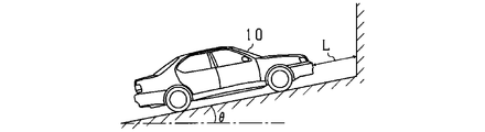
- FIG. 2A is a diagram illustrating a situation in which a vehicle approaches an object on an uphill road.
- FIG. 2B is a diagram illustrating a situation where a vehicle approaches an object on an uphill road.
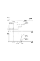
- FIG. 3 is a diagram illustrating a relationship between the driving force instruction value and the vehicle speed.
- FIG. 4 is a flowchart showing processing of driving force suppression control.
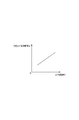
- FIG. 5 is a diagram showing the relationship between the starting time for raising the driving force instruction value and the amount of ascending slope.
- the vehicle control device is mounted on a vehicle (own vehicle) having an engine as a travel drive source.
- the vehicle control device detects an object (obstacle) that exists in front of the traveling direction of the host vehicle, and performs control for avoiding a collision with the object.
- the vehicle 10 includes a vehicle control ECU 20 that is a vehicle control device.
- the vehicle 10 includes various sensors such as a vehicle speed sensor 31, an accelerator sensor 32, an acceleration sensor 33, a shift position sensor 34, and a distance measuring sensor 35. Each sensor 31 to 35 is connected to the vehicle control ECU 20.
- the vehicle speed sensor 31 outputs a pulse signal every predetermined period.
- a method electromechanical pickup method
- a pulse signal is output at a predetermined period when a plurality of convex portions provided on a rotor that rotates together with a wheel pass, and the output pulse signal is detected. Yes.
- the detection result (detected pulse signal) of the vehicle speed sensor 31 is input to the vehicle control ECU 20.
- the vehicle control ECU 20 calculates the vehicle speed based on the pulse interval of the input detection signal.
- the accelerator sensor 32 detects an accelerator opening that indicates whether the accelerator pedal is depressed or not.
- the detection result (accelerator opening information) of the accelerator sensor 32 is input to the vehicle control ECU 20.
- the acceleration sensor 33 detects the acceleration of the vehicle 10 based on the force applied to the sensor itself.
- a capacitance type, a piezoresistive type, or the like is mainly used.
- the acceleration sensor 33 is based on a state in which gravitational acceleration acts vertically on the vehicle 10 stopped on a flat road (horizontal plane). That is, on the uphill road, in a state where the vehicle 10 is stopped with the upward gradient direction as the traveling direction, a value corresponding to the upward gradient amount is detected as the acceleration in the traveling direction in consideration of the gravitational acceleration.
- the detection result of the acceleration sensor 33 (acceleration information of the vehicle 10) is input to the vehicle control ECU 20.
- the shift position sensor 34 detects a shift position (shift range; position of a shift lever for operating a shift state of the transmission) of a shift device (not shown).
- the detection result (current shift position information) of the shift position sensor 34 is input to the vehicle control ECU 20.
- the distance measuring sensor 35 is an ultrasonic sensor.
- the distance measuring sensor 35 receives, for example, an ultrasonic wave of 20 to 100 kHz as a search wave and a search wave reflected from an object as a reflected wave.
- the distance measuring sensor 35 detects an object present around the vehicle 10 based on the reception result of the reflected wave.
- four distance measuring sensors 35 are arranged at predetermined intervals in the vehicle width direction (lateral direction) orthogonal to the traveling direction (vertical direction) of the vehicle 10 in the front part of the vehicle (for example, the front bumper). It is attached.
- two center sensors 35a and 35b are attached to the front portion of the vehicle at positions symmetrical with respect to the center line 11 of the vehicle 10 as an axis of symmetry.
- two corner sensors 35c and 35d are attached to the front portion of the vehicle at positions of the left corner and the right corner, respectively.
- the vehicle 10 is also provided with a distance measuring sensor 35 at the rear of the vehicle (for example, a rear bumper).
- the mounting position and function of the sensor in the rear part of the vehicle are the same as those of the distance measuring sensor 35 in the front part of the vehicle, and the description thereof is omitted here.
- the detection result of the distance measuring sensor 35 is input to the vehicle control ECU 20.
- Vehicle control ECU20 is a computer provided with CPU, memory (for example, ROM and RAM), I / O, etc.
- the vehicle control ECU 20 implements various controls related to vehicle control and driving support by executing a program installed in the ROM, for example (implementing each function described later).
- the vehicle control ECU 20 outputs a control signal for controlling the engine 41 and the brake 42 in order to avoid collision of the vehicle 10 with an object, for example, as control related to driving assistance.
- the vehicle control ECU 20 performs control for suppressing the driving force of the engine 41 when the vehicle 10 approaches the object by moving the vehicle (hereinafter referred to as “driving force suppression control” for convenience). .
- the vehicle control ECU 20 implements the functions of an object determination unit 21, a driving force control unit 22, a gradient calculation unit 23, and a pulling rate change unit 24.
- the object determination unit 21 determines the presence / absence of an object in the vicinity of the vehicle (in the forward direction of the vehicle 10).
- the object determination unit 21 determines the presence / absence of an object around the vehicle based on the object detection information input from the distance measuring sensor 35. Specifically, the object determination unit 21 first transmits a control signal to the distance measuring sensor 35 and transmits a search wave at a transmission period of a predetermined time interval (for example, an interval of 100 milliseconds to several hundred milliseconds). To command.
- a predetermined time interval for example, an interval of 100 milliseconds to several hundred milliseconds.
- the object determination unit 21 determines the presence / absence of an object in front of the vehicle when the vehicle 10 is in a forward movement state (a state in which the vehicle 10 moves forward). On the other hand, the object determination unit 21 determines the presence or absence of an object at the rear of the vehicle when the vehicle 10 is in the reverse state (a state of moving backward).
- the driving force control unit 22 controls the driving force of the engine 41 by changing the driving force instruction value Fi.
- the driving force control unit 22 varies the driving force instruction value Fi with respect to a required value f0 (required driving force from the driver) determined based on the accelerator opening information input from the accelerator sensor 32, whereby the engine 41 is changed.
- the driving force is suppressed.
- the driving force control unit 22 is determined by the object determination unit 21 that an object is present ahead of the traveling direction of the vehicle 10, and a predetermined distance range that is a criterion for determining whether or not the object performs driving force suppression. When it is located inside, the suppression control is performed.
- the driving force control unit 22 requests a driving force instruction value Fi that instructs the driving force of the engine 41 when it is determined that an object is present and the object is located within a predetermined distance.
- the value is smaller than the value f0.
- the driving force suppression of the engine 41 is realized by limiting the intake air amount and the throttle opening, for example.
- the driving force control unit 22 gradually increases the driving force of the engine 41 when the driving force of the engine 41 is restricted and the start of the vehicle 10 is restricted due to the suppression of the driving force.
- the driving force control unit 22 sets the driving force instruction value Fi in a state in which the vehicle speed calculated based on the detection result of the vehicle speed sensor 31 reaches the predetermined speed while suppressing the required value f0. Pull it up gradually (increase the driving force gradually). Further, the driving force control unit 22 lowers the driving force instruction value Fi (the driving force is gradually decreased) after the vehicle speed reaches a predetermined speed.
- FIG. 2A there is a wall in front of the vehicle 10 in the traveling direction, that is, above the upward slope.
- the vehicle 10 and the wall are in proximity.
- the driving force is suppressed because the distance L to the wall is short.
- the start of the vehicle 10 is limited by the upward running resistance.
- the vehicle control ECU 20 gradually increases the driving force instruction value Fi and increases the driving force of the engine 41.
- the stopped vehicle 10 starts on an upward slope, and as shown in FIG. 2B, the vehicle 10 can further reduce the distance L to the wall. Thereafter, when the distance L to the wall becomes shorter than the stop distance, the vehicle 10 is stopped by the brake control.
- the vehicle control ECU 20 is configured to include the gradient calculating unit 23 and the pulling rate changing unit 24.
- the gradient calculation unit 23 calculates the gradient of the travel path of the vehicle 10 (for example, the upward gradient amount ⁇ in the case of an uphill road).
- the raising rate changing unit 24 changes the raising amount with respect to the time taken to raise the driving force instruction value Fi based on the gradient calculated by the gradient calculating unit 23. That is, the pulling rate changing unit 24 changes the pulling rate per time (unit time) based on the gradient. At this time, the raising rate changing unit 24 performs the above change in a state where the driving force instruction value Fi is suppressed with respect to the required value f0 determined based on the accelerator opening.
- the increase rate changing unit 24 increases the time until the drive force instruction value Fi is increased from the initial value f1 as the upward gradient amount ⁇ increases after the start of the suppression of the drive force due to the accelerator being on (the increase start time). Increase Td).
- the raising rate changing unit 24 changes the raising rate of the driving force instruction value Fi. That is, the raising rate changing unit 24 changes the raising rate by changing the timing at which the driving force instruction value Fi is raised from the initial value f1 after the start of driving force suppression.
- the pulling rate changing unit 24 changes the pulling rate to be smaller as the upward gradient amount ⁇ is larger.
- the actual driving force is prevented from deviating from the driving force instruction value Fi. Further, in the present embodiment, the actual driving force at the beginning of raising the driving force instruction value Fi gently increases and changes (rising rise of the driving force becomes gentle).
- the alternate long and short dash line indicates the time change of the driving force instruction value Fi when the pulling start time Td is not changed (when the initial value is maintained).
- the solid line indicates the time change of the driving force instruction value Fi when the pulling start time Td is changed (when it is increased).
- the initial value is smaller than the required value f0 determined from the accelerator opening according to the accelerator operation.
- the driving force instruction value Fi is suppressed to f1.
- the raising start time Td is not changed, the raising of the driving force instruction value Fi is started at the timing t11 when the time Td1 has elapsed.
- the driving force instruction value Fi is pulled up by a predetermined amount (pulling amount) every predetermined cycle (for example, a pulling cycle such as 1 ms), and the vehicle 10 starts moving at timing t13. And after the vehicle 10 starts moving, it accelerates according to the increased driving force.
- raising start time Td when the raising start time Td is changed, raising of the driving force instruction value Fi is started at the timing t12 when the time Td2 has elapsed. Further, after the start of raising, the driving force instruction value Fi is raised by a predetermined amount, and the vehicle 10 starts to move at timing t14. And after the vehicle 10 starts moving, it accelerates according to the increased driving force. Thus, when there is a change in the pulling start time Td, the vehicle 10 starts to move with a smaller driving force instruction value Fi than when there is no change in the pulling start time Td. Therefore, the rise change of the vehicle speed after starting to move becomes gentle.
- the vehicle control ECU 20 determines whether an object has been detected within a predetermined distance in front of the vehicle 10 in the traveling direction (S11). This determination process is performed by the object determination unit 21 included in the vehicle control ECU 20.
- the predetermined distance is one of the criteria (determination values) for determining whether or not to suppress the driving force. When an object is detected within the predetermined distance, the driving force is suppressed. When it is determined that the object is not detected (S11: NO), the vehicle control ECU 20 ends this process.
- the vehicle control ECU 20 determines whether or not the accelerator opening is equal to or greater than the threshold Th1 (S12).
- the threshold value Th1 is one of the criteria (determination value) for determining whether or not to suppress the driving force. When the accelerator opening is equal to or greater than the threshold value Th1, the driving force is suppressed.
- the vehicle control ECU 20 ends this process.
- the vehicle control ECU 20 suppresses the driving force and performs the collision prevention control (S13).
- This suppression control process is performed by the driving force control unit 22 included in the vehicle control ECU 20. Specifically, the driving force control unit 22 sets the driving force instruction value Fi of the engine 41 to a value smaller than the required value f0 determined based on the accelerator opening, and performs the suppression control.
- the driving force instruction value Fi is set to the initial value f1.
- the vehicle control ECU 20 acquires state information of the vehicle 10 (S14).
- the vehicle state information acquired here is information such as a vehicle speed, a shift position, and a road surface gradient.
- the vehicle control ECU 20 acquires vehicle speed information from the vehicle speed sensor 31 and acquires shift position information from the shift position sensor 34.
- the vehicle control ECU 20 acquires road surface gradient information from the acceleration sensor 33.
- the gradient calculation unit 23 calculates the gradient of the travel path of the vehicle 10 based on the detection result of the acceleration sensor 33.
- the vehicle control ECU 20 determines whether or not the traveling path of the vehicle 10 is an uphill road (S15). The determination as to whether or not the road is an uphill road is made by determining whether or not the upward gradient amount ⁇ calculated based on the detection result of the acceleration sensor 33 is equal to or greater than a predetermined upward gradient amount.
- the vehicle control ECU 20 determines whether or not the driving force instruction value Fi is being raised from the initial value f1 (during the raising period of the driving force instruction value Fi) ( S16).
- the vehicle control ECU 20 sets the raising start time Td of the driving force instruction value Fi based on the uphill amount ⁇ of the uphill road (S17).
- This setting process is performed by the pulling rate changing unit 24 of the vehicle control ECU 20.
- the pulling start time Td of the driving force instruction value Fi and the upward gradient amount ⁇ have a relationship as shown in FIG. 5, for example. That is, the pulling rate changing unit 24 sets the pulling start time Td of the driving force command value Fi longer as the uphill amount ⁇ of the uphill road is larger.
- the vehicle control ECU 20 determines whether or not the time until the driving force instruction value Fi is raised from the initial value f1 after the start of driving force suppression has reached the raising start time Td (predetermined timing). (S18). This determination process is performed by the pulling rate changing unit 24. If it is determined that the pull-up time Td has not been reached (S18: NO), the vehicle control ECU 20 ends this process. On the other hand, when it is determined that the pull-up time Td has been reached (S18: YES), the vehicle control ECU 20 determines whether or not the vehicle 10 is in a start restriction state (S19).
- the start restriction state includes, for example, a state in which the vehicle 10 is stopped due to start restriction in the accelerator-on state.
- the vehicle control ECU 20 When it is determined that the vehicle control ECU 20 is not in the start restriction state (S19: NO), the present process is terminated. On the other hand, when it is determined that the vehicle is in the start restricted state (S19: YES), the vehicle control ECU 20 raises the driving force instruction value Fi of the engine 41 (S20), and ends this process.
- the driving force control unit 22 performs this determination process. Specifically, the driving force control unit 22 increases the driving force instruction value Fi by a predetermined amount every predetermined cycle.
- the vehicle control ECU 20 determines whether or not the vehicle speed is equal to or higher than the threshold Th2 (S21). When it is determined that the vehicle speed is smaller than the threshold Th2 (S21: NO), the vehicle control ECU 20 proceeds to the process of step S20 and continues to raise the driving force instruction value Fi. On the other hand, when it is determined that the vehicle speed is equal to or higher than the threshold Th2 (S21: YES), the vehicle control ECU 20 returns the driving force instruction value Fi to the initial value f1 (S22), and ends this process.
- vehicle control device vehicle control ECU 20
- the following excellent effects can be obtained by the above configuration.
- the rate of change of the driving force instruction value Fi increases to the gradient of the travel path. Change based on. That is, in the vehicle control device according to the present embodiment, the pulling rate per hour is changed based on the gradient. For this reason, in a vehicle including the vehicle control device according to the present embodiment, the actual driving force gradually increases. Thereby, in the vehicle control device according to the present embodiment, the actual driving force is prevented from being excessively raised due to the delay in the movement of the vehicle 10 due to the upward gradient. As a result, in the vehicle control device according to the present embodiment, it is possible to avoid a collision with an object while appropriately generating a driving force necessary to start the vehicle 10 in a place with an uphill slope (such as an uphill road).
- an uphill slope such as an uphill road
- the vehicle control apparatus performs control (driving force control) for gradually increasing the driving force of the engine 41 using this change characteristic.
- control driving force control
- the actual increase in driving force can be moderated.
- the desired driving force suppression effect can be obtained while the pulling pattern of the driving force instruction value Fi remains the same. Therefore, in the vehicle control device according to the present embodiment, the configuration for realizing can be simplified.
- the increase start time Td of the driving force instruction value Fi is set longer as the upward gradient amount ⁇ of the road surface is larger, and the pulling rate is reduced. Therefore, in the vehicle control device according to the present embodiment, the actual rising of the driving force (the slope of the rising change) becomes small. As described above, in the vehicle control device according to the present embodiment, even when the start of movement of the vehicle 10 is delayed due to the upward slope, the actual driving force necessary for the start of movement of the vehicle 10 is appropriately generated, Collisions with objects can be avoided.
- the vehicle control device of the present disclosure is not limited to the configuration of the above embodiment. For example, you may change as follows.
- the raising rate changing unit 24 of the vehicle control ECU 20 changes the raising rate by changing the raising start time Td of the driving force instruction value Fi based on the ascending gradient amount ⁇ .
- the raising rate changing unit 24 changes the raising cycle interval Tc when raising the driving force instruction value Fi stepwise based on the ascending gradient amount ⁇ (hereinafter, “configuration (1)”). It may be said.
- the time interval Tc may be increased as the upward gradient amount ⁇ is increased.
- the pulling rate changing unit 24 changes the pulling amount per time when the driving force instruction value Fi is raised stepwise based on the ascending gradient amount ⁇ (hereinafter referred to as “configuration (2)”). ).
- the pulling amount may be increased as the upward gradient amount ⁇ is larger.
- the pulling rate changing unit 24 implements at least one of the configurations (1) and (2).
- the above configuration can suppress the deviation of the actual driving force with respect to the driving force instruction value Fi when the vehicle 10 moves on an ascending slope, as in the above embodiment. Therefore, it is possible to moderate the rise of the actual driving force after the driving force instruction value Fi is raised.
- the pulling rate changing unit 24 may change the pulling rate of the driving force instruction value Fi based on the upward gradient amount ⁇ and the shift position.
- the vehicle control ECU 20 includes a traveling direction determination unit that determines whether the traveling direction of the vehicle 10 is the front of the vehicle or the rear of the vehicle. Based on the shift position information from the shift position sensor 34, the traveling direction determination unit determines the traveling direction of the vehicle 10 based on the determination result whether the current shift position is the drive range or the reverse range. Therefore, the pulling rate changing unit 24 may change the pulling rate according to the determination result of the traveling direction determining unit.
- the pulling rate changing unit 24 changes the pulling rate of the driving force instruction value Fi when the vehicle 10 moves forward and approaches the object and when the vehicle 10 moves backward and approaches the object.
- the driving force instruction value Fi is not caused to make the driver feel uncomfortable in each of the case where the vehicle 10 is moved forward and brought closer to the object and the case where the vehicle 10 is moved backward and brought closer to the object. The rate of increase can be changed appropriately.
Landscapes
- Engineering & Computer Science (AREA)
- Physics & Mathematics (AREA)
- Transportation (AREA)
- Mechanical Engineering (AREA)
- Radar, Positioning & Navigation (AREA)
- Remote Sensing (AREA)
- General Physics & Mathematics (AREA)
- Combustion & Propulsion (AREA)
- Chemical & Material Sciences (AREA)
- Automation & Control Theory (AREA)
- Computer Networks & Wireless Communication (AREA)
- Acoustics & Sound (AREA)
- Mathematical Physics (AREA)
- Control Of Driving Devices And Active Controlling Of Vehicle (AREA)
- Control Of Vehicle Engines Or Engines For Specific Uses (AREA)
- Traffic Control Systems (AREA)
Abstract
車両制御ECU(20)は、車両(10)の進行方向前方における物体の存在有無を判定する判定部(21)と、物体が存在すると判定された場合に、車速が所定速度に達するまでは、運転者が操作したアクセル開度に基づいて定まる要求値に対して抑制した状態で、車両における駆動力指示値を段階的に引き上げ、車速が所定速度に達してから、駆動力指示値を引き下げる制御部(22)と、車両が走行する道路の勾配を算出する算出部(23)と、駆動力指示値を引き上げる際の時間あたりの引き上げ率を、勾配に基づいて変更する変更部(24)と、を備える。
Description
本開示は、車両の進行方向前方に存在する物体を検出して車両を制御する車両制御技術に関する。
従来では、車両に搭載された超音波センサによって、車両周辺に存在する先行車両や歩行者等の物体(障害物)を検出し、検出結果に基づいて、車両の走行安全性を向上させるための各種制御を行うことが提案されている。各種制御としては、例えば、制動装置の作動や運転者への報知等である。
例えば、特許文献1には、車両の進行方向に物体が検出されている場合に、車速が所定速度に達するまでは、駆動力を徐々に引き上げて、車速が所定速度に達してからは、駆動力を引き下げる制御が開示されている。これにより、特許文献1に開示の制御技術では、物体が検出されている場合であっても、物体への衝突を回避し、且つ、車両の発進に必要な駆動力が与えられる。
ところで、車両の進行方向前方に物体が検出されており、車両が登坂路等の上り勾配のある場所を走行する場合は、その勾配により車両の動き出しが遅れることが考えられる。このような場合、従来の制御では、車両が動き出すまでに、駆動力が過剰に増加してしまうことが懸念される。そのため、従来の制御では、車両が動き出してから駆動力を引き下げても、車両の停止が遅れてしまい、車両が物体に達してしまうおそれがある。
本開示は、上り勾配のある場所で、車両の動き出しに必要な駆動力を適正に発生させながら、物体への衝突を回避できる車両制御装置、及び、車両制御装置が実行する車両制御方法を提供することを目的とする。
以下、上記課題を解決するための手段、及びその作用効果について説明する。
本開示における車両制御装置は、車両(10)の進行方向前方における物体の存在有無を判定する物体判定部(21)と、前記物体が存在すると判定された場合に、車速が所定速度に達するまでは、運転者が操作したアクセル開度に基づいて定まる要求値に対して抑制した状態で、前記車両における駆動力指示値を段階的に引き上げ、前記車速が前記所定速度に達してから、前記駆動力指示値を引き下げる駆動力制御部(22)と、前記車両が走行する道路の勾配を算出する勾配算出部(23)と、前記駆動力指示値を引き上げる際の時間あたりの引き上げ率を、前記勾配に基づいて変更する引き上げ率変更部(24)と、を備える。
本開示の車両制御装置は、上記構成により、駆動力指示値の引き上げに伴って実際の駆動力が増加する場合に、駆動力指示値の引き上げの変化率を、走行路の勾配に基づいて変更する。すなわち、本開示の車両制御装置は、時間あたりの引き上げ率を、勾配に基づいて変更する。そのため、本開示の車両制御装置を備える車両では、実際の駆動力が緩やかに増加する。これにより、本開示の車両制御装置では、上り勾配による車両の動き出しの遅れによって、実際の駆動力が過剰に引き上げられることが抑制される。その結果、本開示の車両制御装置では、上り勾配のある場所(登坂路等)で、車両の動き出しに必要な駆動力を適正に発生させながら、物体への衝突を回避できる。
本実施形態に係る車両制御装置は、走行駆動源としてエンジンを有する車両(自車両)に搭載される。車両制御装置は、自車両の進行方向前方に存在する物体(障害物)を検出し、その物体との衝突を回避するための制御を行う。
以下に、本実施形態に係る車両制御装置を適用する車両制御システムの概略構成について、図1を用いて説明する。図1に示すように、車両10は、車両制御装置である車両制御ECU20を備える。また、車両10は、車速センサ31、アクセルセンサ32、加速度センサ33、シフト位置センサ34、及び測距センサ35等の各種センサを備える。各センサ31~35は、車両制御ECU20に接続されている。
車速センサ31は、所定周期ごとにパルス信号を出力する。本実施形態では、車輪と共に回転するロータに設けられた複数の凸部が通過することによって、所定周期でパルス信号が出力され、出力されたパルス信号を検出する方法(電磁ピックアップ方式)を用いている。車速センサ31の検出結果(検出されたパルス信号)は、車両制御ECU20へ入力される。車両制御ECU20は、入力された検出信号のパルス間隔に基づいて、車速を算出する。また、アクセルセンサ32は、アクセルペダルの踏み加減を表すアクセル開度を検出する。アクセルセンサ32の検出結果(アクセル開度情報)は、車両制御ECU20へ入力される。
加速度センサ33は、センサ自身に加わる力に基づいて、車両10の加速度を検出する。加速度センサ33としては、主に、静電容量型やピエゾ抵抗型等が用いられる。加速度センサ33では、平坦路(水平方向の平面)に停車している車両10に対して、垂直に重力加速度が働く状態を基準としている。すなわち、登坂路において、上り勾配方向を進行方向として車両10が停車している状態では、進行方向における加速度として、重力加速度を考慮し上り勾配量に応じた値が検出される。加速度センサ33の検出結果(車両10の加速度情報)は、車両制御ECU20へ入力される。また、シフト位置センサ34は、シフト装置(非図示)のシフト位置(シフトレンジ;変速機の変速状態を操作するシフトレバーの位置)を検出する。シフト位置センサ34の検出結果(現在のシフト位置情報)は、車両制御ECU20へ入力される。
測距センサ35は、超音波センサである。測距センサ35は、例えば20~100kHzの超音波を探査波とし、物体から反射された探査波を反射波として受信する。測距センサ35は、反射波の受信結果に基づいて、車両10の周辺に存在する物体を検出する。本実施形態では、車両前部(例えば前方バンパ)に、4つの測距センサ35が、車両10の進行方向(縦方向)に直交する車幅方向(横方向)に所定の間隔をあけて並べて取り付けられている。具体的には、車両前部には、車両10の中心線11を対称軸として線対称の位置に、2つのセンタセンサ35a,35b(第1センサ35a,第2センサ35b)が取り付けられている。また、車両前部には、左コーナ及び右コーナそれぞれの位置に、2つのコーナセンサ35c,35d(右コーナセンサ35c,左コーナセンサ35d)が取り付けられている。なお、車両10には、車両後部(例えば後方バンパ)にも測距センサ35が取り付けられている。車両後部におけるセンサの取り付け位置及び機能は、車両前部の測距センサ35と同じであるため、ここではその説明を省略する。測距センサ35の検出結果(車両周辺に存在する物体の検出情報)は、車両制御ECU20へ入力される。
車両制御ECU20は、CPU、メモリ(例えばROMやRAM)、及びI/O等を備えたコンピュータである。車両制御ECU20は、CPUが、例えばROMにインストールされているプログラムを実行することにより、車両制御及び運転支援に関する各種制御を実施する(後述する各機能を実現する)。車両制御ECU20は、例えば運転支援に関する制御として、物体に対する車両10の衝突回避を行うために、エンジン41やブレーキ42を制御対象とする制御信号を出力する。
車両制御ECU20は、衝突回避のための機能として、車両移動により、物体に対して車両10が近づく場合にエンジン41の駆動力を抑制する制御(以下便宜上「駆動力抑制制御」という)を実施する。具体的には、車両制御ECU20は、物体判定部21、駆動力制御部22、勾配算出部23、引き上げ率変更部24の各機能を実現する。
物体判定部21は、車両周辺(車両10の進行方向前方)における物体の存在有無を判定する。物体判定部21は、測距センサ35から入力された物体の検出情報に基づいて、車両周辺の物体の有無を判定する。具体的には、物体判定部21は、まず、測距センサ35に制御信号を送信し、所定時間間隔(例えば、100ミリ秒~数100ミリ秒の間隔)の送信周期で探査波を送信するように指令する。そして、物体判定部21は、測距センサ35から物体の検出情報が入力されると、入力された検出情報に基づいて、車両10の進行方向前方における物体の有無を判定する。このとき、物体判定部21は、車両10が前進状態(前方に進む状態)の場合、車両前方における物体の有無を判定する。一方、物体判定部21は、車両10が後退状態(後方に進む状態)の場合、車両後方における物体の有無を判定する。
駆動力制御部22は、駆動力指示値Fiの可変によって、エンジン41の駆動力を制御する。駆動力制御部22は、アクセルセンサ32から入力されたアクセル開度情報に基づき定まる要求値f0(運転者からの要求駆動力)に対して、駆動力指示値Fiを可変させることによって、エンジン41の駆動力抑制を行う。駆動力制御部22は、物体判定部21により、車両10の進行方向前方に物体が存在すると判定され、且つ、その物体が、駆動力抑制を行うか否かの判断基準である所定距離の範囲内に位置する場合に、上記抑制制御を行う。具体的には、駆動力制御部22は、物体が存在すると判定され、且つ、その物体が所定距離の範囲内に位置する場合、エンジン41の駆動力を指示する駆動力指示値Fiを、要求値f0よりも小さい値にする。なお、エンジン41の駆動力抑制は、例えば吸入空気量やスロットル開度を制限することで実現される。
例えば、登坂路等の上り勾配や路面上に段差等がある状況下において、車両移動により、物体に対して車両10が近づく場合を想定する。このような場合に、エンジン41の駆動力抑制が行われると、運転者は物体に対して近づく意思があるにもかかわらず、車両10を移動させることができなくなる。そこで、駆動力制御部22は、エンジン41の駆動力が抑制されている状況下において、その駆動力抑制により、車両10の発進が制限されている場合に、エンジン41の駆動力を徐々に引き上げる制御を実施する。具体的には、駆動力制御部22は、車速センサ31の検出結果に基づいて算出された車速が所定速度に達するまでは、要求値f0に対して抑制した状態で、駆動力指示値Fiを徐々に引き上げる(駆動力を徐々に増加させる)。また、駆動力制御部22は、車速が所定速度に達してからは、駆動力指示値Fiを引き下げる(駆動力を徐々に減少させる)。
以下に、登坂路において、物体に接近しながら車両10を駐車させる状況について、図2A及び図2Bを用いて説明する。図2A及び図2Bでは、車両10が上り勾配量θの勾配面(登坂路)に停車しており、その勾配面を上方に移動する場合を想定している。
図2Aに示すように、車両10の進行方向前方、すなわち上り勾配の上方には壁が存在する。また、車両10と壁とは近接状態にある。このような状況下において、壁に対して車両10をより近づけようとした場合には、壁までの距離Lが短いために、駆動力抑制が行われる。さらに、上り勾配の走行抵抗により、車両10の発進が制限される。このとき、車両制御ECU20は、駆動力指示値Fiを徐々に引き上げ、エンジン41の駆動力を増加させる。これによって、上り勾配に停車中の車両10が発進し、図2Bに示すように、車両10は、壁までの距離Lをさらに縮められる。その後、壁までの距離Lが停止距離よりも短くなった場合には、ブレーキ制御により車両10が停止する。
ところで、車両10の進行方向前方に物体が検出され、その車両10が登坂路等の上り勾配のある場所を走行する場合は、その上り勾配により車両10の動き出しが遅れることが考えられる。このような場合、車両10が動き出すまでの間に行われる駆動力指示値Fiの引き上げに伴って、エンジン41の実際の駆動力が過剰に増加してしまうことが懸念される。
すなわち、登坂路では、上り勾配によって、車両10が動き出すのに必要な駆動力の発生に時間がかかり、駆動力指示値Fiに対して実際の駆動力が乖離した状態となる。このような状態の間に(車両10が動き出すまでの間に)、駆動力指示値Fiがさらに引き上げられた場合には、実際の駆動力が急峻に上昇変化する。その結果、登坂路では、車両10が動き出すまでの間に、実際の駆動力が過剰に増加してしまう。このため、登坂路では、車両10が動き出してから駆動力指示値Fiを引き下げても、車両10の停止が遅れてしまい、車両10が物体に達してしまうおそれがある。
そこで、本実施形態では、車両制御ECU20が、勾配算出部23及び引き上げ率変更部24を有する構成としている。勾配算出部23は、車両10の走行路の勾配(例えば登坂路の場合には上り勾配量θ)を算出する。引き上げ率変更部24は、駆動力指示値Fiを引き上げるのに掛かった時間に対する引き上げ量を、勾配算出部23により算出された勾配に基づいて変更する。すなわち、引き上げ率変更部24は、時間(単位時間)あたりの引き上げ率を、勾配に基づいて変更する。またこのとき、引き上げ率変更部24は、アクセル開度に基づき定まる要求値f0に対して駆動力指示値Fiを抑制した状態において上記変更を行う。具体的には、引き上げ率変更部24は、アクセルオンに伴う駆動力抑制の開始後において、上り勾配量θが大きいほど、駆動力指示値Fiを初期値f1から引き上げるまでの時間(引き上げ開始時間Td)を長くする。これにより、引き上げ率変更部24は、駆動力指示値Fiの引き上げ率を変更する。つまり、引き上げ率変更部24は、駆動力抑制の開始後において、駆動力指示値Fiを初期値f1から引き上げるタイミングを変更することで、引き上げ率を変更する。その中で、引き上げ率変更部24は、上り勾配量θが大きいほど、引き上げ率が小さくなるように変更する。このように、本実施形態では、引き上げ開始時間Tdを長くすることで、駆動力指示値Fiから実際の駆動力が乖離することを抑制する。また、本実施形態では、駆動力指示値Fiの引き上げ開始当初における実際の駆動力が穏やかに上昇変化する(駆動力の増加の立ち上がりが緩やかになる)。
以下に、引き上げ開始時間Tdの変更に伴う駆動力指示値Fiの時間変化と車速の時間変化との関係について、図3を用いて説明する。なお、図3において、一点鎖線は、引き上げ開始時間Tdが変更なしの場合(初期値のままの場合)の駆動力指示値Fiの時間変化を示している。また、実線は、引き上げ開始時間Tdが変更ありの場合(長くした場合)の駆動力指示値Fiの時間変化を示している。
登坂路において、車両10の進行方向前方に物体を検出中の状態で、アクセルがオンになった場合には、そのアクセル操作に応じたアクセル開度から定まる要求値f0より小さい値である初期値f1に駆動力指示値Fiが抑制される。引き上げ開始時間Tdの変更がない場合は、時間Td1が経過したタイミングt11で駆動力指示値Fiの引き上げが開始される。また、引き上げ開始後には、所定周期(例えば1ms等の引き上げ周期)ごとに所定量(引き上げ量)ずつ駆動力指示値Fiが引き上げられ(段階的に引き上げられ)、タイミングt13で車両10が動き出す。そして、車両10が動き出した後には、増加した駆動力に応じて加速する。
一方、引き上げ開始時間Tdの変更がある場合は、時間Td2が経過したタイミングt12で駆動力指示値Fiの引き上げが開始される。また、引き上げ開始後には、所定量ずつ駆動力指示値Fiが引き上げられ、タイミングt14で車両10が動き出す。そして、車両10が動き出した後には、増加した駆動力に応じて加速する。このように、引き上げ開始時間Tdの変更がある場合は、引き上げ開始時間Tdの変更がない場合に比べて、小さい駆動力指示値Fiで車両10が動き出している。よって、動き出した後の車速の立ち上がり変化は緩やかになる。
以下に、車両制御ECU20により実行される駆動力抑制制御の処理手順について、図4を用いて説明する。本処理は、車両制御ECU20により所定周期ごとに実行される。
車両制御ECU20は、車両10の進行方向前方における所定距離の範囲内に、物体を検出したか否かを判定する(S11)。本判定処理は、車両制御ECU20が有する物体判定部21が行う。また、上記所定距離は、駆動力抑制を行うか否かの判断基準(判定値)の1つであり、この所定距離の範囲内に物体を検出した場合に、駆動力抑制が行われる。車両制御ECU20は、物体を検出していないと判定された場合(S11:NO)、本処理を終了する。一方、車両制御ECU20は、物体を検出したと判定された場合(S11:YES)、アクセル開度が閾値Th1以上か否かを判定する(S12)。閾値Th1は、駆動力抑制を行うか否かの判断基準(判定値)の1つであり、アクセル開度が閾値Th1以上の場合に、駆動力抑制が行われる。
車両制御ECU20は、アクセル開度が閾値Th1より小さいと判定された場合(S12:NO)、本処理を終了する。一方、車両制御ECU20は、アクセル開度が閾値Th1以上と判定された場合(S12:YES)、駆動力を抑制し、衝突防止制御を行う(S13)。本抑制制御処理は、車両制御ECU20が有する駆動力制御部22が行う。具体的には、駆動力制御部22は、エンジン41の駆動力指示値Fiを、アクセル開度に基づき定まる要求値f0よりも小さい値にし、上記抑制制御を行う。なお、駆動力指示値Fiの引き上げ期間中でない場合には、駆動力指示値Fiを初期値f1に設定する。
続いて、車両制御ECU20は、車両10の状態情報を取得する(S14)。ここで取得される車両状態情報は、車速やシフト位置、路面勾配等の情報である。車両制御ECU20では、車速センサ31から車速情報を取得し、シフト位置センサ34からシフト位置情報を取得する。また、車両制御ECU20は、加速度センサ33から路面勾配情報を取得する。そして、車両制御ECU20では、勾配算出部23が、加速度センサ33の検出結果に基づいて、車両10の走行路の勾配を算出する。続いて、車両制御ECU20は、車両10の走行路が登坂路か否かを判定する(S15)。登坂路か否かの判定は、加速度センサ33の検出結果に基づいて算出された上り勾配量θが所定の上り勾配量以上か否かの判定により行われる。
車両制御ECU20は、登坂路ではないと判定された場合(S15:NO)、本処理を終了する。一方、車両制御ECU20は、登坂路と判定された場合(S15:YES)、駆動力指示値Fiを初期値f1から引き上げ中(駆動力指示値Fiの引き上げ期間中)か否かを判定する(S16)。
車両制御ECU20は、引き上げ期間中ではないと判定された場合(S16:NO)、登坂路の上り勾配量θに基づいて、駆動力指示値Fiの引き上げ開始時間Tdを設定する(S17)。本設定処理は、車両制御ECU20が有する引き上げ率変更部24が行う。駆動力指示値Fiの引き上げ開始時間Tdと上り勾配量θとは、例えば図5に示すような関係を有している。つまり、引き上げ率変更部24は、登坂路の上り勾配量θが大きいほど、駆動力指示値Fiの引き上げ開始時間Tdを長く設定する。
続いて、車両制御ECU20は、駆動力抑制の開始後において、駆動力指示値Fiを初期値f1から引き上げるまでの時間が、引き上げ開始時間Td(所定のタイミング)に達したか否かを判定する(S18)。本判定処理は、引き上げ率変更部24が行う。車両制御ECU20は、引き上げ時間Tdに達していないと判定された場合(S18:NO)、本処理を終了する。一方、車両制御ECU20は、引き上げ時間Tdに達したと判定された場合(S18:YES)、車両10が発進制限状態か否かを判定する(S19)。なお、当該発進制限状態は、例えば、アクセルオンの状態において、発進制限により車両10が停止している状態等を含む。
車両制御ECU20は、発進制限状態でないと判定された場合(S19:NO)、本処理を終了する。一方、車両制御ECU20は、発進制限状態と判定された場合(S19:YES)、エンジン41の駆動力指示値Fiを引き上げ(S20)、本処理を終了する。本判定処理は、駆動力制御部22が行う。具体的には、駆動力制御部22は、所定周期ごとに所定量ずつ駆動力指示値Fiを引き上げる。
また、車両制御ECU20は、引き上げ期間中と判定された場合(S16:YES)、車速が閾値Th2以上か否かを判定する(S21)。車両制御ECU20は、車速が閾値Th2より小さいと判定された場合(S21:NO)、ステップS20の処理に進み、駆動力指示値Fiの引き上げを継続する。一方、車両制御ECU20は、車速が閾値Th2以上と判定された場合(S21:YES)、駆動力指示値Fiを初期値f1に戻し(S22)、本処理を終了する。
本実施形態に係る車両制御装置(車両制御ECU20)では、上記構成により、以下の優れた効果が得られる。
本実施形態に係る車両制御装置では、エンジン41の駆動力指示値Fiの引き上げに伴って実際の駆動力が増加する場合に、駆動力指示値Fiの引き上げの変化率を、走行路の勾配に基づいて変更する。すなわち、本実施形態に係る車両制御装置では、時間あたりの引き上げ率を、勾配に基づいて変更する。そのため、本実施形態に係る車両制御装置を備える車両では、実際の駆動力が緩やかに増加する。これにより、本実施形態に係る車両制御装置では、上り勾配による車両10の動き出しの遅れによって、実際の駆動力が過剰に引き上げられることが抑制される。その結果、本実施形態に係る車両制御装置では、上り勾配のある場所(登坂路等)で、車両10の動き出しに必要な駆動力を適正に発生させながら、物体への衝突を回避できる。
図3に示したように、駆動力指示値Fiの引き上げ開始時間Td(駆動力指示値Fiを初期値f1から引き上げるタイミング)を変更すると、実際の駆動力の増加の立ち上がり(上昇変化の傾き)が変わる。本実施形態に係る車両制御装置では、この変化特性を利用し、エンジン41の駆動力を徐々に引き上げる制御(駆動力制御)を行う。これにより、本実施形態に係る車両制御装置では、実際の駆動力の増加の立ち上がりを緩やかにできる。また、本実施形態に係る車両制御装置では、実際の駆動力を増加させる上で、駆動力指示値Fiの引き上げパターンは同じままで、所望の駆動力抑制の効果が得られる。そのため、本実施形態に係る車両制御装置では、実現するための構成の簡易化が図れる。
車両10の走行路が登坂路の場合には、路面の上り勾配量θが大きいほど、駆動力指示値Fiの引き上げ開始時間Tdを長く設定し、引き上げ率を小さくする。そのため、本実施形態に係る車両制御装置では、実際の駆動力の増加の立ち上がり(上昇変化の傾き)が小さくなる。以上のように、本実施形態に係る車両制御装置では、上り勾配により車両10の動き出しの遅れが生じる場合であっても、車両10の動き出しに必要な実際の駆動力を適正に発生させながら、物体への衝突を回避できる。
(他実施形態)
本開示の車両制御装置は、上記実施形態の構成に限定されない。例えば次のように変更してもよい。
本開示の車両制御装置は、上記実施形態の構成に限定されない。例えば次のように変更してもよい。
・上記実施形態では、駆動力指示値Fiの引き上げ率を上り勾配量θに基づいて変更する構成について説明を行った。その中で、車両制御ECU20が有する引き上げ率変更部24は、上り勾配量θに基づいて、駆動力指示値Fiの引き上げ開始時間Tdを変化させることで、引き上げ率を変更しているが、この限りでない。変形例では、引き上げ率変更部24が、駆動力指示値Fiを段階的に引き上げていく際の引き上げ周期の間隔Tcを、上り勾配量θに基づいて変更する構成(以下「構成(1)」という)としてもよい。構成(1)では、上り勾配量θが大きいほど、時間間隔Tcを大きくすればよい。また、引き上げ率変更部24が、駆動力指示値Fiを段階的に引き上げていく際の1回あたりの引き上げ量を、上り勾配量θに基づいて変更する構成(以下「構成(2)」という)としてもよい。構成(2)では、上り勾配量θが大きいほど、引き上げ量を大きくすればよい。このように、変形例では、引き上げ率変更部24が、上記構成(1)及び(2)の少なくともいずれかを実施する。
本変形例では、上記構成により、上記実施形態と同様に、車両10が上り勾配を移動する場合において、駆動力指示値Fiに対する実際の駆動力の乖離を抑制できる。よって、駆動力指示値Fiの引き上げ後における実際の駆動力の増加の立ち上がりを緩やかにできる。
・別の変形例では、引き上げ率変更部24が、上り勾配量θ及びシフト位置に基づいて、駆動力指示値Fiの引き上げ率を変更するようにしてもよい。別の変形例では、車両制御ECU20は、車両10の進行方向が、車両前方か、又は、車両後方かを判定する進行方向判定部を備える。進行方向判定部は、シフト位置センサ34からのシフト位置情報に基づいて、現在のシフト位置が、ドライブレンジか、又は、リバースレンジかの判定結果に基づいて、車両10の進行方向を判定する。よって、引き上げ率変更部24は、進行方向判定部の判定結果に応じて、引き上げ率を変更すればよい。
このように、別の変形例では、引き上げ率変更部24が、車両10を前進させて物体に近づける場合と、後退させて物体に近づける場合とで、駆動力指示値Fiの引き上げ率をそれぞれ変更する。別の変形例では、上記構成により、車両10を前進させて物体に近づける場合と、後退させて物体に近づける場合とのそれぞれにおいて、運転者に違和感を感じさせることなく、駆動力指示値Fiの引き上げ率の変更を適正に行える。
10…車両、20…車両制御ECU、21…物体判定部、22…駆動力制御部、23…勾配算出部、24…引き上げ率変更部。
Claims (5)
- 車両(10)の進行方向前方における物体の存在有無を判定する物体判定部(21)と、
前記物体が存在すると判定された場合に、車速が所定速度に達するまでは、運転者が操作したアクセル開度に基づいて定まる要求値に対して抑制した状態で、前記車両における駆動力指示値を段階的に引き上げ、前記車速が前記所定速度に達してから、前記駆動力指示値を引き下げる駆動力制御部(22)と、
前記車両が走行する道路の勾配を算出する勾配算出部(23)と、
前記駆動力指示値を引き上げる際の時間あたりの引き上げ率を、前記勾配に基づいて変更する引き上げ率変更部(24)と、
を備える、車両制御装置。 - 前記駆動力制御部は、前記物体が存在すると判定された場合に、前記車速が前記所定速度に達するまでは、前記駆動力指示値を、前記要求値より小さい駆動力である初期値から段階的に引き上げ、
前記引き上げ率変更部は、駆動力抑制の開始後において、前記駆動力指示値を前記初期値から引き上げるタイミングを変更することで、前記引き上げ率を変更する、請求項1に記載の車両制御装置。 - 前記引き上げ率変更部は、前記勾配の上り勾配量が大きいほど、前記引き上げ率を小さくする、請求項1又は2に記載の車両制御装置。
- 前記物体が存在すると判定された場合において、前記車両の進行方向が、車両前方か、又は、車両後方かを判定する進行方向判定部を備え、
前記引き上げ率変更部は、前記進行方向判定部の判定結果に応じて、前記引き上げ率を変更する、請求項1乃至3のいずれか1項に記載の車両制御装置。 - 車両制御装置(20)が実行する車両制御方法であって、
車両(10)の進行方向前方における物体の存在有無を判定するステップと、
前記物体が存在すると判定された場合に、車速が所定速度に達するまでは、運転者が操作したアクセル開度に基づいて定まる要求値に対して抑制した状態で、前記車両における駆動力指示値を段階的に引き上げ、前記車速が前記所定速度に達してから、前記駆動力指示値を引き下げるステップと、
前記車両が走行する道路の勾配を算出するステップと、
前記駆動力指示値を引き上げる際の時間あたりの引き上げ率を、前記勾配に基づいて変更するステップと、
を含む、車両制御方法。
Priority Applications (3)
| Application Number | Priority Date | Filing Date | Title |
|---|---|---|---|
| DE112016003017.7T DE112016003017B4 (de) | 2015-06-30 | 2016-06-07 | Fahrzeugsteuervorrichtung und fahrzeugsteuerverfahren |
| US15/740,599 US10864907B2 (en) | 2015-06-30 | 2016-06-07 | Vehicle control device and vehicle control method |
| CN201680037649.8A CN107709121B (zh) | 2015-06-30 | 2016-06-07 | 车辆控制装置以及车辆控制方法 |
Applications Claiming Priority (2)
| Application Number | Priority Date | Filing Date | Title |
|---|---|---|---|
| JP2015-131131 | 2015-06-30 | ||
| JP2015131131A JP6378139B2 (ja) | 2015-06-30 | 2015-06-30 | 車両制御装置及び車両制御方法 |
Publications (1)
| Publication Number | Publication Date |
|---|---|
| WO2017002553A1 true WO2017002553A1 (ja) | 2017-01-05 |
Family
ID=57608547
Family Applications (1)
| Application Number | Title | Priority Date | Filing Date |
|---|---|---|---|
| PCT/JP2016/066919 Ceased WO2017002553A1 (ja) | 2015-06-30 | 2016-06-07 | 車両制御装置及び車両制御方法 |
Country Status (5)
| Country | Link |
|---|---|
| US (1) | US10864907B2 (ja) |
| JP (1) | JP6378139B2 (ja) |
| CN (1) | CN107709121B (ja) |
| DE (1) | DE112016003017B4 (ja) |
| WO (1) | WO2017002553A1 (ja) |
Cited By (1)
| Publication number | Priority date | Publication date | Assignee | Title |
|---|---|---|---|---|
| CN107424424A (zh) * | 2017-01-22 | 2017-12-01 | 斑马信息科技有限公司 | 基于车辆的车前路况的辅助驾驶系统和辅助驾驶方法以及车辆 |
Families Citing this family (4)
| Publication number | Priority date | Publication date | Assignee | Title |
|---|---|---|---|---|
| KR101795182B1 (ko) * | 2015-12-14 | 2017-11-07 | 현대자동차주식회사 | 급경사로에서 차량의 시동 꺼짐 방지를 위한 엔진 제어 방법 |
| JP7230492B2 (ja) * | 2018-12-21 | 2023-03-01 | トヨタ自動車株式会社 | 車両走行支援装置 |
| JP7172934B2 (ja) * | 2019-09-24 | 2022-11-16 | いすゞ自動車株式会社 | 車両制御装置 |
| US11505176B2 (en) | 2020-06-30 | 2022-11-22 | Rivian Ip Holdings, Llc | Systems and methods for controlling torque induced yaw in a vehicle |
Citations (3)
| Publication number | Priority date | Publication date | Assignee | Title |
|---|---|---|---|---|
| JP2007008333A (ja) * | 2005-06-30 | 2007-01-18 | Nissan Motor Co Ltd | 先行車追従制御装置 |
| JP2008150006A (ja) * | 2006-12-20 | 2008-07-03 | Hitachi Ltd | 車両駆動力制御装置 |
| JP2014091351A (ja) * | 2012-10-31 | 2014-05-19 | Toyota Motor Corp | 運転支援装置 |
Family Cites Families (5)
| Publication number | Priority date | Publication date | Assignee | Title |
|---|---|---|---|---|
| JP4386082B2 (ja) * | 2007-02-20 | 2009-12-16 | トヨタ自動車株式会社 | 車両走行支援装置 |
| JP5168416B2 (ja) * | 2011-02-18 | 2013-03-21 | トヨタ自動車株式会社 | 車両用制御システム |
| JP5542178B2 (ja) * | 2012-07-18 | 2014-07-09 | 富士重工業株式会社 | 車両の駆動力抑制装置 |
| WO2014083763A1 (ja) * | 2012-11-27 | 2014-06-05 | 日産自動車株式会社 | 車両用加速抑制装置及び車両用加速抑制方法 |
| RU2699204C1 (ru) * | 2015-11-09 | 2019-09-03 | Ниссан Мотор Ко., Лтд. | Способ управления тормозной/движущей силой и устройство управления тормозной/движущей силой |
-
2015
- 2015-06-30 JP JP2015131131A patent/JP6378139B2/ja active Active
-
2016
- 2016-06-07 CN CN201680037649.8A patent/CN107709121B/zh active Active
- 2016-06-07 WO PCT/JP2016/066919 patent/WO2017002553A1/ja not_active Ceased
- 2016-06-07 US US15/740,599 patent/US10864907B2/en active Active
- 2016-06-07 DE DE112016003017.7T patent/DE112016003017B4/de active Active
Patent Citations (3)
| Publication number | Priority date | Publication date | Assignee | Title |
|---|---|---|---|---|
| JP2007008333A (ja) * | 2005-06-30 | 2007-01-18 | Nissan Motor Co Ltd | 先行車追従制御装置 |
| JP2008150006A (ja) * | 2006-12-20 | 2008-07-03 | Hitachi Ltd | 車両駆動力制御装置 |
| JP2014091351A (ja) * | 2012-10-31 | 2014-05-19 | Toyota Motor Corp | 運転支援装置 |
Cited By (1)
| Publication number | Priority date | Publication date | Assignee | Title |
|---|---|---|---|---|
| CN107424424A (zh) * | 2017-01-22 | 2017-12-01 | 斑马信息科技有限公司 | 基于车辆的车前路况的辅助驾驶系统和辅助驾驶方法以及车辆 |
Also Published As
| Publication number | Publication date |
|---|---|
| US20180154890A1 (en) | 2018-06-07 |
| JP6378139B2 (ja) | 2018-08-22 |
| DE112016003017B4 (de) | 2023-06-07 |
| US10864907B2 (en) | 2020-12-15 |
| CN107709121A (zh) | 2018-02-16 |
| DE112016003017T5 (de) | 2018-03-15 |
| JP2017013598A (ja) | 2017-01-19 |
| CN107709121B (zh) | 2020-07-28 |
Similar Documents
| Publication | Publication Date | Title |
|---|---|---|
| US11001255B2 (en) | Driving assistance apparatus and driving assistance method | |
| JP6502662B2 (ja) | 車両制御装置 | |
| JP6859902B2 (ja) | 車両制御装置 | |
| JP5915152B2 (ja) | 走行支援装置及び走行支援方法 | |
| JP6152673B2 (ja) | 車線変更支援装置 | |
| JP6981196B2 (ja) | 車両の走行支援装置 | |
| JP6397248B2 (ja) | 車両用走行支援装置 | |
| WO2017002553A1 (ja) | 車両制御装置及び車両制御方法 | |
| CN106476800A (zh) | 碰撞避免辅助装置 | |
| US11827221B2 (en) | Vehicle and vehicle control method | |
| WO2019102772A1 (ja) | 車両の制動支援装置、制御装置及び制動支援方法 | |
| JP2017117345A (ja) | 運転支援装置及び運転支援方法 | |
| JP2017114427A5 (ja) | ||
| JP2003112618A (ja) | 車両用制動制御装置 | |
| CN109435948B (zh) | 车辆控制装置和控制方法 | |
| JP2010137803A (ja) | 車両用運転支援装置 | |
| WO2014192368A1 (ja) | 車両の制御装置及び車両の走行制御システム | |
| JP2012192862A (ja) | 車両制御装置 | |
| JP6347242B2 (ja) | 車両の制御装置 | |
| CN111252065A (zh) | 驾驶辅助装置 | |
| WO2017002668A1 (ja) | 車両制御装置、及び車両制御方法 | |
| JP4624726B2 (ja) | 車間距離制御装置 | |
| JP2020077065A (ja) | 車両制御装置 | |
| JP2015137575A (ja) | 車両用制御装置 |
Legal Events
| Date | Code | Title | Description |
|---|---|---|---|
| 121 | Ep: the epo has been informed by wipo that ep was designated in this application |
Ref document number: 16817662 Country of ref document: EP Kind code of ref document: A1 |
|
| WWE | Wipo information: entry into national phase |
Ref document number: 15740599 Country of ref document: US |
|
| WWE | Wipo information: entry into national phase |
Ref document number: 112016003017 Country of ref document: DE |
|
| 122 | Ep: pct application non-entry in european phase |
Ref document number: 16817662 Country of ref document: EP Kind code of ref document: A1 |