WO2016208179A1 - 回転子 - Google Patents
回転子 Download PDFInfo
- Publication number
- WO2016208179A1 WO2016208179A1 PCT/JP2016/002966 JP2016002966W WO2016208179A1 WO 2016208179 A1 WO2016208179 A1 WO 2016208179A1 JP 2016002966 W JP2016002966 W JP 2016002966W WO 2016208179 A1 WO2016208179 A1 WO 2016208179A1
- Authority
- WO
- WIPO (PCT)
- Prior art keywords
- inner core
- wall surfaces
- rotor
- axial direction
- impeller
- Prior art date
- Legal status (The legal status is an assumption and is not a legal conclusion. Google has not performed a legal analysis and makes no representation as to the accuracy of the status listed.)
- Ceased
Links
Images

Classifications
-
- F—MECHANICAL ENGINEERING; LIGHTING; HEATING; WEAPONS; BLASTING
- F04—POSITIVE - DISPLACEMENT MACHINES FOR LIQUIDS; PUMPS FOR LIQUIDS OR ELASTIC FLUIDS
- F04D—NON-POSITIVE-DISPLACEMENT PUMPS
- F04D29/00—Details, component parts, or accessories
- F04D29/18—Rotors
- F04D29/20—Mounting rotors on shafts
-
- F—MECHANICAL ENGINEERING; LIGHTING; HEATING; WEAPONS; BLASTING
- F02—COMBUSTION ENGINES; HOT-GAS OR COMBUSTION-PRODUCT ENGINE PLANTS
- F02M—SUPPLYING COMBUSTION ENGINES IN GENERAL WITH COMBUSTIBLE MIXTURES OR CONSTITUENTS THEREOF
- F02M37/00—Apparatus or systems for feeding liquid fuel from storage containers to carburettors or fuel-injection apparatus; Arrangements for purifying liquid fuel specially adapted for, or arranged on, internal-combustion engines
- F02M37/04—Feeding by means of driven pumps
- F02M37/08—Feeding by means of driven pumps electrically driven
-
- F—MECHANICAL ENGINEERING; LIGHTING; HEATING; WEAPONS; BLASTING
- F04—POSITIVE - DISPLACEMENT MACHINES FOR LIQUIDS; PUMPS FOR LIQUIDS OR ELASTIC FLUIDS
- F04D—NON-POSITIVE-DISPLACEMENT PUMPS
- F04D13/00—Pumping installations or systems
- F04D13/02—Units comprising pumps and their driving means
- F04D13/06—Units comprising pumps and their driving means the pump being electrically driven
-
- F—MECHANICAL ENGINEERING; LIGHTING; HEATING; WEAPONS; BLASTING
- F04—POSITIVE - DISPLACEMENT MACHINES FOR LIQUIDS; PUMPS FOR LIQUIDS OR ELASTIC FLUIDS
- F04D—NON-POSITIVE-DISPLACEMENT PUMPS
- F04D29/00—Details, component parts, or accessories
- F04D29/04—Shafts or bearings, or assemblies thereof
- F04D29/043—Shafts
-
- F—MECHANICAL ENGINEERING; LIGHTING; HEATING; WEAPONS; BLASTING
- F04—POSITIVE - DISPLACEMENT MACHINES FOR LIQUIDS; PUMPS FOR LIQUIDS OR ELASTIC FLUIDS
- F04D—NON-POSITIVE-DISPLACEMENT PUMPS
- F04D29/00—Details, component parts, or accessories
- F04D29/18—Rotors
- F04D29/181—Axial flow rotors
-
- F—MECHANICAL ENGINEERING; LIGHTING; HEATING; WEAPONS; BLASTING
- F04—POSITIVE - DISPLACEMENT MACHINES FOR LIQUIDS; PUMPS FOR LIQUIDS OR ELASTIC FLUIDS
- F04D—NON-POSITIVE-DISPLACEMENT PUMPS
- F04D29/00—Details, component parts, or accessories
- F04D29/40—Casings; Connections of working fluid
- F04D29/52—Casings; Connections of working fluid for axial pumps
- F04D29/528—Casings; Connections of working fluid for axial pumps especially adapted for liquid pumps
-
- F—MECHANICAL ENGINEERING; LIGHTING; HEATING; WEAPONS; BLASTING
- F04—POSITIVE - DISPLACEMENT MACHINES FOR LIQUIDS; PUMPS FOR LIQUIDS OR ELASTIC FLUIDS
- F04D—NON-POSITIVE-DISPLACEMENT PUMPS
- F04D3/00—Axial-flow pumps
- F04D3/005—Axial-flow pumps with a conventional single stage rotor
-
- F—MECHANICAL ENGINEERING; LIGHTING; HEATING; WEAPONS; BLASTING
- F04—POSITIVE - DISPLACEMENT MACHINES FOR LIQUIDS; PUMPS FOR LIQUIDS OR ELASTIC FLUIDS
- F04D—NON-POSITIVE-DISPLACEMENT PUMPS
- F04D5/00—Pumps with circumferential or transverse flow
- F04D5/002—Regenerative pumps
-
- H—ELECTRICITY
- H02—GENERATION; CONVERSION OR DISTRIBUTION OF ELECTRIC POWER
- H02K—DYNAMO-ELECTRIC MACHINES
- H02K1/00—Details of the magnetic circuit
- H02K1/06—Details of the magnetic circuit characterised by the shape, form or construction
- H02K1/22—Rotating parts of the magnetic circuit
-
- H—ELECTRICITY
- H02—GENERATION; CONVERSION OR DISTRIBUTION OF ELECTRIC POWER
- H02K—DYNAMO-ELECTRIC MACHINES
- H02K1/00—Details of the magnetic circuit
- H02K1/06—Details of the magnetic circuit characterised by the shape, form or construction
- H02K1/22—Rotating parts of the magnetic circuit
- H02K1/27—Rotor cores with permanent magnets
- H02K1/2706—Inner rotors
- H02K1/272—Inner rotors the magnetisation axis of the magnets being perpendicular to the rotor axis
- H02K1/2726—Inner rotors the magnetisation axis of the magnets being perpendicular to the rotor axis the rotor consisting of a single magnet or two or more axially juxtaposed single magnets
- H02K1/2733—Annular magnets
-
- H—ELECTRICITY
- H02—GENERATION; CONVERSION OR DISTRIBUTION OF ELECTRIC POWER
- H02K—DYNAMO-ELECTRIC MACHINES
- H02K5/00—Casings; Enclosures; Supports
- H02K5/04—Casings or enclosures characterised by the shape, form or construction thereof
- H02K5/12—Casings or enclosures characterised by the shape, form or construction thereof specially adapted for operating in liquid or gas
-
- H—ELECTRICITY
- H02—GENERATION; CONVERSION OR DISTRIBUTION OF ELECTRIC POWER
- H02K—DYNAMO-ELECTRIC MACHINES
- H02K7/00—Arrangements for handling mechanical energy structurally associated with dynamo-electric machines, e.g. structural association with mechanical driving motors or auxiliary dynamo-electric machines
- H02K7/04—Balancing means
-
- H—ELECTRICITY
- H02—GENERATION; CONVERSION OR DISTRIBUTION OF ELECTRIC POWER
- H02K—DYNAMO-ELECTRIC MACHINES
- H02K7/00—Arrangements for handling mechanical energy structurally associated with dynamo-electric machines, e.g. structural association with mechanical driving motors or auxiliary dynamo-electric machines
- H02K7/14—Structural association with mechanical loads, e.g. with hand-held machine tools or fans
Definitions
- This disclosure relates to a rotor used in a motor that drives an impeller of a fuel pump.
- the rotor of the motor includes a rotating shaft, an inner core that fits the rotating shaft, and a bonded magnet that covers the inner core.
- a bond magnet consists of a neodymium bond magnet etc., for example, and has a cylinder part and the top plate and bottom board which block
- the deviation in the dynamic balance of the rotor due to the D-shaped cross-sectional shape of the end of the rotating shaft is corrected by the concave or convex portions of the top plate and the bottom plate.
- Patent Document 1 the volume of the bonded magnet is reduced by providing an inner core. For this reason, the amount of materials such as rare earth metals constituting the bonded magnet is reduced. On the other hand, with the recent increase in demand, the scarcity of the above materials is increasing, and in order to reduce the amount of materials used as much as possible, it is required to further reduce the volume of the bond magnet.
- the cylinder part which comprises the magnetic pole of a rotor cannot be reduced, it is possible to reduce a top plate and a bottom plate. However, if the top plate and the bottom plate are reduced, there is a problem that the dynamic balance cannot be corrected. If a concave portion or the like for correcting the dynamic balance is provided at the end of the cylindrical portion, the thickness of the cylindrical portion must be increased, which is contrary to reducing the volume of the bond magnet.
- the present disclosure has been made in view of the above points, and an object thereof is to provide a rotor in which the volume of the bond magnet is reduced without deteriorating the dynamic balance.
- one aspect of the present disclosure is a rotor used in a motor that rotationally drives an impeller of a fuel pump, and includes a cylindrical bond magnet that forms a plurality of magnetic poles, and an inner side of the bond magnet A cylindrical inner core, and a rotating shaft provided so as to penetrate the inner side of the inner core.
- the inner core has both axial end faces exposed to the outside.
- the rotating shaft has a connecting end that fits into the impeller.
- the connecting end portion forms a pair of planes parallel to each other, and the centroid of the cross section coincides with the rotational axis.
- the bonded magnet can be configured only from the cylindrical portion.
- the bonded magnet composed only of the cylindrical portion has a smaller volume than the conventional magnet composed of the cylindrical portion, the top plate, and the bottom plate because there is no top plate and bottom plate. Therefore, the volume of the bonded magnet can be reduced without deteriorating the dynamic balance.
- FIG. 2 is a sectional view taken along line II-II in FIG. It is a figure which shows the impeller of FIG. It is a figure which shows the rotor of FIG.
- FIG. 5 is a cross-sectional view taken along line VV in FIG. 4.
- FIG. 6 is a sectional view taken along line VI-VI in FIG. 4. It is an enlarged view of the VII part of FIG.
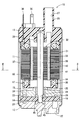
- the fuel pump to which the rotor according to the first embodiment is applied is an in-tank type pump installed in a fuel tank of a vehicle, and sucks fuel from a suction passage 22 shown in the lower part of FIG. From the discharge flow path 27 shown in the upper part of FIG.
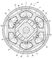
- the fuel pump 10 includes a cylindrical housing 11, a suction side cover 12 provided at one end of the housing 11, a discharge side cover 13 provided at the other end of the housing 11, and suction inside the housing 11.
- a bottomed cylindrical casing 15 that forms a pump chamber 14 between the side cover 12, an impeller 16 that is provided in the pump chamber 14, and a motor that is provided in the housing 11 and that rotates the impeller 16. 17.
- the suction side cover 12 has a suction side pressurizing channel 21 and a suction channel 22.
- the suction side pressurizing flow path 21 is formed in a wall portion facing the impeller 16 among the inner walls defining the pump chamber 14.
- the suction side pressurizing flow path 21 is a C-shaped groove extending in the circumferential direction.
- the suction channel 22 is formed so as to penetrate from the upstream end of the suction side boost channel 21 to the outside.
- the casing 15 has a discharge-side boost channel 23 and a discharge hole 24.
- the discharge-side pressurizing flow path 23 is formed in a wall portion facing the impeller 16 among the inner walls that define the pump chamber 14.
- the discharge side pressurizing flow path 23 is a C-shaped groove extending in the circumferential direction.
- the discharge hole 24 is formed so as to penetrate from the downstream end portion of the discharge side pressurizing flow path 23 to the motor 17 side.
- a bearing 25 is provided at the center of the casing 15.
- the discharge side cover 13 forms a cylindrical portion 26 that protrudes to the outside.
- the cylindrical portion 26 has a discharge flow path 27 that penetrates from the inside of the housing 11 toward the outside.
- a bearing 28 is provided at the center of the discharge side cover 13.
- the impeller 16 is a disk-shaped impeller.
- a fitting hole 29 is formed in the center of the impeller 16.
- the fitting hole 29 has the same cross-sectional shape as a connection end portion 39 to be described later, and is formed slightly larger than the connection end portion 39.
- the motor 17 includes a stator 31 fixed to the housing 11 and a rotor 32 provided inside the stator 31.
- the stator 31 has a stator core 33, an insulator 34, a winding 35 and a terminal 36.
- a fuel flow path 37 is defined between the housing 11 and the stator 31.
- the fuel flow path 37 communicates with the discharge flow path 27 through a fuel flow path (not shown).
- a rotating shaft 38 of the rotor 32 is rotatably supported by bearings 25 and 28.
- the connection end 39 of the rotating shaft 38 is fitted in the fitting hole 29 of the impeller 16.
- the rotation shaft 38 is connected to the impeller 16 so as to be able to transmit rotation.
- the fuel pump 10 configured as described above, when the motor 17 is operated and the impeller 16 is rotated, fuel is sucked into the pump chamber 14 via the suction passage 22 from, for example, a fuel tank or the like.
- the fuel in the pump chamber 14 flows in a spiral manner between the impeller 16 and the pressure increasing channels 21, 23, and the pressure is increased from the suction channel 22 toward the discharge hole 24.
- the pressurized fuel is discharged from the discharge passage 27 to the outside through the discharge hole 24, the fuel passage 37, and the like.
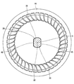
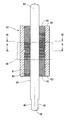
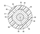
- the rotor 32 is provided so as to penetrate through a cylindrical bonded magnet 41 constituting a plurality of magnetic poles, a cylindrical inner core 42 provided inside the bonded magnet 41, and the inner core 42. And a rotation shaft 38.
- the magnetic poles are provided so that the radially outer polarities are alternately different in the circumferential direction. A portion of the rotor 32 exposed to the internal space of the housing 11 is exposed to fuel during use of the fuel pump 10.
- the bonded magnet 41 is composed only of a cylindrical portion and does not block both end faces 43 and 44 of the inner core 42. That is, the one end surface 43 and the other end surface 44 of the inner core 42 are exposed to the outside.
- the connecting end 39 of the rotating shaft 38 forms a pair of planes 45 parallel to each other, and the centroid G of the cross section coincides with the rotating shaft AX.
- the inner core 42 has a recess 46 that is recessed radially inward in a cross section parallel to the axial direction.
- the bond magnet 41 has a convex portion 47 that protrudes into the concave portion 46 and engages with the concave portion 46 in the axial direction. The bond magnet 41 is prevented from coming off from the inner core 42 by the convex portion 47 engaging the concave portion 46.
- the recess 46 corresponds to “an engaged portion”.
- the convex portion 47 corresponds to an “engagement portion”.
- the concave portions 46 are provided at a plurality of locations in the circumferential direction.
- the inner core 42 has a quadrangular cross-sectional shape.
- the recesses 46 are provided at four locations corresponding to the corners of the rectangle.
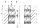
- the inner core 42 is composed of a plurality of metal plates stacked in the axial direction.
- the plurality of metal plates are a first metal plate 48 that forms the bottom of the recess 46 and a second metal plate 49 that is provided on both sides in the axial direction with respect to the first metal plate 48.
- the inner core 42 is configured by combining a laminated body composed of a plurality of second metal plates 49, a laminated body composed of a plurality of first metal plates 48, and a laminated body composed of a plurality of second metal plates 49. Yes.
- the one end surface 43 of the inner core 42 is on the same plane as the one end surface 52 of the bond magnet 41.
- the other end surface 44 of the inner core 42 is on the same plane as the other end surface 54 of the bonded magnet 41.
- the first metal plate 48 includes four first outer wall surfaces 55 corresponding to the bottom portion of the recess 46 and four second outer wall surfaces 56 positioned between the first outer wall surfaces 55.
- the first outer wall surface 55 is a curved surface corresponding to the aforementioned square corner.
- the second outer wall surface 56 is a plane corresponding to the aforementioned rectangular side.
- the second metal plate 49 has four third outer wall surfaces 57 positioned radially outward with respect to the first outer wall surface 55, and 4 positioned on the same plane as the second outer wall surface 56. And a fourth outer wall surface 58.
- the third outer wall surface 57 is a curved surface corresponding to the aforementioned square corner.
- the fourth outer wall surface 58 is a plane corresponding to the aforementioned rectangular side.
- the second outer wall surfaces 56 are provided at equal intervals in the circumferential direction. The second outer wall surface 56 is used as a reference when the rotary shaft 38 is press-fitted into the laminated metal plates 48 and 49 together with the fourth outer wall surface 58 on the same plane.
- the inner core 42 has both end faces 43 and 44 in the axial direction exposed to the outside.
- the rotating shaft 38 has a connection end 39 that fits into the impeller 16.
- the connecting end 39 forms a pair of planes 45 parallel to each other, and the centroid G of the cross section coincides with the rotational axis AX.
- the bond magnet 41 can be configured only from the cylindrical portion.
- the bonded magnet 41 consisting only of the cylindrical portion has a smaller volume than the conventional magnet consisting of the cylindrical portion, the top plate, and the bottom plate due to the absence of the top plate and the bottom plate. Therefore, the volume of the bond magnet 41 can be reduced without deteriorating the dynamic balance.
- the inner core 42 has a recess 46 that is recessed radially inward in a cross section parallel to the axial direction.
- the bond magnet 41 has a convex portion 47 that engages with the concave portion 46 in the axial direction. Therefore, even if the bonding force between the bond magnet 41 and the inner core 42 is lost, it is possible to avoid the bond magnet 41 from moving in the axial direction with respect to the inner core 42 by engaging the convex portion 47 with the concave portion 46.
- the recesses 46 are provided at a plurality of locations in the circumferential direction.
- the inner core 42 is composed of a plurality of metal plates stacked in the axial direction.
- the plurality of metal plates are a first metal plate 48 that forms the bottom of the recess 46 and a second metal plate 49 that is provided on both sides in the axial direction with respect to the first metal plate 48.
- the first metal plate 48 has a plurality of first outer wall surfaces 55 corresponding to the bottom of the recess 46 and a plurality of second outer wall surfaces 56 positioned between the plurality of first outer wall surfaces 55.
- the second metal plate 49 includes a plurality of third outer wall surfaces 57 positioned radially outward with respect to the first outer wall surface 55, and a plurality of fourth outer wall surfaces 58 positioned on the same plane as the second outer wall surface 56.
- first outer wall surfaces 56 are provided.
- the second outer wall surfaces 56 are provided at equal intervals in the circumferential direction. Therefore, when the rotary shaft 38 is press-fitted into the laminated metal plates 48 and 49, if the four second outer wall surfaces 56 are held, the movement of the first metal plate 48 can be reliably restricted.
- the one end surface 43 of the inner core 42 is on the same plane as the one end surface 52 of the bond magnet 41.
- the other end surface 44 of the inner core 42 is on the same plane as the other end surface 54 of the bonded magnet 41. Therefore, the fuel can be prevented from penetrating the inner core 42, that is, between the respective metal plates, and the corrosion of the inner core 42 can be suppressed.
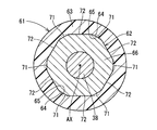
- the rotor 61 includes a rotation shaft 38, an inner core 62, and a bond magnet 63.
- the inner core 62 has a concave portion 64 and a convex portion 65.
- the cross-sectional shape of the inner core 62 is a hexagon.
- the recesses 64 are provided at six locations corresponding to the hexagonal corners.
- the inner core 62 includes a first metal plate 66 that forms the bottom of the recess 64 and a second metal plate 67 that is provided on both sides in the axial direction with respect to the first metal plate 66.
- the first metal plate 66 includes six first outer wall surfaces 71 corresponding to the bottom of the concave portion 64 and four second outer wall surfaces 72 positioned between the first outer wall surfaces 71.
- the first outer wall surface 71 corresponds to the aforementioned hexagonal corner.
- the second outer wall surface 72 corresponds to the aforementioned hexagonal side.
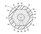
- the second metal plate 67 includes six third outer wall surfaces 73 positioned on the radially outer side with respect to the first outer wall surface 71, and 6 positioned on the same plane as the second outer wall surface 72.
- the third outer wall surface 73 corresponds to the aforementioned hexagonal corner.
- the fourth outer wall surface 74 corresponds to the aforementioned hexagonal side.
- the second outer wall surfaces 72 are provided at equal intervals in the circumferential direction.
- the second outer wall surface 72 is used as a reference when the rotary shaft 38 is press-fitted into the laminated metal plates 66 and 67 together with the fourth outer wall surface 74 on the same plane.
- the inner core 62 may have a hexagonal cross-sectional shape. Depending on the number of poles of the bond magnet 63, the cross-sectional shape of the inner core 62 can be changed as appropriate.
- the engaged portion of the inner core may be a convex portion that protrudes radially outward in a cross section parallel to the axial direction.
- the engagement portion of the bond magnet may be a recess that is recessed outward in the radial direction.
- the engaged portion of the inner core may be provided at a location corresponding to a side of the polygon when the cross section of the inter core is a polygon. In the modification, it is sufficient that two or more engaged portions of the inner core are provided.
- first outer wall surface of the first metal plate and the third outer wall surface of the second metal plate may be flat.
- second outer wall surface of the first metal plate may be a curved surface.
- the fourth outer wall surface of the second metal plate may be a curved surface located on the same curved surface as the second outer wall surface.
- the second outer wall surface of the first metal plate may not be provided at equal intervals in the circumferential direction.
- the end surface of the inner core may not be on the same plane as the end surface of the bond magnet.
- the inner core is not limited to a laminated body made of a plurality of metal plates, and may be composed of one member. The present disclosure is not limited to the embodiments described above, and can be implemented in various forms without departing from the spirit of the present disclosure.
Landscapes
- Engineering & Computer Science (AREA)
- Mechanical Engineering (AREA)
- General Engineering & Computer Science (AREA)
- Power Engineering (AREA)
- Chemical & Material Sciences (AREA)
- Combustion & Propulsion (AREA)
- Iron Core Of Rotating Electric Machines (AREA)
- Structures Of Non-Positive Displacement Pumps (AREA)
- Permanent Field Magnets Of Synchronous Machinery (AREA)
- Connection Of Motors, Electrical Generators, Mechanical Devices, And The Like (AREA)
Priority Applications (2)
| Application Number | Priority Date | Filing Date | Title |
|---|---|---|---|
| US15/738,869 US10385863B2 (en) | 2015-06-26 | 2016-06-21 | Rotor |
| DE112016002915.2T DE112016002915B4 (de) | 2015-06-26 | 2016-06-21 | Rotor |
Applications Claiming Priority (2)
| Application Number | Priority Date | Filing Date | Title |
|---|---|---|---|
| JP2015-128500 | 2015-06-26 | ||
| JP2015128500A JP6308177B2 (ja) | 2015-06-26 | 2015-06-26 | 回転子 |
Publications (1)
| Publication Number | Publication Date |
|---|---|
| WO2016208179A1 true WO2016208179A1 (ja) | 2016-12-29 |
Family
ID=57584790
Family Applications (1)
| Application Number | Title | Priority Date | Filing Date |
|---|---|---|---|
| PCT/JP2016/002966 Ceased WO2016208179A1 (ja) | 2015-06-26 | 2016-06-21 | 回転子 |
Country Status (4)
| Country | Link |
|---|---|
| US (1) | US10385863B2 (enExample) |
| JP (1) | JP6308177B2 (enExample) |
| DE (1) | DE112016002915B4 (enExample) |
| WO (1) | WO2016208179A1 (enExample) |
Families Citing this family (3)
| Publication number | Priority date | Publication date | Assignee | Title |
|---|---|---|---|---|
| US12059775B2 (en) | 2019-12-19 | 2024-08-13 | Black & Decker Inc. | Power tool with compact motor assembly |
| US11509193B2 (en) | 2019-12-19 | 2022-11-22 | Black & Decker Inc. | Power tool with compact motor assembly |
| US11705778B2 (en) | 2019-12-19 | 2023-07-18 | Black & Decker Inc. | Power tool with compact motor assembly |
Citations (4)
| Publication number | Priority date | Publication date | Assignee | Title |
|---|---|---|---|---|
| JP2002305847A (ja) * | 2001-04-02 | 2002-10-18 | Nidec Shibaura Corp | モータ |
| JP2011239546A (ja) * | 2010-05-10 | 2011-11-24 | Makita Corp | Dcブラシレスモータ |
| JP2014173456A (ja) * | 2013-03-07 | 2014-09-22 | Aisan Ind Co Ltd | 回転体 |
| WO2015045294A1 (ja) * | 2013-09-24 | 2015-04-02 | 株式会社デンソー | 燃料ポンプ |
Family Cites Families (12)
| Publication number | Priority date | Publication date | Assignee | Title |
|---|---|---|---|---|
| US4776759A (en) * | 1987-12-09 | 1988-10-11 | Jacuzzi Whirlpool Bath | Dry sun pump seal |
| JPH02103193A (ja) | 1988-10-13 | 1990-04-16 | Oki Electric Ind Co Ltd | 名刺及びそのコード情報の読み取り方法 |
| GB0130602D0 (en) * | 2001-12-21 | 2002-02-06 | Johnson Electric Sa | Brushless D.C. motor |
| JP2005295775A (ja) * | 2004-04-05 | 2005-10-20 | Nidec Shibaura Corp | モータの回転子 |
| DE102005048546A1 (de) * | 2005-10-11 | 2007-04-12 | Robert Bosch Gmbh | Rotor für eine elektrische Maschine |
| DE102006006882A1 (de) * | 2005-11-21 | 2007-05-24 | Robert Bosch Gmbh | Elektromaschine und Rotor für eine Elektromaschine |
| CN101553971B (zh) * | 2006-08-14 | 2012-07-04 | 博泽汽车部件有限公司及两合公司,乌茨堡 | 用于电动机的转子 |
| JP2010011626A (ja) | 2008-06-26 | 2010-01-14 | Jtekt Corp | 電気モータ用回転子 |
| DE102011105867B4 (de) * | 2011-06-03 | 2025-10-02 | Minebea Mitsumi Inc. | Rotor für eine elektrische Maschine |
| US9130426B2 (en) * | 2011-10-31 | 2015-09-08 | Regal Beloit America, Inc. | Permanent magnet rotors and methods of assembling the same |
| DE102012219349A1 (de) * | 2012-10-23 | 2014-04-24 | Robert Bosch Gmbh | Rotor für Elektromaschine mit Sollbruchstellen |
| JP6175993B2 (ja) * | 2013-08-30 | 2017-08-09 | 株式会社デンソー | ブラシレスモータの回転子 |
-
2015
- 2015-06-26 JP JP2015128500A patent/JP6308177B2/ja active Active
-
2016
- 2016-06-21 WO PCT/JP2016/002966 patent/WO2016208179A1/ja not_active Ceased
- 2016-06-21 DE DE112016002915.2T patent/DE112016002915B4/de active Active
- 2016-06-21 US US15/738,869 patent/US10385863B2/en active Active
Patent Citations (4)
| Publication number | Priority date | Publication date | Assignee | Title |
|---|---|---|---|---|
| JP2002305847A (ja) * | 2001-04-02 | 2002-10-18 | Nidec Shibaura Corp | モータ |
| JP2011239546A (ja) * | 2010-05-10 | 2011-11-24 | Makita Corp | Dcブラシレスモータ |
| JP2014173456A (ja) * | 2013-03-07 | 2014-09-22 | Aisan Ind Co Ltd | 回転体 |
| WO2015045294A1 (ja) * | 2013-09-24 | 2015-04-02 | 株式会社デンソー | 燃料ポンプ |
Also Published As
| Publication number | Publication date |
|---|---|
| JP2017011974A (ja) | 2017-01-12 |
| JP6308177B2 (ja) | 2018-04-11 |
| US20180195523A1 (en) | 2018-07-12 |
| DE112016002915B4 (de) | 2025-04-30 |
| US10385863B2 (en) | 2019-08-20 |
| DE112016002915T5 (de) | 2018-03-08 |
Similar Documents
| Publication | Publication Date | Title |
|---|---|---|
| JP6308177B2 (ja) | 回転子 | |
| US20220247268A1 (en) | Permanent magnet-embedded motor and pump device | |
| WO2015045294A1 (ja) | 燃料ポンプ | |
| EP3101784A1 (en) | Electric pump | |
| CN104025433B (zh) | 永磁电动机及压缩机 | |
| JP2009077497A (ja) | 電動機、それを用いた燃料ポンプ | |
| JP2007321570A (ja) | 燃料ポンプ | |
| JP6027768B2 (ja) | 多段オイルポンプ | |
| US20070014677A1 (en) | Pump | |
| JP2017011974A5 (enExample) | ||
| JP6074951B2 (ja) | 弁及び該弁を用いた流体ポンプ | |
| JP2013162676A (ja) | 電動機および圧縮機 | |
| US10020696B2 (en) | Direct current (DC) motor for fuel pump for vehicle | |
| JP2015178826A (ja) | オイルポンプ | |
| JP2013234630A (ja) | 燃料ポンプ | |
| WO2019073579A1 (ja) | 永久磁石型モータ、永久磁石型モータの製造方法および圧縮機 | |
| WO2017077948A1 (ja) | 燃料ポンプ | |
| KR20200060409A (ko) | 기어 펌프 | |
| WO2017104420A1 (ja) | 燃料ポンプ | |
| JP6361583B2 (ja) | 燃料ポンプ | |
| JP6286656B2 (ja) | トロコイドポンプ | |
| WO2016189837A1 (ja) | 燃料ポンプ | |
| JP6418059B2 (ja) | 燃料ポンプ | |
| JP2008306859A (ja) | ステータコア | |
| JP2018150840A (ja) | 燃料ポンプ |
Legal Events
| Date | Code | Title | Description |
|---|---|---|---|
| 121 | Ep: the epo has been informed by wipo that ep was designated in this application |
Ref document number: 16813951 Country of ref document: EP Kind code of ref document: A1 |
|
| WWE | Wipo information: entry into national phase |
Ref document number: 112016002915 Country of ref document: DE |
|
| 122 | Ep: pct application non-entry in european phase |
Ref document number: 16813951 Country of ref document: EP Kind code of ref document: A1 |
|
| WWG | Wipo information: grant in national office |
Ref document number: 112016002915 Country of ref document: DE |