WO2016208105A1 - バルブタイミング調整装置 - Google Patents
バルブタイミング調整装置 Download PDFInfo
- Publication number
- WO2016208105A1 WO2016208105A1 PCT/JP2016/002126 JP2016002126W WO2016208105A1 WO 2016208105 A1 WO2016208105 A1 WO 2016208105A1 JP 2016002126 W JP2016002126 W JP 2016002126W WO 2016208105 A1 WO2016208105 A1 WO 2016208105A1
- Authority
- WO
- WIPO (PCT)
- Prior art keywords
- rotator
- driven
- planetary
- drive
- bearing
- Prior art date
- Legal status (The legal status is an assumption and is not a legal conclusion. Google has not performed a legal analysis and makes no representation as to the accuracy of the status listed.)
- Ceased
Links
Images





Classifications
-
- F—MECHANICAL ENGINEERING; LIGHTING; HEATING; WEAPONS; BLASTING
- F01—MACHINES OR ENGINES IN GENERAL; ENGINE PLANTS IN GENERAL; STEAM ENGINES
- F01L—CYCLICALLY OPERATING VALVES FOR MACHINES OR ENGINES
- F01L1/00—Valve-gear or valve arrangements, e.g. lift-valve gear
- F01L1/34—Valve-gear or valve arrangements, e.g. lift-valve gear characterised by the provision of means for changing the timing of the valves without changing the duration of opening and without affecting the magnitude of the valve lift
- F01L1/344—Valve-gear or valve arrangements, e.g. lift-valve gear characterised by the provision of means for changing the timing of the valves without changing the duration of opening and without affecting the magnitude of the valve lift changing the angular relationship between crankshaft and camshaft, e.g. using helicoidal gear
- F01L1/352—Valve-gear or valve arrangements, e.g. lift-valve gear characterised by the provision of means for changing the timing of the valves without changing the duration of opening and without affecting the magnitude of the valve lift changing the angular relationship between crankshaft and camshaft, e.g. using helicoidal gear using bevel or epicyclic gear
-
- F—MECHANICAL ENGINEERING; LIGHTING; HEATING; WEAPONS; BLASTING
- F01—MACHINES OR ENGINES IN GENERAL; ENGINE PLANTS IN GENERAL; STEAM ENGINES
- F01L—CYCLICALLY OPERATING VALVES FOR MACHINES OR ENGINES
- F01L1/00—Valve-gear or valve arrangements, e.g. lift-valve gear
- F01L1/34—Valve-gear or valve arrangements, e.g. lift-valve gear characterised by the provision of means for changing the timing of the valves without changing the duration of opening and without affecting the magnitude of the valve lift
- F01L1/344—Valve-gear or valve arrangements, e.g. lift-valve gear characterised by the provision of means for changing the timing of the valves without changing the duration of opening and without affecting the magnitude of the valve lift changing the angular relationship between crankshaft and camshaft, e.g. using helicoidal gear
- F01L1/352—Valve-gear or valve arrangements, e.g. lift-valve gear characterised by the provision of means for changing the timing of the valves without changing the duration of opening and without affecting the magnitude of the valve lift changing the angular relationship between crankshaft and camshaft, e.g. using helicoidal gear using bevel or epicyclic gear
- F01L2001/3521—Harmonic drive of flexspline type
-
- F—MECHANICAL ENGINEERING; LIGHTING; HEATING; WEAPONS; BLASTING
- F01—MACHINES OR ENGINES IN GENERAL; ENGINE PLANTS IN GENERAL; STEAM ENGINES
- F01L—CYCLICALLY OPERATING VALVES FOR MACHINES OR ENGINES
- F01L2810/00—Arrangements solving specific problems in relation with valve gears
- F01L2810/02—Lubrication
-
- F—MECHANICAL ENGINEERING; LIGHTING; HEATING; WEAPONS; BLASTING
- F16—ENGINEERING ELEMENTS AND UNITS; GENERAL MEASURES FOR PRODUCING AND MAINTAINING EFFECTIVE FUNCTIONING OF MACHINES OR INSTALLATIONS; THERMAL INSULATION IN GENERAL
- F16H—GEARING
- F16H1/00—Toothed gearings for conveying rotary motion
- F16H1/28—Toothed gearings for conveying rotary motion with gears having orbital motion
- F16H1/32—Toothed gearings for conveying rotary motion with gears having orbital motion in which the central axis of the gearing lies inside the periphery of an orbital gear
- F16H2001/323—Toothed gearings for conveying rotary motion with gears having orbital motion in which the central axis of the gearing lies inside the periphery of an orbital gear comprising eccentric crankshafts driving or driven by a gearing
-
- F—MECHANICAL ENGINEERING; LIGHTING; HEATING; WEAPONS; BLASTING
- F16—ENGINEERING ELEMENTS AND UNITS; GENERAL MEASURES FOR PRODUCING AND MAINTAINING EFFECTIVE FUNCTIONING OF MACHINES OR INSTALLATIONS; THERMAL INSULATION IN GENERAL
- F16H—GEARING
- F16H1/00—Toothed gearings for conveying rotary motion
- F16H1/28—Toothed gearings for conveying rotary motion with gears having orbital motion
- F16H1/32—Toothed gearings for conveying rotary motion with gears having orbital motion in which the central axis of the gearing lies inside the periphery of an orbital gear
- F16H2001/327—Toothed gearings for conveying rotary motion with gears having orbital motion in which the central axis of the gearing lies inside the periphery of an orbital gear with the orbital gear having internal gear teeth
Definitions
- the present disclosure relates to a valve timing adjusting device that is attached to an internal combustion engine and adjusts the valve timing of a valve that opens and closes a camshaft by torque transmission from a crankshaft.
- a valve timing adjustment that adjusts the rotational phase between the drive rotator and the driven rotator by the planetary motion of the planetary rotator, comprising a drive rotator that rotates in conjunction with the crankshaft and a driven rotator that rotates in conjunction with the camshaft.
- Devices are conventionally known.
- a driven rotating body connected coaxially to a camshaft is a thrust bearing on both sides in the axial direction and a radial bearing from the inside in the radial direction.
- the planetary rotator that is eccentric from the drive rotator and the driven rotator is in a gear-linked state that meshes from the radially inner side to the eccentric side, thereby enabling adjustment of the rotational phase by planetary motion.
- the planetary carrier that radially bearings the drive rotator from the radial inner side allows the planetary rotator to perform a smooth planetary movement by the radial bearing of the planetary rotator also from the radial inner side.
- the planetary rotating body of Patent Document 1 is biased toward the eccentric side with respect to the driving rotating body and the driven rotating body by the restoring force generated by the elastic member interposed between the planetary carrier and the planetary rotating body.
- Patent Document 1 it is possible to reduce the occurrence of abnormal noise due to backlash at the meshing location of the planetary rotor with respect to the drive rotor and the driven rotor by setting the position of the meshing location.
- there is a gap in the thrust bearing portion of the drive rotor by the driven rotor so that the drive rotor moves to both sides in the axial direction and It turned out that another measure was required for the abnormal noise generated by the collision.
- An object of the present disclosure is to provide a valve timing adjusting device that increases silence by reducing the occurrence of abnormal noise.
- a valve timing adjustment device that is attached to an internal combustion engine and adjusts a valve timing of a valve that opens and closes a camshaft by torque transmission from a crankshaft, A drive rotor that rotates in conjunction with the crankshaft; A driven rotor that rotates in conjunction with a coaxially connected camshaft under thrust bearings on both sides in the axial direction and a radial bearing from the radially inner side of the drive rotor;
- the drive rotator and the driven rotator are eccentric, the drive rotator and the driven rotator are driven by planetary motion in a geared state in which the drive rotator and the driven rotator are engaged on the eccentric side from the radially inner side.
- a planetary rotor that adjusts the rotational phase between the rotors;
- a planetary carrier that causes the planetary rotor to make a planetary motion under a state in which the drive rotor is radially bearing from the radially inner side and the planetary rotor is radially bearing from the radially inner side;
- An elastic member that is interposed between the planetary rotator and the planet carrier and tilts the drive rotator relative to the driven rotator by generating a restoring force so as to bias the planetary rotator toward the eccentric side;
- the planetary rotator includes a planetary gear that meshes with the drive rotator and the driven rotator on the eccentric side, an outer ring that is held by the planetary gear, an inner ring that is radially supported by the planet carrier and receives a restoring force from the elastic member, And a single-row planetary bearing having a plurality of spherical rolling elements interposed between the outer ring and the inner ring.
- the outer ring is arranged so that a rolling contact portion that makes a contact angle with the spherical rolling element with a contact angle toward a specific side in the axial direction can be formed on the eccentric side.
- the thrust bearing location where the drive rotator is thrust-bearing by the driven rotator on the specific side and the eccentric side is located closer to the rotation center line of the driven rotator than the rolling contact location.
- the outer ring of the single-row planetary bearing in the planetary rotating body is held by the planetary gear that meshes with the drive rotating body and the driven rotating body on the eccentric side.
- the inner ring that is radially bearing by the planet carrier receives the restoring force from the elastic member toward the eccentric side.
- the outer ring in which a plurality of spherical rolling elements are interposed between the inner ring and the planetary bearing, makes the rolling contact point rolling to the spherical rolling element at a specific angle in the axial direction on the eccentric side. Arranged to be formed.
- the thrust component force of the restoring force that the spherical rolling element presses the outer ring to the specific side according to the contact angle is the thrust reaction force that presses the spherical rolling element to the non-specific side that is opposite to the specific side of the outer ring. It is generated at the rolling contact portion on the eccentric side.
- the anti-specific-side thrust reaction force is sequentially transmitted from the spherical rolling element to the inner ring and the planet carrier, thereby acting on the drive rotating body that performs radial bearing of the planet carrier.
- the drive rotator presses the driven rotator to the non-specific side so that the driven rotator is driven to the driven rotator.
- a thrust reaction force is generated that pushes the pressure toward the specific side.
- the thrust bearing location that is the point of action of the specific-side thrust reaction force is located closer to the rotation center line of the driven rotor than the rolling contact point that is the point of action of the anti-specific-side thrust reaction force.
- the driving rotating body that receives the specific side thrust reaction force and the anti-specific side thrust reaction force is inclined with respect to the driven rotating body integrally with the inner ring of the planetary bearing and the planet carrier.
- the drive rotor is inclined so as to increase the pressure on the driven rotor at the thrust bearing portion on the specific side and the eccentric side. This means that the drive rotator can maintain its contact with the driven rotator on both sides in the axial direction by its inclination.
- the situation in which the drive rotator moves to both sides in the axial direction and collides with the driven rotator can be regulated by the contact maintaining function in such an inclined form, and the generation of noise due to the collision can be reduced. . Therefore, it is possible to improve silence.
- the thrust bearing portion may be constructed by bringing a projecting portion protruding in the axial direction in one of the drive rotator and the driven rotator into contact with the other of the drive rotator and the driven rotator.
- the outermost peripheral portion of the protrusion may be positioned at a shorter distance than the rolling contact point with respect to the rotation center line of the driven rotator.
- the protrusion protruding in the axial direction on one of the driving rotating body and the driven rotating body constructs a thrust bearing portion by contacting with the other of the rotating bodies.
- the outermost peripheral portion of the protrusion is positioned at a shorter distance than the rolling contact portion with respect to the rotation center line of the driven rotor, so that the driving rotor is the outermost periphery It is possible to reliably incline using the part as a fulcrum. Therefore, it is possible to guarantee the inclination for bringing the drive rotator into contact with the driven rotator on both sides in the axial direction, thereby reducing the occurrence of abnormal noise. Therefore, it is possible to improve the certainty of the effect of improving the silence.
- FIG. 3 is a diagram illustrating a valve timing adjusting device according to an embodiment, and is a cross-sectional view taken along a line II in FIG. 2.
- FIG. 2 is a sectional view taken along line II-II in FIG.
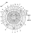
- FIG. 3 is a sectional view taken along line III-III in FIG. 1.
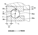
- FIG. 4 is an enlarged sectional view taken along line IV-IV in FIG. 2. It is a schematic diagram corresponding to the further enlarged view of FIG. It is a schematic diagram which shows the correlation of thrust force corresponding to FIG.
- FIG. 5 is a schematic diagram exaggeratingly illustrating a state in which the drive rotor of FIG. 4 is inclined. It is an expanded sectional view which shows the modification of FIG. It is an expanded sectional view which shows the modification of FIG.
- a valve timing adjusting device 1 is attached to a transmission system that transmits crank torque from a crankshaft (not shown) to a camshaft 2 in an internal combustion engine of a vehicle.
- the camshaft 2 opens and closes an intake valve (not shown) that is a “valve” of the internal combustion engine by transmission of crank torque. Therefore, the device 1 adjusts the valve timing of the intake valve.
- the apparatus 1 includes an actuator 4, an energization control circuit unit 7, a phase adjustment unit 8, and the like.
- the actuator 4 shown in FIG. 1 is an electric motor such as a brushless motor, for example, and has a housing body 5 and a control shaft 6.
- the housing body 5 is fixed to a fixed node of the internal combustion engine, and supports the control shaft 6 rotatably.
- the energization control circuit unit 7 includes, for example, a drive driver and its control microcomputer, and is disposed outside and / or inside the housing body 5.
- the energization control circuit unit 7 rotationally drives the control shaft 6 by controlling energization to the actuator 4 that is electrically connected.
- the phase adjustment unit 8 includes a drive rotator 10, a driven rotator 20, a planetary rotator 30, a planet carrier 50, and an elastic member 60.
- the hollow metal drive rotor 10 accommodates the other components 20, 30, 50, 60 of the phase adjustment unit 8 inside.
- the drive rotor 10 is a combination of a sun gear 11, a sprocket 13 and a sun bearing 15.
- the stepped cylindrical sun gear 11 has a drive-side internal gear portion 12 having a tip circle on the radially inner side of the root circle on the peripheral wall portion. As shown in FIG. 1, the sun gear 11 has a journal 14 formed on the peripheral wall portion on the opposite side of the camshaft 2 across the drive side internal gear portion 12 in the axial direction.
- the bottomed cylindrical sprocket 13 is screwed coaxially with the sun gear 11 from a specific side as the camshaft 2 side in the axial direction.
- the sprocket 13 is coaxially disposed on the radially outer side with respect to the cylindrical metal cam shaft 2.
- the inner peripheral surface 13 b of the bottom wall portion of the sprocket 13 is slidably fitted to the outer peripheral surface 2 a of the cam shaft 2, so that the cam shaft 2 is radially bearing from the radially inner side.
- the sprocket 13 has an annular protrusion 18 coaxially formed on the bottom wall portion that protrudes toward the opposite side of the camshaft 2 in the axial direction and continues in the circumferential direction.
- the protrusion 18 is formed in a trapezoidal cross section, thereby forming a planar tip surface 18c on the opposite side.
- the sprocket 13 is formed with a plurality of sprocket teeth 19 projecting radially outward from locations spaced at equal intervals in the circumferential direction on the outer peripheral surface of the peripheral wall portion.
- the sprocket 13 is linked to the crankshaft by passing a timing chain (not shown) between the sprocket teeth 19 and a plurality of sprocket teeth of the crankshaft. Thereby, the crank torque output from the crankshaft is transmitted to the sprocket 13 through the timing chain.
- the drive rotator 10 rotates in a certain direction (counterclockwise in FIG. 2 and clockwise in FIG. 3) in conjunction with the crankshaft under the radial bearing state by the camshaft 2.
- the annular metal solar bearing 15 is arranged coaxially on the radially inner side of the journal 14.
- the sun bearing 15 has an outer ring 15a, an inner ring 15b, and a spherical rolling element 15c.
- the sun bearing 15 is a single-row radial bearing in which a plurality of spherical rolling elements 15c are interposed between the outer ring 15a and the inner ring 15b.
- the sun bearing 15 is an open type deep groove ball bearing in the present embodiment.
- the outer ring 15 a is held from the radially outer side by the journal 14 by being press-fitted coaxially to the inner peripheral surface 14 a of the journal 14.
- the bottomed cylindrical metal driven rotor 20 is coaxially disposed on the radial inner side of the sprocket 13, thereby bearing the drive rotor 10 in a radial bearing.
- the bottom wall side outer peripheral surface 20a in the peripheral wall portion of the driven rotor 20 is slidably fitted to the bottom wall side inner peripheral surface 13a of the peripheral wall portion of the sprocket 13, thereby driving rotation.
- the body 10 is radially bearing from the inside in the radial direction.
- the driven rotor 20 is thrust-bearing between the sun gear 11 and the sprocket 13 in the axial direction, thereby thrust-bearing the drive rotor 10 on both axial sides.
- the opening end surface 20 b is in contact with the large-diameter side end surface 11 a in the peripheral wall portion of the sun gear 11 in the axial direction in the peripheral wall portion of the driven rotor 20.
- the driven rotator 20 thrust-drives the drive rotator 10 from the specific side in the axial direction.
- the outer end surface 20 c of the bottom wall portion of the driven rotor 20 is in contact with the tip end surface 18 c of the protrusion 18 on the bottom wall portion of the sprocket 13 in the axial direction.
- the driven rotator 20 thrust-drives the drive rotator 10 from the opposite side in the axial direction.
- the axial distance between the both end faces 11a and 18c in the drive rotator 10 is set larger than the axial thickness of the driven rotator 20 between the both end faces 11a and 18c by a set amount. ing.
- the drive rotator 10 can be inclined with respect to the driven rotator 20 as shown in FIG.
- the driven rotating body 20 has a connecting portion 22 that is coaxially connected to the camshaft 2 formed on the bottom wall portion.
- the driven rotator 20 is in the same direction (clockwise in FIG. 3) with respect to the drive rotator 10 in a state where the drive rotator 10 is a thrust bearing on both axial sides and a radial bearing from the radially inner side. It can rotate relatively while rotating.
- the driven rotating body 20 has a driven-side internal gear portion 24 having a tooth tip circle on the radially inner side of the root circle on the peripheral wall portion.
- the driven-side internal gear portion 24 is disposed at a location that is shifted to the specific side in the axial direction from the drive-side internal gear portion 12 and does not overlap in the radial direction.
- the inner diameter of the driven side internal gear portion 24 is set smaller than the inner diameter of the drive side internal gear portion 12.
- the number of teeth of the driven side internal gear portion 24 is set to be smaller than the number of teeth of the drive side internal gear portion 12.
- the disk-shaped metal planetary rotating body 30 as a whole is arranged eccentrically with respect to the rotating bodies 10 and 20.
- the planetary rotator 30 includes a planetary gear 31 and a planetary bearing 36.
- the stepped annular metal planetary gear 31 is disposed from the radially inner side of the driven side internal gear portion 24 to the radially inner side of the drive side internal gear portion 12.
- the planetary gear 31 is eccentric to a posture deviated in a diametrical direction with respect to the rotation center line C of the driven rotator 20.
- the planetary gear 31 has external gear portions 32 and 34 having tooth tip circles on the radially outer side of the root circle on the peripheral wall portion.
- the drive-side external gear portion 32 meshes with the drive-side internal gear portion 12 from the radially inner side on the eccentric side (hereinafter simply referred to as “eccentric side”) with respect to the rotating bodies 10 and 20.
- the driven-side external gear portion 34 is formed at a location that is shifted to the specific side in the axial direction from the drive-side external gear portion 32 and does not overlap in the radial direction.
- the outer diameter of the driven side external gear part 34 is set to be smaller than the outer diameter of the driving side external gear part 32 as a diameter different from that of the driving side external gear part 32.
- the number of teeth of the driven side external gear portion 34 is set to be smaller than the number of teeth of the drive side external gear portion 32.
- the driven-side external gear portion 34 meshes with the driven-side internal gear portion 24 from the radially inner side to the eccentric side.
- the planetary gear 31 is thrust-bearing by the driven rotor 20 from a specific side in the axial direction.
- the connection end surface 32 a connected to the driven side external gear portion 34 in the driving side external gear portion 32 of the planetary gear 31 is in contact with the opening end surface 20 b of the driven rotating body 20 in the axial direction.
- the driven rotor 20 is thrust bearing the planetary gear 31 from the specific side.
- the annular metal planetary bearing 36 is arranged from the radially inner side of the driving side external gear portion 32 to the radially inner side of the driven side external gear portion 34.
- the planetary bearing 36 is eccentric with respect to the rotation center line C of the driven rotor 20 so as to be displaced in the same radial direction as that of the planetary gear 31.
- the planetary bearing 36 has an outer ring 36a, an inner ring 36b, and a spherical rolling element 36c.
- the planetary bearing 36 is a single-row radial bearing in which a plurality of spherical rolling elements 36c are interposed between the outer ring 36a and the inner ring 36b.
- the planetary bearing 36 is an open type deep groove ball bearing.
- the outer ring 36 a is coaxially press-fitted into the inner peripheral surface 31 a of the planetary gear 31 and is held by the planetary gear 31 from the outside in the radial direction.
- the partially eccentric cylindrical metal planet carrier 50 is arranged from the radial inner side of the planetary rotating body 30 to the radial inner side of the journal 14.
- the planetary carrier 50 has a cylindrical surface-shaped input portion 51 that is coaxial with the rotating bodies 10 and 20 and the control shaft 6 on the inner peripheral surface of the peripheral wall portion.
- the input portion 51 is provided with a connection groove 52 that fits with the joint 53, and the control shaft 6 is connected to the planet carrier 50 through the joint 53. Thereby, the planet carrier 50 can rotate integrally with the control shaft 6.
- the planetary carrier 50 has a cylindrical surface coaxial portion 56 that is coaxial with the rotators 10 and 20 on the outer peripheral surface of the peripheral wall portion.
- the coaxial portion 56 is coaxially fitted into the inner ring 15b of the sun bearing 15 so that the drive rotor 10 is radially bearing from the radially inner side. Under such a bearing state, the planetary carrier 50 can rotate relative to the rotating bodies 10 and 20 while rotating coaxially.
- the planetary carrier 50 has a cylindrical surface-shaped eccentric portion 54 that is eccentric from the rotating bodies 10 and 20 on the outer peripheral surface of the peripheral wall portion on the specific side of the coaxial portion 56. .
- the eccentric portion 54 is eccentric with respect to the rotation center line C of the driven rotator 20 so as to deviate in the same radial direction as the planetary gear 31 and the planetary bearing 36.
- the eccentric portion 54 is coaxially fitted into the inner ring 36b of the planetary bearing 36, thereby radially bearing the planetary rotor 30 from the radially inner side.
- the planet carrier 50 causes at least the planetary gear 31 of the planetary rotator 30 to perform planetary motion in response to relative rotation with respect to the drive rotator 10.
- the planetary gear 31 revolves in the rotation direction of the planetary carrier 50 while rotating in its circumferential direction in a gear-linked state meshing with the rotating bodies 10 and 20 on the eccentric side.
- the metal elastic members 60 are housed one by one in the housing recesses 55 respectively opened at two locations in the circumferential direction of the eccentric portion 54.
- Each elastic member 60 is a leaf spring having a substantially U-shaped cross section.
- Each elastic member 60 is interposed between the inner ring 36 b of the planetary bearing 36 that forms the planetary rotating body 30 and the accommodation recess 55 of the accommodation destination. Accordingly, each elastic member 60 is compressed in the radial direction of the planetary rotator 30 and elastically deformed, thereby generating a restoring force.
- each elastic member 60 is disposed at a line-symmetrical position with respect to the reference line B in an arbitrary range of the axial length.
- the restoring force of each elastic member 60 is a radial force acting on the planet carrier 50 on the side opposite to the eccentric side as shown in FIG. Generate Fro.
- the restoring force of each elastic member 60 generates a radial force Fre acting on the inner ring 36b of the planetary rotating body 30 on the eccentric side as shown in FIG. 6 as a resultant force along the reference line B in FIGS.
- the planetary rotator 30 is biased by receiving the radial force Fre on the inner ring 36b in a state where the elastic members 60 are held in the housing recesses 55, so that the meshing state with the rotators 10 and 20 is achieved. Is maintained.
- phase adjustment unit 8 having the above configuration, the rotational phase between the drive rotator 10 and the driven rotator 20 is adjusted according to the rotation state of the control shaft 6.
- valve timing adjustment suitable for the operation state of the internal combustion engine is realized.
- the planetary rotator 30 rotates without planetary motion.
- the rotational phase becomes substantially unchanged, and the valve timing is held and adjusted.
- the planetary carrier 50 rotates relative to the drive rotating body 10 in the retard direction by rotating the control shaft 6 at a low speed or in the opposite direction with respect to the driving rotating body 10, at least the planetary gear of the planetary rotating body 30. Due to the planetary motion 31, the driven rotor 20 rotates relative to the drive rotor 10 in the retard direction.
- the rotational phase changes with a delay
- the valve timing is adjusted with a delay.
- the planet carrier 50 rotates relative to the drive rotator 10 in the advance direction, and at least the driven rotator 20 is caused by the planetary motion of the planetary gear 31. Rotates relative to the drive rotator 10 in the advance direction. As a result, the rotational phase is advanced and the valve timing is advanced.
- the outer ring 36 a of the planetary bearing 36 in the phase adjusting unit 8 is an outer ring having an arc-shaped cross section that is symmetrical in the axial direction by an annular groove that is recessed radially outward and continues in the circumferential direction.
- a track groove 36aa is formed.
- the inner ring 36b of the planetary bearing 36 is formed of an inner ring raceway groove 36ba having a circular arc shape that is symmetrical in the axial direction by an annular groove that is recessed radially inward and continuous in the circumferential direction.
- the outer ring raceway groove 36aa and the inner ring raceway groove 36ba are in rolling contact with the outer peripheral surface of each spherical rolling element 36c disposed between them.
- the outer ring raceway groove 36aa and the inner ring raceway groove 36ba formed at the axial center are respectively, for example, flash ground processed.
- they are displaced by a predetermined amount ⁇ t in the axial direction.
- the outer ring raceway groove 36aa and the inner ring raceway groove 36ba are displaced from each other by a predetermined amount ⁇ t in the axial direction within a range that partially overlaps in the radial direction.
- the deviation of the outer ring 36a with respect to the inner ring 36b is set on the anti-specific side, so that the deviation of the outer ring raceway groove 36aa with respect to the inner ring raceway groove 36ba is also set on the anti-specific side.
- the rolling contact point Sp where the outer ring raceway groove 36aa and each spherical rolling element 36c are in rolling contact with respect to the radial line L assumed to pass through the center point P of each spherical rolling element 36c is as follows.
- the contact angle ⁇ is sandwiched on the specific side in the axial direction. Therefore, as shown in FIG. 4 which is a longitudinal sectional view on the reference line B (see FIGS. 2 and 3), the outer ring 36a is in rolling contact with the spherical rolling element 36c in contact with the spherical rolling element 36c at a specific angle.
- the part Sp can be formed on the eccentric side.
- the planetary gear 31 has an annular plate-shaped inner flange portion 38 projecting radially inward from the driven-side outer gear portion 34 on the specific side of the rolling contact point Sp.
- the outer ring 36a is locked from the specific side in the entire circumferential direction.
- the inner ring 36b is formed by an annular plate-like outer flange 58 that protrudes radially outward from between the coaxial portion 56 and the eccentric portion 54 in the planetary carrier 50. The whole area in the circumferential direction is locked from the opposite side.
- the outer flange portion 58 is locked from the counter-specific side in the entire circumferential direction by the inner ring 15 b of the sun bearing 15. Further, on the non-specific side, the outer ring 15a of the solar bearing 15 extends in the entire region in the circumferential direction by an annular plate-shaped inner flange portion 17 projecting radially inward in the journal 14 of the drive rotating body 10. It is locked from.
- the outermost peripheral portion 18 a of the tip end surface 18 c of the protrusion 18 that constructs the thrust bearing location Se by the driven rotator 20 on the specific side is the rotation center line C of the driven rotator 20 on the eccentric side.
- it is located at a shorter distance than the rolling contact point Sp. That is, the radial distance R1 from the rotation center line C to the outermost outer peripheral portion 18a on the eccentric side is set smaller than the radial distance R2 from the same line C to the rolling contact point Sp on the eccentric side.
- the radial gap between the deepest part of the outer ring raceway groove 36aa and the spherical rolling element 36c is ⁇ R
- the radial distance from the rotation center line C to the deepest part is Ro
- the diameter of the spherical rolling element 36c is Rb.
- the radial distance R2 is derived by the following formula 1.
- the outermost peripheral portion 18a of the protrusion 18 is located farther away from the rolling contact point Sp with respect to the rotation center line C on the eccentric side.
- R2 Ro ⁇ R ⁇ Rb (1-cos ⁇ ) (Formula 1) As shown in FIGS.
- the apparatus 1 includes a lubricating structure 80 for lubricating the phase adjusting unit 8 with lubricating oil introduced from the internal combustion engine as “lubricating liquid”.
- the lubrication structure 80 includes a lubrication chamber 82, an introduction port 84, and a discharge port 86.
- the lubrication chamber 82 is formed by the internal space of the drive rotor 10.
- the meshing locations Sd and Sf of the internal gear portions 12 and 24 and the external gear portions 32 and 34, and the thrust bearings of the driving rotary body 10 and the planetary gear 31 by the driven rotary body 20 are provided.
- Locations Se, So, Sa, and rolling contact locations (including the location Sp) of the bearings 36, 15 are arranged.
- the introduction port 84 is formed radially inward of the protrusion 18 by a through hole that penetrates the connecting portion 22 and communicates with the lubrication chamber 82.
- the introduction port 84 communicates with the discharge port of the mechanical pump 9 driven by the crank torque of the crankshaft in the internal combustion engine via the introduction passage 2 b of the camshaft 2.
- the discharge port 86 is formed by a central hole that coaxially penetrates the inner flange portion 17 of the journal 14 and communicates with the lubrication chamber 82 and the outside.
- the discharge port 86 discharges to the outside the lubricating oil that has passed through the lubrication chamber 82 by lubricating each occurrence of friction.
- the innermost peripheral portion 18b of the front end surface 18c of the protrusion 18 is in the entire circumferential direction including the thrust bearing portion Se on the specific side and the eccentric side with respect to the rotation center line C of the driven rotor 20. In this case, the discharge port 86 is located farther than the inner peripheral surface 86a.
- the radial distance R3 from the rotation center line C to the innermost peripheral portion 18b is set larger in the entire area in the circumferential direction including the eccentric side than the radial distance R4 from the same line C to the inner peripheral surface 86a. Has been.
- the thrust component force Ft1 at which the spherical rolling element 36c presses the outer ring 36a toward the specific side according to the contact angle ⁇ is a radial force Fre that is a resultant force of the restoring force from each elastic member 60. Is generated at the rolling contact point Sp on the eccentric side.
- This thrust component force Ft1 is transmitted to the planetary gear 31 that locks the outer ring 36a from a specific side.
- the contact end surface 32a is continuously constructed in the circumferential direction at the contact portion with the opening end surface 20b of the driven rotor 20.
- the driven rotor 20 is capable of thrust bearing the planetary gear 31 from the specific side in the entire circumferential region including both the eccentric side and the anti-eccentric side.
- the thrust reaction force Ft2 in which the outer ring 36a presses the spherical rolling element 36c to the opposite side is generated at the eccentric rolling contact point Sp as a reaction of the thrust component force Ft1.
- the thrust reaction force Ft2 is transmitted from the spherical rolling element 36c to the inner ring 36b in the planetary bearing 36, and is also transmitted to the planet carrier 50 that locks the inner ring 36b from the opposite side. Further, in the sun bearing 15, the thrust reaction force Ft2 is transmitted from the inner ring 15b that locks the planet carrier 50 to the outer ring 15a that locks the journal 14 via the spherical rolling element 15c.
- the thrust reaction force Ft2 acting on the drive rotator 10 in this way causes a thrust force Ft3 that the drive rotator 10 presses the driven rotator 20 to the anti-specific side at the thrust bearing portion Se on the specific side and the eccentric side. Further, the thrust reaction force Ft4 that the driven rotator 20 presses the drive rotator 10 toward the specific side is generated in the thrust bearing portion Se on the specific side and the eccentric side as a reaction of the thrust force Ft3.
- the drive rotor 10 tilts with respect to the driven rotor 20 as schematically shown in FIG.
- the drive rotor 10 is inclined so as to increase the pressure on the driven rotor 20 at each of the thrust bearing portion Se on the specific side and the eccentric side and the thrust bearing portion So on the anti-specific side and the anti-eccentric side.
- the drive rotator 10 is inclined integrally with the inner ring 36 b of the planetary bearing 36 and the planet carrier 50.
- the outer ring 36 a of the single-row planetary bearing 36 is held in the planetary rotating body 30 by the planetary gear 31 that meshes with the driving rotating body 10 and the driven rotating body 20 on the eccentric side.
- the inner ring 36 b that is radially bearing by the planet carrier 50 in the planetary bearing 36 receives the resultant force of the restoring force from each elastic member 60 toward the eccentric side.
- the outer ring 36a in which a plurality of spherical rolling elements 36c are interposed between the planetary bearing 36 and the inner ring 36b is a rolling contact that makes a rolling contact with the spherical rolling element 36c at a specific angle in the axial direction.
- the locations Sp are arranged so as to be formed on the eccentric side.
- the thrust component force Ft1 of the restoring force resulting from the spherical rolling element 36c pressing the outer ring 36a toward the specific side according to the contact angle ⁇ causes the outer ring 36a to move the spherical rolling element 36c toward the non-specific side.
- the thrust reaction force Ft2 to be pressed is generated at the rolling contact point Sp on the eccentric side.
- the anti-specific-side thrust reaction force Ft2 is sequentially transmitted from the spherical rolling element 36c to the inner ring 36b and the planetary carrier 50, thereby acting on the drive rotating body 10 that performs radial bearing of the planetary carrier 50.
- the drive rotator 10 presses the driven rotator 20 to the non-specific side, thereby the driven rotator.
- a thrust reaction force Ft4 that causes the drive rotator 10 to be pressed to a specific side in 20 is generated.
- the thrust bearing portion Se that is the point of action of the specific-side thrust reaction force Ft4 with respect to the rotation center line C of the driven rotor 20 is the rolling contact that is the point of action of the anti-specific-side thrust reaction force Ft2. It will be located at a shorter distance than the place Sp.
- the drive rotor 10 that receives the specific-side thrust reaction force Ft4 and the anti-specific-side thrust reaction force Ft2 is inclined with respect to the driven rotor 20 integrally with the inner ring 36b of the planetary bearing 36 and the planet carrier 50. .
- the drive rotator 10 is inclined so as to increase the pressure on the driven rotator 20 at the thrust bearing portion Se on the specific side and the eccentric side.
- the projecting portion 18 protruding in the axial direction in the tiltable drive rotator 10 forms a thrust bearing portion Se by contacting the driven rotator 20. Accordingly, in the thrust bearing portion Se on the specific side and the eccentric side, the outermost peripheral portion 18a of the tip surface 18c of the protrusion 18 is located closer to the rotation center line C than the rolling contact portion Sp, thereby driving rotation.
- the body 10 can be surely inclined with the outermost peripheral portion 18a as a fulcrum. Therefore, it is possible to guarantee the inclination for bringing the drive rotator 10 into contact with the driven rotator 20 on both sides in the axial direction, thereby reducing the occurrence of abnormal noise. Therefore, it is possible to improve the certainty of the effect of improving the silence.
- the planetary gear 31 holding the outer ring 36a of the planetary bearing 36 is thrust-bearing from the specific side by the driven rotor 20 on both the eccentric side and the anti-eccentric side. Due to the thrust bearings on both sides, the planetary gear 31 does not easily tilt even when it is in a state of receiving the thrust component force Ft1 toward the specific side through the outer ring 36a. Therefore, as a reaction against the specific-side thrust component force Ft1, the anti-specific-side thrust reaction force Ft2 in which the outer ring 36a presses the spherical rolling element 36c can surely be generated.
- the lubricating oil that lubricates the thrust bearing portion Se is introduced into the inside of the drive rotating body 10 and thus receives a rotational centrifugal force.
- the lubricating oil is stored in the drive rotator 10 at a location farther from the discharge port 86 than the rotation center line C of the driven rotator 20. Therefore, in the thrust bearing portion Se on the specific side and the eccentric side located farther than the discharge port 86 with respect to the rotation center line C, the lubricating oil stored in the drive rotor 10 where the same portion Se is disposed is used.
- the sliding interface between the drive rotator 10 and the driven rotator 20 is lubricated.
- the inclination angle of the drive rotator 10 with respect to the driven rotator 20 is a normal angle. Can be suppressed. As a result, it is possible to continuously ensure an inclination for bringing the drive rotator 10 into contact with the driven rotator 20 on both sides in the axial direction, so that the generation of abnormal noise continues to be reduced. Therefore, it is possible to improve the reliability of the effect of increasing silence.
- the protrusion 18 that protrudes in the axial direction in the drive rotator 10 into which the lubricating oil is introduced internally forms a thrust bearing portion Se by abutment with the driven rotator 20. Accordingly, in the thrust bearing portion Se on the specific side and the eccentric side, the innermost peripheral portion 18b of the tip end surface 18c of the protrusion 18 is located far from the discharge port 86 with respect to the rotation center line C. In the stored lubricating oil, the entire sliding interface between the protrusion 18 and the driven rotor 20 is lubricated. Therefore, sliding wear at the thrust bearing location Se can be reliably suppressed.
- the apex 1018d of the tip end surface 1018c of the protrusion 18 formed in a triangular cross section is in a rolling contact position with respect to the rotation center line C of the driven rotor 20 on the eccentric side. It may be positioned at a shorter distance than Sp.
- the radial distance R5 from the rotation center line C to the eccentric vertex 1018d is set smaller than the radial distance R2 from the same line C to the eccentric rolling contact point Sp. Accordingly, the thrust bearing portion Se on the specific side and the eccentric side with respect to the rotation center line C may be positioned at a shorter distance than the rolling contact portion Sp.
- the apex of the tip surface 18 c of the protrusion 18 formed in a triangular cross section is set to the rotation center line C of the driven rotor 20 in the entire circumferential direction including the eccentric side.
- it may be located farther than the discharge port 86.
- the radial distance R5 from the rotation center line C to the apex 1018d is greater in the entire circumferential direction including the eccentric side than the radial distance R4 from the same line C to the inner peripheral surface 86a of the discharge port 86. It is set large.
- the thrust bearing portion Se on the specific side and the eccentric side with respect to the rotation center line C may be located at a farther distance than the discharge port 86.
- the thrust bearing portion Se on the specific side and the eccentric side may be positioned closer to the rotation center line C than the discharge port 86 or substantially the same distance as the discharge port 86.
- the connection end surface 32a of the planetary gear 31 may not be thrust-bearing by the driven rotor 20 on at least one of the eccentric side and the anti-eccentric side.
- the tip end surface 18 c of the protrusion 18 that protrudes from the outer end surface 20 c to the specific side in the bottom wall portion of the driven rotor 20 is the inner wall of the sprocket 13.
- the thrust bearing portion Se may be constructed by bringing it into contact with the bottom surface.
- one or three may be provided at an appropriate position between the planetary rotating body 30 and the planetary carrier 50 as long as a restoring force that urges the planetary rotating body 30 toward the eccentric side can be generated.
- the above elastic member 60 may be provided.
- At least one of the flange portions 38, 58, and 17 may not be provided. Further, as a modified example 8, the present disclosure is applied to a device that adjusts the valve timing of the exhaust valve as a “valve” and a device that adjusts the valve timing of both the intake valve and the exhaust valve as a “valve”. May be.
Landscapes
- Engineering & Computer Science (AREA)
- Mechanical Engineering (AREA)
- General Engineering & Computer Science (AREA)
- Valve Device For Special Equipments (AREA)
Abstract
Description
クランク軸と連動して回転する駆動回転体と、
駆動回転体を軸方向両側にてスラスト軸受し且つ駆動回転体を径方向内側からラジアル軸受した状態下、同軸上に連結されたカム軸と連動して回転する従動回転体と、
駆動回転体及び従動回転体とは偏心することにより、駆動回転体及び従動回転体に対して径方向内側から当該偏心側にて噛合する歯車連繋状態下、遊星運動することにより駆動回転体及び従動回転体の間の回転位相を調整する遊星回転体と、
駆動回転体を径方向内側からラジアル軸受し且つ遊星回転体を径方向内側からラジアル軸受した状態下、遊星回転体を遊星運動させる遊星キャリアと、
遊星回転体及び遊星キャリアの間に介装され、遊星回転体を偏心側へ付勢するように復原力を発生することにより、従動回転体に対して駆動回転体を傾斜させる弾性部材とを、備える。
図1,4に示すように、位相調整ユニット8において遊星ベアリング36の外輪36aは、径方向外側へと凹んで周方向に連続する円環状溝により、軸方向では対称な断面円弧形の外輪軌道溝36aaを形成している。また、遊星ベアリング36の内輪36bは、径方向内側へと凹んで周方向に連続する円環状溝により、軸方向では対称な断面円弧形の内輪軌道溝36baを形成している。外輪軌道溝36aaと内輪軌道溝36baとは、それらの間に配置される各球状転動体36cの外周面に対して、それぞれ転がり接触する。
R2=Ro-ΔR-Rb(1-cosθ) …(式1)
さて、図1,4に示すように装置1は、「潤滑液」として内燃機関から導入される潤滑油により位相調整ユニット8を潤滑するために、潤滑構造80を備えている。潤滑構造80は、潤滑室82、導入口84及び排出口86を含んで構成されている。
以下、位相調整ユニット8において発生するスラスト力の相関を、図6に基づき説明する。
装置1によると、遊星回転体30において単列式遊星ベアリング36の外輪36aは、駆動回転体10及び従動回転体20に対して偏心側での噛合をなす遊星歯車31により、保持される。ここで、遊星ベアリング36において遊星キャリア50によりラジアル軸受される内輪36bは、各弾性部材60からの復原力の合力を偏心側へと受ける。さらに、遊星ベアリング36において内輪36bとの間に複数の球状転動体36cが介装される外輪36aは、軸方向の特定側へと接触角θをなして球状転動体36cに転がり接触する転がり接触箇所Spを、偏心側にて形成可能に配置される。
一実施形態について説明したが、本開示は、当該実施形態に限定して解釈されるものではなく、要旨を逸脱しない範囲内において種々の実施形態に適用することができる。
Claims (5)
- 内燃機関に付設され、クランク軸からのトルク伝達によりカム軸(2)が開閉する動弁のバルブタイミングを調整するバルブタイミング調整装置(1)であって、
前記クランク軸と連動して回転する駆動回転体(10)と、
前記駆動回転体を軸方向両側にてスラスト軸受し且つ前記駆動回転体を径方向内側からラジアル軸受した状態下、同軸上に連結された前記カム軸と連動して回転する従動回転体(20)と、
前記駆動回転体及び前記従動回転体とは偏心することにより、前記駆動回転体及び前記従動回転体に対して径方向内側から当該偏心側にて噛合する歯車連繋状態下、遊星運動することにより前記駆動回転体及び前記従動回転体の間の回転位相を調整する遊星回転体(30)と、
前記駆動回転体を径方向内側からラジアル軸受し且つ前記遊星回転体を径方向内側からラジアル軸受した状態下、前記遊星回転体を遊星運動させる遊星キャリア(50)と、
前記遊星回転体及び前記遊星キャリアの間に介装され、前記遊星回転体を前記偏心側へ付勢するように復原力を発生することにより、前記従動回転体に対して前記駆動回転体を傾斜させる弾性部材(60)とを、備え、
前記遊星回転体は、
前記駆動回転体及び前記従動回転体に対して前記偏心側での噛合をなす遊星歯車(31)と、
前記遊星歯車により保持される外輪(36a)、前記遊星キャリアによりラジアル軸受されて前記弾性部材から前記復原力を受ける内輪(36b)、並びに前記外輪及び前記内輪の間に介装される複数の球状転動体(36c)を、有する単列式の遊星ベアリング(36)とを、含んで構成され、
前記外輪は、軸方向の特定側へ接触角(θ)をなして前記球状転動体に転がり接触する転がり接触箇所(Sp)を、前記偏心側にて形成可能に配置され、
前記駆動回転体が前記特定側且つ前記偏心側にて前記従動回転体によりスラスト軸受されるスラスト軸受箇所(Se)は、前記従動回転体の回転中心線(C)に対して前記転がり接触箇所よりも近距離に位置するバルブタイミング調整装置。 - 前記スラスト軸受箇所は、前記駆動回転体及び前記従動回転体の一方において軸方向へ突出する突部(18)を、前記駆動回転体及び前記従動回転体の他方と当接させることにより構築され、
前記偏心側にて前記突部の先端面(18c)の最外周部(18a)は、前記従動回転体の前記回転中心線に対して前記転がり接触箇所よりも近距離に位置する請求項1に記載のバルブタイミング調整装置。 - 前記遊星歯車は、前記偏心側及び反偏心側の両側にて、前記従動回転体により前記特定側からスラスト軸受される請求項1又は2に記載のバルブタイミング調整装置。
- 前記駆動回転体の内部には、前記スラスト軸受箇所が配置されると共に、前記スラスト軸受箇所を潤滑する潤滑液が導入され、
前記駆動回転体は、前記潤滑液を外部へ排出する排出口(86)を、有し、
前記特定側且つ前記偏心側の前記スラスト軸受箇所は、前記従動回転体の前記回転中心線に対して前記排出口よりも遠距離に位置する請求項1~3のいずれか一項に記載のバルブタイミング調整装置。 - 前記スラスト軸受箇所は、前記駆動回転体及び前記従動回転体の一方において軸方向へ突出する突部(18)を、前記駆動回転体及び前記従動回転体の他方と当接させることにより構築され、
周方向の全域にて前記突部の先端面(18c)の最内周部(18b)は、前記従動回転体の前記回転中心線に対して前記排出口よりも遠距離に位置する請求項4に記載のバルブタイミング調整装置。
Priority Applications (4)
| Application Number | Priority Date | Filing Date | Title |
|---|---|---|---|
| KR1020177020106A KR101896672B1 (ko) | 2015-06-23 | 2016-04-21 | 밸브 타이밍 조정장치 |
| DE112016002883.0T DE112016002883B4 (de) | 2015-06-23 | 2016-04-21 | Ventilsteuerzeitanpassungsvorrichtung |
| CN201680011882.9A CN107849952B (zh) | 2015-06-23 | 2016-04-21 | 气门正时调整装置 |
| US15/552,375 US10280816B2 (en) | 2015-06-23 | 2016-04-21 | Valve timing adjustment device |
Applications Claiming Priority (2)
| Application Number | Priority Date | Filing Date | Title |
|---|---|---|---|
| JP2015125902A JP6308176B2 (ja) | 2015-06-23 | 2015-06-23 | バルブタイミング調整装置 |
| JP2015-125902 | 2015-06-23 |
Publications (1)
| Publication Number | Publication Date |
|---|---|
| WO2016208105A1 true WO2016208105A1 (ja) | 2016-12-29 |
Family
ID=57584762
Family Applications (1)
| Application Number | Title | Priority Date | Filing Date |
|---|---|---|---|
| PCT/JP2016/002126 Ceased WO2016208105A1 (ja) | 2015-06-23 | 2016-04-21 | バルブタイミング調整装置 |
Country Status (6)
| Country | Link |
|---|---|
| US (1) | US10280816B2 (ja) |
| JP (1) | JP6308176B2 (ja) |
| KR (1) | KR101896672B1 (ja) |
| CN (1) | CN107849952B (ja) |
| DE (1) | DE112016002883B4 (ja) |
| WO (1) | WO2016208105A1 (ja) |
Cited By (1)
| Publication number | Priority date | Publication date | Assignee | Title |
|---|---|---|---|---|
| JP2022030986A (ja) * | 2020-08-07 | 2022-02-18 | 株式会社デンソー | バルブタイミング調整装置 |
Families Citing this family (13)
| Publication number | Priority date | Publication date | Assignee | Title |
|---|---|---|---|---|
| WO2019054185A1 (ja) * | 2017-09-12 | 2019-03-21 | 日立オートモティブシステムズ株式会社 | 内燃機関のバルブタイミング制御装置 |
| JP6939397B2 (ja) * | 2017-10-19 | 2021-09-22 | 株式会社デンソー | バルブタイミング調整装置 |
| US11092046B2 (en) * | 2018-03-30 | 2021-08-17 | Mitsubishi Electric Corporation | Valve timing regulation device |
| WO2019212555A1 (en) * | 2018-05-03 | 2019-11-07 | Borgwarner Inc. | Electrically actuated camshaft phaser fluid escapement channel |
| DE102018131625B4 (de) | 2018-12-10 | 2020-10-08 | Schaeffler Technologies AG & Co. KG | Planetengetriebe für eine Robotergetriebeanordnung |
| JP7056931B2 (ja) * | 2018-12-28 | 2022-04-19 | 株式会社Soken | バルブタイミング調整装置 |
| US10773794B2 (en) * | 2019-01-10 | 2020-09-15 | Bell Textron Inc. | Dynamic rotor-phasing unit |
| JP7226780B2 (ja) * | 2019-03-15 | 2023-02-21 | 株式会社Soken | バルブタイミング調整装置 |
| JP7226779B2 (ja) * | 2019-03-15 | 2023-02-21 | 株式会社Soken | バルブタイミング調整装置 |
| US11852049B2 (en) * | 2019-03-18 | 2023-12-26 | Ntn Corporation | Electric actuator |
| JP7279996B2 (ja) * | 2019-09-05 | 2023-05-23 | 株式会社Soken | バルブタイミング調整装置 |
| JP7455687B2 (ja) * | 2020-07-13 | 2024-03-26 | 住友重機械工業株式会社 | 撓み噛合い式歯車装置 |
| JP2025043441A (ja) * | 2023-09-19 | 2025-04-01 | 株式会社ミツバ | 減速機、及び、減速機付きモータ |
Citations (3)
| Publication number | Priority date | Publication date | Assignee | Title |
|---|---|---|---|---|
| JP2013096230A (ja) * | 2011-10-27 | 2013-05-20 | Denso Corp | バルブタイミング調整装置 |
| JP2015001190A (ja) * | 2013-06-14 | 2015-01-05 | 株式会社デンソー | バルブタイミング調整装置 |
| JP2015140749A (ja) * | 2014-01-29 | 2015-08-03 | 株式会社日本自動車部品総合研究所 | バルブタイミング調整装置 |
Family Cites Families (8)
| Publication number | Priority date | Publication date | Assignee | Title |
|---|---|---|---|---|
| MY120554A (en) * | 1997-10-29 | 2005-11-30 | Honda Motor Co Ltd | Valve operating system in internal combustion engine |
| JP3959713B2 (ja) * | 2002-03-22 | 2007-08-15 | 株式会社デンソー | バルブタイミング調整装置 |
| CN101178031B (zh) * | 2002-10-25 | 2010-06-02 | 株式会社电装 | 内燃机的可变气门正时控制设备 |
| JP2008095549A (ja) * | 2006-10-06 | 2008-04-24 | Denso Corp | バルブタイミング調整装置 |
| JP4360426B2 (ja) * | 2007-07-09 | 2009-11-11 | 株式会社デンソー | バルブタイミング調整装置 |
| JP5126028B2 (ja) * | 2008-11-28 | 2013-01-23 | 株式会社日本自動車部品総合研究所 | バルブタイミング調整装置 |
| JP6145716B2 (ja) | 2014-10-13 | 2017-06-14 | 株式会社Soken | バルブタイミング調整装置 |
| JP6394471B2 (ja) * | 2015-04-02 | 2018-09-26 | 株式会社Soken | バルブタイミング調整装置 |
-
2015
- 2015-06-23 JP JP2015125902A patent/JP6308176B2/ja not_active Expired - Fee Related
-
2016
- 2016-04-21 DE DE112016002883.0T patent/DE112016002883B4/de not_active Expired - Fee Related
- 2016-04-21 US US15/552,375 patent/US10280816B2/en active Active
- 2016-04-21 KR KR1020177020106A patent/KR101896672B1/ko not_active Expired - Fee Related
- 2016-04-21 CN CN201680011882.9A patent/CN107849952B/zh not_active Expired - Fee Related
- 2016-04-21 WO PCT/JP2016/002126 patent/WO2016208105A1/ja not_active Ceased
Patent Citations (3)
| Publication number | Priority date | Publication date | Assignee | Title |
|---|---|---|---|---|
| JP2013096230A (ja) * | 2011-10-27 | 2013-05-20 | Denso Corp | バルブタイミング調整装置 |
| JP2015001190A (ja) * | 2013-06-14 | 2015-01-05 | 株式会社デンソー | バルブタイミング調整装置 |
| JP2015140749A (ja) * | 2014-01-29 | 2015-08-03 | 株式会社日本自動車部品総合研究所 | バルブタイミング調整装置 |
Cited By (2)
| Publication number | Priority date | Publication date | Assignee | Title |
|---|---|---|---|---|
| JP2022030986A (ja) * | 2020-08-07 | 2022-02-18 | 株式会社デンソー | バルブタイミング調整装置 |
| JP7424245B2 (ja) | 2020-08-07 | 2024-01-30 | 株式会社デンソー | バルブタイミング調整装置 |
Also Published As
| Publication number | Publication date |
|---|---|
| US20180038246A1 (en) | 2018-02-08 |
| JP6308176B2 (ja) | 2018-04-11 |
| DE112016002883T5 (de) | 2018-03-08 |
| KR101896672B1 (ko) | 2018-09-07 |
| CN107849952A (zh) | 2018-03-27 |
| DE112016002883B4 (de) | 2022-12-08 |
| KR20170098895A (ko) | 2017-08-30 |
| JP2017008837A (ja) | 2017-01-12 |
| US10280816B2 (en) | 2019-05-07 |
| CN107849952B (zh) | 2019-11-29 |
Similar Documents
| Publication | Publication Date | Title |
|---|---|---|
| JP6308176B2 (ja) | バルブタイミング調整装置 | |
| US7624710B2 (en) | Valve timing controller | |
| JP5862696B2 (ja) | バルブタイミング調整装置 | |
| JP5888283B2 (ja) | バルブタイミング調整装置 | |
| JP2018087564A (ja) | 弁開閉時期制御装置 | |
| JP6102846B2 (ja) | バルブタイミング調整装置 | |
| JP5494547B2 (ja) | バルブタイミング調整装置 | |
| JP6394471B2 (ja) | バルブタイミング調整装置 | |
| JP4978627B2 (ja) | バルブタイミング調整装置 | |
| US11339689B2 (en) | Valve timing adjustment device | |
| US10858964B2 (en) | Valve timing adjusting device | |
| JP2016079831A (ja) | バルブタイミング調整装置 | |
| JP2009074398A (ja) | バルブタイミング調整装置 | |
| WO2020189482A1 (ja) | バルブタイミング調整装置 | |
| JP5920096B2 (ja) | バルブタイミング調整装置 | |
| JP6907822B2 (ja) | バルブタイミング調整装置、および、回転調整装置 | |
| JP6172045B2 (ja) | バルブタイミング調整装置 | |
| JP2009091996A (ja) | バルブタイミング調整装置 | |
| JP2008248804A (ja) | バルブタイミング調整装置 | |
| JP5831389B2 (ja) | バルブタイミング調整装置 | |
| JP2007071057A (ja) | バルブタイミング調整装置 |
Legal Events
| Date | Code | Title | Description |
|---|---|---|---|
| 121 | Ep: the epo has been informed by wipo that ep was designated in this application |
Ref document number: 16813882 Country of ref document: EP Kind code of ref document: A1 |
|
| ENP | Entry into the national phase |
Ref document number: 20177020106 Country of ref document: KR Kind code of ref document: A |
|
| WWE | Wipo information: entry into national phase |
Ref document number: 15552375 Country of ref document: US |
|
| WWE | Wipo information: entry into national phase |
Ref document number: 112016002883 Country of ref document: DE |
|
| 122 | Ep: pct application non-entry in european phase |
Ref document number: 16813882 Country of ref document: EP Kind code of ref document: A1 |