WO2016204237A1 - 送風機 - Google Patents
送風機 Download PDFInfo
- Publication number
- WO2016204237A1 WO2016204237A1 PCT/JP2016/067959 JP2016067959W WO2016204237A1 WO 2016204237 A1 WO2016204237 A1 WO 2016204237A1 JP 2016067959 W JP2016067959 W JP 2016067959W WO 2016204237 A1 WO2016204237 A1 WO 2016204237A1
- Authority
- WO
- WIPO (PCT)
- Prior art keywords
- impeller
- motor
- partition member
- mounting hole
- blades
- Prior art date
Links
Images


Classifications
-
- F—MECHANICAL ENGINEERING; LIGHTING; HEATING; WEAPONS; BLASTING
- F04—POSITIVE - DISPLACEMENT MACHINES FOR LIQUIDS; PUMPS FOR LIQUIDS OR ELASTIC FLUIDS
- F04D—NON-POSITIVE-DISPLACEMENT PUMPS
- F04D29/00—Details, component parts, or accessories
- F04D29/40—Casings; Connections of working fluid
- F04D29/42—Casings; Connections of working fluid for radial or helico-centrifugal pumps
- F04D29/4206—Casings; Connections of working fluid for radial or helico-centrifugal pumps especially adapted for elastic fluid pumps
- F04D29/4226—Fan casings
-
- F—MECHANICAL ENGINEERING; LIGHTING; HEATING; WEAPONS; BLASTING
- F04—POSITIVE - DISPLACEMENT MACHINES FOR LIQUIDS; PUMPS FOR LIQUIDS OR ELASTIC FLUIDS
- F04D—NON-POSITIVE-DISPLACEMENT PUMPS
- F04D25/00—Pumping installations or systems
- F04D25/02—Units comprising pumps and their driving means
- F04D25/06—Units comprising pumps and their driving means the pump being electrically driven
-
- F—MECHANICAL ENGINEERING; LIGHTING; HEATING; WEAPONS; BLASTING
- F04—POSITIVE - DISPLACEMENT MACHINES FOR LIQUIDS; PUMPS FOR LIQUIDS OR ELASTIC FLUIDS
- F04D—NON-POSITIVE-DISPLACEMENT PUMPS
- F04D29/00—Details, component parts, or accessories
- F04D29/60—Mounting; Assembling; Disassembling
- F04D29/62—Mounting; Assembling; Disassembling of radial or helico-centrifugal pumps
- F04D29/624—Mounting; Assembling; Disassembling of radial or helico-centrifugal pumps especially adapted for elastic fluid pumps
- F04D29/626—Mounting or removal of fans
-
- F—MECHANICAL ENGINEERING; LIGHTING; HEATING; WEAPONS; BLASTING
- F04—POSITIVE - DISPLACEMENT MACHINES FOR LIQUIDS; PUMPS FOR LIQUIDS OR ELASTIC FLUIDS
- F04D—NON-POSITIVE-DISPLACEMENT PUMPS
- F04D29/00—Details, component parts, or accessories
- F04D29/70—Suction grids; Strainers; Dust separation; Cleaning
- F04D29/701—Suction grids; Strainers; Dust separation; Cleaning especially adapted for elastic fluid pumps
- F04D29/706—Humidity separation
-
- F—MECHANICAL ENGINEERING; LIGHTING; HEATING; WEAPONS; BLASTING
- F05—INDEXING SCHEMES RELATING TO ENGINES OR PUMPS IN VARIOUS SUBCLASSES OF CLASSES F01-F04
- F05D—INDEXING SCHEME FOR ASPECTS RELATING TO NON-POSITIVE-DISPLACEMENT MACHINES OR ENGINES, GAS-TURBINES OR JET-PROPULSION PLANTS
- F05D2260/00—Function
- F05D2260/60—Fluid transfer
- F05D2260/602—Drainage
Definitions
- the present invention relates to a blower used in an air conditioner (for example, a vehicle air conditioner).
- an air conditioner for example, a vehicle air conditioner.
- the vehicle air conditioner cools the outside air taken in by the blower with an evaporator or heats it with a heater to cool or warm the air at an appropriate temperature for air conditioning inside the vehicle.
- the vehicle air conditioner is required to have high air blowing efficiency, small size, and low noise in order to realize comfortable comfort of the vehicle.
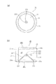
- the blower disclosed in Patent Document 1 includes an impeller (centrifugal fan) 1 that blows air sucked in the direction of the rotational drive shaft in a radially outward direction, a motor 2 that rotationally drives the impeller 1, and an impeller. 1 is provided, and a scroll casing 3 that forms a blowout flow path 4 in a spiral shape around the impeller 1 is provided.
- the impeller 1 has a bottom wall (hereinafter referred to as a cone) 1a formed in a convex cone shape toward the suction side, and a rotary drive shaft 2a of a motor 2 is connected to the top of the cone 1a.
- An internal space 5 is formed between the motor 2 and the fixed portion 2b that supports the motor 2.
- a part of the air flowing into the blowout flow path 4 flows into the internal space 5 from the gap 6 between the impeller bottom 1b side (motor side) and the fixing portion 2b supporting the motor 2 (broken arrow in FIG. 9). ft).
- the air flowing into the internal space 5 is disturbed in the vicinity of the bottom 1b side of the impeller and generates a wind noise (noise), and further flows into the internal space 5 having a larger volume than the vicinity of the gap 6, the volume changes. Due to the accompanying change in flow velocity, the air current is disturbed and wind noise is generated again.
- the blower disclosed in Patent Document 1 is provided with an annular rib 7 that slightly protrudes toward a portion that is in the vicinity of the motor side end of the impeller 1 in the blowout flow path 4. In the vicinity of 6, the airflow resistance in the radial direction is increased to prevent the inflow of air from the blowout flow path 4 to the internal space 5.
- the outside air sucked by the blower may contain moisture due to rain or the like. There is a possibility that such moisture is blown off together with the air to the blow-off flow path 4 by the impeller 1, and a part of the moisture adheres to the inner peripheral side (the peripheral surface on the motor 2 side) of the annular rib 7 and flows into the motor 2 side. is there.
- this blower is provided with a notch portion 7a in the annular rib 7 located in the vicinity of the outlet 4a of the outlet channel 4, and the moisture adhering to the inner peripheral side of the annular rib 7 is notched by the swirling component of the ventilation.
- the notch portion of the annular rib formed in the blowout flow path may disturb the ventilation in the blowout flow path and generate wind noise. Further, since the cone narrows the inner space of the impeller, it can increase the airflow resistance inside the impeller and contribute to a reduction in the blowing efficiency.
- an object of the present invention is to realize a blower that can be reduced in size while reducing noise and improving blowing efficiency, and that can drain water well without relying on an annular rib that can generate wind noise.
- a blower according to the present invention connects one end side of a plurality of blades arranged in a cylindrical shape, and protrudes toward the inside of these blades with a height lower than the height of the blades.
- An impeller having a cone formed in a shape, a housing for housing the impeller, and a motor having a rotation drive shaft connected to the center of the cone are provided.
- the housing includes an impeller mounting hole for mounting the motor therein, an intake hole for the impeller to suck in air, and a blow-out flow path for blowing out air to the air conditioner.
- the blower further includes a motor flange for mounting the motor in the impeller mounting hole, and an internal space partition member interposed between the motor flange and the impeller.
- the internal space partition member divides the internal space between the motor flange and the impeller into a motor flange side internal space and an impeller lower space.
- the edge of the internal space partition member and the edge of the impeller mounting hole of the housing By arranging the edge of the internal space partition member and the edge of the impeller mounting hole of the housing close to each other, the edge of the internal space partition member and the edge of the impeller mounting hole can be formed as a substantially continuous surface. (Claim 3). Then, the step between the edge of the internal space partitioning member and the edge of the impeller mounting hole is eliminated, the generation of wind noise can be suppressed, and the water blown off from the impeller is smoothly guided to the blowing channel, It is possible to prevent moisture from entering the lower space of the impeller.
- the height of the impeller mounting hole peripheral wall and the partition member peripheral wall is set appropriately. By setting, a substantially continuous plane can be formed by positioning the inner space partition member and the edge of the impeller mounting hole without any step.
- the blowing efficiency can be improved by setting the height of the cone to one half or less of the height of the plurality of blades (Claim 5).
- each blade rotates to form an annular surface.
- the region of the internal space partition member (partition member blade facing region) facing the annular surface may be substantially parallel to the annular surface (Claim 6).
- the internal space partition member is formed in a convex shape toward the cone in a region inside the partition member blade facing region and has a motor mounting hole in which the other end side of the motor or the rotation drive shaft is disposed. (Claim 6), the impeller lower space can be narrowed to further reduce wind noise, and moisture can be prevented from entering the impeller lower space.
- the partition member convex portion of the internal space partition member further has a water droplet trap formed on the convex surface side so as to surround the motor mounting hole continuously or discontinuously, so that moisture may invade the impeller lower space. However, it is possible to prevent moisture from reaching the motor mounting hole, that is, moisture from reaching the motor.
- the internal space partition member further includes a drain groove for draining moisture that has entered the lower space of the impeller (water droplets adhering to the impeller side of the internal space partition member), thereby further preventing moisture from reaching the motor. (Claim 8).
- One end portion of the drainage groove is positioned in the vicinity of the motor, and the other end portion is positioned farther from the motor than the one end portion, so that water can be drained more favorably.
- the motor flange may have a motor flange drain hole near the motor rather than the partition member peripheral wall (claim 10). Moisture that has entered the lower space of the impeller is drained to the outside of the blower through a drainage channel that leads from the drainage groove to the outside of the peripheral wall of the impeller mounting hole (side away from the motor). May invade space. Since the motor flange has a motor flange drain hole, even if moisture enters the internal space on the motor flange side, it can be quickly and satisfactorily drained to the outside of the blower.
- the blower according to the present invention having the above-described configuration can reduce wind noise without increasing the size of the impeller and without reducing the number of rotations. Can be realized. In addition, since the blower according to the present invention can perform good drainage without relying on the ribs in the blowout flow path, noise reduction and good drainage in the blower can be realized.
- FIG. 1 It is a figure which shows the cross-sectional schematic structure of the air blower which concerns on this invention. It is a figure which shows the planar view schematic structure (a) and cross-sectional schematic structure (b) of the impeller which the air blower shown in FIG. 1 has. It is a figure which shows the cross-sectional schematic structure of the housing of the air blower shown in FIG. It is a figure which shows the schematic perspective structure of the motor flange which the air blower shown in FIG. 1 has. It is a figure which shows the schematic perspective structure of the internal space partition member which the air blower shown in FIG. 1 has. It is a figure which shows schematic perspective structures, such as a drainage groove
- FIG. 1 It is a figure for demonstrating the installation procedure of a housing, an impeller, a motor, and a motor flange in the air blower shown in FIG. It is a cross-sectional schematic block diagram for demonstrating the airflow etc. in the air blower shown in FIG. It is a figure which shows the schematic perspective structure etc. of the conventional air blower.
- the blower 1 ⁇ / b> A includes a housing 10, an impeller 20 that is housed or mounted in the housing 10, a motor 30, a motor flange 40, and an internal space partition member 50.
- An impeller 20 that is rotationally driven by the motor 30 attached to the motor flange 40 is positioned inside the peripheral wall 101 of the housing 10, and a blow-out flow path 110 is formed between the peripheral wall 101 of the housing 10 and the impeller 20.
- an internal space partition member 50 is interposed between the motor flange 40 and the impeller 20.
- the impeller 20 has a plurality of blades 21 arranged in a cylindrical shape, and one end 21 a side (the bottom 201 side of the impeller 20) of these blades 21 is disposed inside the blade 21.
- the other end 21b of the blade 21 (on the opening 202 side of the impeller 20) is further connected by an annular connecting plate 23.
- the cone 22 has a substantially conical shape, and the bottom peripheral edge portion 221 is connected to the one end 21 a side of the blade 21.
- the top portion 222 of the cone 22 is located on the central axis of the impeller 20 and is provided with a connection hole 223 into which the rotation drive shaft 310 of the motor 30 is inserted.
- an in-impeller flow path 24 defined by the opening 202, the plurality of blades 21, and the cone 22 is formed.
- the blower 1 ⁇ / b> A reduces the ventilation resistance on the opening 202 side of the in-impeller flow path 24 by reducing the height of the cone 22 to substantially half that of the blade 21, and at the opening 202 side of the in-impeller flow path 24.
- the volume change at is substantially zero.
- the substantially conical cone 22 positioned on the bottom 201 side of the impeller 20 changes the flow direction of the air sucked from the opening 202 to the blade 21 side.
- the housing 10 that accommodates the impeller 20 in a substantially central portion has an intake hole 120 that faces the opening 202 of the impeller 20 that is accommodated, and an impeller mounting hole 130 at a portion facing the intake hole 120 (FIG. 1). .
- the intake hole 120 and the impeller mounting hole 130 are typically circular, and the impeller mounting hole 130 has a width that allows the impeller 20 to be inserted therethrough, and the impeller mounting hole peripheral wall 131 that extends in a direction away from the blowout flow path 110. have.
- the end of the impeller mounting hole peripheral wall 131 is a mounting hole peripheral wall end 131a.
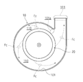
- the blow-out flow path 110 forms a substantially one-round flow path that widens from the blow-off flow path starting point portion 101 a toward the blow-out opening 111 (the more the impeller 20 and the housing 10 move toward the blow-out opening 111). The distance from the peripheral wall 101 is increased.
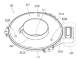
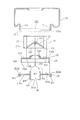
- FIG. 4 is a diagram showing a schematic perspective configuration of the motor flange 40.
- the motor flange 40 includes a flange plate portion 410 having substantially the same shape as the impeller mounting hole 130 in plan view (however, slightly larger than the impeller mounting hole 130), a motor holding portion 420 that holds the motor 30, and cooling air from the motor 30. It has a motor cooling air passage 430 that passes therethrough.
- a flange mounting groove 411 is formed on the circumferential edge of the flange plate 410 so as to be concave on the upper surface 410a side and to be convex on the lower surface 410b side of the flange plate 410 (for the flange mounting groove 411). (See also FIG. 7).
- the motor holding portion 420 having a substantially cylindrical shape is orthogonal to the flange plate portion 410 at the center portion of the flange plate portion 410.
- the motor holding portion 420 has a longer bottom surface 410b side of the flange plate portion 410, and can reduce the height of the motor 30 relative to the flange plate portion 410 when the motor 30 is attached (the height of the cone 22 is reduced).
- the motor 30 can be mounted on the lowered impeller 20).
- a holding bottom portion 421 substantially parallel to the flange plate portion 410 is formed at the lower end of the motor holding portion 420 (the end portion on the lower surface 410b side of the flange plate portion 410).
- the holding bottom portion 421 is a motor for the motor holding portion 420. 30 positions are defined.
- a substantially circular hole is formed at the center of the holding bottom 421.
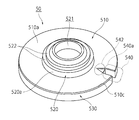
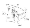
- FIG. 5 is a schematic perspective view of the internal space partition member 50.
- the internal space partition member 50 includes a partition plate portion 510 having a shape (for example, a substantially disk shape) slightly smaller than the impeller mounting hole 130, a partition member convex portion 520 that covers the motor head 302, and a partition member peripheral wall 530. ing.
- the partition member peripheral wall 530 extends from the edge portion 510c of the partition plate portion 510 (the edge portion of the internal space partition member) in a substantially ring shape in the direction opposite to the partition member convex portion 520.
- the end of the partition member peripheral wall 530 is a partition member peripheral wall end 530a (see FIG. 7).
- a substantially hemispherical partition member convex portion 520 having a diameter smaller than the diameter of the cone 22 is formed in the central portion on the upper surface 510 a side of the partition plate portion 510, and a motor mounting hole 521 is formed in the central portion of the partition member convex portion 520. Is formed.
- the partition member convex portion 520 has two water droplet traps 522 extending from the upper surface 520 a so as to be substantially parallel to the partition plate portion 510.
- the water droplet trap 522 is formed so as to continuously go around the upper surface 520a of the partition member convex portion 520, and is interposed between the upper surface 520a of the partition member convex portion 520 and the motor mounting hole 521. In the case where there are a plurality of water droplet traps 522, even if each water droplet trap 522 is formed discontinuously, any one of the water droplet traps 522 forms a partition member convex portion 520 in an arbitrary radial direction from the center of the motor mounting hole 521. As long as it is interposed between the upper surface 520a of the motor and the motor mounting hole 521.
- the partition member peripheral wall 530 has a drainage groove 540 in order to drain the water flowing through the blowout flow path 110 to the outside (FIGS. 5 and 6).
- the drainage groove 540 is formed in the inner space partition member 50 in a substantially U shape in plan view, one end portion 540a thereof is formed on the partition member convex portion 520 side, and the other end portion 540b is an edge portion 510c of the partition plate portion 510. And it forms so that a part of partition member surrounding wall 530 may be notched.
- the drainage groove 540 has a drainage groove wall part 541 having the same height as the partition member peripheral wall 530 except for the other end part 540b. Therefore, when the internal space partition member 50 is attached to the motor flange 40, the drain groove wall portion 541 of the drain groove 540 contacts the motor flange 40, and the drain groove 540 is drained with the partition plate portion 510 side and the other end portion 540b side opened. It becomes a groove.
- the drainage groove 540 may have a flange portion 542 that is recessed from the upper surface 510 a of the partition plate portion 510.
- the flange portion 542 has an isosceles triangle in plan view, the bottom portion thereof is connected to one end portion 540 a of the drainage groove 540, and the apex portion thereof is on the center side of the partition member convex portion 520. The depth is gradually increased from the partitioning member convex portion 520 side toward the drainage groove 540 side.
- FIG. 7 is a view for explaining the mounting procedure of the housing 10, the impeller 20, the motor 30, and the motor flange 40.
- the motor 30 is first mounted on the motor flange 40, then the inner space partition member 50 is mounted on the motor flange 40, and the impeller 20 is further connected to the rotation drive shaft of the motor 30.
- the impeller 20, the motor 30, the internal space partition member 50, and the motor flange 40 are mounted in the impeller mounting hole 130 of the housing 10.
- the motor 30 is mounted on the motor flange 40 by inserting the motor main body 301 of the motor 30 into the motor holder 420 and bringing the bottom surface 301a of the motor 30 into contact with the holding bottom 421 of the motor holder 420.
- the inner space partition member 50 is mounted on the motor flange 40 such that the lower surface 510b of the partition plate portion 510 of the inner space partition member 50 and the flange plate portion 410 are opposed to each other, and the motor head is formed by the partition member convex portion 520. It is performed so as to cover 302.
- the partition member convex portion 520 of the inner space partition member 50 is in close contact with the motor head 302, and the partition member peripheral wall 530 of the inner space partition member 50 is more than the flange mounting groove portion 411 of the motor flange 40. It is positioned at a position slightly closer to the motor 30 side. As shown in FIG. 1, a substantially closed motor flange side internal space 440 is formed between the motor flange 40 and the internal space partition member 50.
- the rotational drive shaft 310 of the motor 30 is inserted into the connecting hole 223 provided in the top 222 of the cone 22 of the impeller 20 (see FIG. 7).
- An impeller positioning portion (not shown) is formed on the rotary drive shaft 310.
- each blade 21 forms an annular surface 211 when rotated (see FIG. 7).
- the region of the upper surface 510a of the partition plate portion 510 of the internal space partition member 50 facing the annular surface 211 is a partition member blade facing region 511.
- the impeller 20, the motor 30, the motor flange 40, and the internal space partition member 50 are mounted in the impeller mounting hole 130 of the housing 10 by inserting the impeller 20 into the impeller mounting hole 130, and the recess of the flange mounting groove 411 of the motor flange 40.
- the mounting hole peripheral wall end 131a of the impeller mounting hole peripheral wall 131 of the housing 10 is inserted into 411a.
- the gap between the partition member peripheral wall 530 of the internal space partition member 50 and the impeller mounting hole peripheral wall 131 should be as narrow as possible.
- the blower 1A appropriately sets the length of the partition member peripheral wall 530 with respect to the impeller mounting hole peripheral wall 131, so that the edge 510c of the partition plate portion 510 of the internal space partition member 50 and the impeller mounting as shown in FIG.
- the base 131c (impeller mounting hole edge) of the hole peripheral wall 131 can be positioned without a substantial step.
- the impeller 20 When the above mounting is completed, the impeller 20 is positioned inside the housing 10 as shown in FIG. 1, and the blowout flow path 110 is formed around the impeller 20.
- the internal space partition member 50 divides the internal space of the housing 10 defined by the housing 10 and the motor flange 40 into a space on the outlet flow path 110 side and a motor flange side internal space 440.
- the space on the outlet flow path 110 side is three spaces of the outlet flow path 110, the impeller inner flow path 24, and the impeller lower space 210 formed between the internal space partition member 50 and the impeller 20. Therefore, when the diameter of the internal space partition member 50 is larger than the diameter of the impeller 20, the internal space partition member 50 is also interposed between the motor flange side internal space 440 and the blowout flow path 110.
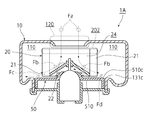
- the blower 1 ⁇ / b> A sucks outside air from the intake hole 120 by the negative pressure generated on the side of the opening 202 of the impeller 20 that is rotationally driven by the motor 30, and flows through the flow path 24 in the impeller as an air flow Fa. Further, the flow direction is changed to the blade 21 side by the cone 22, and the air flow Fb is blown out to the flow path 110.
- the height of the cone 22 is approximately one half of the blade 21. Therefore, on the opening 202 side of the flow path 24 in the impeller (region from the opening 202 of the impeller 20 to the top 222 of the cone 22), the volume change with respect to the axial direction becomes substantially zero, and the ventilation resistance is low (the blowing efficiency is reduced). In addition, the flow of the air flow Fa is hardly disturbed (noise generation is small).
- the air flow Fb flows into the blowing channel 11 in a state where the axial velocity of the impeller 20 decreases due to the low height of the cone 22, while the radial velocity increases due to the rotation of the impeller 20. It becomes the air flow Fc (FIG. 3 and FIG. 8) which flows. At this time, the moisture contained in the external air is blown off to the blowing flow path 110 together with the air flow Fc, so that the amount of moisture flowing into the impeller lower space 210 (see FIG. 1) is reduced.
- the blower 1A increases the blowing efficiency without increasing the rotation speed of the impeller 20 (that is, without increasing the wind noise or the like) and without increasing the size of the impeller 20, thereby reducing the size and the air conditioner. It contributes to noise reduction and improvement of air blowing efficiency, and can prevent moisture from reaching the motor 30.
- the impeller lower space 210 formed between the internal space partition member 50 and the impeller 20 is narrowed by the partition member convex portion 520 of the internal space partition member 50 (FIGS. 1 and 8).
- the internal space partition member 50 increases the airflow resistance of the impeller lower space 210 and reduces the air flow Fd (FIG. 8) that flows from the blow-out flow path 110 to the impeller lower space 210, thereby reducing the air flow in the impeller lower space 210. Can be prevented and noise can be reduced. Of course, it is also possible to prevent moisture from entering the impeller lower space 210.
- the impeller lower space 210 has a small volume and a high resonance frequency, even if the air flow Fd is disturbed in the impeller lower space 210, the noise increases in frequency and attenuation in the propagation path (space, etc.) increases (noise level). Decreases.)
- the blower 1 ⁇ / b> A defines an annular surface 211 formed by the ends 21 a of the rotating blades 21 by defining the distance between the end 21 a of the blade 21 of the impeller 20 and the partition plate portion 510 of the internal space partition member 50. (See FIG. 7) and the interval between the partition member blade facing region 511 (see FIG. 7) of the partition plate portion 510 of the internal space partition member 50 can be reduced.
- the blower 1A reduces the air flow Fd that flows from the blow-out flow path 110 to the impeller lower space 210, and noise due to the turbulence of the air flow in the impeller lower space 210. Can be reduced. Of course, it is also possible to prevent moisture from entering the impeller lower space 210.
- the blower 1 ⁇ / b> A can form the edge portion 510 c of the partition plate portion 510 and the area near the impeller mounting hole 130 in a substantially continuous plane. Then, the air flow Fc flowing through the edge portion 510c of the partition plate portion 510 and the region near the impeller mounting hole 130 is less disturbed by the air flow in the boundary region, and noise such as wind noise can be reduced.
- the air blower 1A narrows the gap between the partition member peripheral wall 530 and the impeller mounting hole peripheral wall 131, so that the air flow Fc flowing through the region near the boundary between the partition plate portion 510 and the impeller mounting hole 130 is the boundary region.
- the turbulence of the flow through the air is further reduced, and noise generation due to wind noise is further reduced.
- the blower 1A can smoothly flow the air flow Fc flowing through the edge portion 510c of the partition plate portion 510 and the region near the impeller mounting hole 130, and therefore the air flow Fd flowing into the impeller lower space 210 is further reduced.
- the amount of moisture that flows into the impeller lower space 210 together with the air flow Fd is further reduced.
- the air blowing efficiency can be further improved. Further improvement of the air blowing efficiency enables further downsizing and noise reduction of the air conditioner.
- the water droplet trap 522 formed on the upper surface 520a of the partition member convex portion 520 prevents water from flowing through the surface of the partition member convex portion 520 toward the motor mounting hole 521, and the water reaches the motor mounting hole 521. To prevent.
- the water droplet trap 522 increases the airflow resistance in the vicinity of the partition member convex portion 520, and therefore prevents the flow of moisture toward the motor mounting hole 521 along with the air flow Fd in the vicinity of the partition member convex portion 520.
- the blower 1 ⁇ / b> A has a drainage groove 540 for draining water flowing through the blowout channel 110, thereby realizing better drainage.
- the blower 1 ⁇ / b> A having the drainage groove 540 blows away the moisture sucked together with the outside air to the blowout flow path 110.
- Moisture flowing as water droplets through the upper surface 510 a of the partition plate portion 510 constituting the inner surface of the blow-out flow path 110 reaches the drainage groove 540.
- the drainage groove 540 causes the reached moisture to drip from the upper surface 510 a of the partition plate portion 510 to the flange plate portion 410 of the motor flange 40. If the drainage groove 540 has the flange 542, the flange 542 causes the reached water to flow into the drainage groove 540 and then dripped onto the flange plate 410.
- Moisture dripped onto the flange plate portion 410 passes through the minute drainage path (not shown) provided between the recess 411a of the flange mounting groove 411 and the mounting hole peripheral wall end 131a of the impeller mounting hole peripheral wall 131. Drained outside. If the drainage path is formed large, the air inside the blower 1A may flow and noise may be generated. Therefore, the drainage path is made minute so as not to generate noise due to the air flow of the blower 1A. Even if the drainage path is very small, the internal air pressure is higher than the outside of the blower 1A, so that moisture is pushed out of the blower 1A and can be drained well.
- the drainage groove 540 is disposed, for example, in a portion close to the outlet flow path starting point portion 101a in order to catch moisture flowing into the impeller lower space 210, and is closer to the outlet 111, for example, in order to catch moisture in the air blown to the air conditioner. It is arranged at the site.
- the drainage grooves 540 may be disposed in other parts of the blowout channel 110, or a plurality of drainage grooves 540 may be disposed.
- the flange plate portion 410 of the motor flange 40 may have a plurality or a single motor flange drain hole 410h as shown in FIG. Moisture dropped from the drain groove 540 to the flange plate portion 410 is external to the blower 1A through a minute drain path provided between the concave portion 411a of the flange mounting groove portion 411 and the mounting hole peripheral wall end portion 131a of the impeller mounting hole peripheral wall 131. However, some water may pass between the flange plate portion 410 and the partition member peripheral wall end portion 530a of the internal space partition member 50, and enter the motor flange side internal space 440.
- the flange plate 410 has the water drain hole 410h in the vicinity of the motor 30 rather than the partition member peripheral wall 530, moisture that has entered the motor flange side internal space 440 can be quickly drained to the outside of the blower 1A. it can.
- the blower according to the present invention has been described based on the embodiments.
- the present invention is not limited to the embodiments, and can be appropriately modified without departing from the spirit of the present invention.
- the structure having the drainage groove 540 in the internal space partition member 50 has been described, the drainage groove 540 may not be provided as long as moisture can be prevented from entering the blower 1A.
- blower according to the present invention can be manufactured and used industrially and can be sold commercially, the present invention has an economic value and can be used industrially. It is.
Abstract
【課題】騒音低減、送風効率向上及び小型化が可能で且つ水分を良好に排水できる送風機を実現する。 【解決手段】送風機を、ハウジング10と、円筒形状に配置されたブレード21の一端側21aを連結し且つブレード21の内側に向けブレード21の高さよりも低い凸形状に形成されたコーン22を備えてハウジング10の内側に位置づけられたインペラ20と、ブレード21の一端21a側に配設されたハウジングのインペラ装着孔130と、ブレード21の他端21b側に配設された吸気孔120と、ハウジング10とインペラ20との間に形成された吹出し流路110と、ブレード21の一端側21aに配設され且つコーン22の中心部222に回転駆動軸が連結されたモータ30と、モータ30をインペラ装着孔130に固定するためのモータフランジ40と、モータフランジ40とインペラ20との間に介在する内部空間仕切部材50とを備える構成とした。
Description
本発明は空調装置(例えば車両用空調装置)等において使用される送風機に関するものである。
車両用空調装置は、送風機で取り入れた外気等をエバポレータで冷却して、あるいはヒータで加熱して適切な温度の冷気または暖気とし車内の空調を行う。車両用空調装置は、車両の快適な居住性等を実現するため、送風効率が高く、小型化でき、騒音が少ないことが求められる。
特許文献1が開示する送風機は、図9に示すように回転駆動軸の方向に吸込んだ空気を径外方向へ送風するインペラ(遠心ファン)1と、インペラ1を回転駆動するモータ2と、インペラ1を収容し且つインペラ1の周囲に渦巻き状に吹出し流路4を形成するスクロールケーシング3を備えている。インペラ1は吸込み側に向けて凸のコーン状に形成された底壁(以下、コーンと表記する)1aを有し、コーン1aの頂部にはモータ2の回転駆動軸2aが連結され、コーン1aおよびモータ2を支える固定部2bとの間は内部空間5となっている。
このような送風機では、インペラ1の吸込み側から吸込まれた空気は、インペラ1の旋回方向(図9中の破線矢印fh)およびコーン1aの凸部に沿ったラジアル方向(図9中の破線矢印fr)の2つの通流方向成分を有して通流し、吹出し流路4へと流入する。
吹出し流路4へと流入した通気の一部は、インペラの底部1b側(モータ側)とモータ2を支える固定部2bとの隙間6から内部空間5へと流入する(図9中の破線矢印ft)。内部空間5へ流入した空気は、インペラの底部1b側近傍で気流が乱れ風切り音(騒音)を発生し、さらに隙間6の近傍よりも容積を有する内部空間5へと流入すると、容積の変化に伴う流速の変化等に起因して、気流が乱れ再び風切り音を発生する。
こうした風切り音の発生を抑制するため、特許文献1が開示する送風機は、吹出し流路4内で且つインペラ1のモータ側端近傍となる部位に向けて僅かに突出した環状リブ7を設け、隙間6の近傍において、ラジアル方向の通気抵抗を増大させて、吹出し流路4から内部空間5への空気の流入を防いでいる。
しかし送風機が吸込んだ外気は、雨などに起因する水分を含むことがある。こうした水分は空気とともにインペラ1によって吹出し流路4へと吹き飛ばされ、その一部は環状リブ7の内周側(モータ2側の周面)に付着して、モータ2側に流入する可能性がある。
そこでこの送風機は、吹出し流路4の例えば吹出し口4a近傍に位置する環状リブ7に切欠き部7aを設け、環状リブ7の内周側に付着した水分を、通気の旋回成分で切欠き部7aへと通流させ、さらに吹出し口4aに向け吹き飛ばすことで、モータ2側への水分流入を防いでいる。
しかし吹出し流路内に形成された環状リブの切欠き部は、吹出し流路内の通気を乱し、風切り音を発生し得る。またコーンは、インペラの内部空間を狭めるため、インペラ内部における通気抵抗を増大させて、送風効率低下の一因となり得る。
こうした風切り音の発生と送風効率の低下を防ぐためには、インペラを大型化し送風量を増加させたうえで回転数を少なくすればよい。しかしインペラの大型化は車両用空調装置の小型化と反する。そこで本発明は、騒音低減および送風効率向上を図りつつ、小型化が可能であり、かつ風切り音を発生し得る環状リブに拠らず水分を良好に排水できる送風機の実現を課題とした。
上記課題を解決するために、本発明に係る送風機(請求項1)は、円筒形状に配置された複数のブレードの一端側を連結し、且つこれらブレードの内側に向けブレードの高さよりも低い凸形状に形成されたコーンを備えたインペラと、インペラを収容するハウジングと、コーンの中心部に回転駆動軸が連結されたモータを備えている。そしてハウジングは、その内部にモータを装着するためのインペラ装着孔と、インペラが空気を吸気するための吸気孔と、空気を空調装置へ吹出すための吹出し流路を備えている。
さらに該送風機は、モータをインペラ装着孔に装着するためのモータフランジと、モータフランジとインペラとの間に介在する内部空間仕切部材を備えている。この内部空間仕切部材は、モータフランジとインペラとの間の内部空間をモータフランジ側内部空間とインペラ下部空間とに分割する。
インペラの直径で規定される面積よりも広い面積を有する内部空間仕切部材は、モータフランジと吹出し流路との間にも介在するから、吹出し流路とモータフランジ側内部空間とを隔てることとなる(請求項2)。
内部空間仕切部材の縁部とハウジングのインペラ装着孔縁部とを近接して配設することで、内部空間仕切部材の縁部およびインペラ装着孔縁部を略連続する面として形成することができる(請求項3)。そうすると内部空間仕切部材の縁部とインペラ装着孔縁部との段差が解消され、風切り音の発生を抑制することができるとともに、インペラから吹き飛ばされた水分を円滑に吹出し流路へと導いて、水分のインペラ下部空間への侵入を防ぐことができる。
インペラ装着孔周壁がインペラ装着孔縁部から延出していれば、そして仕切部材周壁が内部空間仕切部材の縁部から延出していれば、インペラ装着孔周壁および仕切部材周壁の高さを適切に設定することで、内部空間仕切部材とインペラ装着孔縁部とを略段差なく位置づけて略連続した平面を形成することができる(請求項4)。
コーンの高さを複数のブレードの高さの二分の一以下とすることで、送風効率を向上することができる(請求項5)。
各ブレードの一端側(インペラの一端側)は、回転して円環形状面を形成する。この円環形状面と対向する内部空間仕切部材の領域(仕切部材ブレード対向領域)を円環形状面と略平行するようにしてもよい(請求項6)。内部空間仕切部材とインペラとの間をこのように形成することで、内部空間仕切部材とインペラとの間の空間における風切り音を低減することができる。もちろん内部空間仕切部材とインペラとの間隔を狭くすれば、風切り音を更に低減できる。
また内部空間仕切部材は、仕切部材ブレード対向領域よりも内側の領域にコーンに向け凸形状に形成され且つモータの他端側または回転駆動軸が配設されるモータ装着孔を有する仕切部材凸部を備えることで(請求項6)、インペラ下部空間を狭くして風切り音を更に低減でき、また水分のインペラ下部空間への侵入を防ぐことができる。
内部空間仕切部材の仕切部材凸部は、凸面側にモータ装着孔を連続的または非連続的に囲んで凸に形成された水滴トラップを更に有することで、仮にインペラ下部空間へ水分が侵入しても、水分がモータ装着孔に到達すること、すなわち水分がモータに到達することを防ぐことができる(請求項7)。
内部空間仕切部材は、インペラ下部空間へ侵入した水分(内部空間仕切部材のインペラ側に付着した水滴)を排水するための排水溝を更に備えることで、水分のモータへの到達を更に良好に防ぐことができる(請求項8)。排水溝は、その一端部がモータの近傍に位置づけられ、他端部が一端部よりもモータから離間して位置づけられることで、水分を更に良好に排水することができる(請求項9)。
モータフランジは、仕切部材周壁よりもモータの近傍にモータフランジ水抜き孔を有してもよい(請求項10)。インペラ下部空間へ侵入した水分は、排水溝からインペラ装着孔周壁の外側(モータから離間する側)へと通じる排水経路を経て送風機の外部に排水されるが、一部の水分がモータフランジ側内部空間に侵入することがある。モータフランジがモータフランジ水抜孔を有することで、モータフランジ側内部空間に水分が侵入しても、迅速かつ良好に該送風機の外部に排水することができる。
上記構成を備えた本発明に係る送風機は、インペラを大型化せず、また回転数を少なくすることなく、風切り音を低減することができるから、送風機の騒音低減、送風効率向上および小型化を実現することができる。また本発明係る送風機は、吹出し流路内のリブに拠ることなく良好な排水が可能だから、送風機における騒音低減および良好な排水を実現することができる。
以下、本発明に係る送風機の一実施例について図面を参照して説明する。
<送風機の全体概略構成>
本発明に係る送風機1Aは、図1に示すようにハウジング10と、ハウジング10に収容または装着されるインペラ20、モータ30、モータフランジ40および内部空間仕切部材50とを有している。ハウジング10の周壁101の内部には、モータフランジ40に装着されたモータ30で回転駆動されるインペラ20が位置づけられ、ハウジング10の周壁101とインペラ20との間には吹出し流路110が形成されている。さらにモータフランジ40とインペラ20との間には、内部空間仕切部材50が介在している。
本発明に係る送風機1Aは、図1に示すようにハウジング10と、ハウジング10に収容または装着されるインペラ20、モータ30、モータフランジ40および内部空間仕切部材50とを有している。ハウジング10の周壁101の内部には、モータフランジ40に装着されたモータ30で回転駆動されるインペラ20が位置づけられ、ハウジング10の周壁101とインペラ20との間には吹出し流路110が形成されている。さらにモータフランジ40とインペラ20との間には、内部空間仕切部材50が介在している。
<インペラ>
インペラ20は、図2(a)および図2(b)に示すように複数のブレード21を円筒形状に配置し、これらブレード21の一端21a側(インペラ20の底部201側)をブレード21の内側に配置されたコーン22で連結し、さらにブレード21の他端21b(インペラ20の開口部202側)を環状の連結板23で連結したものである。コーン22は略円錐形状を有し、その底辺周縁部221はブレード21の一端21a側と連結している。コーン22の頂部222は、インペラ20の中心軸上に位置し、モータ30の回転駆動軸310が挿入される連結孔223が設けられている。
インペラ20は、図2(a)および図2(b)に示すように複数のブレード21を円筒形状に配置し、これらブレード21の一端21a側(インペラ20の底部201側)をブレード21の内側に配置されたコーン22で連結し、さらにブレード21の他端21b(インペラ20の開口部202側)を環状の連結板23で連結したものである。コーン22は略円錐形状を有し、その底辺周縁部221はブレード21の一端21a側と連結している。コーン22の頂部222は、インペラ20の中心軸上に位置し、モータ30の回転駆動軸310が挿入される連結孔223が設けられている。
上記構成を有するインペラ20の内部には、開口部202と複数のブレード21とコーン22とで規定されるインペラ内流路24が形成される。送風機1Aは、コーン22の高さをブレード21の略二分の一とすることで、インペラ内流路24の開口部202側における通気抵抗を低減するとともに、インペラ内流路24の開口部202側における容積変化を略ゼロとする。インペラ20の底部201側に位置づけられた略円錐形状のコーン22は、開口部202から吸込んだ空気の通流方向をブレード21側へと変える。
<ハウジング>
インペラ20を略中央部に収容するハウジング10は、収容したインペラ20の開口部202と対向する吸気孔120、および吸気孔120と相対する部位にインペラ装着孔130を有している(図1)。吸気孔120およびインペラ装着孔130は典型的には円形をなし、インペラ装着孔130はインペラ20を挿通できる広さを有し、吹出し流路110から離間する方向に延出したインペラ装着孔周壁131を有している。そして、インペラ装着孔周壁131の端部は装着孔周壁端部131aとなっている。
インペラ20を略中央部に収容するハウジング10は、収容したインペラ20の開口部202と対向する吸気孔120、および吸気孔120と相対する部位にインペラ装着孔130を有している(図1)。吸気孔120およびインペラ装着孔130は典型的には円形をなし、インペラ装着孔130はインペラ20を挿通できる広さを有し、吹出し流路110から離間する方向に延出したインペラ装着孔周壁131を有している。そして、インペラ装着孔周壁131の端部は装着孔周壁端部131aとなっている。
吹出し流路110は、図3に示すように吹出し流路始点部101aから吹出し口111に向け広くなる略一周の流路を成している(吹出し口111に向かうほど、インペラ20とハウジング10の周壁101との間隔は広くなる。)。
<モータフランジ>
図4はモータフランジ40の概略斜視構成を示す図である。モータフランジ40は、インペラ装着孔130と平面視略同一形状(但しインペラ装着孔130より若干大きい)を有するフランジ板部410と、モータ30を保持するモータ保持部420と、モータ30の冷却風が通過するモータ冷却風通路430を有している。
図4はモータフランジ40の概略斜視構成を示す図である。モータフランジ40は、インペラ装着孔130と平面視略同一形状(但しインペラ装着孔130より若干大きい)を有するフランジ板部410と、モータ30を保持するモータ保持部420と、モータ30の冷却風が通過するモータ冷却風通路430を有している。
フランジ板部410の円周縁部には、上面410a側において凹に形成され、フランジ板部410の下面410b側において凸に形成されたフランジ装着溝部411が形成されている(フランジ装着溝部411については図7も参照)。
図1および図7に示すように、略円筒形状を有するモータ保持部420は、フランジ板部410の中央部においてフランジ板部410と直交している。モータ保持部420は、フランジ板部410の下面410b側が長くなっており、モータ30を取付けたときにおける、フランジ板部410に対するモータ30の高さを低くすることができる(コーン22の高さを低くしたインペラ20にモータ30を装着することができる)。
モータ保持部420の下端(フランジ板部410の下面410b側の端部)には、フランジ板部410と略平行の保持底部421が形成されており、この保持底部421はモータ保持部420に対するモータ30の位置を規定する。なお保持底部421の中央部には略円形の孔が形成されている。
<内部空間仕切部材>
図5は内部空間仕切部材50の概略斜視構成を示す図である。内部空間仕切部材50は、インペラ装着孔130より僅かに小さい形状(例えば略円盤形状)を有する仕切板部510と、モータ頭部302を覆う仕切部材凸部520と、仕切部材周壁530を有している。
図5は内部空間仕切部材50の概略斜視構成を示す図である。内部空間仕切部材50は、インペラ装着孔130より僅かに小さい形状(例えば略円盤形状)を有する仕切板部510と、モータ頭部302を覆う仕切部材凸部520と、仕切部材周壁530を有している。
仕切部材周壁530は、仕切板部510の縁部510c(内部空間仕切部材の縁部)から、仕切部材凸部520と反対方向に略リング形状をなして延出している。仕切部材周壁530の端部は仕切部材周壁端部530aとなっている(図7参照)。
仕切板部510の上面510a側の中央部には、コーン22の直径より小さい直径を有する略半球形状の仕切部材凸部520が形成され、仕切部材凸部520の中央部にはモータ装着孔521が形成されている。仕切部材凸部520は、その上面520aから仕切板部510と略平行するように延出した2つの水滴トラップ522を有している。
水滴トラップ522は、仕切部材凸部520の上面520aを連続して一周するように形成されて、仕切部材凸部520の上面520aとモータ装着孔521との間に介在している。水滴トラップ522が複数の場合には、各水滴トラップ522は非連続的に形成されていても、モータ装着孔521の中心から任意の放射方向において、何れかの水滴トラップ522が仕切部材凸部520の上面520aとモータ装着孔521との間に介在していればよい。
送風機1Aでは、吹出し流路110を通流する水分を外部に排水するために、仕切部材周壁530は、排水溝540を有している(図5および図6)。排水溝540は、内部空間仕切部材50に平面視略U字形状で形成され、その一端部540aは仕切部材凸部520側に形成され、その他端部540bは、仕切板部510の縁部510cおよび仕切部材周壁530の一部を切り欠くように形成されている。
排水溝540は、他端部540bを除き、仕切部材周壁530と同一の高さの排水溝壁部541を有している。したがって、内部空間仕切部材50をモータフランジ40へ装着すると、排水溝540の排水溝壁部541はモータフランジ40に当接し、排水溝540は仕切板部510側および他端部540b側が開放した排水溝となる。
また排水溝540は仕切板部510の上面510aから凹に形成された樋部542を有していてもよい。樋部542は、図5および図6に示すように平面視二等辺三角形をなし、その底辺部は排水溝540の一端部540aと連接し、その頂点部は仕切部材凸部520の中心側に位置づけられ、その深さは仕切部材凸部520側から排水溝540側に向け徐々に深くなっている。
<ハウジングへのインペラおよびモータの装着>
図7は、ハウジング10、インペラ20、モータ30およびモータフランジ40の装着手順を説明するための図である。ハウジング10へのインペラ20およびモータ30等の装着は、先ずモータ30をモータフランジ40に装着し、次にモータフランジ40に内部空間仕切部材50を装着し、更にインペラ20をモータ30の回転駆動軸310に装着したうえで、これらインペラ20、モータ30、内部空間仕切部材50およびモータフランジ40をハウジング10のインペラ装着孔130に装着することで行われる。
図7は、ハウジング10、インペラ20、モータ30およびモータフランジ40の装着手順を説明するための図である。ハウジング10へのインペラ20およびモータ30等の装着は、先ずモータ30をモータフランジ40に装着し、次にモータフランジ40に内部空間仕切部材50を装着し、更にインペラ20をモータ30の回転駆動軸310に装着したうえで、これらインペラ20、モータ30、内部空間仕切部材50およびモータフランジ40をハウジング10のインペラ装着孔130に装着することで行われる。
モータ30のモータフランジ40への装着は、モータ30のモータ本体部301をモータ保持部420に挿入し、モータ30の底面301aをモータ保持部420の保持底部421と当接させることで行われる。
内部空間仕切部材50のモータフランジ40への装着は、内部空間仕切部材50の仕切板部510の下面510bとフランジ板部410とを相対するようにして、また仕切部材凸部520でモータ頭部302を覆うようにして行われる。
上記の装着を行うと、内部空間仕切部材50の仕切部材凸部520はモータ頭部302と略密着し、内部空間仕切部材50の仕切部材周壁530は、モータフランジ40のフランジ装着溝部411よりもモータ30側に僅かに寄った位置に位置づけられる。そして図1に示すように、モータフランジ40と内部空間仕切部材50との間には、略閉塞されたモータフランジ側内部空間440が形成される。
更にインペラ20のコーン22の頂部222に設けられた連結孔223にモータ30の回転駆動軸310を挿入する(図7参照)。回転駆動軸310には図示しないインペラ位置決め部が形成されており、このインペラ位置決め部によって、回転駆動軸310とインペラ20との位置関係が規定される結果、インペラ20の各ブレード21の一端21aと、内部空間仕切部材50の仕切板部510との間隔が規定される。
各ブレード21の一端21a側は、回転すると円環形状面211を形成する(図7参照)。この円環形状面211と対向する、内部空間仕切部材50の仕切板部510の上面510aの領域は仕切部材ブレード対向領域511となる。
インペラ20、モータ30、モータフランジ40および内部空間仕切部材50の、ハウジング10のインペラ装着孔130への装着は、インペラ20をインペラ装着孔130へ挿通し、モータフランジ40のフランジ装着溝部411の凹部411aに、ハウジング10が有するインペラ装着孔周壁131の装着孔周壁端部131aを挿入することで行われる。
ここで内部空間仕切部材50の仕切部材周壁530とインペラ装着孔周壁131との間隙はできる限り狭い方が良い。また送風機1Aは、インペラ装着孔周壁131に対し仕切部材周壁530の長さを適切に設定することで、図8に示すように内部空間仕切部材50の仕切板部510の縁部510cとインペラ装着孔周壁131の基部131c(インペラ装着孔縁部)とを略段差なく位置づけることができる。こうして仕切板部510とハウジング10のインペラ装着孔130との間に略連続した平面を形成することが好ましい。
上記の装着が完了すると、図1に示すようにインペラ20はハウジング10の内部に位置づけられ、インペラ20の周囲に吹出し流路110が形成される。このとき内部空間仕切部材50は、ハウジング10とモータフランジ40とで規定されるハウジング10の内部空間を、吹出し流路110側の空間とモータフランジ側内部空間440とに分割する。
ここで吹出し流路110側の空間は、吹出し流路110、インペラ内流路24、および内部空間仕切部材50とインペラ20との間に形成されるインペラ下部空間210の3つの空間である。したがって内部空間仕切部材50の径がインペラ20の径よりも大きい場合には、内部空間仕切部材50は、モータフランジ側内部空間440と吹出し流路と110との間にも介在する。
<インペラによる送風および騒音低減等>
図8に示すように送風機1Aは、モータ30で回転駆動されたインペラ20の開口部202側に生じる負圧によって、外気を吸気孔120から吸込んで空気流Faとしてインペラ内流路24を通流させ、さらにコーン22によって通流方向をブレード21側へと変えて空気流Fbとして流路110へ吹出す。
図8に示すように送風機1Aは、モータ30で回転駆動されたインペラ20の開口部202側に生じる負圧によって、外気を吸気孔120から吸込んで空気流Faとしてインペラ内流路24を通流させ、さらにコーン22によって通流方向をブレード21側へと変えて空気流Fbとして流路110へ吹出す。
送風機1Aは、コーン22の高さをブレード21の略二分の一としている。したがってインペラ内流路24の開口部202側(インペラ20の開口部202からコーン22の頂部222までの領域)では、軸方向に対する容積変化は略ゼロとなって、通気抵抗は低く(送風効率を高めており)また空気流Faの通流は乱れ難い(騒音発生が少ない。)。
空気流Fbは、コーン22の高さが低いためインペラ20の軸方向速度が減少する一方、インペラ20の回転によって放射方向速度が増加した状態で吹出し流路11へ流入し、吹出し流路11を通流する空気流Fc(図3および図8)となる。このとき外部の空気に含まれていた水分は、空気流Fcとともに吹出し流路110へ吹き飛ばされるため、インペラ下部空間210(図1参照)へと回り込む水分は少なくなる。
このように送風機1Aは、インペラ20の回転数を上げることなく(すなわち風切り音等を増加させることなく)、またインペラ20を大型化することなく、送風効率を高めて空調装置の小型化、低騒音化、送風効率向上に寄与するとともに、モータ30への水分到達を防ぐことができる。
<内部空間仕切部材による騒音低減等>
送風機1Aは、内部空間仕切部材50とインペラ20との間に形成されるインペラ下部空間210を、内部空間仕切部材50の仕切部材凸部520によって狭めている(図1および図8)。係る内部空間仕切部材50は、インペラ下部空間210の通気抵抗を増大させて、吹出し流路110からインペラ下部空間210へと回り込む空気流Fd(図8)を減少させ、インペラ下部空間210における空気流の乱れを防ぎ騒音を低減することができる。もちろんインペラ下部空間210への水分の回り込みも防ぐことができる。
送風機1Aは、内部空間仕切部材50とインペラ20との間に形成されるインペラ下部空間210を、内部空間仕切部材50の仕切部材凸部520によって狭めている(図1および図8)。係る内部空間仕切部材50は、インペラ下部空間210の通気抵抗を増大させて、吹出し流路110からインペラ下部空間210へと回り込む空気流Fd(図8)を減少させ、インペラ下部空間210における空気流の乱れを防ぎ騒音を低減することができる。もちろんインペラ下部空間210への水分の回り込みも防ぐことができる。
またインペラ下部空間210は容積が小さく共振周波数が高いので、仮にインペラ下部空間210で空気流Fdが乱れても、騒音は周波数が高くなって伝搬路(空間等)における減衰が増加する(騒音レベルは低下する。)。
<インペラおよび内部空間仕切部材による騒音低減等>
送風機1Aは、インペラ20のブレード21の一端21aと、内部空間仕切部材50の仕切板部510との間隔を規定することで、回転する複数のブレード21の一端21aが形成する円環形状面211(図7参照)と、内部空間仕切部材50が有する仕切板部510の仕切部材ブレード対向領域511(図7参照)との間隔を狭くすることができる。こうしてインペラ20と仕切板部510との間隔を狭めることで、送風機1Aは、吹出し流路110からインペラ下部空間210へ回り込む空気流Fdを少なくして、インペラ下部空間210における空気流の乱れによる騒音を低減することができる。もちろんインペラ下部空間210への水分の回り込みも防ぐことができる。
送風機1Aは、インペラ20のブレード21の一端21aと、内部空間仕切部材50の仕切板部510との間隔を規定することで、回転する複数のブレード21の一端21aが形成する円環形状面211(図7参照)と、内部空間仕切部材50が有する仕切板部510の仕切部材ブレード対向領域511(図7参照)との間隔を狭くすることができる。こうしてインペラ20と仕切板部510との間隔を狭めることで、送風機1Aは、吹出し流路110からインペラ下部空間210へ回り込む空気流Fdを少なくして、インペラ下部空間210における空気流の乱れによる騒音を低減することができる。もちろんインペラ下部空間210への水分の回り込みも防ぐことができる。
<内部空間仕切部材およびインペラ装着孔による騒音低減等>
送風機1Aは、図8に示すように仕切板部510の縁部510cとインペラ装着孔130近傍領域とを、略連続した平面に形成することができる。そうすると仕切板部510の縁部510cおよびインペラ装着孔130近傍領域を通流する空気流Fcは、当該境界領域における気流の乱れが少なくなって、風切り音などの騒音を低減することができる。
送風機1Aは、図8に示すように仕切板部510の縁部510cとインペラ装着孔130近傍領域とを、略連続した平面に形成することができる。そうすると仕切板部510の縁部510cおよびインペラ装着孔130近傍領域を通流する空気流Fcは、当該境界領域における気流の乱れが少なくなって、風切り音などの騒音を低減することができる。
また送風機1Aは、仕切部材周壁530とインペラ装着孔周壁131との間隙を狭くすることで、仕切板部510とインペラ装着孔130の境界の近傍領域を通流する空気流Fcは、当該境界領域における通流の乱れが更に少なくなって、風切り音などによる騒音発生は更に低減する。
こうして送風機1Aは、仕切板部510の縁部510cおよびインペラ装着孔130近傍領域を通流する空気流Fcを円滑に通流させることができ、したがってインペラ下部空間210へ回り込む空気流Fdは更に少なくなり、空気流Fdとともにインペラ下部空間210へ回り込む水分も更に少なくなる。もちろん騒音に変換されるエネルギーも少なくなるから、送風効率を更に向上できる。送風効率の更なる向上は空調装置の更なる小型化、低騒音化を可能とする。
<仕切部材凸部および水滴トラップによる浸水対策>
送風機1Aは、インペラ下部空間210へ回り込む空気流Fdを少なくするから、空気流Fdとともにインペラ下部空間210へ回り込む水分も少なくなる。仮にインペラ下部空間210へ水分が回り込んだとしても、インペラ下部空間210における通気抵抗を増加させる仕切板部510の仕切部材凸部520は、モータ装着孔521に到達する水分を減少させる。
送風機1Aは、インペラ下部空間210へ回り込む空気流Fdを少なくするから、空気流Fdとともにインペラ下部空間210へ回り込む水分も少なくなる。仮にインペラ下部空間210へ水分が回り込んだとしても、インペラ下部空間210における通気抵抗を増加させる仕切板部510の仕切部材凸部520は、モータ装着孔521に到達する水分を減少させる。
さらに仕切部材凸部520の上面520aに形成された水滴トラップ522は、仕切部材凸部520の表面を通流してモータ装着孔521へと向かう水分を阻止して、水分がモータ装着孔521に到達することを防ぐ。もちろん水滴トラップ522は、仕切部材凸部520近傍の通気抵抗を増大させるから、仕切部材凸部520近傍を空気流Fdとともにモータ装着孔521へと向かう水分の通流を防ぐ。
<排水溝による排水>
送風機1Aは、吹出し流路110を通流する水分を排水するための排水溝540を有することで更に良好な排水を実現する。
送風機1Aは、吹出し流路110を通流する水分を排水するための排水溝540を有することで更に良好な排水を実現する。
具体的には、排水溝540を有する送風機1Aは、外気とともに吸込んだ水分を吹出し流路110へ吹き飛ばす。吹出し流路110の内面を構成する仕切板部510の上面510aを水滴となって通流する水分は、排水溝540に到達する。排水溝540は、到達した水分を仕切板部510の上面510aから、モータフランジ40のフランジ板部410へと滴下させる。排水溝540が樋部542を有していれば、樋部542は、到達した水分を排水溝540へと通流させたのちフランジ板部410へと滴下させる。
フランジ板部410に滴下された水分は、フランジ装着溝部411の凹部411aとインペラ装着孔周壁131の装着孔周壁端部131aとの間に設けた微小な排水経路(図示せず)を通じて送風機1Aの外部へ排水される。排水経路を大きく形成すると送風機1Aの内部の空気が通流し、騒音が発生するおそれがある。そこで、排水経路は、送風機1Aの空気の通流による騒音の発生がない程度に微小とされている。なお、排水経路は微小であっても、送風機1Aの外部に対して内部の空気圧が高いため水分は送風機1Aの外部に押し出され、良好に排水することができる。
排水溝540は、インペラ下部空間210へ回り込む水分を捉えるため例えば吹出し流路始点部101aに近い部位に配設され、また空調装置へ送風される空気中の水分を捉えるため例えば吹出し口111に近い部位に配設される。もちろん排水溝540は、吹出し流路110の他の部位に配設されてもよく、また複数配設されてもよい。
<モータフランジ水抜き孔による排水>
モータフランジ40のフランジ板部410は、図4に示すように複数または単数のモータフランジ水抜き孔410hを有していてもよい。排水溝540からフランジ板部410に滴下された水分は、フランジ装着溝部411の凹部411aとインペラ装着孔周壁131の装着孔周壁端部131aとの間に設けた微小な排水経路を通じて送風機1Aの外部に排水されるが、一部の水分がフランジ板部410と内部空間仕切部材50の仕切部材周壁端部530aとの間を通過し、モータフランジ側内部空間440に侵入することが有り得る。しかし、フランジ板部410が仕切部材周壁530よりもモータ30の近傍に水抜き孔410hを有することで、モータフランジ側内部空間440に侵入した水分を送風機1Aの外部へと迅速に排水することができる。
モータフランジ40のフランジ板部410は、図4に示すように複数または単数のモータフランジ水抜き孔410hを有していてもよい。排水溝540からフランジ板部410に滴下された水分は、フランジ装着溝部411の凹部411aとインペラ装着孔周壁131の装着孔周壁端部131aとの間に設けた微小な排水経路を通じて送風機1Aの外部に排水されるが、一部の水分がフランジ板部410と内部空間仕切部材50の仕切部材周壁端部530aとの間を通過し、モータフランジ側内部空間440に侵入することが有り得る。しかし、フランジ板部410が仕切部材周壁530よりもモータ30の近傍に水抜き孔410hを有することで、モータフランジ側内部空間440に侵入した水分を送風機1Aの外部へと迅速に排水することができる。
以上、本発明に係る送風機を実施例に基づき説明したが、本発明は実施例に限定されるものではなく、その趣旨を逸脱することなく適宜変形して実施することができる。例えば、内部空間仕切部材50に排水溝540を有する構成で説明してきたが、送風機1Aへの水分の侵入を防止できるのであれば、排水溝540を備えない構成としてもよい。
本発明に係る送風機は、工業的に製造および使用等することができるから、また商業的に販売等することができるから、本発明は経済的価値を有して産業上利用することができる発明である。
1A 送風機
10 ハウジング
110 吹出し流路
120 吸気孔
130 インペラ装着孔
131 インペラ装着孔周壁
131c インペラ装着孔縁部(インペラ装着孔周壁の基部)
20 インペラ
21 ブレード、
21a ブレードの一端側
22 コーン
30 モータ
301a モータの底面
310 モータの回転駆動軸
40 モータフランジ
410h モータフランジ水抜き孔
50 内部空間仕切部材
510c 内部空間仕切部材の縁部(仕切板部の縁部)
511 仕切部材ブレード対向領域
520 仕切部材凸部
521 モータ装着孔
522 水滴トラップ
530 仕切部材周壁
540 排水溝
540a 排水溝の一端部
540b 排水溝の他端部
Claims (10)
- ハウジングと、
円筒形状に配置された複数のブレードと、前記複数のブレードの一端側を連結し且つ前記複数のブレードの内側に向け前記複数のブレードの高さよりも低い凸形状に形成されたコーンとを備えて前記ハウジングの内側に位置づけられたインペラと、
前記複数のブレードの一端側に配設された前記ハウジングのインペラ装着孔と、
前記複数のブレードの他端側に配設された前記ハウジングの吸気孔と、
前記ハウジングと前記インペラとの間に形成された前記ハウジングの吹出し流路と、
前記複数のブレードの一端側に配設され且つ前記コーンの中心部に回転駆動軸が連結されたモータと、
前記モータをインペラ装着孔に固定するためのモータフランジと、
前記モータフランジと、前記インペラとの間に介在する内部空間仕切部材とを備えたことを特徴とする送風機。 - 前記内部空間仕切部材は前記モータフランジと吹出し流路との間に介在することを特徴とする請求項1に記載の送風機。
- 前記内部空間仕切部材の縁部は、前記ハウジングのインペラ装着孔縁部と略連続する面を形成していることを特徴とする請求項1または2の何れかに記載の送風機。
- 前記インペラ装着孔縁部はインペラ装着孔周壁を備え、前記内部空間仕切部材の縁部は前記インペラ装着孔周壁の内側に位置づけられる仕切部材周壁を備えたことを特徴とする請求項3に記載の送風機。
- 前記コーンは、高さが前記複数のブレードの高さの二分の一以下であることを特徴とする請求項1ないし4の何れかに記載の送風機。
- 前記内部空間仕切部材は、
前記複数のブレードの一端側と対向する領域に、回転する前記複数のブレードの一端側が形成する円環形状面と略平行する仕切部材ブレード対向領域を備え、
前記仕切部材ブレード対向領域よりも内側の領域に前記コーンに向け凸形状に形成され且つ前記モータの他端側または前記回転駆動軸が配置されるモータ装着孔を有する仕切部材凸部を備えたことを特徴とする請求項1ないし5の何れかに記載の送風機。 - 請求項6に記載の送風機において、
前記内部空間仕切部材の仕切部材凸部は、凸面側に前記モータ装着孔を連続的または非連続的に囲んで凸に形成された水滴トラップを更に有することを特徴とする送風機。 - 請求項1ないし7の何れかに記載の送風機において、前記内部空間仕切部材は、前記内部空間仕切部材の前記インペラ側に付着した水滴を流入させるための排水溝を更に備えたことを特徴とする送風機。
- 前記排水溝は、一端部は前記モータの近傍に位置づけられ、他端部は前記一端部よりも前記モータから離間して位置づけられたことを特徴とする請求項8に記載の送風機。
- 前記モータフランジは、前記仕切部材周壁よりも前記モータの近傍にモータフランジ水抜き孔を有することを特徴とする請求項1ないし9の何れかに記載の送風機。
Priority Applications (3)
| Application Number | Priority Date | Filing Date | Title |
|---|---|---|---|
| CN201680028499.4A CN107614884B (zh) | 2015-06-17 | 2016-06-16 | 送风机 |
| JP2017525299A JP6719841B2 (ja) | 2015-06-17 | 2016-06-16 | 送風機 |
| EP16811711.7A EP3312431B1 (en) | 2015-06-17 | 2016-06-16 | Blower |
Applications Claiming Priority (2)
| Application Number | Priority Date | Filing Date | Title |
|---|---|---|---|
| JP2015122088 | 2015-06-17 | ||
| JP2015-122088 | 2015-06-17 |
Publications (1)
| Publication Number | Publication Date |
|---|---|
| WO2016204237A1 true WO2016204237A1 (ja) | 2016-12-22 |
Family
ID=57546147
Family Applications (1)
| Application Number | Title | Priority Date | Filing Date |
|---|---|---|---|
| PCT/JP2016/067959 WO2016204237A1 (ja) | 2015-06-17 | 2016-06-16 | 送風機 |
Country Status (4)
| Country | Link |
|---|---|
| EP (1) | EP3312431B1 (ja) |
| JP (1) | JP6719841B2 (ja) |
| CN (1) | CN107614884B (ja) |
| WO (1) | WO2016204237A1 (ja) |
Cited By (1)
| Publication number | Priority date | Publication date | Assignee | Title |
|---|---|---|---|---|
| JP2019103356A (ja) * | 2017-12-07 | 2019-06-24 | 日本電産株式会社 | モータ、及び、それを有する送風装置 |
Families Citing this family (4)
| Publication number | Priority date | Publication date | Assignee | Title |
|---|---|---|---|---|
| CN110094365B (zh) * | 2018-01-31 | 2021-09-21 | 日本电产株式会社 | 离心风扇以及具有该离心风扇的送风装置 |
| JP7199220B2 (ja) * | 2018-12-27 | 2023-01-05 | 山洋電気株式会社 | 防水ブロアファン |
| CN110005629A (zh) * | 2019-05-13 | 2019-07-12 | 杭州老板电器股份有限公司 | 风机及油烟机 |
| CN113294382A (zh) * | 2021-06-30 | 2021-08-24 | 东莞市博森精密叶轮科技有限公司 | 防水鼓风机 |
Citations (5)
| Publication number | Priority date | Publication date | Assignee | Title |
|---|---|---|---|---|
| JPH05133393A (ja) * | 1991-11-13 | 1993-05-28 | Nippondenso Co Ltd | 送風機 |
| JP2002061596A (ja) * | 2000-08-22 | 2002-02-28 | Sanyo Denki Co Ltd | 防水構造を備えた遠心ファン |
| JP2006188991A (ja) * | 2005-01-06 | 2006-07-20 | Nidec Shibaura Corp | 送風機 |
| JP2007154856A (ja) * | 2005-12-08 | 2007-06-21 | Denso Corp | 送風機の水入り防止構造 |
| JP2015052293A (ja) * | 2013-09-06 | 2015-03-19 | 株式会社デンソー | 送風機 |
Family Cites Families (3)
| Publication number | Priority date | Publication date | Assignee | Title |
|---|---|---|---|---|
| JP3843941B2 (ja) * | 2002-12-25 | 2006-11-08 | 株式会社デンソー | 遠心式送風機 |
| CN103185027B (zh) * | 2005-10-28 | 2017-12-05 | 瑞思迈发动机及马达技术股份有限公司 | 单级或多级鼓风机以及该鼓风机用嵌套式蜗壳和/或叶轮 |
| JP5223250B2 (ja) * | 2006-12-14 | 2013-06-26 | パナソニック株式会社 | 遠心羽根車および遠心送風機 |
-
2016
- 2016-06-16 JP JP2017525299A patent/JP6719841B2/ja active Active
- 2016-06-16 CN CN201680028499.4A patent/CN107614884B/zh active Active
- 2016-06-16 WO PCT/JP2016/067959 patent/WO2016204237A1/ja unknown
- 2016-06-16 EP EP16811711.7A patent/EP3312431B1/en active Active
Patent Citations (5)
| Publication number | Priority date | Publication date | Assignee | Title |
|---|---|---|---|---|
| JPH05133393A (ja) * | 1991-11-13 | 1993-05-28 | Nippondenso Co Ltd | 送風機 |
| JP2002061596A (ja) * | 2000-08-22 | 2002-02-28 | Sanyo Denki Co Ltd | 防水構造を備えた遠心ファン |
| JP2006188991A (ja) * | 2005-01-06 | 2006-07-20 | Nidec Shibaura Corp | 送風機 |
| JP2007154856A (ja) * | 2005-12-08 | 2007-06-21 | Denso Corp | 送風機の水入り防止構造 |
| JP2015052293A (ja) * | 2013-09-06 | 2015-03-19 | 株式会社デンソー | 送風機 |
Non-Patent Citations (1)
| Title |
|---|
| See also references of EP3312431A4 * |
Cited By (2)
| Publication number | Priority date | Publication date | Assignee | Title |
|---|---|---|---|---|
| JP2019103356A (ja) * | 2017-12-07 | 2019-06-24 | 日本電産株式会社 | モータ、及び、それを有する送風装置 |
| JP7043816B2 (ja) | 2017-12-07 | 2022-03-30 | 日本電産株式会社 | モータ、及び、それを有する送風装置 |
Also Published As
| Publication number | Publication date |
|---|---|
| EP3312431A1 (en) | 2018-04-25 |
| JPWO2016204237A1 (ja) | 2018-04-05 |
| EP3312431B1 (en) | 2021-05-19 |
| CN107614884B (zh) | 2020-07-28 |
| EP3312431A4 (en) | 2019-02-20 |
| CN107614884A (zh) | 2018-01-19 |
| JP6719841B2 (ja) | 2020-07-08 |
Similar Documents
| Publication | Publication Date | Title |
|---|---|---|
| WO2016204237A1 (ja) | 送風機 | |
| JP5832804B2 (ja) | 遠心式ファン | |
| US8508939B2 (en) | Fan and electronic device equipped with the same | |
| JP5809859B2 (ja) | 遠心式ファン | |
| EP2781844B1 (en) | Turbo fan and ceiling type air conditioner using the same | |
| US9335059B2 (en) | Ceiling type air conditioner | |
| US9624932B2 (en) | Centrifugal fan and air conditioner having the same | |
| JP6229141B2 (ja) | 送風装置 | |
| JP2011163235A (ja) | 遠心送風機 | |
| JP2007085352A (ja) | ファン及びそのファンフレーム | |
| WO2015125485A1 (ja) | 送風装置 | |
| WO2013021618A1 (ja) | 遠心送風機 | |
| JP2014020235A (ja) | 軸流送風機およびこれを用いた空気調和機の室内機 | |
| KR100611011B1 (ko) | 공조기의 터보팬 | |
| JP2017150327A (ja) | 送風機 | |
| JP5772370B2 (ja) | 多翼送風機 | |
| JP5076324B2 (ja) | 遠心ファン | |
| JP2011047347A (ja) | 送風ファン | |
| JP6554790B2 (ja) | ファン装置 | |
| JP2005201095A (ja) | 遠心送風機 | |
| JP2018128221A (ja) | 冷却装置 | |
| WO2019106991A1 (ja) | 排水ポンプ | |
| JP2008089262A (ja) | 送風装置および換気扇 | |
| KR100495157B1 (ko) | 터보팬 및 이를 갖춘 공기조화기 | |
| WO2018163763A1 (ja) | 送風機 |
Legal Events
| Date | Code | Title | Description |
|---|---|---|---|
| 121 | Ep: the epo has been informed by wipo that ep was designated in this application |
Ref document number: 16811711 Country of ref document: EP Kind code of ref document: A1 |
|
| ENP | Entry into the national phase |
Ref document number: 2017525299 Country of ref document: JP Kind code of ref document: A |
|
| NENP | Non-entry into the national phase |
Ref country code: DE |