WO2016203778A1 - 回転電機 - Google Patents
回転電機 Download PDFInfo
- Publication number
- WO2016203778A1 WO2016203778A1 PCT/JP2016/002961 JP2016002961W WO2016203778A1 WO 2016203778 A1 WO2016203778 A1 WO 2016203778A1 JP 2016002961 W JP2016002961 W JP 2016002961W WO 2016203778 A1 WO2016203778 A1 WO 2016203778A1
- Authority
- WO
- WIPO (PCT)
- Prior art keywords
- salient
- pole rotor
- rotating shaft
- electrical machine
- salient pole
- Prior art date
- Legal status (The legal status is an assumption and is not a legal conclusion. Google has not performed a legal analysis and makes no representation as to the accuracy of the status listed.)
- Ceased
Links
Images

Classifications
-
- H—ELECTRICITY
- H02—GENERATION; CONVERSION OR DISTRIBUTION OF ELECTRIC POWER
- H02K—DYNAMO-ELECTRIC MACHINES
- H02K1/00—Details of the magnetic circuit
- H02K1/06—Details of the magnetic circuit characterised by the shape, form or construction
- H02K1/22—Rotating parts of the magnetic circuit
- H02K1/32—Rotating parts of the magnetic circuit with channels or ducts for flow of cooling medium
- H02K1/325—Rotating parts of the magnetic circuit with channels or ducts for flow of cooling medium between salient poles
-
- H—ELECTRICITY
- H02—GENERATION; CONVERSION OR DISTRIBUTION OF ELECTRIC POWER
- H02K—DYNAMO-ELECTRIC MACHINES
- H02K19/00—Synchronous motors or generators
- H02K19/02—Synchronous motors
- H02K19/14—Synchronous motors having additional short-circuited windings for starting as asynchronous motors
-
- H—ELECTRICITY
- H02—GENERATION; CONVERSION OR DISTRIBUTION OF ELECTRIC POWER
- H02K—DYNAMO-ELECTRIC MACHINES
- H02K9/00—Arrangements for cooling or ventilating
- H02K9/02—Arrangements for cooling or ventilating by ambient air flowing through the machine
- H02K9/04—Arrangements for cooling or ventilating by ambient air flowing through the machine having means for generating a flow of cooling medium
- H02K9/06—Arrangements for cooling or ventilating by ambient air flowing through the machine having means for generating a flow of cooling medium with fans or impellers driven by the machine shaft
-
- H—ELECTRICITY
- H02—GENERATION; CONVERSION OR DISTRIBUTION OF ELECTRIC POWER
- H02K—DYNAMO-ELECTRIC MACHINES
- H02K1/00—Details of the magnetic circuit
- H02K1/06—Details of the magnetic circuit characterised by the shape, form or construction
- H02K1/22—Rotating parts of the magnetic circuit
- H02K1/24—Rotor cores with salient poles ; Variable reluctance rotors
Definitions
- Embodiments of the present invention relate to a ventilation-cooled rotating electrical machine that has a salient pole rotor and into which cooling air is sent from one end thereof.
- a rotating electric machine used as a synchronous motor or a generator has a salient pole rotor and a stator that surrounds the outer periphery of the salient pole rotor with a predetermined interval.
- the salient pole rotor has a disk-like spoke attached to the outer periphery of the central portion in the axial direction of the rotating shaft, and a cylindrical rib whose inner peripheral surface is integrally attached to the outer periphery of the spoke. .
- a plurality of salient poles are formed radially on the outer peripheral surface of the rib, and are arranged in parallel along the axial direction of the rotation shaft. A field winding is wound around each salient pole. Has been.
- a ventilation cooling method is adopted in which cooling air is sent from one end side of the salient pole rotor in the axial direction (for example, see Patent Document 1).
- the salient pole rotor and the stator surrounding the outer periphery thereof are provided in a closed frame.
- a fan for blowing air is provided on one end side of the rotating shaft of the salient pole rotor in the frame, and blows air in the radial direction as the rotating shaft rotates.
- the air blown by the fan is sent to the opposite end of the salient pole rotor through a cooler provided between the inner surface of the closed frame and the outer surface of the stator. It flows from the (one end side) along the axial direction toward the stator and salient pole rotor.
- the cooling air blown as described above cools the winding end of the stator and then flows between the stator and the salient pole rotor so that a plurality of protrusions provided on the outer peripheral surface of the rib described above are provided. It is pushed into the space between the poles. Then, after flowing through these spaces in the axial direction to cool each salient pole, the air reaches the intake side of the above-described fan for blowing air. Further, part of the air that flows between the stator and the salient pole rotor flows to the outside of the stator through the ventilation duct provided in the radial direction of the stator core, and then the air blowing described above. Reach the intake side of the fan.
- the cooling air flows from one end side of the salient pole rotor to the stator and salient pole rotor along the axial direction, so the temperature of the rotating electrical machine is from the one end side described above. It rises towards the opposite end and reaches its maximum on this opposite side. That is, in the conventional ventilation cooling system, the flow of the wind with respect to the heat generating portion of the rotating electrical machine (the salient poles of the stator and salient pole rotor) is unidirectional, so the temperature distribution is non-uniform.
- An object of the present invention is to provide a rotating electrical machine in which the temperature distribution is made uniform by improving the flow of cooling air to the heat generating portion.
- a rotating electrical machine includes a salient pole rotor and a stator that surrounds the outer periphery of the salient pole rotor with a predetermined interval, and the axial direction of the salient pole rotor
- An air cooling type rotating electrical machine in which cooling air is fed from one end side, the salient pole rotor includes a rotating shaft, a disk-like spoke integrally attached to an outer periphery of the rotating shaft, and Cylindrical ribs whose inner peripheral surfaces are integrally attached to the outer periphery of the spokes, and radially formed on the outer peripheral surfaces of the ribs, respectively, formed along the axial direction of the rotating shaft.
- a rotating electrical machine 10 used as a synchronous motor or a generator has a salient pole rotor 11 and a stator 12 that surrounds the outer periphery of the rotating electrical machine 10 with a predetermined interval.
- the salient pole rotor 11 and the stator 12 surrounding the outer periphery thereof are provided in a closed frame 13.
- a blower fan 16 is provided on one end side of the rotary shaft 15 of the salient pole rotor 11 in the frame 13, and blows air in the radial direction as the rotary shaft 15 rotates.
- a cooler 18 is provided between the inner surface of the closed frame 13 and the air guide plate 17 provided on the outer surface side of the stator 12.
- the air blown by the fan 16 is guided to the inner surface of the frame 13 and the outer surface (upper surface in the drawing) of the air guide plate 17 and sent to the cooler 18, and is cooled when passing through the cooler 18 to the left in the drawing. And sent to the opposite end (left end side in the figure) of the salient pole rotor 11.
- the air then flows from the opposite end (one end side) toward the stator 12 and the salient pole rotor 11 to the right in the figure.
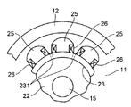
- the salient pole rotor 11 has a disc-like spoke 22 attached integrally to the outer periphery of the rotary shaft 15 by the boss 21 and an inner peripheral surface integrally attached to the outer periphery of the spoke 22. It has a cylindrical rib 23. As shown in FIG. 2, a plurality of salient poles 25 are formed radially on the outer peripheral surface of the rib 23, and are arranged along the axial direction of the rotary shaft 15 as shown in FIG. Yes. A field winding 26 is wound around each of the salient poles 25.
- the disk-shaped spokes constituting the salient pole-shaped rotor 11 are the right side of the salient pole-shaped rotor 11 on the opposite side of the cooling air feeding side, that is, the cooling air counter-feeding side. It is biased at the end. Therefore, a space 27 for blowing air is generated across the entire axial direction of the rib 23 between the outer periphery of the rotating shaft 15 and the inner periphery of the cylindrical rib 23.
- the cylindrical rib 23 is provided with a plurality of through holes 231 extending from the space 27 formed inside thereof to the plurality of salient poles 25 over almost the entire circumferential surface of the rib 23.
- the salient pole rotor 11 rotates integrally around the rotation shaft 15. Along with this rotation, the air in the frame 13 is blown in the radial direction by the fan 16. The air blown in the radial direction is guided to the cooler 18 by the inner surface of the frame 13 and the air guide plate 17. And when passing this cooler 18 to the left of the figure, it cools and becomes cooling air.
- the cooler 18 has a large number of cooling pipes (not shown), and a refrigerant (liquid or gas) is supplied from the outside into these cooling pipes, and these are exchanged by heat exchange with the air in the frame 13. Cooling.
- the low-temperature air that has passed through the cooler 18 is sent as cooling air from the left side of the frame 13 toward the salient pole rotor 11 and the stator 12 in the right direction in the figure.
- the cooling air cools the winding end 121 of the stator 12, flows between the stator 12 and the salient pole rotor 11, and further flows into the space 27 in the cylindrical rib 23.
- a part of the cooling air flowing between the stator 12 and the salient pole rotor 11 is fixed through a ventilation duct (not shown) formed in the radial direction of the iron core of the stator 12 as in the prior art. While cooling the child 12, it flows to the outside, flows on the inner surface (lower surface in the figure) of the air guide plate 17 to the right side in the figure, and reaches the intake side (left side in the figure) of the fan 16. Further, the remainder of the cooling air flowing between the stator 12 and the salient pole rotor 11 flows along the axial direction between the plurality of salient poles 25 formed radially on the outer periphery of the rib 23. After the salient pole 25 is cooled, it reaches the intake side of the fan 16.
- the cooling air that has flowed into the cylindrical rib 23 passes through the through-hole 231 provided on the peripheral surface of the rib 23 because the downstream end (right end in the drawing) is blocked by the disc-shaped spoke 22. , And flows between the plurality of salient poles 25 described above. That is, since the cooling air is supplied between the plurality of salient poles 25 through these through holes 231 and sufficient cooling air is supplied to the downstream side (right side in the drawing) in the axial direction, the salient pole rotor 11 can be cooled almost uniformly.
- the amount of air supplied to the stator 12 through the through-hole 231 and the salient pole rotor 11 is also added, the amount of air flow to a not-shown ventilation duct provided in the radial direction is also increased. It increases, and almost uniform cooling is possible as a whole.
- the disk-like spoke 22 is provided with a vent hole 221 penetrating the front and back.
- the right end of the cylindrical rib 23 shown in the figure is closed with a disk-shaped spoke 22, and the cooling air flowing into the cylindrical rib 23 is formed in a through hole 231 provided on the peripheral surface of the rib 23.
- the overall ventilation resistance may be too large. If the airflow resistance becomes too large in this way, the overall airflow volume is reduced. Therefore, a ventilation hole 221 that penetrates the disk-like spoke 22 is provided so that the airflow resistance does not become excessively large. adjust.
- vent hole 221 By providing the vent hole 221 in this way, by adjusting the vent area, a sufficient amount of ventilation can be obtained as a whole, and it is sufficient between the plurality of salient poles 25 through the through hole 231. It is possible to adjust the ventilation resistance so that a large amount of air can be supplied.
- a discharge resistor 31 may be attached (wrapped) to the outer peripheral portion (inside the space 27) of the rotating shaft 15 facing the inner peripheral surface of the cylindrical rib 23. That is, when the rotary electric machine 10 is a synchronous motor, a discharge resistor 31 that short-circuits the field winding 26 is used to obtain a starting torque at the time of starting. Since the discharge resistor 31 generates heat when energized, it is installed in a space 27 in the cylindrical rib 23 through which cooling air is concentrated.
- the discharge resistor 31 that has generated heat due to energization can be effectively cooled.
- fins 32 may be integrally provided on the outer periphery of the above-described discharge resistor 31 along the axial direction of the rotating shaft 15. The fin 32 rotates together with the rotating shaft 15 and generates blown air in the radial direction.
- the heat of the discharge resistor 31 can be radiated more effectively, and air blown in the radial direction is generated, so that the air in the space 27 is directed toward the through holes 231 provided in the ribs 23. It is possible to blow air more efficiently.
Landscapes
- Engineering & Computer Science (AREA)
- Power Engineering (AREA)
- Motor Or Generator Cooling System (AREA)
- Iron Core Of Rotating Electric Machines (AREA)
Abstract
発熱部に対する冷却気の流れを改善することにより温度分布の均一化を図った回転電機を提供する。 突極形回転子11、及び固定子12を有し、突極形回転子11は、回転軸15と、円板状のスポーク22、及び円筒状のリブ23と、リブ23の外周面に放射状に配置されそれぞれ回転軸15の軸方向に沿って形成された複数個の突極25とを有し、円板状のスポーク22を、突極形回転子11の、冷却気の反送り込み側端部に設け、かつ円筒状のリブ23にはその内側の空間から複数個の突極25間に通じる貫通孔231を設けた。
Description
本発明の実施形態は、突極形回転子を有し、その片端側から冷却気が送り込まれる通風冷却式の回転電機に関する。
同期電動機または発電機として用いられる回転電機は、突極形回転子、及びこの突極形回転子の外周を所定の間隔を保って囲む固定子を有している。突極形回転子は、その回転軸の軸方向中央部の外周に取り付けられた円板状のスポーク、及びこのスポークの外周に内周面が一体的に取り付けられている円筒状のリブを有する。このリブの外周面には、複数個の突極が放射状に形成され、それぞれ回転軸の軸方向に沿って平行に配置されており、これら各突極の周囲には界磁巻線が巻回されている。
このような回転電機の冷却方式の一つとして、突極形回転子の軸方向片端側から冷却気が送り込まれる通風冷却式が採用されている(例えば、特許文献1参照)。
通常、突極形回転子及びその外周を囲む固定子は、閉鎖形のフレーム内に設けられている。このフレーム内における突極形回転子の回転軸の一端側には送風用のファンが設けられており、回転軸の回転に伴いラジアル方向に送風する。ファンにより送風された空気は、閉鎖型フレームの内面と固定子の外面側との間に設けられた冷却器を介して突極形回転子の反対側端部に送られ、この反対側端部(片端側)から軸方向に沿って固定子及び突極形回転子に向かって流れる。
上述のように送風された冷却気は、固定子の巻線端を冷却した後、固定子と突極形回転子との間に流れ、上述したリブの外周面に設けられた複数個の突極間の空間に押し込まれる。そして、これら空間内を軸方向に流れて各突極を冷却したのち、前述した送風用のファンの吸気側に達する。また、固定子と突極形回転子との間に流れた空気の一部は、固定子鉄心の半径方向に設けられた通風ダクトを通って固定子の外側に流れ、その後、同じく前述した送風ファンの吸気側に達する。
このような、通風方式では、冷却気は突極形回転子の片端側から軸方向に沿って固定子及び突極形回転子に向かって流れるため、回転電機の温度は、上述した片端側から反対側の端部に向けて上昇し、この反対側で最高値となる。すなわち、従来の通風冷却方式では、回転電機の発熱部(固定子及び突極形回転子の各突極)に対する風の流れが一方向のため、温度分布が不均一となる。
このように突極形回転子の片端側から冷却気が送り込まれる通風冷却式の回転電機では、発熱部に対する風の流れが一方向のため、温度分布が不均一となる
本発明が解決しようとする課題は、発熱部に対する冷却気の流れを改善することにより温度分布の均一化を図った回転電機を提供することにある。
本発明が解決しようとする課題は、発熱部に対する冷却気の流れを改善することにより温度分布の均一化を図った回転電機を提供することにある。
本発明の実施の形態に係る回転電機は、突極形回転子、及びこの突極形回転子の外周を所定の間隔を保って囲む固定子を有し、この突極形回転子の軸方向片端側から冷却気が送り込まれる通風冷却式の回転電機であって、前記突極形回転子は、回転軸と、この回転軸の外周に一体的に取り付けられた円板状のスポーク、及びこのスポークの外周に内周面が一体的に取り付けられている円筒状のリブと、前記リブの外周面に放射状に配置されそれぞれ回転軸の軸方向に沿って形成され、周囲には界磁巻線が巻回されたた複数個の突極とを有し、前記円板状のスポークを、前記突極形回転子の、前記冷却気の反送り込み側端部に設け、かつ前記円筒状のリブにはその内側の空間から前記複数個の突極間に通じる貫通孔を設けたことを特徴とする。
上記構成によれば、リブに設けられた貫通孔を通って、複数の突極間の全体に渡って充分な量の冷却気を供給できるので、ほぼ均一な温度分布を得ることができる。
以下、本発明の実施の形態について、図面を参照して詳細に説明する。
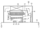
図1及び図2において、同期電動機または発電機として用いられる回転電機10は、突極形回転子11、及びその外周を所定の間隔を保って囲む固定子12を有する。これら突極形回転子11及びその外周を囲む固定子12は、閉鎖形のフレーム13内に設けられている。このフレーム13内における突極形回転子11の回転軸15の一端側には送風用のファン16が設けられており、回転軸15の回転に伴いラジアル方向に送風する。
閉鎖型フレーム13の内面と固定子12の外面側に設けられた導風板17との間には、冷却器18が設けられている。ファン16により送風された空気は、フレーム13の内面、及び導風板17の外面(図示上面)に案内されて冷却器18に送られ、この冷却器18を図示左方へ通過する際、冷却され、突極形回転子11の反対側端部(図示左端側)に送られる。そして、この反対側端部(片端側)から固定子12及び突極形回転子11に向かって図示右方へ流れる。
突極形回転子11は、前述した回転軸15の外周に、ボス21により一体的に取り付けられた円板状のスポーク22、及びこのスポーク22の外周に内周面が一体的に取り付けられている円筒状のリブ23を有する。このリブ23の外周面には、図2で示すように、複数個の突極25が放射状に形成され、かつ、それぞれ図1で示すように、回転軸15の軸方向に沿って配置されている。これら各突極25の周囲には、それぞれ界磁巻線26が巻回されている。
ここで、突極形回転子11を構成する円板状のスポークは、この突極形回転子11の、前述した冷却気送り込み側とは反対側の図示右側、すなわち、冷却気の反送り込み側端部に偏倚させて設けている。したがって、回転軸15の外周と円筒状のリブ23の内周との間には、このリブ23の軸方向の全域にわたって送風用の空間27が生じる。また、円筒状のリブ23には、その内側に形成された空間27から複数個の突極25間に通じる複数個の貫通孔231を、リブ23の周面のほぼ全域にわたって設ける。
上記構成において、回転電機10の運転時、突極形回転子11は、その回転軸15を中心に一体的に回転する。この回転に伴いファン16によりフレーム13内の空気はラジアル方向に送風される。ラジアル方向に送風された空気は、フレーム13の内面及び風導板17により冷却器18に案内される。そして、この冷却器18を図示左方へ通過する際、冷却され冷却気となる。なお、冷却器18は、図示しないが多数の冷却パイプを有し、これら冷却パイプ内には外部から冷媒(液体又は気体)が供給されており、フレーム13内の空気との熱交換によりこれを冷却する。
冷却器18を通過した低温空気は、冷却気としてフレーム13内の図示左方から、突極形回転子11及び固定子12へ向けて図示右向きに送風される。この冷却気は、固定子12の巻線端121を冷却すると共に固定子12と突極形回転子11との間に流れ、さらに、円筒状のリブ23内の空間27に流れる。
固定子12と突極形回転子11との間に流れた冷却気は、従来と同様に、一部は固定子12の鉄心の半径方向に形成された通風ダクト(図示省略)を通って固定子12を冷却しながらその外側に流れ、風導板17の内面(図示下面)を図示右側に流れて、ファン16の吸気側(図示左側)に達する。また、固定子12と突極形回転子11との間に流れた冷却気の残りは、リブ23の外周に放射状に形成された複数の突極25間を軸方向に沿って流れ、これら複数の突極25を冷却したのち、ファン16の吸気側に達する。
円筒状のリブ23内に流れた冷却気は、その下流端(図示右端)が円板状のスポーク22によって塞がれていることから、リブ23の周面に設けられた貫通孔231を通り、前述した複数の突極25間に流れる。すなわち、これら貫通孔231を通って複数の突極25間に冷却気が供給され、しかも軸方向の下流側(図示右側)へも十分な冷却気が供給されることから、突極形回転子11全体をほぼ均一に冷却することができる。
また、固定子12についても、貫通孔231を通って突極形回転子11との間に供給される空気量が加わることから、その半径方向に設けられた図示しない通風ダクトへの通風量も増大し、全体的にほぼ均一な冷却が可能となる。
図3で示す実施の形態では、円板状のスポーク22に、その表裏を貫通する通気孔221を設けている。図1の実施形態では、円筒状のリブ23の図示右端を円板状のスポーク22によって塞ぎ、円筒状のリブ23内に流れた冷却気が、リブ23の周面に設けられた貫通孔231を通って流れるように構成しているが、この場合、全体的な通風抵抗が大きくなり過ぎることがある。このように通風抵抗が大きくなり過ぎると、全体的な通風量が減少することから、円板状のスポーク22に、その表裏を貫通する通気孔221を設け、通風抵抗が過度に大きくならないように調整する。
このように通気孔221を設けたことにより、その通気面積を調整することで、全体的に見て十分な通風量が得られ、しかも、貫通孔231を通って複数の突極25間に十分な空気量を供給できるような通風抵抗に調整することができる。
また、円筒状のリブ23の内周面と対向する回転軸15の外周部分(空間27内)に、図1及び図3で示すように、放電抵抗31を取り付け(巻き付け)てもよい。すなわち、回転電機10が同期電動機の場合、その起動時に、起動トルクを得るため界磁巻線26を短絡する放電抵抗31が用いられる。この放電抵抗31は通電により発熱するので、冷却気が集中的に通気される円筒状のリブ23内の空間27に設置する。
このように構成すれば、通電により発熱した放電抵抗31を有効に冷却することができる。
さらに、上述した放電抵抗31の外周に、図1で示すように、回転軸15の軸方向に沿ってフィン32を一体的に設けてもよい。このフィン32は回転軸15と共に回転し、放射方向への送風気を生じる。
このように構成することにより、放電抵抗31の熱をさらに有効に放熱できると共に、放射方向への送風気を生じることから、空間27内の空気をリブ23に設けた貫通孔231へ向けてより一層効率的に送風することができる。
本発明のいくつかの実施形態を説明したが、これらの実施形態は例として提示したものであり、発明の範囲を限定することは意図していない。これら新規な実施形態は、その他のさまざまな形態で実施されることが可能であり、発明の要旨を逸脱しない範囲で、種々の省略、置き換え、変更を行うことができる。これらの実施形態やその変形は、発明の範囲や要旨に含まれると共に、特許請求の範囲に記載された発明とその均等の範囲に含まれる。
10…回転電機
11…突極形回転子
12…固定子
15…回転軸
22…円板状のスポーク
221…通気孔
23…円筒状のリブ
231…貫通孔
25…突極
31…放電抵抗
32…フィン
11…突極形回転子
12…固定子
15…回転軸
22…円板状のスポーク
221…通気孔
23…円筒状のリブ
231…貫通孔
25…突極
31…放電抵抗
32…フィン
Claims (4)
- 突極形回転子、及びこの突極形回転子の外周を所定の間隔を保って囲む固定子を有し、この突極形回転子の軸方向片端側から冷却気が送り込まれる通風冷却式の回転電機であって、
前記突極形回転子は、回転軸と、この回転軸の外周に一体的に取り付けられた円板状のスポーク、及びこの円板状のスポークの外周に内周面が一体的に取り付けられている円筒状のリブと、前記円筒状のリブの外周面に放射状に配置されそれぞれ回転軸の軸方向に沿って形成された複数個の突極とを有し、
前記円板状のスポークを、前記突極形回転子の、前記冷却気の反送り込み側端部に設け、かつ前記円筒状のリブにはその内側の空間から前記複数個の突極間に通じる貫通孔を設けた
ことを特徴とする回転電機。 - 前記円板状のスポークに、その表裏を貫通する通気孔を設けたことを特徴とする請求項1に記載の回転電機。
- 前記円筒状のリブの内周面と対向する前記回転軸の外周部分に放電抵抗を取り付けたことを特徴とする請求項1に記載の回転電機。
- 前記放電抵抗の外周に、前記回転軸の軸方向に沿ってフィンを一体的に設けて、前記回転軸と共に回転させ、放射方向への送風気を生じさせることを特徴とする請求項3に記載の回転電機。
Priority Applications (2)
| Application Number | Priority Date | Filing Date | Title |
|---|---|---|---|
| US15/580,950 US10516309B2 (en) | 2015-06-19 | 2016-06-20 | Rotating machine |
| CN201680034879.9A CN107710562B (zh) | 2015-06-19 | 2016-06-20 | 旋转电机 |
Applications Claiming Priority (2)
| Application Number | Priority Date | Filing Date | Title |
|---|---|---|---|
| JP2015-123925 | 2015-06-19 | ||
| JP2015123925A JP6637683B2 (ja) | 2015-06-19 | 2015-06-19 | 回転電機 |
Publications (1)
| Publication Number | Publication Date |
|---|---|
| WO2016203778A1 true WO2016203778A1 (ja) | 2016-12-22 |
Family
ID=57545522
Family Applications (1)
| Application Number | Title | Priority Date | Filing Date |
|---|---|---|---|
| PCT/JP2016/002961 Ceased WO2016203778A1 (ja) | 2015-06-19 | 2016-06-20 | 回転電機 |
Country Status (4)
| Country | Link |
|---|---|
| US (1) | US10516309B2 (ja) |
| JP (1) | JP6637683B2 (ja) |
| CN (1) | CN107710562B (ja) |
| WO (1) | WO2016203778A1 (ja) |
Families Citing this family (5)
| Publication number | Priority date | Publication date | Assignee | Title |
|---|---|---|---|---|
| KR102146187B1 (ko) * | 2019-02-27 | 2020-08-19 | 주식회사 남원터보원 | 터보 블로어의 모터 냉각 공기의 온도 저감 구조 |
| KR200491905Y1 (ko) * | 2019-04-11 | 2020-06-29 | 최성수 | 발전기 또는 전동기용 회전자 |
| JP7189835B2 (ja) * | 2019-05-09 | 2022-12-14 | 東芝三菱電機産業システム株式会社 | 同期回転電機および放電抵抗器 |
| US12476519B2 (en) * | 2020-12-24 | 2025-11-18 | Mitsubishi Electric Corporation | Electric motor having fan with through-hole and cylindrical guide facing bracket |
| JP2023106868A (ja) * | 2022-01-21 | 2023-08-02 | 三菱重工業株式会社 | 電動推進器 |
Citations (4)
| Publication number | Priority date | Publication date | Assignee | Title |
|---|---|---|---|---|
| JPS57170674U (ja) * | 1981-04-23 | 1982-10-27 | ||
| JPS63160065U (ja) * | 1987-04-09 | 1988-10-19 | ||
| JPH04368450A (ja) * | 1991-06-13 | 1992-12-21 | Toshiba Corp | 突極形回転電機 |
| JP2003250248A (ja) * | 2002-02-22 | 2003-09-05 | Nissan Motor Co Ltd | 回転電機 |
Family Cites Families (11)
| Publication number | Priority date | Publication date | Assignee | Title |
|---|---|---|---|---|
| JPS55143666U (ja) * | 1979-04-02 | 1980-10-15 | ||
| ATE13372T1 (de) * | 1980-11-28 | 1985-06-15 | Square D Starkstrom Gmbh | Kontaktvorrichtung. |
| JPS57170674A (en) * | 1981-04-13 | 1982-10-20 | Fuji Photo Film Co Ltd | Electronic camera |
| US5214325A (en) * | 1990-12-20 | 1993-05-25 | General Electric Company | Methods and apparatus for ventilating electric machines |
| JPH0690547A (ja) * | 1992-07-21 | 1994-03-29 | Fuji Electric Co Ltd | 突極形回転電機の通風冷却装置 |
| FR2800931B1 (fr) * | 1999-11-09 | 2004-01-23 | Alstom | Dispositif de ventilation et moteur electrique de traction ferroviaire equipe d'un tel dispositif |
| JP4686228B2 (ja) * | 2005-03-23 | 2011-05-25 | 株式会社東芝 | 全閉外扇形電動機 |
| DE102005044327B4 (de) * | 2005-09-16 | 2008-04-17 | Siemens Ag | Elektrische Maschine mit Permanentmagneten |
| CN103636103B (zh) * | 2011-06-30 | 2015-07-29 | 株式会社日立制作所 | 旋转电机 |
| EP2660955B1 (en) * | 2012-05-02 | 2019-07-17 | ABB Schweiz AG | An electric machine |
| JP5918656B2 (ja) * | 2012-08-28 | 2016-05-18 | 東芝三菱電機産業システム株式会社 | 回転電機 |
-
2015
- 2015-06-19 JP JP2015123925A patent/JP6637683B2/ja active Active
-
2016
- 2016-06-20 WO PCT/JP2016/002961 patent/WO2016203778A1/ja not_active Ceased
- 2016-06-20 US US15/580,950 patent/US10516309B2/en active Active
- 2016-06-20 CN CN201680034879.9A patent/CN107710562B/zh active Active
Patent Citations (4)
| Publication number | Priority date | Publication date | Assignee | Title |
|---|---|---|---|---|
| JPS57170674U (ja) * | 1981-04-23 | 1982-10-27 | ||
| JPS63160065U (ja) * | 1987-04-09 | 1988-10-19 | ||
| JPH04368450A (ja) * | 1991-06-13 | 1992-12-21 | Toshiba Corp | 突極形回転電機 |
| JP2003250248A (ja) * | 2002-02-22 | 2003-09-05 | Nissan Motor Co Ltd | 回転電機 |
Also Published As
| Publication number | Publication date |
|---|---|
| CN107710562B (zh) | 2020-06-30 |
| US10516309B2 (en) | 2019-12-24 |
| CN107710562A (zh) | 2018-02-16 |
| JP6637683B2 (ja) | 2020-01-29 |
| JP2017011853A (ja) | 2017-01-12 |
| US20180175688A1 (en) | 2018-06-21 |
Similar Documents
| Publication | Publication Date | Title |
|---|---|---|
| WO2016203778A1 (ja) | 回転電機 | |
| US9800118B2 (en) | Self-cooled motor | |
| KR101714477B1 (ko) | 무인항공로봇의 동력원용 유선형 블레이드를 가지는 외전형 모터 | |
| US9800117B2 (en) | Self-cooled motor | |
| JP2014033584A (ja) | 回転電機の風冷構造 | |
| JP6625671B2 (ja) | 送風装置用電気モータ及び送風装置 | |
| JP2015047034A (ja) | アキシャルギャップ型発電機 | |
| JP2015208101A (ja) | かご形電動機 | |
| US9755467B2 (en) | Open-type induction motor | |
| KR20190096408A (ko) | 풍력 터빈 발전기의 스테이터를 위한 스테이터 지지대, 그러한 스테이터 지지대를 포함하는 스테이터, 발전기, 및 풍력 터빈 | |
| CN102780319A (zh) | 一种隔爆型电动机的导风结构 | |
| JP2017135932A (ja) | アウターロータ型回転電機 | |
| JP6988108B2 (ja) | 回転電機 | |
| JP5918656B2 (ja) | 回転電機 | |
| KR101668547B1 (ko) | 회전 전기기계 | |
| JP2016100953A (ja) | 回転電機 | |
| JP7210373B2 (ja) | 回転電機 | |
| US20160149471A1 (en) | Cooling arrangement | |
| JP2008043149A (ja) | 電動機の冷却構造 | |
| EP3314128B1 (en) | A fan and a ventilation group comprising the fan | |
| JP5723855B2 (ja) | 回転電機 | |
| US2255910A (en) | Blower for field coils | |
| JP2017200354A (ja) | ブラシレス回転電機 | |
| US972850A (en) | Rotary field member of dynamo-electric machines. | |
| JP2025034666A (ja) | 回転電機 |
Legal Events
| Date | Code | Title | Description |
|---|---|---|---|
| 121 | Ep: the epo has been informed by wipo that ep was designated in this application |
Ref document number: 16811253 Country of ref document: EP Kind code of ref document: A1 |
|
| WWE | Wipo information: entry into national phase |
Ref document number: 15580950 Country of ref document: US |
|
| NENP | Non-entry into the national phase |
Ref country code: DE |
|
| 122 | Ep: pct application non-entry in european phase |
Ref document number: 16811253 Country of ref document: EP Kind code of ref document: A1 |