WO2016199534A1 - モータ内蔵スピンドル用玉軸受 - Google Patents
モータ内蔵スピンドル用玉軸受 Download PDFInfo
- Publication number
- WO2016199534A1 WO2016199534A1 PCT/JP2016/064113 JP2016064113W WO2016199534A1 WO 2016199534 A1 WO2016199534 A1 WO 2016199534A1 JP 2016064113 W JP2016064113 W JP 2016064113W WO 2016199534 A1 WO2016199534 A1 WO 2016199534A1
- Authority
- WO
- WIPO (PCT)
- Prior art keywords
- bearing
- spindle
- cage
- motor
- built
- Prior art date
Links
Images


Classifications
-
- F—MECHANICAL ENGINEERING; LIGHTING; HEATING; WEAPONS; BLASTING
- F16—ENGINEERING ELEMENTS AND UNITS; GENERAL MEASURES FOR PRODUCING AND MAINTAINING EFFECTIVE FUNCTIONING OF MACHINES OR INSTALLATIONS; THERMAL INSULATION IN GENERAL
- F16C—SHAFTS; FLEXIBLE SHAFTS; ELEMENTS OR CRANKSHAFT MECHANISMS; ROTARY BODIES OTHER THAN GEARING ELEMENTS; BEARINGS
- F16C37/00—Cooling of bearings
- F16C37/007—Cooling of bearings of rolling bearings
-
- F—MECHANICAL ENGINEERING; LIGHTING; HEATING; WEAPONS; BLASTING
- F16—ENGINEERING ELEMENTS AND UNITS; GENERAL MEASURES FOR PRODUCING AND MAINTAINING EFFECTIVE FUNCTIONING OF MACHINES OR INSTALLATIONS; THERMAL INSULATION IN GENERAL
- F16C—SHAFTS; FLEXIBLE SHAFTS; ELEMENTS OR CRANKSHAFT MECHANISMS; ROTARY BODIES OTHER THAN GEARING ELEMENTS; BEARINGS
- F16C33/00—Parts of bearings; Special methods for making bearings or parts thereof
- F16C33/30—Parts of ball or roller bearings
- F16C33/38—Ball cages
- F16C33/3837—Massive or moulded cages having cage pockets surrounding the balls, e.g. machined window cages
- F16C33/3843—Massive or moulded cages having cage pockets surrounding the balls, e.g. machined window cages formed as one-piece cages, i.e. monoblock cages
-
- F—MECHANICAL ENGINEERING; LIGHTING; HEATING; WEAPONS; BLASTING
- F16—ENGINEERING ELEMENTS AND UNITS; GENERAL MEASURES FOR PRODUCING AND MAINTAINING EFFECTIVE FUNCTIONING OF MACHINES OR INSTALLATIONS; THERMAL INSULATION IN GENERAL
- F16C—SHAFTS; FLEXIBLE SHAFTS; ELEMENTS OR CRANKSHAFT MECHANISMS; ROTARY BODIES OTHER THAN GEARING ELEMENTS; BEARINGS
- F16C33/00—Parts of bearings; Special methods for making bearings or parts thereof
- F16C33/72—Sealings
- F16C33/76—Sealings of ball or roller bearings
- F16C33/78—Sealings of ball or roller bearings with a diaphragm, disc, or ring, with or without resilient members
- F16C33/7816—Details of the sealing or parts thereof, e.g. geometry, material
- F16C33/782—Details of the sealing or parts thereof, e.g. geometry, material of the sealing region
- F16C33/7823—Details of the sealing or parts thereof, e.g. geometry, material of the sealing region of sealing lips
-
- F—MECHANICAL ENGINEERING; LIGHTING; HEATING; WEAPONS; BLASTING
- F16—ENGINEERING ELEMENTS AND UNITS; GENERAL MEASURES FOR PRODUCING AND MAINTAINING EFFECTIVE FUNCTIONING OF MACHINES OR INSTALLATIONS; THERMAL INSULATION IN GENERAL
- F16C—SHAFTS; FLEXIBLE SHAFTS; ELEMENTS OR CRANKSHAFT MECHANISMS; ROTARY BODIES OTHER THAN GEARING ELEMENTS; BEARINGS
- F16C33/00—Parts of bearings; Special methods for making bearings or parts thereof
- F16C33/72—Sealings
- F16C33/76—Sealings of ball or roller bearings
- F16C33/78—Sealings of ball or roller bearings with a diaphragm, disc, or ring, with or without resilient members
- F16C33/784—Sealings of ball or roller bearings with a diaphragm, disc, or ring, with or without resilient members mounted to a groove in the inner surface of the outer race and extending toward the inner race
- F16C33/7843—Sealings of ball or roller bearings with a diaphragm, disc, or ring, with or without resilient members mounted to a groove in the inner surface of the outer race and extending toward the inner race with a single annular sealing disc
- F16C33/7846—Sealings of ball or roller bearings with a diaphragm, disc, or ring, with or without resilient members mounted to a groove in the inner surface of the outer race and extending toward the inner race with a single annular sealing disc with a gap between the annular disc and the inner race
-
- F—MECHANICAL ENGINEERING; LIGHTING; HEATING; WEAPONS; BLASTING
- F16—ENGINEERING ELEMENTS AND UNITS; GENERAL MEASURES FOR PRODUCING AND MAINTAINING EFFECTIVE FUNCTIONING OF MACHINES OR INSTALLATIONS; THERMAL INSULATION IN GENERAL
- F16C—SHAFTS; FLEXIBLE SHAFTS; ELEMENTS OR CRANKSHAFT MECHANISMS; ROTARY BODIES OTHER THAN GEARING ELEMENTS; BEARINGS
- F16C19/00—Bearings with rolling contact, for exclusively rotary movement
- F16C19/02—Bearings with rolling contact, for exclusively rotary movement with bearing balls essentially of the same size in one or more circular rows
- F16C19/14—Bearings with rolling contact, for exclusively rotary movement with bearing balls essentially of the same size in one or more circular rows for both radial and axial load
- F16C19/16—Bearings with rolling contact, for exclusively rotary movement with bearing balls essentially of the same size in one or more circular rows for both radial and axial load with a single row of balls
- F16C19/163—Bearings with rolling contact, for exclusively rotary movement with bearing balls essentially of the same size in one or more circular rows for both radial and axial load with a single row of balls with angular contact
-
- F—MECHANICAL ENGINEERING; LIGHTING; HEATING; WEAPONS; BLASTING
- F16—ENGINEERING ELEMENTS AND UNITS; GENERAL MEASURES FOR PRODUCING AND MAINTAINING EFFECTIVE FUNCTIONING OF MACHINES OR INSTALLATIONS; THERMAL INSULATION IN GENERAL
- F16C—SHAFTS; FLEXIBLE SHAFTS; ELEMENTS OR CRANKSHAFT MECHANISMS; ROTARY BODIES OTHER THAN GEARING ELEMENTS; BEARINGS
- F16C19/00—Bearings with rolling contact, for exclusively rotary movement
- F16C19/52—Bearings with rolling contact, for exclusively rotary movement with devices affected by abnormal or undesired conditions
- F16C19/527—Bearings with rolling contact, for exclusively rotary movement with devices affected by abnormal or undesired conditions related to vibration and noise
Definitions
- the present invention relates to a ball bearing for a small spindle, particularly a motor built-in spindle.
- Small spindle is mainly used for light load machining such as aluminum machining.
- the spindle with a built-in motor has a motor 2 built in the housing 1 of the spindle, the periphery of the motor 2 serves as a heat generation source. Therefore, it is necessary to cool the bearing 3 together with the motor 2.
- the method of cooling the inside of the spindle housing 1 with a liquid is not only complicated but also difficult in terms of space, for example, the structure needs to be sealed.
- the cooling in the housing 1 of the spindle with a built-in motor is mainly performed with air that does not require a complicated structure.
- the air that cools the inside of the spindle housing 1 cools the motor 2 and then the bearing 3 from the rear side by a vent hole 4 installed in the spindle housing 1, and the spindle housing 1 starts from the tip of the spindle housing 1. 1 is discharged to the outside.
- the tip of the spindle housing 1 also serves as a seal against flying objects, and the pressure inside the spindle housing 1 is increased by an air curtain and a labyrinth seal so that cutting fluid, work pieces, etc. are contained in the spindle housing 1. Preventing intrusion.
- the bearing 3 used for the spindle with a built-in motor is filled with grease as a lubricant, and as shown in FIG. 4, both end surfaces are sealed with seal plates 5, but air for cooling the inside of the housing 1 of the spindle is used. If it passes through the inside of the bearing 3, the lubricant may leak to the outside.
- a labyrinth structure is formed between the inner diameter portion of the seal plate 5 and the outer diameter portion of the inner ring 6, and the inner diameter portion of the seal plate 5 is the outer diameter of the inner ring 6. It fits in the seal groove 7 provided in the part.
- reference numeral 8 denotes a cage
- 9 denotes an outer ring
- 10 denotes a rolling element.
- the labyrinth structure prevents the air that has entered the inside of the bearing 3 from being discharged by the seal plate 5, and the air that has entered the inside of the bearing 3 causes turbulent flow inside the bearing 3 as indicated by the arrows in FIG. 4.
- the cage 8 may be vibrated.
- the vibration of the cage 8 is transmitted to the spindle housing 1 and adversely affects the quietness.
- the present invention is designed so that when cooling air enters the bearing of the spindle with a built-in motor, the air is smoothly discharged outside the bearing without causing turbulent flow inside the bearing. It is an object of the present invention to provide a ball bearing for a spindle with a built-in motor that is less susceptible to vibration and has high quietness.
- a ball bearing for a spindle with a built-in motor having a seal plate projecting toward the inner ring side on the inner diameter surface of the bearing the bearing center end of the inner diameter surface of the seal plate and the outer surface in the axial direction of the cage are the same surface, or the seal plate
- the bearing center end of the inner diameter surface of the seal plate is positioned closer to the center side in the axial direction than the outer surface in the axial direction of the cage, and the tip in the bearing center direction of the inner diameter surface of the seal plate and the outer surface in the axial direction of the cage An overlap portion is formed between them.
- the inner diameter surface of the seal plate is parallel to the outer diameter surface of the inner ring, or is inclined so that the bearing center side has a small diameter and a large diameter toward the outside of the bearing.
- the circumferential contact portion of the cage pocket with the rolling element is preferably positioned on the outer diameter side of the rolling element PCD.
- the inner diameter portion of the cage is located on the outer diameter side of the rolling element PCD.
- a grease pocket for enclosing grease is provided in the inner diameter portion of the outer ring.
- the tip in the bearing center direction of the inner surface of the seal plate and the outer surface in the axial direction of the cage are the same surface, or the inner surface of the seal plate If an overlap portion is formed between the tip of the bearing in the center direction of the bearing and the outer surface of the cage in the axial direction, when the cooling air passes through the bearing of the spindle with a built-in motor, the cooling air enters the cage side. Therefore, the turbulent flow of cooling air inside the bearing is unlikely to occur, the cooling air is smoothly discharged outside the bearing, and the cage vibration due to the collision between the cooling air and the cage can be prevented. High silence can be maintained.
- the ball bearing for spindle with a built-in motor is an angular ball bearing.
- the angular ball bearing according to the present invention includes an inner ring 11, an outer ring 12, a rolling element 13 disposed on the rolling surfaces of the inner ring 11 and the outer ring 12 facing each other, a cage 14 that holds the rolling element 13, and an inner ring. 11 and seal plates 15 provided on both end faces of the outer ring 12.
- the seal plate 15 is mounted in a mounting groove 16 provided on the inner diameter surface of the outer ring 12.
- the outer diameter surface 11 a of the inner ring 11 facing the inner diameter portion of the seal plate 15 is formed in a straight line, and between the inner diameter portion of the seal plate 15 and the outer diameter surface of the inner ring 11, Unlike the conventional bearing shown in FIG. 4, the seal groove forming the labyrinth structure is not formed.
- the bearing center direction tip 15a of the inner diameter surface of the seal plate 15 and the outer side surface 14a of the cage 14 in the axial direction are the same surface, or, as shown in FIG.
- the bearing 14 is positioned closer to the center side in the axial direction than the outer side surface 14a in the axial direction, and between the bearing center direction tip 15a of the inner diameter surface of the seal plate 15 and the outer side surface 14a in the axial direction of the cage 14.
- An overlap portion A is formed.
- the bearing center direction tip 15a of the inner diameter surface of the seal plate 15 and the outer side surface 14a of the cage 14 in the axial direction are the same surface, or the bearing center direction tip 15a of the inner diameter surface of the seal plate 15 and the cage. If the overlap portion A is formed between the outer surface 14a in the axial direction of 14 and the cooling air passes through the bearing of the motor built-in spindle, the cooling air is prevented from entering the cage 14 side. Further, turbulent flow of the cooling air inside the bearing hardly occurs, and vibration of the cage 14 due to collision between the cooling air and the cage 14 can be prevented.
- the inner diameter surface of the seal plate 15 is parallel to the outer diameter surface 11a of the inner ring 11, or is inclined so that the bearing center side has a small diameter and increases toward the outer side of the bearing.
- the angle ⁇ formed between the intersection B of the outer diameter surface 11a of the inner ring 11 on the extension line of the inner diameter surface of the seal plate 15 and the inner diameter surface of the seal plate 15 is determined by the cooling air that has directly collided with the outer diameter surface 11a of the inner ring 11. It is desirable to set the angle to suppress the collision with the cage 14.
- 2 and 3 are partially enlarged views showing the guide state of the cage 14 of the embodiment of the ball bearing for a spindle with a built-in motor according to the present invention.
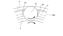
- the alternate long and two short dashes line indicates the pitch circle diameter (PCD) of the rolling element 13
- reference numeral 14 b indicates a pocket that accommodates the rolling element 13.
- the size of the inner diameter portion 14c of the cage 14 is preferably larger than the inner diameter size of the seal plate 15 so as not to hinder the passage of air.
- FIG. A structure in which the circumferential contact portion 14e with the rolling element 13 of 14b is on the outer diameter side than the PCD of the rolling element 13 is more preferable.
- the circumferential contact portion 14e of the pocket 14b of the cage 14 with the rolling element 13 is located on the outer diameter side of the PCD of the rolling element 13, so that the rolling element 13 moves in the circumferential direction as shown by the thick arrow.
- a force in the outer diameter direction always acts on the retainer 14, a clearance between the retainer 14 and the outer diameter surface 11a of the inner ring 11 is secured, and passage of air is not hindered.
- the inner diameter portion 14 c of the cage 14 is more than the PCD of the rolling element 13 so that a force in the outer diameter direction always acts on the cage 14 with respect to the circumferential movement of the rolling element 13. It may be located on the outer diameter side.
- the circumferential contact portion 8b of the pocket 8a of the cage 8 with the rolling element 10 is on the PCD of the rolling element 10, but the embodiment of the present invention shown in FIG. Then, the circumferential direction contact part 14e with the rolling element 13 of the pocket 14b of the holder
- retainer 14 is located in the outer diameter side rather than PCD of a rolling element.
- a grease pocket 17 is provided in the part.
- the orientation of the bearing differs between the two rows with respect to the air flow, so that the grease pockets 17 are formed on the left and right sides of the bearing. .
- the amount of grease filled is 40% to 50% of the static space volume. If it is 40% or less, a stable durability effect cannot be obtained due to the bias of grease due to air pressure. In the case of 50% or more, due to grease bias due to air pressure, excessive rewinding of grease leads to large temperature fluctuations and vibration fluctuations, and stable rotation cannot be obtained.
- the base oil viscosity of the grease is preferably 20 to 40 mm 2 / s.
Landscapes
- Engineering & Computer Science (AREA)
- General Engineering & Computer Science (AREA)
- Mechanical Engineering (AREA)
- Rolling Contact Bearings (AREA)
- Mounting Of Bearings Or Others (AREA)
- Sealing Of Bearings (AREA)
Abstract
モータ内蔵スピンドルの軸受内に冷却エアが侵入した際に、エアが軸受内部で乱流を起こすことなく、エアが軸受外部に排出され、保持器14の振動が生じ難く、静粛性の高いモータ内蔵スピンドル用玉軸受を提供することを課題とする。シール板15の内径面の軸受中心方向先端15aを、保持器14の軸方向の外側面14aよりも軸方向の中心側に位置させて、シール板15の内径面の軸受中心方向先端15aと保持器14の軸方向の外側面14aとの間にオーバーラップ部Aを形成し、軸受の内部を冷却エアが通過する際に、冷却エアの保持器14側への侵入を抑制して、冷却エアがスムーズに軸受外部に排出されるようにした。
Description
この発明は、小型スピンドル、特にモータ内蔵スピンドル用玉軸受に関するものである。
小型スピンドルは、主にアルミ加工などの軽負荷加工に用いられている。
近年、小型スピンドルは、図6に示すように、コンパクト化を目的にスピンドルのハウジング1内にモータ2を内蔵したタイプが多くなってきている(特許文献1~3)。なお、図6において、被加工物は、符号Wで示している。
この種のモータ内蔵スピンドル用玉軸受3としては、高速性を求められることから、アンギュラ玉軸受を使用することが多い。
モータ内蔵スピンドルは、スピンドルのハウジング1内にモータ2を内蔵していることから、モータ2の周辺が発熱源となるので、モータ2と共に、軸受3を冷却する必要がある。
スピンドルのハウジング1内を液体で冷却する方法は、構造にシール性が必要になる等、構造が複雑になるばかりか、スペース的にも困難であることが多い。
このため、モータ内蔵スピンドルのハウジング1内の冷却には、複雑な構造が不要なエアでの冷却が主流になっている。
このスピンドルのハウジング1内を冷却するエアは、スピンドルのハウジング1に設置された通気孔4により、後ろ側からモータ2、次に軸受3を冷却し、スピンドルのハウジング1の先端部からスピンドルのハウジング1の外部に排出される。
スピンドルのハウジング1の先端部は、飛来物に対するシールを兼ねており、エアカーテン、ラビリンスシールにより、スピンドルのハウジング1の内部の圧力を高くし、切削液、加工片等がスピンドルのハウジング1内に侵入することを防止している。
ところで、スピンドルのハウジング1内を冷却するエアは、軸受3の内部を通過することもあるため、次のような問題がある。
モータ内蔵スピンドルに使用する軸受3は、内部に潤滑剤としてグリースが充填され、図4に示すように、両端面がシール板5によって密封されているが、スピンドルのハウジング1内を冷却するエアが軸受3の内部を通過すると、潤滑剤が外部に漏洩するおそれがある。
潤滑剤が外部に漏えいすると、軸受の耐久性能に影響を及ぼす可能性がある。
また、従来、図4に示すように、シール板5の内径部と、内輪6の外径部との間は、ラビリンス構造になっており、シール板5の内径部が、内輪6の外径部に設けたシール溝7に嵌っている。なお、図4において、符号8は保持器、9は外輪、10は転動体を示している。
上記ラビリンス構造により、軸受3の内部に侵入したエアの排出がシール板5によって妨げられ、図4の矢印に示すように、軸受3の内部に侵入したエアが軸受3の内部で乱流を引き起こして、保持器8を振動させることがある。
保持器8の振動は、スピンドルのハウジング1に振動が伝達され、静粛性にも悪影響を及ぼす。
そこで、この発明は、モータ内蔵スピンドルの軸受内に冷却エアが侵入した際に、エアが軸受内部で乱流を起こすことなく、エアがスムーズに軸受外部に排出されるようにして、保持器の振動が生じ難く、静粛性の高いモータ内蔵スピンドル用玉軸受を提供しようとするものである。
上記の課題を解決するため、この発明においては、内輪と、外輪と、内輪と外輪の対向する転動面に配設された転動体と、転動体を保持する保持器と、外輪の両端部の内径面に内輪側に向かって突出するシール板を有するモータ内蔵スピンドル用玉軸受において、シール板の内径面の軸受中心方向先端と保持器の軸方向の外側面とが同一面、もしくはシール板の内径面の軸受中心方向先端を保持器の軸方向の外側面よりも軸方向の中心側に位置させて、シール板の内径面の軸受中心方向先端と保持器の軸方向の外側面との間にオーバーラップ部を形成したことを特徴とする。
前記シール板の内径面が、内輪の外径面に対して平行、もしくは軸受中心側が小径で、軸受外側に向かって大径になるように傾斜していることが好ましい。
前記保持器のポケットの転動体との周方向接触部は、転動体のPCDよりも外径側に位置することが好ましい。
また、前記保持器の内径部は、転動体のPCDよりも外径側に位置することが好ましい。
また、前記外輪の内径部に、グリースを封入するグリースポケットを設けることが好ましい。
この発明に係るモータ内蔵スピンドル用玉軸受においては、上記のように、シール板の内径面の軸受中心方向先端と保持器の軸方向の外側面とが同一面か、もしくは、シール板の内径面の軸受中心方向先端と保持器の軸方向の外側面との間にオーバーラップ部を形成すると、モータ内蔵スピンドルの軸受内に冷却エアが通過する際に、冷却エアの保持器側への侵入が抑制されるので、軸受内部での冷却エアの乱流が生じ難く、冷却エアがスムーズに軸受外部に排出され、また、冷却エアと保持器との衝突による保持器の振動を防止することができ、高い静粛性を維持することができる。
以下、この発明の実施の形態を添付図面に基づいて説明する。
この発明の一実施形態に係るモータ内蔵スピンドル用玉軸受は、図1に示すように、アンギュラ玉軸受である。
この発明の一実施形態に係るモータ内蔵スピンドル用玉軸受は、図1に示すように、アンギュラ玉軸受である。
この発明に係るアンギュラ玉軸受は、内輪11と、外輪12と、内輪11と外輪12の対向する転動面に配設された転動体13と、転動体13を保持する保持器14と、内輪11と外輪12の両端面に設けられたシール板15とからなる。
シール板15は、外輪12の内径面に設けられた取付溝16に装着されている。
シール板15の内径部と対面する内輪11の外径面11aは、図1に示すように、直線状に形成され、シール板15の内径部と内輪11の外径面との間に、図4に示す従来の軸受のように、ラビリンス構造を形成するシール溝を形成していない。
シール板15の内径面の軸受中心方向先端15aと保持器14の軸方向の外側面14aとが同一面、もしくは、図1に示すように、シール板15の内径面の軸受中心方向先端15aを、保持器14の軸方向の外側面14aよりも軸方向の中心側に位置させて、シール板15の内径面の軸受中心方向先端15aと保持器14の軸方向の外側面14aとの間にオーバーラップ部Aを形成している。
このように、シール板15の内径面の軸受中心方向先端15aと保持器14の軸方向の外側面14aとが同一面か、もしくは、シール板15の内径面の軸受中心方向先端15aと保持器14の軸方向の外側面14aとの間にオーバーラップ部Aを形成すると、モータ内蔵スピンドルの軸受内に冷却エアが通過する際に、冷却エアの保持器14側への侵入が抑制されるので、軸受内部での冷却エアの乱流が生じ難く、また、冷却エアと保持器14との衝突による保持器14の振動を防止することができる。
また、シール板15の内径面は、内輪11の外径面11aに対して平行、もしくは軸受中心側が小径で、軸受外側に向かって大径になるように傾斜している。このシール板15の内径面の延長線上における内輪11の外径面11aの交点Bと、シール板15の内径面とがなす角度αは、内輪11の外径面11aに直接衝突した冷却エアが、保持器14への衝突を抑制する角度にすることが望ましい。
図2及び図3は、それぞれこの発明に係るモータ内蔵スピンドル用玉軸受の実施形態の保持器14の案内状態を示す部分拡大図である。図2及び図3において、二点鎖線は、転動体13のピッチ円直径(PCD)を示し、符号14bは、転動体13を収容するポケットを示している。
次に、保持器14の内径部14cの寸法は、エアの通過を妨げないようシール板15の内径寸法より大きくすることが好ましいが、図2に示すように、回転中の保持器14のポケット14bの転動体13との周方向接触部14eが転動体13のPCDよりも外径側になるような構造がより好ましい。保持器14のポケット14bの転動体13との周方向接触部14eが転動体13のPCDよりも外径側にすることにより、太線の矢印で示すように、転動体13の円周方向運動に対し常に保持器14に外径方向の力が作用するため、保持器14と内輪11の外径面11aとの隙間が確保され、エアの通過が妨げられない。
また、図3に示すように、転動体13の円周方向運動に対し常に保持器14に外径方向の力が作用するよう、保持器14の内径部14cが、転動体13のPCDよりも外径側に位置させてもよい。
即ち、従来例では、図5に示すように、保持器8のポケット8aの転動体10との周方向接触部8bは転動体10のPCD上になるが、図2に示すこの発明の実施形態では、保持器14のポケット14bの転動体13との周方向接触部14eは転動体のPCDよりも外径側に位置している。
また、図1の実施形態では、外輪12の軌道輪と転動体13との間、外輪12の軌道輪と保持器14との間に、安定的に潤滑剤を供給するため、外輪12の一部にグリースポケット17を設けている。
この発明に係るアンギュラ玉軸受を2列の背面合せで使用する場合には、エアの流れに対し軸受の向きが2列間で異なるため、軸受の左右両側にグリースポケット17を形成するようにする。
また、グリース封入量は、静止空間容積の40%~50%とする。40%以下の場合、エア圧よるグリースの偏りにより、安定した耐久効果が得られない。50%以上の場合、エア圧よるグリースの偏りにより、グリースの再巻き込み過多により温度変動大、振動変動に繋がり安定した回転が得られない。なお、グリースの基油粘度は、20~40mm2/sが好ましい。
10 :転動体
11 :内輪
11a :外径面
12 :外輪
13 :転動体
14 :保持器
14a :外側面
14b :ポケット
14c :内径部
14e :周方向接触部
15 :シール板
15a :軸受中心方向先端
16 :取付溝
17 :グリースポケット
11 :内輪
11a :外径面
12 :外輪
13 :転動体
14 :保持器
14a :外側面
14b :ポケット
14c :内径部
14e :周方向接触部
15 :シール板
15a :軸受中心方向先端
16 :取付溝
17 :グリースポケット
Claims (6)
- 内輪と、外輪と、内輪と外輪の対向する転動面に配設された転動体と、転動体を保持する保持器と、外輪の両端部の内径面に内輪側に向かって突出するシール板を有するモータ内蔵スピンドル用玉軸受において、シール板の内径面の軸受中心方向先端と保持器の軸方向の外側面とが同一面、もしくはシール板の内径面の軸受中心方向先端を保持器の軸方向の外側面よりも軸方向の中心側に位置させて、シール板の内径面の軸受中心方向先端と保持器の軸方向の外側面との間にオーバーラップ部を形成したことを特徴とするモータ内蔵スピンドル用玉軸受。
- 前記シール板の内径面が、内輪の外径面に対して平行、もしくは軸受中心側が小径で、軸受外側に向かって大径になるように傾斜していることを特徴とする請求項1記載のモータ内蔵スピンドル用玉軸受。
- 前記保持器のポケットの転動体との周方向接触部は、転動体のPCDよりも外径側に位置することを特徴とする請求項1又は2記載のモータ内蔵スピンドル用玉軸受。
- 前記保持器の内径部が、転動体のPCDよりも外径側に位置することを特徴とする請求項1から3のいずれかに記載のモータ内蔵スピンドル用玉軸受。
- 前記外輪の内径部に、潤滑剤としてグリースを封入した請求項1から4のいずれかに記載のモータ内蔵スピンドル用玉軸受。
- 前記外輪の内径部に、グリースを封入するグリースポケットを設けたことを特徴とする請求項1から5のいずれかに記載のモータ内蔵スピンドル用玉軸受。
Applications Claiming Priority (2)
| Application Number | Priority Date | Filing Date | Title |
|---|---|---|---|
| JP2015116445A JP6560029B2 (ja) | 2015-06-09 | 2015-06-09 | モータ内蔵スピンドル用玉軸受 |
| JP2015-116445 | 2015-06-09 |
Publications (1)
| Publication Number | Publication Date |
|---|---|
| WO2016199534A1 true WO2016199534A1 (ja) | 2016-12-15 |
Family
ID=57504793
Family Applications (1)
| Application Number | Title | Priority Date | Filing Date |
|---|---|---|---|
| PCT/JP2016/064113 WO2016199534A1 (ja) | 2015-06-09 | 2016-05-12 | モータ内蔵スピンドル用玉軸受 |
Country Status (3)
| Country | Link |
|---|---|
| JP (1) | JP6560029B2 (ja) |
| TW (1) | TW201707355A (ja) |
| WO (1) | WO2016199534A1 (ja) |
Families Citing this family (3)
| Publication number | Priority date | Publication date | Assignee | Title |
|---|---|---|---|---|
| JP2018168952A (ja) * | 2017-03-30 | 2018-11-01 | Ntn株式会社 | グリース補給用軸受間座・軸受組およびスピンドル装置 |
| WO2019188621A1 (ja) * | 2018-03-29 | 2019-10-03 | Ntn株式会社 | 軸受装置の冷却構造 |
| JP7050632B2 (ja) * | 2018-09-07 | 2022-04-08 | Ntn株式会社 | 転がり軸受およびこの転がり軸受を備えたスピンドル装置 |
Citations (5)
| Publication number | Priority date | Publication date | Assignee | Title |
|---|---|---|---|---|
| JPH112248A (ja) * | 1997-06-12 | 1999-01-06 | Nippon Seiko Kk | 転がり軸受 |
| JP2004052793A (ja) * | 2002-07-16 | 2004-02-19 | Nsk Ltd | 転がり軸受 |
| JP2009216240A (ja) * | 2008-02-14 | 2009-09-24 | Ntn Corp | 転がり軸受 |
| JP2012180886A (ja) * | 2011-03-01 | 2012-09-20 | Ntn Corp | 保持器および転がり軸受 |
| JP2015086940A (ja) * | 2013-10-30 | 2015-05-07 | 日本精工株式会社 | 転がり軸受 |
-
2015
- 2015-06-09 JP JP2015116445A patent/JP6560029B2/ja active Active
-
2016
- 2016-05-09 TW TW105114290A patent/TW201707355A/zh unknown
- 2016-05-12 WO PCT/JP2016/064113 patent/WO2016199534A1/ja active Application Filing
Patent Citations (5)
| Publication number | Priority date | Publication date | Assignee | Title |
|---|---|---|---|---|
| JPH112248A (ja) * | 1997-06-12 | 1999-01-06 | Nippon Seiko Kk | 転がり軸受 |
| JP2004052793A (ja) * | 2002-07-16 | 2004-02-19 | Nsk Ltd | 転がり軸受 |
| JP2009216240A (ja) * | 2008-02-14 | 2009-09-24 | Ntn Corp | 転がり軸受 |
| JP2012180886A (ja) * | 2011-03-01 | 2012-09-20 | Ntn Corp | 保持器および転がり軸受 |
| JP2015086940A (ja) * | 2013-10-30 | 2015-05-07 | 日本精工株式会社 | 転がり軸受 |
Also Published As
| Publication number | Publication date |
|---|---|
| JP2017002971A (ja) | 2017-01-05 |
| JP6560029B2 (ja) | 2019-08-14 |
| TW201707355A (zh) | 2017-02-16 |
Similar Documents
| Publication | Publication Date | Title |
|---|---|---|
| JP6339433B2 (ja) | モータ内蔵スピンドル用玉軸受 | |
| JP2014137076A (ja) | 転がり軸受装置 | |
| JP2007010026A (ja) | 円筒ころ軸受及び円筒ころ軸受用保持器 | |
| WO2016199534A1 (ja) | モータ内蔵スピンドル用玉軸受 | |
| WO2017163870A1 (ja) | モータ内蔵スピンドル用玉軸受 | |
| JP2014062619A (ja) | 軸受装置の冷却構造 | |
| JP2006329218A (ja) | 転がり軸受用保持器 | |
| JP2008309178A (ja) | 軸受装置 | |
| WO2018034245A1 (ja) | 軸受装置、及び工作機械用主軸装置 | |
| WO2020050337A1 (ja) | 転がり軸受およびこの転がり軸受を備えたスピンドル装置 | |
| WO2018034246A1 (ja) | 玉軸受、及び工作機械用主軸装置 | |
| WO2018181752A1 (ja) | グリース補給用軸受間座、軸受組およびスピンドル装置 | |
| JP2017187119A (ja) | 転がり軸受 | |
| JP2019168021A (ja) | モータ内蔵スピンドル用玉軸受 | |
| WO2017135073A1 (ja) | モータ内蔵スピンドル用玉軸受 | |
| KR20150050260A (ko) | 공작 기계의 주축 구조 | |
| JP6127761B2 (ja) | 円錐ころ軸受と円錐ころ軸受を用いた動力伝達装置 | |
| JP2019011850A (ja) | スラストころ軸受 | |
| WO2018181033A1 (ja) | 軸受装置の冷却構造 | |
| JP2011069456A (ja) | 転がり軸受 | |
| JP2015001273A (ja) | 円錐ころ軸受と円錐ころ軸受を用いた動力伝達装置 | |
| WO2018181524A1 (ja) | 転がり軸受用保持器および外輪給油孔付き転がり軸受 | |
| JP2006125512A (ja) | 円筒ころ軸受 | |
| JP2020173022A (ja) | アンギュラ玉軸受 | |
| JP2015102208A (ja) | 軸受装置及び主軸装置 |
Legal Events
| Date | Code | Title | Description |
|---|---|---|---|
| 121 | Ep: the epo has been informed by wipo that ep was designated in this application |
Ref document number: 16807241 Country of ref document: EP Kind code of ref document: A1 |
|
| NENP | Non-entry into the national phase |
Ref country code: DE |
|
| 122 | Ep: pct application non-entry in european phase |
Ref document number: 16807241 Country of ref document: EP Kind code of ref document: A1 |