WO2016199343A1 - 高圧ポンプ - Google Patents
高圧ポンプ Download PDFInfo
- Publication number
- WO2016199343A1 WO2016199343A1 PCT/JP2016/002289 JP2016002289W WO2016199343A1 WO 2016199343 A1 WO2016199343 A1 WO 2016199343A1 JP 2016002289 W JP2016002289 W JP 2016002289W WO 2016199343 A1 WO2016199343 A1 WO 2016199343A1
- Authority
- WO
- WIPO (PCT)
- Prior art keywords
- relief valve
- valve seat
- space
- discharge
- passage
- Prior art date
- Legal status (The legal status is an assumption and is not a legal conclusion. Google has not performed a legal analysis and makes no representation as to the accuracy of the status listed.)
- Ceased
Links
Images



Classifications
-
- F—MECHANICAL ENGINEERING; LIGHTING; HEATING; WEAPONS; BLASTING
- F02—COMBUSTION ENGINES; HOT-GAS OR COMBUSTION-PRODUCT ENGINE PLANTS
- F02M—SUPPLYING COMBUSTION ENGINES IN GENERAL WITH COMBUSTIBLE MIXTURES OR CONSTITUENTS THEREOF
- F02M59/00—Pumps specially adapted for fuel-injection and not provided for in groups F02M39/00 -F02M57/00, e.g. rotary cylinder-block type of pumps
- F02M59/44—Details, components parts, or accessories not provided for in, or of interest apart from, the apparatus of groups F02M59/02 - F02M59/42; Pumps having transducers, e.g. to measure displacement of pump rack or piston
- F02M59/46—Valves
-
- F—MECHANICAL ENGINEERING; LIGHTING; HEATING; WEAPONS; BLASTING
- F02—COMBUSTION ENGINES; HOT-GAS OR COMBUSTION-PRODUCT ENGINE PLANTS
- F02M—SUPPLYING COMBUSTION ENGINES IN GENERAL WITH COMBUSTIBLE MIXTURES OR CONSTITUENTS THEREOF
- F02M59/00—Pumps specially adapted for fuel-injection and not provided for in groups F02M39/00 -F02M57/00, e.g. rotary cylinder-block type of pumps
- F02M59/02—Pumps specially adapted for fuel-injection and not provided for in groups F02M39/00 -F02M57/00, e.g. rotary cylinder-block type of pumps of reciprocating-piston or reciprocating-cylinder type
- F02M59/025—Pumps specially adapted for fuel-injection and not provided for in groups F02M39/00 -F02M57/00, e.g. rotary cylinder-block type of pumps of reciprocating-piston or reciprocating-cylinder type characterised by a single piston
-
- F—MECHANICAL ENGINEERING; LIGHTING; HEATING; WEAPONS; BLASTING
- F02—COMBUSTION ENGINES; HOT-GAS OR COMBUSTION-PRODUCT ENGINE PLANTS
- F02M—SUPPLYING COMBUSTION ENGINES IN GENERAL WITH COMBUSTIBLE MIXTURES OR CONSTITUENTS THEREOF
- F02M69/00—Low-pressure fuel-injection apparatus ; Apparatus with both continuous and intermittent injection; Apparatus injecting different types of fuel
- F02M69/46—Details, component parts or accessories not provided for in, or of interest apart from, the apparatus covered by groups F02M69/02 - F02M69/44
- F02M69/54—Arrangement of fuel pressure regulators
-
- F—MECHANICAL ENGINEERING; LIGHTING; HEATING; WEAPONS; BLASTING
- F16—ENGINEERING ELEMENTS AND UNITS; GENERAL MEASURES FOR PRODUCING AND MAINTAINING EFFECTIVE FUNCTIONING OF MACHINES OR INSTALLATIONS; THERMAL INSULATION IN GENERAL
- F16K—VALVES; TAPS; COCKS; ACTUATING-FLOATS; DEVICES FOR VENTING OR AERATING
- F16K17/00—Safety valves; Equalising valves, e.g. pressure relief valves
- F16K17/02—Safety valves; Equalising valves, e.g. pressure relief valves opening on surplus pressure on one side; closing on insufficient pressure on one side
- F16K17/04—Safety valves; Equalising valves, e.g. pressure relief valves opening on surplus pressure on one side; closing on insufficient pressure on one side spring-loaded
-
- F—MECHANICAL ENGINEERING; LIGHTING; HEATING; WEAPONS; BLASTING
- F02—COMBUSTION ENGINES; HOT-GAS OR COMBUSTION-PRODUCT ENGINE PLANTS
- F02M—SUPPLYING COMBUSTION ENGINES IN GENERAL WITH COMBUSTIBLE MIXTURES OR CONSTITUENTS THEREOF
- F02M59/00—Pumps specially adapted for fuel-injection and not provided for in groups F02M39/00 -F02M57/00, e.g. rotary cylinder-block type of pumps
- F02M59/02—Pumps specially adapted for fuel-injection and not provided for in groups F02M39/00 -F02M57/00, e.g. rotary cylinder-block type of pumps of reciprocating-piston or reciprocating-cylinder type
- F02M59/10—Pumps specially adapted for fuel-injection and not provided for in groups F02M39/00 -F02M57/00, e.g. rotary cylinder-block type of pumps of reciprocating-piston or reciprocating-cylinder type characterised by the piston-drive
- F02M59/102—Mechanical drive, e.g. tappets or cams
-
- F—MECHANICAL ENGINEERING; LIGHTING; HEATING; WEAPONS; BLASTING
- F02—COMBUSTION ENGINES; HOT-GAS OR COMBUSTION-PRODUCT ENGINE PLANTS
- F02M—SUPPLYING COMBUSTION ENGINES IN GENERAL WITH COMBUSTIBLE MIXTURES OR CONSTITUENTS THEREOF
- F02M59/00—Pumps specially adapted for fuel-injection and not provided for in groups F02M39/00 -F02M57/00, e.g. rotary cylinder-block type of pumps
- F02M59/44—Details, components parts, or accessories not provided for in, or of interest apart from, the apparatus of groups F02M59/02 - F02M59/42; Pumps having transducers, e.g. to measure displacement of pump rack or piston
- F02M59/442—Details, components parts, or accessories not provided for in, or of interest apart from, the apparatus of groups F02M59/02 - F02M59/42; Pumps having transducers, e.g. to measure displacement of pump rack or piston means preventing fuel leakage around pump plunger, e.g. fluid barriers
Definitions
- This disclosure relates to a high-pressure pump that pressurizes and discharges fuel.
- a high pressure pump in which a discharge valve and a relief valve are integrally provided in a discharge passage through which fuel pressurized in a pressurizing chamber flows is known.
- a spherical valve is used as the valve body of the relief valve.
- the high-pressure pump of Patent Document 1 includes a holder that holds a valve body of a relief valve, and a biasing member that biases the valve body toward the valve seat via the holder.
- the movement of the valve body and the holder is not guided by other members, and can move relatively freely in the space on the pressurizing chamber side with respect to the valve seat.
- the fuel discharged from the pressurizing chamber of the high pressure pump flows around the valve body and the holder and is discharged to the outside of the high pressure pump. For this reason, the valve body and the holder may move or vibrate due to the flow of fuel. If the valve element moves or vibrates while the valve element is in contact with the valve seat, the valve seat or the valve element may be worn. If the valve seat or the valve body is worn, the valve opening pressure of the relief valve may change over time.
- valve body and the holder since the valve body and the holder are formed separately, the valve body and the holder may move relative to each other, and the position of the valve body may become unstable. As a result, wear of the valve seat or the valve body may be promoted.
- the present disclosure has been made in view of the above-described points, and an object thereof is to provide a high-pressure pump that can suppress a change over time in the valve opening pressure of a relief valve member.
- the high-pressure pump includes a pump body, a valve seat portion, a discharge valve member, a discharge valve biasing member, a relief valve member, a relief valve biasing member, and a support portion.
- the pump body has a pressurizing chamber for pressurizing the fuel, and a discharge passage through which the fuel pressurized and discharged in the pressurizing chamber flows.
- the valve seat portion has a valve seat portion main body, a discharge valve passage, a relief valve passage, a discharge valve seat, and a relief valve seat.
- the valve seat body is provided in the discharge passage so as to divide the discharge passage into a first space that is a space on the pressurizing chamber side and a second space that is a space on the opposite side of the pressurizing chamber.
- the discharge valve passage is provided in the valve seat body so as to connect the first space and the second space.
- the relief valve passage is provided in the valve seat main body so as to connect the second space and the first space and not to communicate with the discharge valve passage.
- the discharge valve seat is formed in an annular shape around the opening on the second space side of the discharge valve passage of the valve seat body.
- the relief valve seat is formed in an annular shape around the opening on the first space side of the relief valve passage of the valve seat body.
- the discharge valve member is provided in the second space so as to be able to come into contact with the discharge valve seat, and opens and closes the discharge valve passage when separated from the discharge valve seat or in contact with the discharge valve seat.
- the discharge valve biasing member biases the discharge valve member toward the discharge valve seat.
- the relief valve member has a relief valve main body and a relief valve seat portion.
- the relief valve body is formed in a rod shape.
- the relief valve seat portion is formed integrally with the relief valve main body at the first axial end of the relief valve main body so as to be able to contact the relief valve seat.
- the relief valve member is provided in the first space so as to be capable of reciprocating in the axial direction.
- the relief valve biasing member biases the relief valve member toward the relief valve seat.
- the support part has a support part body that slidably supports the outer wall of the relief valve body so as to guide the axial reciprocation of the relief valve member.
- the support body of the support section slidably supports the outer wall of the relief valve body so as to guide the axial reciprocation of the relief valve member. Therefore, even if the fuel discharged from the pressurizing chamber of the high pressure pump flows around the relief valve member, the relief valve seat portion of the relief valve member is prevented from moving or vibrating in the radial direction relative to the relief valve seat. The Thereby, abrasion of a relief valve seat or a relief valve seat part can be controlled. Therefore, it is possible to suppress the change with time of the valve opening pressure of the relief valve member.
- the relief valve seat portion is formed integrally with the relief valve body. Therefore, the relief valve seat portion and the relief valve main body do not move relative to each other. Therefore, for example, the position of the relief valve seat portion is stabilized as compared with a configuration in which the relief valve body and the relief valve seat portion are formed separately. Therefore, wear of the relief valve seat or the relief valve seat portion can be further suppressed.
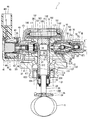
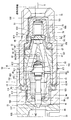
- the schematic diagram which shows the high pressure pump by 1st Embodiment of this indication Sectional drawing which shows the high pressure pump by 1st Embodiment.
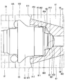
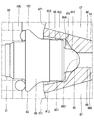
- Sectional drawing which shows the relief valve seat vicinity of the high pressure pump by 2nd Embodiment of this indication The schematic diagram which shows the high pressure pump by 1st Embodiment of this indication.
- FIG. 1 A high pressure pump according to a first embodiment of the present disclosure is shown in FIG. 1
- the high-pressure pump 1 is provided in a vehicle not shown.
- the high-pressure pump 1 is a pump that supplies fuel at a high pressure, for example, to an engine as an internal combustion engine.
- the fuel that the high-pressure pump 1 supplies to the engine is, for example, gasoline. That is, the fuel supply target of the high-pressure pump 1 is a gasoline engine.
- the fuel stored in the fuel tank 2 is supplied to the high-pressure pump 1 via the pipe 4 by the fuel pump 3.
- the high-pressure pump 1 pressurizes the fuel supplied from the fuel pump 3 and discharges it to the fuel rail 7 via the pipe 6.
- the fuel in the fuel rail 7 is accumulated and supplied to the engine from the fuel injection valve 8 connected to the fuel rail 7.
- the high-pressure pump 1 includes a pump body 10, a cover 15, a pulsation damper 16, a plunger 20, a suction valve device 30, an electromagnetic drive unit 40, a discharge valve device 50, and the like.
- the pump body 10 includes an upper housing 11, a lower housing 12, a cylinder 13, a holder support portion 14, a union 51, and the like.
- the upper housing 11 is formed in a substantially rectangular parallelepiped block shape from a metal such as stainless steel.
- the upper housing 11 has a suction hole 111, a discharge hole 112, a cylinder hole 113, a step 114, and the like.
- the suction hole 111 is open at one end in the longitudinal direction of the upper housing 11 and is formed in a substantially cylindrical shape so as to extend in the longitudinal direction.
- the suction passage 101 is formed inside the suction hole 111.
- the discharge hole portion 112 is open at the other end in the longitudinal direction of the upper housing 11 and is formed in a substantially cylindrical shape so as to extend in the longitudinal direction.
- the discharge passage 102 is formed inside the discharge hole 112.
- the suction hole 111 and the discharge hole 112 are formed to be coaxial.
- the cylinder hole 113 is formed in a substantially cylindrical shape between the suction hole 111 and the discharge hole 112 so as to open at both ends in the short direction of the upper housing 11.
- the space inside the cylinder hole 113 is connected to the suction passage 101 and the discharge passage 102.
- the step portion 114 is formed on the inner wall of the upper housing 11 that forms the discharge hole portion 112.
- the discharge hole portion 112 is formed such that the inner diameter on the suction hole portion 111 side with respect to the stepped portion 114 is smaller than the inner diameter on the side opposite to the suction hole portion 111 (see FIGS. 2 and 3).
- the lower housing 12 is formed in a plate shape from a metal such as stainless steel.
- the lower housing 12 has a cylinder hole 121.
- the cylinder hole 121 is formed in a substantially circular shape so as to penetrate the lower housing 12 in the plate thickness direction.
- the lower housing 12 is provided to fit into the upper housing 11 so that the cylinder hole 113 and the cylinder hole 121 are coaxial.
- the upper housing 11 and the lower housing 12 correspond to a “housing” in the claims.
- the cylinder 13 is formed in a bottomed cylindrical shape with a metal such as stainless steel.
- the cylinder 13 has a suction hole 131 and a discharge hole 132.
- the suction hole 131 and the discharge hole 132 are formed in the vicinity of the bottom of the cylinder portion of the cylinder 13 so as to face each other. That is, the suction hole 131 and the discharge hole 132 are formed so as to extend in the radial direction of the cylinder 13 with the axis of the cylinder 13 interposed therebetween.
- the cylinder 13 is inserted through the cylinder hole portion 113 of the upper housing 11 and the cylinder hole portion 121 of the lower housing 12 so that the suction hole 131 is connected to the suction passage 101 and the discharge hole 132 is connected to the discharge passage 102. ing.
- the outer wall at the end on the bottom side of the cylinder 13 is fitted to the inner wall forming the cylinder hole 113 of the upper housing 11.
- the holder support portion 14 is formed in a substantially cylindrical shape from a metal such as stainless steel.
- the holder support portion 14 is provided so that one end thereof is connected to the side opposite to the upper housing 11 of the lower housing 12 so as to be coaxial with the cylinder 13.
- the holder support portion 14 is formed integrally with the lower housing 12.
- the union 51 is formed in a substantially cylindrical shape with a metal such as stainless steel.
- the union 51 is provided so that one end is inserted into the discharge hole 112 of the upper housing 11.
- the union 51 has a screw thread on the outer wall at one end, and the upper housing 11 has a screw groove on the inner wall of the discharge hole portion 112.
- the union 51 is fixed to the upper housing 11 by being screwed into the discharge hole portion 112.
- the union 51 forms a discharge passage 102 on the inner side.
- the union 51 has a stepped portion 52.
- the step portion 52 is formed on the inner wall of the union 51.
- the union 51 is formed such that the inner diameter on the stepped portion 114 side with respect to the stepped portion 52 is larger than the inner diameter on the side opposite to the stepped portion 114 (see FIGS. 2 and 3).
- the other end of the union 51 that is, the end opposite to the upper housing 11 is connected to the end opposite to the fuel rail 7 of the pipe 6.
- the cover 15 is formed in a bottomed cylindrical shape, that is, a cup shape by a metal such as stainless steel.
- the cover 15 accommodates the upper housing 11 on the inner side, and is provided so that the end on the opening side is connected to the outer edge of the lower housing 12.
- the cover 15 and the lower housing 12 are connected by welding over the entire circumference. As a result, the cover 15 and the lower housing 12 are kept liquid-tight.
- a fuel gallery 100 is formed between the inside of the cover 15 and the lower housing 12.
- the cover 15 is provided with an inlet portion (not shown).
- a pipe 4 connected to the fuel pump 3 is connected to the inlet portion. As a result, the fuel in the fuel tank 2 flows into the inside of the cover 15, that is, into the fuel gallery 100 via the inlet portion.
- the cover 15 has a first hole 151 and a second hole 152.
- the first hole 151 and the second hole 152 are formed so as to connect the inner wall and the outer wall of the cover 15, respectively.
- the first hole 151 and the second hole 152 are formed at positions corresponding to the suction hole portion 111 and the discharge hole portion 112 of the upper housing 11, respectively.
- the union 51 is provided so as to be inserted into the second hole 152 of the cover 15 and the discharge hole portion 112 of the upper housing 11.
- the outer wall of the union 51 and the second hole 152 of the cover 15 are welded over the entire circumference. As a result, the union 51 and the cover 15 are kept liquid-tight.
- the pulsation damper 16 is provided between the bottom of the cover 15 and the upper housing 11.
- the pulsation damper 16 is formed, for example, by joining the peripheral portions of two diaphragms, and a gas having a predetermined pressure is sealed inside.
- a locking member 161 is provided near the bottom of the cover 15.
- a damper support portion 162 is provided on the upper housing 11 side of the locking member 161.
- the damper support portion 162 supports the pulsation damper 16 by sandwiching the outer edge portion of the pulsation damper 16 between the engagement member 161 and fitting the engagement member 161.
- the pulsation damper 16 can reduce fuel pressure pulsation by elastically deforming in accordance with changes in fuel pressure in the fuel gallery 100.
- the plunger 20 is formed in a substantially cylindrical shape with a metal such as stainless steel.
- the plunger 20 has a large diameter part 201 and a small diameter part 202.
- the small diameter portion 202 is formed so that the outer diameter is smaller than the outer diameter of the large diameter portion 201.
- the large diameter portion 201 and the small diameter portion 202 are integrally formed coaxially.
- the plunger 20 is provided such that the large diameter portion 201 side is inserted into the cylinder 13.
- the outer diameter of the large-diameter portion 201 of the plunger 20 is substantially the same as the inner diameter of the cylinder 13 or slightly smaller than the inner diameter of the cylinder 13.
- the plunger 20 is supported so that the outer wall of the large-diameter portion 201 slides on the inner wall of the cylinder 13 and can be reciprocated in the axial direction by the cylinder 13.
- a pressurizing chamber 103 is formed between the inner wall of the cylinder part and the bottom part of the cylinder 13 and the outer wall of the end part on the large diameter part 201 side of the plunger 20. The volume of the pressurizing chamber 103 changes when the plunger 20 reciprocates in the cylinder 13.
- the seal holder 21 is provided inside the holder support portion 14.
- the seal holder 21 is formed in a cylindrical shape from a metal such as stainless steel.
- the seal holder 21 is provided such that the outer wall is fitted to the inner wall of the holder support portion 14.
- the seal holder 21 is provided so as to form a substantially cylindrical clearance between the inner wall at the end opposite to the cylinder 13 and the outer wall of the small diameter portion 202 of the plunger 20.
- An annular seal 22 is provided between the inner wall of the seal holder 21 and the outer wall of the small-diameter portion 202 of the plunger 20.
- the seal 22 is made of a Teflon (registered trademark) ring on the inner side and a rubber on the outer side. It consists of a ring.
- the thickness of the fuel oil film around the small diameter portion 202 of the plunger 20 is adjusted by the seal 22, and fuel leakage to the engine is suppressed.
- An oil seal 23 is provided at the end of the seal holder 21 opposite to the cylinder 13. The oil seal 23 adjusts the thickness of the oil film around the small diameter portion 202 of the plunger 20 and suppresses oil leakage.
- a variable volume chamber 104 whose volume changes when the plunger 20 reciprocates is formed between the step surface between the large diameter portion 201 and the small diameter portion 202 of the plunger 20 and the seal 22.
- the lower housing 12 has a hole 122 through which the fuel gallery 100 and the variable volume chamber 104 can communicate. As a result, the fuel in the fuel gallery 100 can go back and forth between the variable volume chamber 104 via the hole 122.
- a substantially disc-shaped spring seat 24 is provided on the end of the plunger 20 opposite to the large diameter portion 201 of the small diameter portion 202.
- a biasing member 25 is provided between the seal holder 21 and the spring seat 24.
- the urging member 25 is, for example, a coil spring, and is provided so that one end contacts the spring seat 24 and the other end contacts the seal holder 21.
- the urging member 25 urges the plunger 20 to the side opposite to the pressurizing chamber 103 via the spring seat 24.
- the high-pressure pump 1 is provided in the engine so that the end of the plunger 20 opposite to the large-diameter portion 201 of the small-diameter portion 202 contacts the cam 5 of the cam shaft that rotates in conjunction with the drive shaft of the engine. (See FIG. 1). Thereby, when the engine is rotating, the plunger 20 reciprocates in the axial direction by the rotation of the cam 5. At this time, the volumes of the pressurizing chamber 103 and the variable volume chamber 104 change periodically.
- the suction valve device 30 is provided in the suction passage 101 of the upper housing 11.
- the intake valve device 30 includes an intake valve seat portion 31, an intake valve member 32, a stopper 33, an intake valve biasing member 34, and the like.
- the suction valve seat portion 31 is formed in a cylindrical shape from a metal such as stainless steel.
- the suction valve seat portion 31 is provided so that the outer wall is fitted to the inner wall of the upper housing 11 that forms the suction hole portion 111.
- the intake valve seat portion 31 has an intake valve seat 311.
- the suction valve seat 311 is formed in an annular shape around the central hole in the wall surface on the pressure chamber 103 side of the suction valve seat portion 31.
- the intake valve member 32 is made of a metal such as stainless steel.
- the suction valve member 32 has, for example, a substantially disk-shaped plate portion.
- the suction valve member 32 is provided so that the plate portion can come into contact with the suction valve seat 311 and can reciprocate in the suction passage 101.
- the stopper 33 is formed in a cylindrical shape with a bottom made of metal such as stainless steel.
- the stopper 33 is provided so that the outer wall is fitted to the inner wall of the upper housing 11 that forms the suction hole 111.
- the intake valve urging member 34 is provided between the plate portion of the intake valve member 32 and the bottom portion of the stopper 33.
- the suction valve biasing member 34 biases the suction valve member 32 toward the suction valve seat 311 side.
- the fuel can flow between the suction valve seat 31 side and the pressurizing chamber 103 side with respect to the stopper 33 by passing through a flow path formed in the outer edge portion of the stopper 33.
- the stopper 33 can regulate the movement of the suction valve member 32 toward the pressurizing chamber 103, that is, the movement in the valve opening direction, by contacting the suction valve member 32.
- the stopper 33 has a bottom portion between the suction valve member 32 and the pressurizing chamber 103, so that the fuel on the pressurizing chamber 103 side can be prevented from colliding with the suction valve member 32.
- the electromagnetic drive unit 40 is provided in the vicinity of the intake valve device 30.
- the electromagnetic drive unit 40 includes a cylindrical member 41, a non-magnetic member 42, a needle 35, a needle guide unit 36, a needle biasing member 37, a movable core 43, a fixed core 44, a coil 45, a connector 46, cover members 47, 48, and the like. Have.
- the cylindrical member 41 is formed in a substantially cylindrical shape by a magnetic material, for example.
- the cylindrical member 41 is provided so as to be inserted into the first hole 151 of the cover 15 and the suction hole 111 of the upper housing 11.
- the cylindrical member 41 has an outer wall at one end fitted to the inner wall of the suction hole 111 of the upper housing 11.
- the suction valve seat 31 and the stopper 33 are sandwiched between one end of the tubular member 41 and the inner wall forming the suction hole 111 of the upper housing 11.
- an end portion of the suction valve seat portion 31 opposite to the suction valve seat 311 is located inside one end of the cylindrical member 41.
- the suction valve seat 31 has a hole 312 that connects the inner wall and the outer wall.
- a plurality of holes 312 are formed at equal intervals in the circumferential direction of the intake valve seat 31.
- two holes 312 are formed. That is, the two hole portions 312 are formed so as to face each other across the axis of the intake valve seat portion 31.
- the cylinder member 41 has the groove part 411 formed so that it may cut out toward the other end side from one end. A total of two groove portions 411 are formed at positions corresponding to the hole portions 312 of the intake valve seat portion 31 one by one.
- the upper housing 11 has a hole 115 that connects the inner wall and the outer wall forming the suction hole 111.
- a total of two hole portions 115 are formed at positions corresponding to the groove portions 411 of the cylindrical member 41 one by one.
- the fuel in the fuel gallery 100 can flow into the intake valve seat 31 via the hole 115, the groove 411, and the hole 312.
- the fuel that has flowed into the suction valve seat portion 31 can flow to the pressurizing chamber 103 side between the suction valve seat 311 and the suction valve member 32 and via the flow path of the stopper 33.
- the nonmagnetic member 42 is formed in a cylindrical shape from a nonmagnetic material.
- the nonmagnetic member 42 is provided on the side opposite to the upper housing 11 of the cylindrical member 41 so as to be coaxial with the cylindrical member 41.
- the needle 35 is formed in a rod shape from metal, for example.
- the needle 35 is provided inside the cylinder member 41 so as to be reciprocally movable in the axial direction. One end of the needle 35 can contact the suction valve member 32.
- the needle guide portion 36 is provided so that the outer wall is fitted to the inner wall of the cylindrical member 41.
- the needle guide portion 36 has a guide hole 361 at the center.
- the guide hole 361 is formed so as to connect the wall surface on the pressurizing chamber 103 side of the needle guide portion 36 and the wall surface on the opposite side of the pressurizing chamber 103.
- the needle 35 is inserted through the guide hole 361.
- the inner diameter of the guide hole 361 is substantially the same as the outer diameter of the needle 35 or slightly larger than the outer diameter of the needle 35.
- the inner wall of the guide hole 361 and the outer wall of the needle 35 are slidable. Thereby, the needle guide part 36 can guide the movement of the needle 35 in the axial direction.
- the needle urging member 37 is, for example, a coil spring, and is provided on the pressure chamber 103 side of the needle guide portion 36. One end of the needle urging member 37 abuts on a projecting portion that projects annularly from the needle 35 outward in the diameter direction, and the other end abuts on the needle guide portion 36.
- the needle biasing member 37 biases the needle 35 toward the pressurizing chamber 103 side. Therefore, the needle biasing member 37 can bias the suction valve member 32 toward the stopper 33 via the needle 35.
- the movable core 43 is formed in a substantially cylindrical shape from a magnetic material, and is press-fitted into the other end of the needle 35. Thereby, the movable core 43 can reciprocate in the axial direction together with the needle 35.
- the fixed core 44 is formed of a magnetic material in a solid cylindrical shape, and is provided on the opposite side of the movable core 43 from the pressurizing chamber 103. The end of the fixed core 44 on the pressure chamber 103 side is connected to the nonmagnetic member 42.
- the coil 45 is formed in a substantially cylindrical shape, and is provided on the outer diameter side of the fixed core 44 and the nonmagnetic member 42.
- the periphery of the coil 45 is molded with a resin material to form a connector 46.
- a terminal 461 is insert-molded in the connector 46. The terminal 461 and the coil 45 are electrically connected.
- the cover members 47 and 48 are made of a magnetic material.
- the cover member 47 is formed in a bottomed cylindrical shape, accommodates the fixed core 44 and the coil 45 inside, and is provided so that the bottom part abuts on the fixed core 44.
- the cover member 48 is formed in a plate shape and has a hole in the center. The cover member 48 is provided so as to close the opening end of the cover member 47 in a state where the other end of the cylindrical member 41 is inserted into the hole. Here, the cover member 48 is in contact with the cover member 47 and the cylindrical member 41.
- the coil 45 generates a magnetic field when electric power is supplied from the outside via the terminal 461.
- a magnetic field is generated in the coil 45, a magnetic circuit is formed in the fixed core 44, the cover member 47, the cover member 48, the tubular member 41 and the movable core 43, and the movable core 43 is attracted together with the needle 35 to the fixed core 44 side.
- the magnetic circuit is formed so as to avoid the nonmagnetic member 42.
- the suction valve member 32 When power is not supplied to the coil 45, the suction valve member 32 is biased toward the pressurizing chamber 103 by the biasing force of the needle biasing member 37 via the needle 35, and the surface on the stopper 33 side is the stopper 33. It will be in the state contact
- the intake valve device 30 can allow or block the flow of fuel in the intake passage 101 and the intake hole 131 by the operation of the electromagnetic drive unit 40.
- the intake valve device 30 constitutes a so-called normally open type valve device together with the electromagnetic drive unit 40.
- the discharge valve device 50 includes a valve seat portion 60, a discharge valve member 70, a discharge valve biasing member 71, a relief valve member 80, a relief valve biasing member 89, a support portion 90, and the like.
- the valve seat portion 60 is formed of, for example, a metal such as stainless steel, and is provided inside the union 51.
- the valve seat portion 60 has a valve seat portion main body 61, a discharge valve passage 67, a relief valve passage 68, a discharge valve seat 611, a relief valve seat 612, a valve seat portion cylinder portion 62, and a valve seat portion protrusion 63.
- the valve seat body 61 is formed in the discharge passage 102 so as to partition the discharge passage 102 into a first space 105 that is a space on the pressurizing chamber 103 side and a second space 106 that is a space on the opposite side of the pressurizing chamber 103. Is provided.
- the valve seat body 61 is provided such that the outer wall on the pressurizing chamber 103 side comes into contact with the inner wall of the union 51.
- a cylindrical space 107 that is a substantially cylindrical space is formed between the outer wall of the valve seat body 61 opposite to the pressurizing chamber 103 and the inner wall of the union 51.
- the valve seat body 61 has a recess 65 formed to be recessed from the center of the end surface on the first space 105 side to the second space 106 side.
- the recess 65 has a bottom 651, a cylinder 652, and a taper 653 (see FIG. 4).
- the bottom portion 651 is formed in a tapered shape so that the inner wall approaches the axis of the valve seat body 61 as it goes from the first space 105 side to the second space 106 side.
- the cylindrical portion 652 is formed so as to extend from the outer edge portion of the bottom portion 651 to the pressurizing chamber 103 side.
- the cylinder part 652 has a substantially cylindrical inner wall.
- the tapered portion 653 is formed so as to extend from the end portion of the cylinder portion 652 opposite to the bottom portion 651 to the pressurizing chamber 103 side and open to the end surface of the valve seat body 61 on the pressurizing chamber 103 side.
- the tapered portion 653 is formed in a tapered shape so that the inner wall approaches the axis of the valve seat body 61 as it goes from the first space 105 side to the second space 106 side.
- the valve seat body 61 has a projecting portion 64 formed so as to project from the center of the end surface on the second space 106 side to the second space 106 side.
- the protruding portion 64 is formed in a tapered shape so that the outer wall approaches the axis as it goes from the first space 105 side to the second space 106 side.
- the valve seat body 61 has a recess 66 formed so as to be recessed from the end surface of the protruding portion 64 opposite to the pressurizing chamber 103 toward the pressurizing chamber 103.
- the discharge valve passage 67 is formed in the valve seat body 61 so as to connect the first space 105 and the second space 106.
- An opening 671 on the first space 105 side of the discharge valve passage 67 is formed outside the diameter of the recess 65.
- An opening 672 on the second space 106 side of the discharge valve passage 67 is formed at the bottom of the recess 66.
- two discharge valve passages 67 are formed in the valve seat body 61.
- the two discharge valve passages 67 are formed so as to sandwich the shaft of the valve seat body 61 and to be inclined with respect to the shaft.
- the relief valve passage 68 is formed in the valve seat body 61 so as to connect the second space 106 and the first space 105 and not to communicate with the discharge valve passage 67.
- the relief valve passage 68 has a first passage 681 and a second passage 682.
- the first passage 681 extends so as to be orthogonal to the axis of the valve seat body 61, and both end portions are formed to open to the outer wall of the valve seat body 61. Thereby, the first passage 681 communicates with the cylindrical space 107.
- the second passage 682 extends along the axis of the valve seat body 61, and one end is connected to the center of the first passage 681.
- the opening 683 of the other end is formed in the bottom part 651 of the recessed part 65 (refer FIG. 4).
- the discharge valve seat 611 is formed in an annular shape at the outer edge of the recess 66. That is, the discharge valve seat 611 is formed in an annular shape around the opening 672 on the second space 106 side of the discharge valve passage 67 of the valve seat body 61.
- the relief valve seat 612 is formed in an annular shape around the opening 683 on the first space 105 side of the relief valve passage 68 of the valve seat body 61.
- the relief valve seat 612 is tapered so as to approach the axis of the relief valve seat 612 from the first space 105 side toward the second space 106 side (see FIG. 4).
- the valve seat portion cylindrical portion 62 is formed to extend in a cylindrical shape from the outer edge portion of the end surface of the valve seat portion main body 61 on the first space 105 side to the pressurizing chamber 103 side.
- the outer wall of the valve seat tube portion 62 is in contact with the inner wall of the union 51.
- the valve seat protrusion 63 is formed in an annular shape so as to protrude radially outward from the end of the valve seat cylinder 62 opposite to the valve seat body 61.
- the valve seat protrusion 63 is sandwiched between the step 114 of the upper housing 11 and the end of the union 51 on the pressurizing chamber 103 side. Thereby, the relative movement of the valve seat portion 60 in the axial direction with respect to the upper housing 11 is restricted.
- the discharge valve member 70 is formed in a substantially disk shape from a metal such as stainless steel.
- the discharge valve member 70 is provided in the second space 106 so as to be in contact with the discharge valve seat 611, and opens and closes the discharge valve passage 67 when being separated from the discharge valve seat 611 or in contact with the discharge valve seat 611.
- the discharge valve device 50 further includes a holder 72.
- the holder 72 is made of, for example, a metal such as stainless steel, and is provided in the second space 106 inside the union 51.
- the holder 72 has a holder bottom 73, a holder cylinder 74, and a holder protrusion 75.
- the holder bottom portion 73 is formed in a substantially disc shape, and has a hole portion 731 penetrating in the thickness direction in the center.
- the holder cylinder 74 is formed to extend in a cylindrical shape from the outer edge of the holder bottom 73 toward the pressurizing chamber 103.
- a cylindrical space 108 which is a substantially cylindrical space, is formed between the outer wall of the holder cylindrical portion 74 and the inner wall of the union 51. Further, the projecting portion 64 of the valve seat body 61 and the discharge valve member 70 are located inside the end portion of the holder cylinder portion 74 opposite to the holder bottom portion 73.
- the inner wall of the end portion of the holder cylinder portion 74 opposite to the holder bottom portion 73 is formed in a tapered shape so as to correspond to the shape of the outer wall of the protruding portion 64.
- a cylindrical space 109 that is a cylindrical space is formed between the outer wall of the projecting portion 64 and the inner wall of the holder cylindrical portion 74.
- the cylindrical space 109 and the cylindrical space 107 communicate with each other via a space between the holder 72 and the valve seat body 61 (see FIG. 3).
- the holder cylinder 74 has a plurality of holes 741 formed so as to connect the inner wall and the outer wall in the vicinity of the end opposite to the holder bottom 73. Thereby, the hole 741 communicates with the cylindrical space 108 and the cylindrical space 109. In the present embodiment, four hole portions 741 are formed at equal intervals in the circumferential direction of the holder tube portion 74, for example. With the above configuration, the relief valve passage 68 communicates with the cylindrical space 108 via the cylindrical space 107, the cylindrical space 109, and the hole 741.
- the holder cylinder part 74 has a step part 742 on the inner wall of the hole part 741 on the holder bottom part 73 side.
- the step portion 742 is formed in a substantially annular shape so that the outer edge portion of the discharge valve member 70 can come into contact therewith.
- the holder protrusion 75 is formed in an annular shape so as to protrude radially outward from the end of the holder cylinder 74 opposite to the holder bottom 73.
- the holder 72 is provided so that the holder protrusion 75 fits into the inner wall of the union 51 and abuts against the stepped portion 52 of the union 51. Thereby, relative movement of the holder 72 in the axial direction with respect to the union 51 is restricted.
- the discharge valve urging member 71 is, for example, a coil spring, and is provided on the side opposite to the valve seat portion 60 of the discharge valve member 70.
- the discharge valve urging member 71 is provided on the inner side of the holder cylinder portion 74 so that one end contacts the discharge valve member 70 and the other end contacts the holder bottom 73 of the holder 72.
- the discharge valve urging member 71 urges the discharge valve member 70 to the discharge valve seat 611 side. Thereby, the discharge valve member 70 is pressed against the discharge valve seat 611.
- the discharge valve member 70 is provided inside the holder 72 so as to be capable of reciprocating in the axial direction.
- the discharge valve member 70 is in contact with the stepped portion 742 of the holder 72, so that the movement toward the holder bottom 73 is restricted. Therefore, the discharge valve member 70 can move in the axial direction between the discharge valve seat 611 and the stepped portion 742.
- the relief valve member 80 is made of a metal such as stainless steel. In the present embodiment, the hardness of the relief valve member 80 is set to be equal to the hardness of the valve seat portion 60.
- the relief valve member 80 includes a relief valve main body 81, a relief valve seat portion 82, a valve member protruding portion 83, and a fuel guiding portion 84.
- the relief valve body 81 is formed in a rod shape, more specifically, a substantially cylindrical shape.
- an end 811 which is one end of the relief valve main body 81 is positioned inside the recess 65 of the valve seat main body 61, and the other end of the relief valve main body 81 faces the pressurizing chamber 103 side.
- the first space 105 is provided.
- a large-diameter portion 812 is formed on the pressure chamber 103 side of the end portion 811 of the relief valve main body 81.
- the end portion 811 and the large diameter portion 812 are formed in a substantially cylindrical shape.
- the large diameter portion 812 is set to have an outer diameter larger than the outer diameter of the end portion 811 (see FIG. 4). Further, the end portion 811 is formed so that the outer diameter is slightly smaller than the inner diameter of the cylindrical portion 652 of the concave portion 65. Therefore, a substantially cylindrical gap is formed between the end portion 811 and the cylindrical portion 652.
- the relief valve seat portion 82 is formed integrally with the relief valve body 81 at one end (first end) (end portion 811) in the axial direction of the relief valve body 81 so as to be able to contact the relief valve seat 612. More specifically, the relief valve seat portion 82 is formed so as to protrude in a substantially cylindrical shape from the center of the end portion 811 of the relief valve main body 81 toward the second space 106 side.
- the relief valve seat portion 82 has a first tapered surface 821 and a second tapered surface 822 on the second space 106 side.
- the 1st taper surface 821 is formed in the taper shape so that it may approach the axis
- the second tapered surface 822 is formed on the second space 106 side of the first tapered surface 821 so as to be connected to the first tapered surface 821.
- the second tapered surface 822 is formed in a tapered shape so as to approach the axis of the relief valve seat portion 82 as it goes from the first space 105 side to the second space 106 side.
- the angle formed by the virtual straight line extending along the first tapered surface 821 and the axis of the relief valve seat portion 82 is formed by the virtual straight line extending along the second tapered surface 822 and the axis of the relief valve seat portion 82. It is smaller than the corner (see FIG. 4). Therefore, an edge is formed between the first tapered surface 821 and the second tapered surface 822 (boundary).
- the angle formed between the virtual straight line extending along the first tapered surface 821 and the axis of the relief valve seat portion 82 is formed by the virtual straight line extending along the relief valve seat 612 and the axis of the relief valve seat 612. It is set to be almost the same as the corner. Therefore, the relief valve member 80 can abut the first tapered surface 821 on the relief valve seat 612 by surface contact. When the first tapered surface 821 and the relief valve seat 612 are in surface contact, the relief valve seat portion 82 and the relief valve seat 612 are in a coaxial relationship. Thus, the relief valve member 80 and the relief valve seat 612 are aligned by the first tapered surface 821 and the relief valve seat 612. As shown in FIG.
- an intermediate chamber 654 that is an annular space is formed between the relief valve seat portion 82, the bottom portion 651 of the concave portion 65, and the cylindrical portion 652.
- the valve member protrusion 83 is formed in an annular shape so as to protrude radially outward from the pressurizing chamber 103 side of the large diameter portion 812 of the relief valve main body 81.
- the fuel guiding portion 84 is provided at the other end of the relief valve main body 81, that is, at the end on the pressurizing chamber 103 side, and is formed integrally with the relief valve main body 81.
- the fuel guiding portion 84 is formed such that the outer wall is separated from the shaft as it goes from the pressurizing chamber 103 side to the valve seat portion 60 side. Therefore, the fuel flowing from the pressurizing chamber 103 side to the valve seat portion 60 side is guided to flow in the radially outward direction of the relief valve main body 81 when flowing along the outer wall of the fuel guiding portion 84.
- the relief valve member 80 is provided in the first space 105 so as to reciprocate in the axial direction of the relief valve main body 81.
- the opening 671 on the first space 105 side of the discharge valve passage 67 passes through the outermost part of the outer wall of the relief valve member 80 (the outer wall of the valve member protruding portion 83) in the axial direction of the relief valve main body 81. It is formed outside the virtual cylindrical surface C1 extending in a cylindrical shape (see FIG. 3).
- the relief valve urging member 89 is, for example, a coil spring, and the relief valve main body 81 is inserted inside. That is, the relief valve urging member 89 is provided outside the diameter of the relief valve main body 81. One end of the relief valve urging member 89 is in contact with the wall surface of the valve member protrusion 83 on the pressurizing chamber 103 side.
- the support portion 90 is formed of a metal such as stainless steel, for example, and is provided in the first space 105. In the present embodiment, the hardness of the support portion 90 is set lower than the hardness of the valve seat portion 60 and the relief valve member 80.
- the support portion 90 includes a support portion main body 91, a support portion cylinder portion 92, and a spring seat member 93.
- the support body 91 is formed in a substantially disk shape.
- the support portion main body 91 has a guide hole portion 94.
- the guide hole 94 is formed so as to penetrate the center of the support body 91 in the thickness direction.
- a relief valve body 81 of the relief valve member 80 is inserted through the guide hole portion 94.
- the guide hole 94 has an inner diameter that is substantially the same as the outer diameter of the other end of the relief valve body 81, that is, the end on the pressurizing chamber 103 side, or the outer diameter of the end of the relief valve main body 81 on the pressurizing chamber 103 side. It is formed slightly larger. Therefore, the inner wall of the guide hole portion 94 can slide with the outer wall on the other axial end side (second end) side of the relief valve main body 81.
- the support tube portion 92 is formed so as to extend in a substantially cylindrical shape from the outer edge portion of the support portion main body 91 to the valve seat portion 60 side.
- the support portion 90 is provided such that the outer wall of the end portion of the support portion cylindrical portion 92 opposite to the support portion main body 91 is fitted to the inner wall of the valve seat portion cylindrical portion 62.
- the support portion 90 is provided so as not to move relative to the valve seat portion 60, and supports the relief valve member 80 by the support portion main body 91 so that the relief valve member 80 can reciprocate in the axial direction.
- the support part main body 91 of the support part 90 supports the outer wall of the relief valve main body 81 so that sliding is possible so that the axial movement of the relief valve member 80 may be guided.
- a cylindrical space 110 which is a substantially cylindrical space, is formed between the outer wall of the end portion of the support portion cylinder portion 92 on the support portion main body 91 side and the inner wall of the upper housing 11 that forms the discharge hole portion 112. Yes.
- the support tube portion 92 has a plurality of holes 921 formed so as to connect the inner wall and the outer wall. As a result, the hole 921 communicates with the space inside the support portion cylinder portion 92 and the cylindrical space 110.
- the hole 921 communicates with the space inside the support portion cylinder portion 92 and the cylindrical space 110.
- four hole portions 921 are formed at equal intervals in the circumferential direction of the support portion cylindrical portion 92.
- the spring seat member 93 is formed in a substantially disc shape separately from the support portion main body 91 and the support portion cylindrical portion 92.
- the spring seat member 93 is provided on the valve seat portion 60 side of the support portion main body 91.
- the spring seat member 93 has a hole portion penetrating in the thickness direction in the center, and the end portion of the relief valve main body 81 on the pressure chamber 103 side is inserted through the hole portion.
- the other end of the relief valve urging member 89 is in contact with the surface of the spring seat member 93 on the valve seat portion 60 side.
- the relief valve urging member 89 presses the spring seat member 93 against the support body 91 and urges the relief valve member 80 toward the relief valve seat 612.
- the first tapered surface 821 of the relief valve seat portion 82 is pressed against the relief valve seat 612.
- the fuel pressure in the first space 105 is based on the sum of the fuel pressure in the second space 106 and the urging force of the discharge valve urging member 71 (the valve opening pressure of the discharge valve member 70).
- the pressurizing chamber 103 includes the discharge hole 132, the cylindrical space 110, the hole 921, the space inside the support portion cylindrical portion 92 and the valve seat portion cylindrical portion 62, the discharge valve passage 67, the recess 66, and the hole 741. Then, it communicates with the space inside the end portion on the pipe 6 side of the union 51 via the cylindrical space 108.
- the valve opening pressure of the discharge valve member 70 can be set by adjusting the urging force of the discharge valve urging member 71.
- the fuel pressure in the second space 106 is the sum of the fuel pressure in the first space 105 and the urging force of the relief valve urging member 89 (the valve opening pressure of the relief valve member 80).
- the valve is separated from the relief valve seat 612 and opened.
- the space inside the end portion on the pipe 6 side of the union 51 is the cylindrical space 108, the hole 741, the cylindrical space 109, the cylindrical space 107, the first passage 681 of the relief valve passage 68, the second passage.
- the pressurizing chamber 103 is communicated via the space 682, the recess 65, the valve seat cylinder 62, and the space inside the support cylinder 92, the hole 921, the cylindrical space 110, and the discharge hole 132.
- the fuel on the pipe 6 side that is, the second space 106 side is returned to the pressurizing chamber 103 side, that is, the first space 105 side via the relief valve seat 612.
- the valve opening pressure of the relief valve member 80 can be set by adjusting the urging force of the relief valve urging member 89.
- the urging force of the relief valve urging member 89 is set to be larger than the extent that it does not come out of the end 811 recess 65 of the relief valve member 80. Therefore, the relief valve member 80 is restrained from the end portion 811 coming out of the recess 65.
- the discharge valve device 50 of the present embodiment is a relief valve integrated discharge valve device having both a function as a discharge valve and a function as a relief valve.
- the amount of fuel returned to the fuel gallery 100 side of the suction passage 101 is adjusted. As a result, the amount of fuel pressurized in the pressurizing chamber 103 is determined.
- the intake valve member 32 is closed, the metering process for returning the fuel from the pressurizing chamber 103 to the fuel gallery 100 side of the intake passage 101 is completed.
- the high pressure pump 1 pressurizes and discharges the fuel in the sucked fuel tank 2 and supplies it to the fuel rail 7 by repeating the above “suction process”, “metering process”, and “pressurization process”.
- the amount of fuel supplied from the high-pressure pump 1 to the fuel rail 7 is adjusted by controlling the power supply timing to the coil 45 of the electromagnetic drive unit 40 and the like.
- the suction valve member 32 maintains the valve open state, so that the fuel is not pressurized in the pressurizing chamber 103 and the fuel is at a high pressure. It is not supplied from the pump 1 to the fuel rail 7. Further, even when the suction valve member 32 is kept open for some reason, such as adhering of the suction valve member 32, the fuel is not pressurized in the pressurizing chamber 103, and the fuel is supplied from the high-pressure pump 1 to the fuel. It is not supplied to the rail 7.
- the suction valve member 32 is closed in the pressurizing step, so that the fuel is pressurized in the pressurizing chamber 103 and is supplied from the high pressure pump 1 to the fuel.
- the pressure of fuel supplied to the rail 7 increases in the second space 106, the pipe 6, and the fuel rail 7.
- the suction valve member 32 is kept closed for some reason, such as when the suction valve member 32 is stuck, the fuel is pressurized in the pressurizing chamber 103 and supplied from the high-pressure pump 1 to the fuel rail 7.
- the pressure of the fuel in the second space 106, the pipe 6, and the fuel rail 7 increases.
- the discharge valve device 50 of the high-pressure pump 1 As shown in FIG. 5, when the fuel pressure in the first space 105 becomes larger than the valve opening pressure of the discharge valve member 70, the discharge valve member 70 is separated from the discharge valve seat 611 and opens. At this time, the fuel in the pressurizing chamber 103 is discharged from the discharge hole 132, the cylindrical space 110, the hole portion 921, the space inside the support portion cylindrical portion 92 and the valve seat portion cylindrical portion 62, the discharge valve passage 67, the concave portion 66, The hole 741 and the cylindrical space 108 can be circulated toward the space inside the end of the union 51 on the pipe 6 side.
- the support portion main body 91 of the support portion 90 supports the outer wall of the relief valve main body 81 so as to be slidable so as to guide the movement of the relief valve member 80 in the axial direction. Therefore, even if the fuel discharged from the pressurizing chamber 103 flows around the relief valve member 80, the relief valve seat portion 82 of the relief valve member 80 may move or vibrate relative to the relief valve seat 612 in the radial direction. It is suppressed. Thereby, wear of the relief valve seat 612 or the relief valve seat portion 82 can be suppressed.
- the relief valve seat portion 82 is formed integrally with the relief valve main body 81. Therefore, the relief valve seat part 82 and the relief valve body 81 do not move relative to each other. Therefore, for example, the position of the relief valve seat portion 82 is stabilized as compared with a configuration in which the relief valve body 81 and the relief valve seat portion 82 are formed separately.
- the opening 671 on the first space 105 side of the discharge valve passage 67 passes through the outermost part (outer wall of the valve member protruding portion 83) of the outer wall of the relief valve member 80, and It is formed outside the virtual cylindrical surface C1 that extends in a cylindrical shape in the axial direction. Therefore, when the fuel is discharged from the pressurizing chamber 103, the fuel around the relief valve body 81 smoothly flows into the discharge valve passage 67 without being blocked by the valve member protrusion 83 of the relief valve member 80. be able to.
- the fuel that travels in the vicinity of the fuel guide portion 84 of the relief valve member 80 from the pressurizing chamber 103 side to the valve seat portion 60 side is caused by the fuel guide portion 84 to enter the relief valve body.
- 81 is guided to flow in the radially outward direction. Thereby, it can suppress that a fuel penetrate
- FIG. Therefore, the occurrence of cavitation erosion between the guide hole portion 94 and the relief valve main body 81 can be suppressed, and the erosion of the guide hole portion 94 of the support portion 90 can be suppressed.
- the relief valve member 80 is separated from the relief valve seat 612 and opens.
- the fuel in the space inside the end portion of the union 51 on the pipe 6 side is the cylindrical space 108, the hole 741, the cylindrical space 109, the cylindrical space 107, the first passage 681 of the relief valve passage 68, It is possible to circulate toward the pressurizing chamber 103 via the second passage 682, the concave portion 65, the space inside the valve seat portion cylindrical portion 62 and the support portion cylindrical portion 92, the hole portion 921, the cylindrical space 110, and the discharge hole 132. It becomes.
- the support portion main body 91 of the support portion 90 supports the outer wall of the relief valve main body 81 so as to be slidable so as to guide the reciprocating movement of the relief valve member 80 in the axial direction. Thereby, when the relief valve member 80 opens, the movement of the relief valve member 80 toward the pressurizing chamber 103 is stabilized.
- the fuel in the relief valve passage 68 flows into the intermediate chamber 654 (see FIG. 4).
- the pressure in the intermediate chamber 654 rises quickly, and the relief valve member 80 can be quickly moved to the pressurizing chamber 103 side.
- the fuel in the intermediate chamber 654 flows to the pressurizing chamber 103 side through between the cylindrical portion 652 and the tapered portion 653 of the concave portion 65 and the end portion 811 and the large diameter portion 812 of the relief valve main body 81.
- the pump body 10 includes the pressurizing chamber 103 that pressurizes the fuel, and the discharge passage 102 through which the fuel pressurized and discharged in the pressurizing chamber 103 flows.
- the valve seat portion 60 includes a valve seat portion main body 61, a discharge valve passage 67, a relief valve passage 68, a discharge valve seat 611, and a relief valve seat 612.
- the valve seat body 61 is formed in the discharge passage 102 so as to partition the discharge passage 102 into a first space 105 that is a space on the pressurizing chamber 103 side and a second space 106 that is a space on the opposite side of the pressurizing chamber 103.
- the discharge valve passage 67 is formed in the valve seat body 61 so as to connect the first space 105 and the second space 106.
- the relief valve passage 68 is formed in the valve seat body 61 so as to connect the second space 106 and the first space 105 and to be out of communication with the discharge valve passage 67.
- the discharge valve seat 611 is formed in an annular shape around the opening 672 on the second space 106 side of the discharge valve passage 67 of the valve seat body 61.
- the relief valve seat 612 is formed in an annular shape around the opening 683 on the first space 105 side of the relief valve passage 68 of the valve seat body 61.
- the discharge valve member 70 is provided in the second space 106 so as to be in contact with the discharge valve seat 611, and opens and closes the discharge valve passage 67 when being separated from the discharge valve seat 611 or in contact with the discharge valve seat 611.
- the discharge valve urging member 71 urges the discharge valve member 70 to the discharge valve seat 611 side.
- the relief valve member 80 has a relief valve main body 81 and a relief valve seat portion 82.
- the relief valve body 81 is formed in a rod shape.
- the relief valve seat portion 82 is formed integrally with the relief valve body 81 at one end of the relief valve body 81 so as to be able to contact the relief valve seat 612.
- the relief valve member 80 is provided in the first space 105 so as to be reciprocally movable in the axial direction.
- the relief valve urging member 89 urges the relief valve member 80 toward the relief valve seat 612 side.
- the support portion 90 has a support portion main body 91 that slidably supports the outer wall of the relief valve main body 81 so as to guide the axial reciprocation of the relief valve member 80.
- the support portion main body 91 of the support portion 90 supports the outer wall of the relief valve main body 81 so as to be slidable so as to guide the axial reciprocation of the relief valve member 80. Therefore, even if the fuel discharged from the pressurizing chamber 103 of the high pressure pump 1 flows around the relief valve member 80, the relief valve seat portion 82 of the relief valve member 80 moves relative to the relief valve seat 612 in the radial direction or Vibration is suppressed. Thereby, wear of the relief valve seat 612 or the relief valve seat portion 82 can be suppressed. Accordingly, it is possible to suppress the change with time of the valve opening pressure of the relief valve member 80.
- the relief valve seat portion 82 is formed integrally with the relief valve main body 81. Therefore, the relief valve seat part 82 and the relief valve body 81 do not move relative to each other. Therefore, for example, the position of the relief valve seat portion 82 is stabilized as compared with a configuration in which the relief valve body 81 and the relief valve seat portion 82 are formed separately. Therefore, wear of the relief valve seat 612 or the relief valve seat portion 82 can be further suppressed.
- the support portion 90 slidably supports the outer wall of the other end side of the relief valve body 81, that is, the end portion on the pressurizing chamber 103 side. Therefore, when the relief valve member 80 reciprocates, it is possible to effectively suppress the inclination of the shaft of the relief valve member 80. Further, since the sliding portion between the inner wall of the support portion 90 and the outer wall of the relief valve body 81 is located far from the relief valve seat 612, the inner wall of the support portion 90 and the outer wall of the relief valve body 81 are worn by sliding. Even if wear powder is generated, it is possible to prevent the wear powder from being caught between the relief valve seat 612 and the relief valve seat portion 82.
- the valve seat body 61 has a recess 65 formed to be recessed from the end surface on the first space 105 side to the second space 106 side.
- the relief valve seat 612 is formed at the bottom 651 of the recess 65. Therefore, the relief valve member 80 is provided such that the end 811 on the relief valve seat 612 side is located in the recess 65.
- a variable volume intermediate chamber 654 is formed between the end 811 of the relief valve member 80 and the recess 65.
- the relief valve seat 612 is formed in a tapered shape so that the inner diameter becomes smaller from the first space 105 side toward the second space 106 side. As a result, the relief valve member 80 is aligned with the relief valve seat 612 when it contacts the relief valve seat 612.
- the first tapered surface 821 and the second tapered surface 822 of the relief valve seat portion 82 are tapered so that the inner diameter decreases from the first space 105 side toward the second space 106 side. Is formed. Therefore, the first tapered surface 821 of the relief valve seat portion 82 and the tapered relief valve seat 612 can be brought into contact with each other by surface contact. Therefore, the surface pressure between the relief valve seat portion 82 and the relief valve seat 612 can be reduced, and wear of the relief valve seat 612 or the relief valve seat portion 82 can be effectively suppressed.
- the opening 671 on the first space 105 side of the discharge valve passage 67 passes through the outermost portion of the outer wall of the relief valve member 80 (the outer wall of the valve member protruding portion 83).
- the main body 81 is formed on the outer side of a virtual cylindrical surface C1 extending in a cylindrical shape in the axial direction. Therefore, when the fuel is discharged from the pressurizing chamber 103, the fuel around the relief valve body 81 smoothly flows into the discharge valve passage 67 without being blocked by the valve member protrusion 83 of the relief valve member 80. be able to. Therefore, the fuel can be smoothly discharged from the pressurizing chamber 103 toward the pipe 6 and the fuel rail 7.
- the valve seat portion 60 has a valve seat portion cylindrical portion 62 that extends in a cylindrical shape from the valve seat portion main body 61 toward the first space 105 side.
- the support part 90 has a support part cylinder part 92 that extends in a cylindrical shape from the support part main body 91 toward the second space 106 and is fitted to the inner wall of the valve seat part cylinder part 62.
- the support part 90 which supports the relief valve member 80 so that sliding is possible, and the valve seat part 60 in which the relief valve seat 612 is formed are integrally provided so that relative movement is impossible. Therefore, it is possible to suppress the contact position of the relief valve seat portion 82 of the relief valve member 80 with the relief valve seat 612 from becoming unstable. Thereby, wear of the relief valve seat 612 or the relief valve seat portion 82 can be effectively suppressed.
- the relief valve member 80 has a valve member protruding portion 83 formed so as to protrude outward from the relief valve main body 81.
- the relief valve urging member 89 is provided so that one end is in contact with the valve member protruding portion 83 and the other end is in contact with the support portion 90.
- valve seat portion cylindrical portion 62 and the support portion cylindrical portion 92 are fitted to each other so that the valve seat portion 60, the relief valve member 80, the relief valve urging member 89, and the support portion 90 are unitized. can do. Therefore, it becomes easy to set the urging force of the relief valve urging member 89 to a desired magnitude. Further, the discharge valve device 50 including the relief valve member 80 can be easily assembled to the pump body 10 of the high-pressure pump 1.
- the relief valve urging member 89 is a coil spring formed in a cylindrical shape, and is provided outside the diameter of the relief valve main body 81. Therefore, the relief valve biasing member 89 can stably bias the relief valve member 80 toward the relief valve seat 612 in the axial direction. Thereby, when the relief valve member 80 reciprocates in the axial direction, the inclination of the shaft is suppressed. As a result, wear of the relief valve seat 612 or the relief valve seat portion 82 can be more effectively suppressed.
- the pump body 10 has a cylindrical union 51 that forms the discharge passage 102 on the inside, and an upper housing 11 into which one end of the union 51 is inserted.
- the valve seat part 60 has a valve seat part protrusion part 63 that is formed so as to protrude outward in the diameter and is sandwiched between one end of the union 51 and the step part 114 of the upper housing 11. Thereby, the relative movement of the valve seat 60 in the axial direction with respect to the upper housing 11 and the union 51 is restricted.
- FIG. 1 A part of the high-pressure pump according to the second embodiment of the present disclosure is shown in FIG.
- the second embodiment differs from the first embodiment in the shape of the relief valve seat portion of the relief valve member 80.
- the relief valve seat portion 85 is formed in a spherical shape. Therefore, the relief valve member 80 can contact the relief valve seat portion 85 with the relief valve seat 612 by line contact. When the relief valve seat portion 82 and the relief valve seat 612 are in line contact, the relief valve seat portion 82 and the relief valve seat 612 are in a coaxial relationship. As described above, the relief valve member 80 and the relief valve seat 612 are aligned by the relief valve seat portion 85 and the relief valve seat 612.
- the relief valve seat portion 85 is formed in a spherical shape. Therefore, the relief valve seat portion 85 and the tapered relief valve seat 612 can be brought into contact with each other by line contact. Therefore, the surface pressure between the relief valve seat portion 85 and the relief valve seat 612 can be increased, and when the relief valve member 80 is closed, the space between the relief valve seat portion 85 and the relief valve seat 612 can be kept liquid-tight. it can.
- the relief valve seat portion 85 is formed in a spherical shape, even when the surface pressure between the relief valve seat portion 85 and the relief valve seat 612 is large, the relief valve seat portion 85 and the relief valve seat. Wear with 612 can be suppressed.
- the support part main body 91 of the support part 90 showed the example which supports the other end side of the relief valve main body 81, ie, the outer wall of the edge part by the side of the pressurization chamber 103, so that sliding is possible.
- the support portion main body 91 of the support portion 90 may support any position in the axial direction of the relief valve main body 81 so as to be slidable.
- the valve seat body 61 may not have the recess 65 that is recessed from the end surface on the first space 105 side to the second space 106 side.
- the relief valve seat 612 is formed on the end surface of the valve seat body 61 on the first space 105 side.
- the relief valve seat 612 is not limited to a tapered shape, and may be formed in a planar shape.
- the relief valve seat portion is not limited to a tapered shape or a spherical shape, and may be formed in any shape such as a planar shape.
- the opening 671 on the first space 105 side of the discharge valve passage 67 passes through the outermost part of the outer wall of the relief valve member 80 and extends virtually in the axial direction of the relief valve body 81.
- the example formed in the outer side of the cylindrical surface C1 was shown.
- the opening 671 on the first space 105 side of the discharge valve passage 67 may be formed so that at least a part thereof is positioned inside the virtual cylindrical surface C1.
- the number of discharge valve passages 67 is not limited to two, and one or three or more discharge valve passages 67 may be formed.
- the example which fits the support part cylinder part 92 of the support part 90 to the inner wall of the valve seat part cylinder part 62 of the valve seat part 60 was shown.
- the support portion cylinder portion 92 may be fitted to the outer wall of the valve seat portion cylinder portion 62.
- valve seat portion 60 may not include the valve seat portion cylindrical portion 62.
- the support part 90 may not have the support part cylinder part 92. That is, the valve seat part 60 and the support part 90 do not need to fit each other.
- the support portion 90 (support portion main body 91) is provided by being fitted to the inner wall of the upper housing 11 where the discharge hole portion 112 is formed.
- the relief valve member 80 may not include the valve member protrusion 83.
- the relief valve urging member 89 is provided so as to come into contact with an end of the relief valve member 80 opposite to the relief valve seat portion 82 or a predetermined position in the axial direction of the relief valve member 80. It is done.
- the relief valve urging member 89 is not limited to a coil spring, and may be formed of, for example, a leaf spring.
- the union 51 may be formed integrally with the upper housing 11.
- the valve seat protrusion 63 of the valve seat 60 may be omitted.
- at least two of the cylinder, the upper housing, and the lower housing may be integrally formed.
- the intake valve device may constitute a normally closed type (normally closed type) valve device together with the electromagnetic drive unit. Further, if the intake valve device constitutes a normally closed type valve device, the electromagnetic drive unit may not be provided.
- a configuration in which no pulsation damper is installed inside the cover may be used. Furthermore, the structure which does not provide a cover may be sufficient. In the case where the cover member is not provided, it is conceivable to supply the fuel directly to the suction passage of the pump body.
- the high-pressure pump may be used as a fuel pump that discharges fuel toward a device other than the vehicle engine.
- the present disclosure is not limited to the above-described embodiment, and can be implemented in various forms without departing from the gist thereof.
Landscapes
- Engineering & Computer Science (AREA)
- General Engineering & Computer Science (AREA)
- Mechanical Engineering (AREA)
- Chemical & Material Sciences (AREA)
- Combustion & Propulsion (AREA)
- Fuel-Injection Apparatus (AREA)
- Safety Valves (AREA)
Abstract
高圧ポンプにおいて、リリーフ弁座(612)は、弁座部本体(61)のリリーフ弁通路(68)の第1空間(105)側の開口(683)の周囲に環状に形成される。リリーフ弁部材(80)は、リリーフ弁本体(81)、および、リリーフ弁シート部(82)を有する。リリーフ弁本体は、棒状に形成される。リリーフ弁シート部は、リリーフ弁座に当接可能なようリリーフ弁本体の一端にリリーフ弁本体と一体に形成される。リリーフ弁部材は、軸方向に往復移動可能なよう第1空間に設けられる。リリーフ弁付勢部材(89)は、リリーフ弁部材をリリーフ弁座側に付勢する。支持部(90)は、リリーフ弁部材の軸方向の往復移動を案内するようリリーフ弁本体の外壁を摺動可能に支持する支持部本体(91)を有する。これにより、リリーフ弁部材の開弁圧の経時変化を抑制できる。
Description
本出願は、当該開示内容が参照によって本出願に組み込まれた、2015年6月10日に出願された日本特許出願2015-117485を基にしている。
本開示は、燃料を加圧し吐出する高圧ポンプに関する。
従来、加圧室で加圧された燃料が流れる吐出通路に吐出弁およびリリーフ弁を一体に設けた高圧ポンプが知られている。例えば特許文献1に開示された高圧ポンプでは、リリーフ弁の弁体として球状のものを用いている。
特許文献1の高圧ポンプは、リリーフ弁の弁体を保持するホルダ、および、当該ホルダを介して弁体を弁座側に付勢する付勢部材を備えている。ここで、弁体およびホルダは、他部材により移動が案内されておらず、弁座に対し加圧室側の空間において比較的自由に移動し得る。高圧ポンプの加圧室から吐出される燃料は、弁体およびホルダの周囲を流れて高圧ポンプの外部へ吐出される。そのため、弁体およびホルダが燃料の流れにより移動または振動するおそれがある。弁体が弁座に当接した状態で弁体が移動または振動すると、弁座または弁体に摩耗が生じるおそれがある。弁座または弁体が摩耗すると、リリーフ弁の開弁圧が経時変化するおそれがある。
また、特許文献1の高圧ポンプでは、弁体とホルダとは別体に形成されているため、弁体とホルダとが相対移動し、弁体の位置が不安定になるおそれがある。その結果、弁座または弁体の摩耗が促進されるおそれがある。
本開示は、上述の点に鑑みてなされたものであり、その目的は、リリーフ弁部材の開弁圧の経時変化を抑制可能な高圧ポンプを提供することにある。
本開示の一態様によると、高圧ポンプは、ポンプボディと弁座部と吐出弁部材と吐出弁付勢部材とリリーフ弁部材とリリーフ弁付勢部材と支持部とを備える。ポンプボディは、燃料を加圧する加圧室、および、加圧室で加圧され吐出される燃料が流れる吐出通路を有する。弁座部は、弁座部本体、吐出弁通路、リリーフ弁通路、吐出弁座、および、リリーフ弁座を有する。
弁座部本体は、吐出通路を加圧室側の空間である第1空間と加圧室とは反対側の空間である第2空間とに区画するよう吐出通路に設けられる。吐出弁通路は、第1空間と第2空間とを接続するよう弁座部本体に設けられる。リリーフ弁通路は、第2空間と第1空間とを接続し吐出弁通路とは非連通となるよう弁座部本体に設けられる。吐出弁座は、弁座部本体の吐出弁通路の第2空間側の開口の周囲に環状に形成される。リリーフ弁座は、弁座部本体のリリーフ弁通路の第1空間側の開口の周囲に環状に形成される。
吐出弁部材は、吐出弁座に当接可能なよう第2空間に設けられ、吐出弁座から離間または吐出弁座に当接すると吐出弁通路を開閉する。吐出弁付勢部材は、吐出弁部材を吐出弁座側に付勢する。リリーフ弁部材は、リリーフ弁本体、および、リリーフ弁シート部を有する。
リリーフ弁本体は、棒状に形成される。リリーフ弁シート部は、リリーフ弁座に当接可能なようリリーフ弁本体の軸方向第1端にリリーフ弁本体と一体に形成される。リリーフ弁部材は、軸方向に往復移動可能なよう第1空間に設けられる。リリーフ弁付勢部材は、リリーフ弁部材をリリーフ弁座側に付勢する。支持部は、リリーフ弁部材の軸方向の往復移動を案内するようリリーフ弁本体の外壁を摺動可能に支持する支持部本体を有する。
本開示の上記態様では、支持部の支持部本体は、リリーフ弁部材の軸方向の往復移動を案内するようリリーフ弁本体の外壁を摺動可能に支持する。そのため、高圧ポンプの加圧室から吐出される燃料がリリーフ弁部材の周囲を流れても、リリーフ弁部材のリリーフ弁シート部がリリーフ弁座に対し径方向に相対移動または振動することが抑制される。これにより、リリーフ弁座またはリリーフ弁シート部の摩耗を抑制することができる。したがって、リリーフ弁部材の開弁圧の経時変化を抑制することができる。
また、本開示の上記態様では、リリーフ弁シート部は、リリーフ弁本体と一体に形成されている。そのため、リリーフ弁シート部とリリーフ弁本体とが相対移動することはない。よって、例えばリリーフ弁本体とリリーフ弁シート部とが別体に形成される構成と比べ、リリーフ弁シート部の位置が安定する。したがって、リリーフ弁座またはリリーフ弁シート部の摩耗をさらに抑制することができる。
以下に、図面を参照しながら本開示を実施するための複数の形態を説明する。各形態において先行する形態で説明した事項に対応する部分には同一の参照符号を付して重複する説明を省略する場合がある。各形態において構成の一部のみを説明している場合は、構成の他の部分については先行して説明した他の形態を適用することができる。各実施形態で具体的に組合せが可能であることを明示している部分同士の組合せばかりではなく、特に組合せに支障が生じなければ、明示してなくとも実施形態同士を部分的に組み合せることも可能である。
(第1実施形態)
本開示の第1実施形態による高圧ポンプを図2に示す。
本開示の第1実施形態による高圧ポンプを図2に示す。
高圧ポンプ1は、図示しない車両に設けられる。高圧ポンプ1は、例えば内燃機関としてのエンジンに、燃料を高圧で供給するポンプである。高圧ポンプ1がエンジンに供給する燃料は、例えばガソリンである。すなわち、高圧ポンプ1の燃料供給対象は、ガソリンエンジンである。
図1に示すように、燃料タンク2に貯留された燃料は、燃料ポンプ3により配管4を経由して高圧ポンプ1に供給される。高圧ポンプ1は、燃料ポンプ3から供給された燃料を加圧し、配管6を経由して燃料レール7に吐出する。これにより、燃料レール7内の燃料は、蓄圧され、燃料レール7に接続する燃料噴射弁8からエンジンに噴射供給される。図2に示すように、高圧ポンプ1は、ポンプボディ10、カバー15、パルセーションダンパ16、プランジャ20、吸入弁装置30、電磁駆動部40、吐出弁装置50等を備えている。ポンプボディ10は、上ハウジング11、下ハウジング12、シリンダ13、ホルダ支持部14、ユニオン51等を有している。
上ハウジング11は、例えばステンレス等の金属により略直方体のブロック状に形成されている。上ハウジング11は、吸入穴部111、吐出穴部112、シリンダ穴部113、段差部114等を有している。吸入穴部111は、上ハウジング11の長手方向の一端に開口し、長手方向に延びるよう略円筒状に形成されている。これにより、吸入穴部111の内側に、吸入通路101が形成されている。吐出穴部112は、上ハウジング11の長手方向の他端に開口し、長手方向に延びるよう略円筒状に形成されている。これにより、吐出穴部112の内側に、吐出通路102が形成されている。ここで、吸入穴部111と吐出穴部112とは、同軸となるよう形成されている。
シリンダ穴部113は、上ハウジング11の短手方向の両端部に開口するよう吸入穴部111と吐出穴部112との間に略円筒状に形成されている。ここで、シリンダ穴部113の内側の空間は、吸入通路101と吐出通路102とに接続している。段差部114は、吐出穴部112を形成する上ハウジング11の内壁に形成されている。吐出穴部112は、段差部114に対し吸入穴部111側の内径が、吸入穴部111とは反対側の内径よりも小さくなるよう形成されている(図2、3参照)。
下ハウジング12は、例えばステンレス等の金属により板状に形成されている。下ハウジング12は、シリンダ穴部121を有している。シリンダ穴部121は、下ハウジング12を板厚方向に貫くよう略円形に形成されている。下ハウジング12は、シリンダ穴部113とシリンダ穴部121とが同軸になるよう上ハウジング11に嵌合するよう設けられている。ここで、上ハウジング11と下ハウジング12とは、特許請求の範囲における「ハウジング」に対応している。
シリンダ13は、例えばステンレス等の金属により有底円筒状に形成されている。シリンダ13は、吸入穴131、吐出穴132を有している。吸入穴131と吐出穴132とは、互いに対向するようシリンダ13の筒部の底部近傍に形成されている。つまり、吸入穴131と吐出穴132とは、シリンダ13の軸を挟むようにしてシリンダ13の径方向に延びるよう形成されている。シリンダ13は、吸入穴131が吸入通路101に接続するよう、かつ、吐出穴132が吐出通路102に接続するよう、上ハウジング11のシリンダ穴部113および下ハウジング12のシリンダ穴部121に挿通されている。シリンダ13の底部側の端部の外壁は、上ハウジング11のシリンダ穴部113を形成する内壁に嵌合している。
ホルダ支持部14は、例えばステンレス等の金属により略円筒状に形成されている。ホルダ支持部14は、シリンダ13と同軸となるよう、一端が下ハウジング12の上ハウジング11とは反対側に接続するよう設けられている。本実施形態では、ホルダ支持部14は、下ハウジング12と一体に形成されている。
ユニオン51は、例えばステンレス等の金属により略円筒状に形成されている。ユニオン51は、一端が上ハウジング11の吐出穴部112に挿し込まれるようにして設けられている。本実施形態では、ユニオン51は一端の外壁にネジ山を有し、上ハウジング11は吐出穴部112の内壁にネジ溝を有している。そして、ユニオン51は、吐出穴部112にねじ込まれることにより上ハウジング11に固定されている。なお、ユニオン51は、内側に吐出通路102を形成している。また、ユニオン51は、段差部52を有している。段差部52は、ユニオン51の内壁に形成されている。ユニオン51は、段差部52に対し段差部114側の内径が、段差部114とは反対側の内径よりも大きくなるよう形成されている(図2、3参照)。ユニオン51の他端、すなわち、上ハウジング11とは反対側の端部は、配管6の燃料レール7とは反対側の端部に接続される。
カバー15は、例えばステンレス等の金属により有底筒状、すなわち、カップ状に形成されている。カバー15は、上ハウジング11を内側に収容し、開口側の端部が下ハウジング12の外縁部に接続するよう設けられている。カバー15と下ハウジング12とは、全周に亘り溶接により接続されている。これにより、カバー15と下ハウジング12との間は液密に保たれている。カバー15の内側と下ハウジング12との間には、燃料ギャラリ100が形成されている。カバー15には、図示しないインレット部が設けられている。インレット部には、燃料ポンプ3に接続する配管4が接続される。これにより、燃料タンク2内の燃料は、インレット部を経由してカバー15の内側、すなわち、燃料ギャラリ100に流入する。
カバー15は、第1穴151、第2穴152を有している。第1穴151、第2穴152は、それぞれ、カバー15の内壁と外壁とを接続するよう形成されている。なお、第1穴151、第2穴152は、それぞれ、上ハウジング11の吸入穴部111、吐出穴部112に対応する位置に形成されている。ここで、ユニオン51は、カバー15の第2穴152および上ハウジング11の吐出穴部112に挿通されるようにして設けられている。また、ユニオン51の外壁とカバー15の第2穴152との間は、全周に亘り溶接されている。これにより、ユニオン51とカバー15との間は液密に保たれている。
パルセーションダンパ16は、カバー15の底部と上ハウジング11との間に設けられている。パルセーションダンパ16は、例えば2枚のダイアフラムの周縁部が接合されることにより形成され、内部に所定圧の気体が密封されている。カバー15の底部近傍には、係止部材161が設けられている。当該係止部材161の上ハウジング11側には、ダンパ支持部162が設けられている。ダンパ支持部162は、係止部材161との間にパルセーションダンパ16の外縁部を挟み込み、係止部材161に嵌合することで、パルセーションダンパ16を支持している。パルセーションダンパ16は、燃料ギャラリ100内の燃圧の変化に応じて弾性変形することで、燃圧脈動を低減可能である。
プランジャ20は、例えばステンレス等の金属により略円柱状に形成されている。プランジャ20は、大径部201、小径部202を有している。小径部202は、外径が大径部201の外径よりも小さく形成されている。大径部201と小径部202とは、同軸に一体に形成されている。プランジャ20は、大径部201側がシリンダ13の内側に挿し込まれるようにして設けられている。プランジャ20の大径部201の外径は、シリンダ13の内径とほぼ同じか、シリンダ13の内径よりやや小さく形成されている。これにより、プランジャ20は、大径部201の外壁がシリンダ13の内壁に摺動し、シリンダ13により軸方向に往復移動可能に支持される。シリンダ13の筒部および底部の内壁とプランジャ20の大径部201側の端部の外壁との間に加圧室103が形成される。加圧室103は、プランジャ20がシリンダ13内で往復移動するとき、容積が変化する。
本実施形態では、ホルダ支持部14の内側にシールホルダ21が設けられている。シールホルダ21は、例えばステンレス等の金属により筒状に形成されている。シールホルダ21は、外壁がホルダ支持部14の内壁に嵌合するよう設けられている。また、シールホルダ21は、シリンダ13とは反対側の端部の内壁とプランジャ20の小径部202の外壁との間に略円筒状のクリアランスを形成するよう設けられている。シールホルダ21の内壁とプランジャ20の小径部202の外壁との間には、環状のシール22が設けられているシール22は、径内側のテフロン(登録商標)製のリングと径外側のゴム製のリングとからなる。シール22により、プランジャ20の小径部202周囲の燃料油膜の厚さが調整され、エンジンへの燃料のリークが抑制される。また、シールホルダ21のシリンダ13とは反対側の端部には、オイルシール23が設けられている。オイルシール23により、プランジャ20の小径部202の周囲のオイル油膜の厚さが調整され、オイルのリークが抑制される。
なお、プランジャ20の大径部201と小径部202との間の段差面とシール22との間には、プランジャ20の往復移動時に容積が変化する可変容積室104が形成されている。また、本実施形態では、下ハウジング12は、燃料ギャラリ100と可変容積室104とを連通可能な穴部122を有している。これにより、燃料ギャラリ100内の燃料は、穴部122を経由して可変容積室104との間を行き来することができる。
プランジャ20の小径部202の大径部201とは反対側の端部には、略円板状のスプリングシート24が設けられている。シールホルダ21とスプリングシート24との間には、付勢部材25が設けられている。付勢部材25は、例えばコイルスプリングであり、一端がスプリングシート24に当接し、他端がシールホルダ21に当接するよう設けられている。付勢部材25は、スプリングシート24を経由してプランジャ20を加圧室103とは反対側に付勢している。
なお、高圧ポンプ1は、プランジャ20の小径部202の大径部201とは反対側の端部が、エンジンの駆動軸に連動して回転するカム軸のカム5に当接するようエンジンに設けられる(図1参照)。これにより、エンジンが回転しているとき、カム5の回転により、プランジャ20が軸方向に往復移動する。このとき、加圧室103および可変容積室104の容積は、それぞれ周期的に変化する。吸入弁装置30は、上ハウジング11の吸入通路101に設けられている。吸入弁装置30は、吸入弁座部31、吸入弁部材32、ストッパ33、吸入弁付勢部材34等を有している。
吸入弁座部31は、例えばステンレス等の金属により筒状に形成されている。吸入弁座部31は、吸入穴部111を形成する上ハウジング11の内壁に外壁が嵌合するよう設けられている。吸入弁座部31は、吸入弁座311を有している。吸入弁座311は、吸入弁座部31の加圧室103側の壁面のうち中央の穴の周囲に環状に形成されている。
吸入弁部材32は、例えばステンレス等の金属により形成されている。吸入弁部材32は、例えば略円板状の板部を有している。吸入弁部材32は、板部が吸入弁座311に当接可能、かつ、吸入通路101内で往復移動可能に設けられている。
ストッパ33は、例えばステンレス等の金属により有底筒状に形成されている。ストッパ33は、吸入穴部111を形成する上ハウジング11の内壁に外壁が嵌合するよう設けられている。吸入弁付勢部材34は、吸入弁部材32の板部とストッパ33の底部との間に設けられている。吸入弁付勢部材34は、吸入弁部材32を吸入弁座311側に付勢する。
本実施形態では、ストッパ33の外縁部に形成された流路を経由することでストッパ33に対し吸入弁座部31側と加圧室103側との間で燃料が流通可能である。また、ストッパ33は、吸入弁部材32に当接することで、吸入弁部材32の加圧室103側への移動、すなわち、開弁方向の移動を規制可能である。また、ストッパ33は、吸入弁部材32と加圧室103との間に底部を有することにより、加圧室103側の燃料が吸入弁部材32に衝突することを抑制できる。
電磁駆動部40は、吸入弁装置30の近傍に設けられている。電磁駆動部40は、筒部材41、非磁性部材42、ニードル35、ニードル案内部36、ニードル付勢部材37、可動コア43、固定コア44、コイル45、コネクタ46、カバー部材47、48等を有している。
筒部材41は、例えば磁性材料により略円筒状に形成されている。筒部材41は、カバー15の第1穴151および上ハウジング11の吸入穴部111に挿通されるようにして設けられている。筒部材41は、一端の外壁が上ハウジング11の吸入穴部111の内壁に嵌合している。ここで、吸入弁座部31およびストッパ33は、筒部材41の一端と上ハウジング11の吸入穴部111を形成する内壁との間に挟み込まれた状態となっている。また、筒部材41の一端の内側には、吸入弁座部31の吸入弁座311とは反対側の端部が位置している。
吸入弁座部31は、内壁と外壁とを接続する穴部312を有している。穴部312は、吸入弁座部31の周方向に等間隔で複数形成されている。本実施形態では、穴部312は、2つ形成されている。すなわち、2つの穴部312は、吸入弁座部31の軸を挟んで互いに対向するよう形成されている。また、筒部材41は、一端から他端側へ向かって切り欠かれるようにして形成される溝部411を有している。溝部411は、吸入弁座部31の穴部312に対応する位置に1つずつ計2つ形成されている。また、上ハウジング11は、吸入穴部111を形成する内壁と外壁とを接続する穴部115を有している。穴部115は、筒部材41の溝部411に対応する位置に1つずつ計2つ形成されている。燃料ギャラリ100内の燃料は、穴部115、溝部411および穴部312を経由して吸入弁座部31の内側に流入可能である。吸入弁座部31の内側に流入した燃料は、吸入弁座311と吸入弁部材32との間、および、ストッパ33の流路を経由して加圧室103側へ流通可能である。
また、筒部材41の外壁とカバー15の第1穴151との間は、全周に亘り溶接されている。これにより、筒部材41とカバー15との間は液密に保たれている。非磁性部材42は、非磁性材料により筒状に形成されている。非磁性部材42は、筒部材41の上ハウジング11とは反対側に、筒部材41と同軸となるよう設けられている。ニードル35は、例えば金属により棒状に形成されている。ニードル35は、筒部材41の内側で軸方向に往復移動可能に設けられている。ニードル35は、一端が吸入弁部材32に当接可能である。
ニードル案内部36は、外壁が筒部材41の内壁に嵌合するよう設けられている。ニードル案内部36は、中央に案内穴部361を有している。案内穴部361は、ニードル案内部36の加圧室103側の壁面と加圧室103とは反対側の壁面とを接続するよう形成されている。案内穴部361には、ニードル35が挿通されている。案内穴部361の内径は、ニードル35の外径とほぼ同じか、ニードル35の外径よりやや大きく形成されている。案内穴部361の内壁とニードル35の外壁とは摺動可能である。これにより、ニードル案内部36は、ニードル35の軸方向の移動を案内可能である。
ニードル付勢部材37は、例えばコイルスプリングであり、ニードル案内部36の加圧室103側に設けられている。ニードル付勢部材37は、一端が、ニードル35から径外側へ環状に突出する突出部に当接し、他端がニードル案内部36に当接するよう設けられている。ニードル付勢部材37は、ニードル35を加圧室103側に付勢する。よって、ニードル付勢部材37は、ニードル35を経由して吸入弁部材32をストッパ33側へ付勢可能である。可動コア43は、磁性材料により略円筒状に形成され、ニードル35の他端に圧入されている。これにより、可動コア43は、ニードル35とともに軸方向へ往復移動可能である。固定コア44は、磁性材料により中実円筒状に形成され、可動コア43の加圧室103とは反対側に設けられている。固定コア44の加圧室103側の端部は、非磁性部材42に接続されている。
コイル45は、略円筒状に形成され、固定コア44および非磁性部材42の径外側に設けられている。コイル45の周囲は、樹脂材料によりモールドされ、コネクタ46を形成している。コネクタ46には、端子461がインサート成形されている。端子461とコイル45とは、電気的に接続されている。
カバー部材47、48は、磁性材料により形成されている。カバー部材47は、有底筒状に形成され、内側に固定コア44およびコイル45を収容し、底部が固定コア44に当接するよう設けられている。カバー部材48は、板状に形成され、中央に穴を有している。カバー部材48は、当該穴に筒部材41の他端が挿通された状態でカバー部材47の開口端を塞ぐようにして設けられている。ここで、カバー部材48は、カバー部材47と筒部材41とに当接している。
コイル45は、端子461を経由して外部から電力が供給されることにより磁界を生じる。コイル45に磁界が生じると固定コア44、カバー部材47、カバー部材48、筒部材41および可動コア43に磁気回路が形成され、可動コア43は、ニードル35とともに固定コア44側へ吸引される。なお、このとき、磁気回路は、非磁性部材42を避けるようにして形成される。
コイル45に電力が供給されていないとき、吸入弁部材32は、ニードル35を経由してニードル付勢部材37の付勢力により加圧室103側へ付勢され、ストッパ33側の面がストッパ33に当接した状態となる。このとき、吸入弁部材32は吸入弁座311から離間しているため、吸入通路101および吸入穴131における燃料の流れは許容されている。一方、コイル45に電力が供給されることにより可動コア43およびニードル35が固定コア44側に吸引されると、吸入弁部材32は、吸入弁付勢部材34の付勢力等により付勢されて加圧室103とは反対側へ移動し、吸入弁座311に当接する。これにより、吸入通路101および吸入穴131における燃料の流れが遮断される。このように、吸入弁装置30は、電磁駆動部40の作動により、吸入通路101および吸入穴131における燃料の流れを許容または遮断可能である。なお、本実施形態では、吸入弁装置30は、電磁駆動部40とともに所謂ノーマリーオープンタイプの弁装置を構成している。
次に、本実施形態による高圧ポンプ1の吐出弁装置50について、詳細に説明する。図3に示すように、吐出弁装置50は、弁座部60、吐出弁部材70、吐出弁付勢部材71、リリーフ弁部材80、リリーフ弁付勢部材89、支持部90等を備えている。弁座部60は、例えばステンレス等の金属により形成され、ユニオン51の内側に設けられている。弁座部60は、弁座部本体61、吐出弁通路67、リリーフ弁通路68、吐出弁座611、リリーフ弁座612、弁座部筒部62、および、弁座部突出部63を有する。
弁座部本体61は、吐出通路102を加圧室103側の空間である第1空間105と加圧室103とは反対側の空間である第2空間106とに区画するよう吐出通路102に設けられている。弁座部本体61は、加圧室103側の外壁がユニオン51の内壁に当接するよう設けられている。弁座部本体61の加圧室103とは反対側の外壁とユニオン51の内壁との間には、略円筒状の空間である筒状空間107が形成されている。
弁座部本体61は、第1空間105側の端面の中央から第2空間106側へ凹むよう形成される凹部65を有している。凹部65は、底部651、筒部652、テーパ部653を有している(図4参照)。底部651は、第1空間105側から第2空間106側へ向かうに従い内壁が弁座部本体61の軸に近づくようテーパ状に形成されている。筒部652は、底部651の外縁部から加圧室103側へ延びるよう形成されている。筒部652は、略円筒状の内壁を有している。テーパ部653は、筒部652の底部651とは反対側の端部から加圧室103側へ延びて弁座部本体61の加圧室103側の端面に開口するよう形成されている。テーパ部653は、第1空間105側から第2空間106側へ向かうに従い内壁が弁座部本体61の軸に近づくようテーパ状に形成されている。
弁座部本体61は、第2空間106側の端面の中央から第2空間106側へ突出するよう形成される突出部64を有している。突出部64は、第1空間105側から第2空間106側へ向かうに従い外壁が軸に近づくようテーパ状に形成されている。また、弁座部本体61は、突出部64の加圧室103とは反対側の端面から加圧室103側へ凹むよう形成される凹部66を有している。
吐出弁通路67は、第1空間105と第2空間106とを接続するよう弁座部本体61に形成されている。吐出弁通路67の第1空間105側の開口671は、凹部65の径外側に形成されている。吐出弁通路67の第2空間106側の開口672は、凹部66の底部に形成されている。本実施形態では、吐出弁通路67は、弁座部本体61に2つ形成されている。また、2つの吐出弁通路67は、弁座部本体61の軸を挟むよう、かつ、軸に対し傾斜するよう形成されている。
リリーフ弁通路68は、第2空間106と第1空間105とを接続し吐出弁通路67とは非連通となるよう弁座部本体61に形成されている。本実施形態では、リリーフ弁通路68は、第1通路681および第2通路682を有している。第1通路681は、弁座部本体61の軸に直交するよう延びて、両端部が弁座部本体61の外壁に開口するよう形成されている。これにより、第1通路681は、筒状空間107と連通している。第2通路682は、弁座部本体61の軸に沿って延び、一端が第1通路681の中央に接続している。第2通路682は、他端の開口683が凹部65の底部651に形成されている(図4参照)。吐出弁座611は、凹部66の外縁部に環状に形成されている。すなわち、吐出弁座611は、弁座部本体61の吐出弁通路67の第2空間106側の開口672の周囲に環状に形成されている。
リリーフ弁座612は、弁座部本体61のリリーフ弁通路68の第1空間105側の開口683の周囲に環状に形成されている。ここで、リリーフ弁座612は、第1空間105側から第2空間106側に向かうに従いリリーフ弁座612の軸に近づくようテーパ状に形成されている(図4参照)。弁座部筒部62は、弁座部本体61の第1空間105側の端面の外縁部から加圧室103側へ筒状に延びるよう形成されている。ここで、弁座部筒部62の外壁は、ユニオン51の内壁に当接している。
弁座部突出部63は、弁座部筒部62の弁座部本体61とは反対側の端部から径外側へ突出するよう環状に形成されている。ここで、弁座部突出部63は、上ハウジング11の段差部114とユニオン51の加圧室103側の端部との間に挟み込まれている。これにより、弁座部60は、上ハウジング11に対する軸方向の相対移動が規制されている。
吐出弁部材70は、例えばステンレス等の金属により、略円板状に形成されている。吐出弁部材70は、吐出弁座611に当接可能なよう第2空間106に設けられ、吐出弁座611から離間または吐出弁座611に当接すると吐出弁通路67を開閉する。
本実施形態では、吐出弁装置50は、ホルダ72をさらに備えている。ホルダ72は、例えばステンレス等の金属により形成され、ユニオン51の内側、第2空間106に設けられている。ホルダ72は、ホルダ底部73、ホルダ筒部74、および、ホルダ突出部75を有している。
ホルダ底部73は、略円板状に形成され、板厚方向に貫く穴部731を中央に有している。ホルダ筒部74は、ホルダ底部73の外縁部から加圧室103側へ筒状に延びるよう形成されている。ホルダ筒部74の外壁とユニオン51の内壁との間には、略円筒状の空間である筒状空間108が形成されている。また、ホルダ筒部74のホルダ底部73とは反対側の端部の内側には、弁座部本体61の突出部64および吐出弁部材70が位置している。ホルダ筒部74のホルダ底部73とは反対側の端部の内壁は、突出部64の外壁の形状に対応するようテーパ状に形成されている。突出部64の外壁とホルダ筒部74の内壁との間には、筒状の空間である筒状空間109が形成されている。なお、筒状空間109と筒状空間107とは、ホルダ72と弁座部本体61との間の空間を経由して連通している(図3参照)。
ホルダ筒部74は、ホルダ底部73とは反対側の端部近傍の内壁と外壁とを接続するよう形成される穴部741を複数有している。これにより、穴部741は、筒状空間108と筒状空間109とに連通している。本実施形態では、穴部741は、例えばホルダ筒部74の周方向に等間隔で4つ形成されている。なお、上記構成により、リリーフ弁通路68は、筒状空間107、筒状空間109および穴部741を経由して筒状空間108に連通している。ホルダ筒部74は、穴部741のホルダ底部73側の内壁に段差部742を有している。段差部742は、吐出弁部材70の外縁部が当接可能なよう略円環状に形成されている。
ホルダ突出部75は、ホルダ筒部74のホルダ底部73とは反対側の端部から径外側へ突出するよう環状に形成されている。ホルダ72は、ホルダ突出部75がユニオン51の内壁に嵌合し、かつ、ユニオン51の段差部52に当接するよう設けられている。これにより、ホルダ72は、ユニオン51に対する軸方向の相対移動が規制されている。
吐出弁付勢部材71は、例えばコイルスプリングであり、吐出弁部材70の弁座部60とは反対側に設けられている。吐出弁付勢部材71は、一端が吐出弁部材70に当接し、他端がホルダ72のホルダ底部73に当接するようホルダ筒部74の内側に設けられている。吐出弁付勢部材71は、吐出弁部材70を吐出弁座611側に付勢する。これにより、吐出弁部材70は、吐出弁座611に押し付けられる。
吐出弁部材70は、ホルダ72の内側で軸方向に往復移動可能に設けられている。吐出弁部材70は、ホルダ72の段差部742に当接することで、ホルダ底部73側への移動が規制される。よって、吐出弁部材70は、吐出弁座611と段差部742との間を軸方向に移動可能である。
リリーフ弁部材80は、例えばステンレス等の金属により形成されている。本実施形態では、リリーフ弁部材80の硬度は、弁座部60の硬度と同等に設定されている。リリーフ弁部材80は、リリーフ弁本体81、リリーフ弁シート部82、弁部材突出部83、燃料誘導部84を有する。
リリーフ弁本体81は、棒状、より具体的には略円柱状に形成されている。リリーフ弁部材80は、リリーフ弁本体81の一端である端部811が弁座部本体61の凹部65の内側に位置するよう、かつ、リリーフ弁本体81の他端が加圧室103側を向くよう第1空間105に設けられる。リリーフ弁本体81の端部811の加圧室103側には、大径部812が形成されている。端部811および大径部812は、略円柱状に形成されている。大径部812は、外径が端部811の外径より大きく設定されている(図4参照)。また、端部811は、外径が凹部65の筒部652の内径よりやや小さく形成されている。そのため、端部811と筒部652との間には、略円筒状の隙間が形成される。
リリーフ弁シート部82は、リリーフ弁座612に当接可能なようリリーフ弁本体81の軸方向一端(第1端)(端部811)にリリーフ弁本体81と一体に形成されている。より具体的には、リリーフ弁シート部82は、リリーフ弁本体81の端部811の中央から第2空間106側に略円柱状に突出するよう形成されている。リリーフ弁シート部82は、第2空間106側に第1テーパ面821、第2テーパ面822を有している。第1テーパ面821は、第1空間105側から第2空間106側へ向かうに従いリリーフ弁シート部82の軸に近づくようテーパ状に形成されている。第2テーパ面822は、第1テーパ面821に接続するよう第1テーパ面821の第2空間106側に形成されている。第2テーパ面822は、第1空間105側から第2空間106側へ向かうに従いリリーフ弁シート部82の軸に近づくようテーパ状に形成されている。ここで、第1テーパ面821に沿って延びる仮想直線とリリーフ弁シート部82の軸との成す角は、第2テーパ面822に沿って延びる仮想直線とリリーフ弁シート部82の軸との成す角よりも小さい(図4参照)。よって、第1テーパ面821と第2テーパ面822との間(境界)にはエッジが形成される。
本実施形態では、第1テーパ面821に沿って延びる仮想直線とリリーフ弁シート部82の軸との成す角は、リリーフ弁座612に沿って延びる仮想直線とリリーフ弁座612の軸との成す角とほぼ同じに設定されている。そのため、リリーフ弁部材80は、第1テーパ面821がリリーフ弁座612に面接触により当接可能である。第1テーパ面821とリリーフ弁座612とが面接触するとき、リリーフ弁シート部82とリリーフ弁座612とは同軸の関係となる。このように、リリーフ弁部材80とリリーフ弁座612とは、第1テーパ面821とリリーフ弁座612とにより調心される。図4に示すように、リリーフ弁シート部82と凹部65の底部651および筒部652との間には、環状の空間である中間室654が形成されている。弁部材突出部83は、リリーフ弁本体81の大径部812の加圧室103側から径外側へ突出するよう環状に形成されている。
燃料誘導部84は、リリーフ弁本体81の他端、すなわち、加圧室103側の端部に設けられ、リリーフ弁本体81と一体に形成されている。燃料誘導部84は、加圧室103側から弁座部60側へ向かうに従い外壁が軸から離れるよう形成されている。そのため、加圧室103側から弁座部60側へ流れる燃料は、燃料誘導部84の外壁に沿って流れるとき、リリーフ弁本体81の径外方向に流れるよう誘導される。リリーフ弁部材80は、リリーフ弁本体81の軸方向に往復移動可能なよう第1空間105に設けられる。
本実施形態では、吐出弁通路67の第1空間105側の開口671は、リリーフ弁部材80の外壁のうち最も外側の部位(弁部材突出部83の外壁)を通りリリーフ弁本体81の軸方向に筒状に延びる仮想筒状面C1の外側に形成されている(図3参照)。
リリーフ弁付勢部材89は、例えばコイルスプリングであり、内側にリリーフ弁本体81が挿通されている。すなわち、リリーフ弁付勢部材89は、リリーフ弁本体81の径外側に設けられている。リリーフ弁付勢部材89は、一端が弁部材突出部83の加圧室103側の壁面に当接している。
支持部90は、例えばステンレス等の金属により形成され、第1空間105に設けられている。なお、本実施形態では、支持部90の硬度は、弁座部60およびリリーフ弁部材80の硬度よりも低く設定されている。支持部90は、支持部本体91、支持部筒部92、ばね座部材93を有している。
支持部本体91は、略円板状に形成されている。支持部本体91は、案内穴部94を有している。案内穴部94は、支持部本体91の中央を板厚方向に貫くよう形成されている。案内穴部94には、リリーフ弁部材80のリリーフ弁本体81が挿通されている。案内穴部94は、内径がリリーフ弁本体81の他端、すなわち、加圧室103側の端部の外径とほぼ同じか、リリーフ弁本体81の加圧室103側の端部の外径よりやや大きく形成されている。よって、案内穴部94の内壁は、リリーフ弁本体81の軸方向他端(第2端)側の外壁と摺動可能である。
支持部筒部92は、支持部本体91の外縁部から弁座部60側へ略円筒状に延びるよう形成されている。支持部90は、支持部筒部92の支持部本体91とは反対側の端部の外壁が弁座部筒部62の内壁に嵌合するよう設けられている。これにより、支持部90は、弁座部60に対し相対移動不能に設けられ、リリーフ弁部材80が軸方向に往復移動可能なよう支持部本体91によりリリーフ弁部材80を支持している。このように、支持部90の支持部本体91は、リリーフ弁部材80の軸方向の往復移動を案内するようリリーフ弁本体81の外壁を摺動可能に支持している。支持部筒部92の支持部本体91側の端部の外壁と吐出穴部112を形成する上ハウジング11の内壁との間には、略円筒状の空間である筒状空間110が形成されている。
支持部筒部92は、内壁と外壁とを接続するよう形成される穴部921を複数有している。これにより、穴部921は、支持部筒部92の内側の空間と筒状空間110とに連通している。本実施形態では、穴部921は、例えば支持部筒部92の周方向に等間隔で4つ形成されている。
ばね座部材93は、支持部本体91および支持部筒部92とは別体に、略円板状に形成されている。ばね座部材93は、支持部本体91の弁座部60側に設けられている。ばね座部材93は、中央に板厚方向に貫く穴部を有し、当該穴部にリリーフ弁本体81の加圧室103側の端部が挿通されている。
リリーフ弁付勢部材89は、他端がばね座部材93の弁座部60側の面に当接している。リリーフ弁付勢部材89は、ばね座部材93を支持部本体91側に押し付けるとともに、リリーフ弁部材80をリリーフ弁座612側に付勢している。これにより、リリーフ弁シート部82の第1テーパ面821は、リリーフ弁座612に押し付けられる。
吐出弁部材70は、第1空間105内の燃料の圧力が、第2空間106内の燃料の圧力と吐出弁付勢部材71の付勢力との合計(吐出弁部材70の開弁圧)より大きくなると、吐出弁座611から離間し開弁する。このとき、加圧室103は、吐出穴132、筒状空間110、穴部921、支持部筒部92および弁座部筒部62の内側の空間、吐出弁通路67、凹部66、穴部741、筒状空間108を経由してユニオン51の配管6側の端部の内側の空間に連通する。これにより、加圧室103側、すなわち、第1空間105側の燃料は、吐出弁座611を経由して配管6側、すなわち、第2空間106側へ吐出される。なお、吐出弁部材70の開弁圧は、吐出弁付勢部材71の付勢力を調整することにより設定可能である。
一方、リリーフ弁部材80は、第2空間106内の燃料の圧力が、第1空間105内の燃料の圧力とリリーフ弁付勢部材89の付勢力との合計(リリーフ弁部材80の開弁圧)より大きくなると、リリーフ弁座612から離間し開弁する。このとき、ユニオン51の配管6側の端部の内側の空間は、筒状空間108、穴部741、筒状空間109、筒状空間107、リリーフ弁通路68の第1通路681、第2通路682、凹部65、弁座部筒部62および支持部筒部92の内側の空間、穴部921、筒状空間110、吐出穴132を経由して加圧室103に連通する。これにより、配管6側、すなわち、第2空間106側の燃料は、リリーフ弁座612を経由して加圧室103側、すなわち、第1空間105側へ戻される。その結果、第2空間106側の燃料の圧力が異常に高くなることを抑制可能である。なお、リリーフ弁部材80の開弁圧は、リリーフ弁付勢部材89の付勢力を調整することにより設定可能である。
また、本実施形態では、リリーフ弁付勢部材89の付勢力は、リリーフ弁部材80の端部811凹部65から抜け出ない程度より大きく設定されている。そのため、リリーフ弁部材80は、端部811が凹部65から抜け出ることが抑制される。このように、本実施形態の吐出弁装置50は、吐出弁としての機能とリリーフ弁としての機能との両方を備えるリリーフ弁一体型の吐出弁装置である。
次に、本実施形態の高圧ポンプ1の作動について、図2に基づき説明する。
「吸入工程」
電磁駆動部40のコイル45への電力の供給が停止されているとき、吸入弁部材32は、ニードル付勢部材37およびニードル35により加圧室103側へ付勢されている。よって、吸入弁部材32は、吸入弁座311から離間、すなわち、開弁している。この状態で、プランジャ20がカム5側に移動すると、加圧室103の容積が増大し、吸入通路101内の燃料は、加圧室103に吸入される。
電磁駆動部40のコイル45への電力の供給が停止されているとき、吸入弁部材32は、ニードル付勢部材37およびニードル35により加圧室103側へ付勢されている。よって、吸入弁部材32は、吸入弁座311から離間、すなわち、開弁している。この状態で、プランジャ20がカム5側に移動すると、加圧室103の容積が増大し、吸入通路101内の燃料は、加圧室103に吸入される。
「調量工程」
吸入弁部材32が開弁した状態で、プランジャ20がカム5とは反対側に移動すると、加圧室103の容積が減少し、加圧室103内の燃料は、吸入通路101の燃料ギャラリ100側に戻される。調量工程の途中、コイル45に電力を供給すると、可動コア43がニードル35とともに固定コア44側に吸引され、吸入弁部材32が吸入弁座311に当接し閉弁する。プランジャ20がカム5とは反対側に移動するとき、吸入弁部材32を閉弁し吸入通路101の加圧室103側と燃料ギャラリ100側との間を遮断することにより、加圧室103から吸入通路101の燃料ギャラリ100側に戻される燃料の量が調整される。その結果、加圧室103で加圧される燃料の量が決定される。吸入弁部材32が閉弁することにより、燃料を加圧室103から吸入通路101の燃料ギャラリ100側に戻す調量工程は終了する。
吸入弁部材32が開弁した状態で、プランジャ20がカム5とは反対側に移動すると、加圧室103の容積が減少し、加圧室103内の燃料は、吸入通路101の燃料ギャラリ100側に戻される。調量工程の途中、コイル45に電力を供給すると、可動コア43がニードル35とともに固定コア44側に吸引され、吸入弁部材32が吸入弁座311に当接し閉弁する。プランジャ20がカム5とは反対側に移動するとき、吸入弁部材32を閉弁し吸入通路101の加圧室103側と燃料ギャラリ100側との間を遮断することにより、加圧室103から吸入通路101の燃料ギャラリ100側に戻される燃料の量が調整される。その結果、加圧室103で加圧される燃料の量が決定される。吸入弁部材32が閉弁することにより、燃料を加圧室103から吸入通路101の燃料ギャラリ100側に戻す調量工程は終了する。
「加圧工程」
吸入弁部材32が閉弁した状態でプランジャ20がカム5とは反対側にさらに移動すると、加圧室103の容積が減少し、加圧室103内の燃料は、圧縮され加圧される。加圧室103内の燃料の圧力が吐出弁部材70の開弁圧以上になると、吐出弁部材70が開弁し、燃料が加圧室103から配管6側、すなわち、第2空間106側に吐出される。
吸入弁部材32が閉弁した状態でプランジャ20がカム5とは反対側にさらに移動すると、加圧室103の容積が減少し、加圧室103内の燃料は、圧縮され加圧される。加圧室103内の燃料の圧力が吐出弁部材70の開弁圧以上になると、吐出弁部材70が開弁し、燃料が加圧室103から配管6側、すなわち、第2空間106側に吐出される。
コイル45への電力の供給が停止され、プランジャ20がカム5側に移動すると、吸入弁部材32は再び開弁する。これにより、燃料を加圧する加圧工程が終了し、吸入通路101の燃料ギャラリ100側から加圧室103側に燃料が吸入される吸入工程が再開する。
上記の「吸入工程」、「調量工程」、「加圧工程」を繰り返すことにより、高圧ポンプ1は、吸入した燃料タンク2内の燃料を加圧、吐出し、燃料レール7に供給する。高圧ポンプ1から燃料レール7への燃料の供給量は、電磁駆動部40のコイル45への電力の供給タイミング等を制御することにより調節される。
例えば、コイル45への電力の供給が停止された状態が所定期間継続すると、吸入弁部材32は開弁状態を維持するため、加圧室103での燃料の加圧は行われず、燃料は高圧ポンプ1から燃料レール7に供給されない。また、吸入弁部材32の固着等、何らかの原因により吸入弁部材32が開弁状態を維持している場合も、加圧室103での燃料の加圧は行われず、燃料は高圧ポンプ1から燃料レール7に供給されない。
一方、例えば、コイル45への電力の供給が所定期間継続すると、吸入弁部材32は加圧工程で閉弁状態となるため、燃料は、加圧室103で加圧され、高圧ポンプ1から燃料レール7に供給され、第2空間106、配管6、燃料レール7内の燃料の圧力が増大していく。また、吸入弁部材32の固着等、何らかの原因により吸入弁部材32が閉弁状態を維持している場合も、燃料は、加圧室103で加圧され、高圧ポンプ1から燃料レール7に供給され、第2空間106、配管6、燃料レール7内の燃料の圧力が増大していく。
次に、本実施形態による高圧ポンプ1の吐出弁装置50の作動について説明する。図5に示すように、第1空間105内の燃料の圧力が吐出弁部材70の開弁圧より大きくなると、吐出弁部材70は、吐出弁座611から離間し開弁する。このとき、加圧室103内の燃料は、吐出穴132、筒状空間110、穴部921、支持部筒部92および弁座部筒部62の内側の空間、吐出弁通路67、凹部66、穴部741、筒状空間108を経由してユニオン51の配管6側の端部の内側の空間に向かって流通可能となる。
本実施形態では、支持部90の支持部本体91は、リリーフ弁部材80の軸方向の移動を案内するようリリーフ弁本体81の外壁を摺動可能に支持している。そのため、加圧室103から吐出される燃料がリリーフ弁部材80の周囲を流れても、リリーフ弁部材80のリリーフ弁シート部82がリリーフ弁座612に対し径方向に相対移動または振動することが抑制される。これにより、リリーフ弁座612またはリリーフ弁シート部82の摩耗を抑制することができる。
また、本実施形態では、リリーフ弁シート部82は、リリーフ弁本体81と一体に形成されている。そのため、リリーフ弁シート部82とリリーフ弁本体81とが相対移動することはない。よって、例えばリリーフ弁本体81とリリーフ弁シート部82とが別体に形成される構成と比べ、リリーフ弁シート部82の位置が安定する。
また、本実施形態では、吐出弁通路67の第1空間105側の開口671は、リリーフ弁部材80の外壁のうち最も外側の部位(弁部材突出部83の外壁)を通りリリーフ弁本体81の軸方向に筒状に延びる仮想筒状面C1の外側に形成されている。そのため、加圧室103からの燃料の吐出時、リリーフ弁本体81の周囲の燃料は、リリーフ弁部材80の弁部材突出部83に流れを妨げられることなく、円滑に吐出弁通路67に流入することができる。
また、吐出弁部材70が開弁しているとき、リリーフ弁部材80の燃料誘導部84近傍を加圧室103側から弁座部60側へ向かう燃料は、燃料誘導部84により、リリーフ弁本体81の径外方向に流れるよう誘導される。これにより、燃料が支持部90の案内穴部94とリリーフ弁本体81との間に侵入することを抑制できる。そのため、案内穴部94とリリーフ弁本体81との間におけるキャビテーションエロージョンの発生を抑制でき、支持部90の案内穴部94の侵食を抑制することができる。
図6に示すように、第2空間106内の燃料の圧力がリリーフ弁部材80の開弁圧より大きくなると、リリーフ弁部材80は、リリーフ弁座612から離間し開弁する。このとき、ユニオン51の配管6側の端部の内側の空間内の燃料は、筒状空間108、穴部741、筒状空間109、筒状空間107、リリーフ弁通路68の第1通路681、第2通路682、凹部65、弁座部筒部62および支持部筒部92の内側の空間、穴部921、筒状空間110、吐出穴132を経由して加圧室103に向かって流通可能となる。
本実施形態では、支持部90の支持部本体91は、リリーフ弁部材80の軸方向の往復移動を案内するようリリーフ弁本体81の外壁を摺動可能に支持している。これにより、リリーフ弁部材80が開弁するとき、リリーフ弁部材80の加圧室103側への移動が安定する。
また、本実施形態では、リリーフ弁シート部82がリリーフ弁座612から離間すると、リリーフ弁通路68内の燃料は、中間室654に流入する(図4参照)。これにより、中間室654内の圧力が速やかに上昇し、リリーフ弁部材80を加圧室103側に速やかに移動させることができる。なお、中間室654内の燃料は、凹部65の筒部652およびテーパ部653とリリーフ弁本体81の端部811および大径部812との間を通って加圧室103側へ流れる。
以上説明したように、(1)本実施形態では、ポンプボディ10は、燃料を加圧する加圧室103、および、加圧室103で加圧され吐出される燃料が流れる吐出通路102を有する。弁座部60は、弁座部本体61、吐出弁通路67、リリーフ弁通路68、吐出弁座611、および、リリーフ弁座612を有する。
弁座部本体61は、吐出通路102を加圧室103側の空間である第1空間105と加圧室103とは反対側の空間である第2空間106とに区画するよう吐出通路102に設けられる。吐出弁通路67は、第1空間105と第2空間106とを接続するよう弁座部本体61に形成される。リリーフ弁通路68は、第2空間106と第1空間105とを接続し吐出弁通路67とは非連通となるよう弁座部本体61に形成される。吐出弁座611は、弁座部本体61の吐出弁通路67の第2空間106側の開口672の周囲に環状に形成される。リリーフ弁座612は、弁座部本体61のリリーフ弁通路68の第1空間105側の開口683の周囲に環状に形成される。
吐出弁部材70は、吐出弁座611に当接可能なよう第2空間106に設けられ、吐出弁座611から離間または吐出弁座611に当接すると吐出弁通路67を開閉する。吐出弁付勢部材71は、吐出弁部材70を吐出弁座611側に付勢する。リリーフ弁部材80は、リリーフ弁本体81、および、リリーフ弁シート部82を有する。リリーフ弁本体81は、棒状に形成される。リリーフ弁シート部82は、リリーフ弁座612に当接可能なようリリーフ弁本体81の一端にリリーフ弁本体81と一体に形成される。リリーフ弁部材80は、軸方向に往復移動可能なよう第1空間105に設けられる。リリーフ弁付勢部材89は、リリーフ弁部材80をリリーフ弁座612側に付勢する。支持部90は、リリーフ弁部材80の軸方向の往復移動を案内するようリリーフ弁本体81の外壁を摺動可能に支持する支持部本体91を有する。
本実施形態では、支持部90の支持部本体91は、リリーフ弁部材80の軸方向の往復移動を案内するようリリーフ弁本体81の外壁を摺動可能に支持する。そのため、高圧ポンプ1の加圧室103から吐出される燃料がリリーフ弁部材80の周囲を流れても、リリーフ弁部材80のリリーフ弁シート部82がリリーフ弁座612に対し径方向に相対移動または振動することが抑制される。これにより、リリーフ弁座612またはリリーフ弁シート部82の摩耗を抑制することができる。したがって、リリーフ弁部材80の開弁圧の経時変化を抑制することができる。
また、本実施形態では、リリーフ弁シート部82は、リリーフ弁本体81と一体に形成されている。そのため、リリーフ弁シート部82とリリーフ弁本体81とが相対移動することはない。よって、例えばリリーフ弁本体81とリリーフ弁シート部82とが別体に形成される構成と比べ、リリーフ弁シート部82の位置が安定する。したがって、リリーフ弁座612またはリリーフ弁シート部82の摩耗をさらに抑制することができる。
また、(2)本実施形態では、支持部90は、リリーフ弁本体81の他端側、すなわち、加圧室103側の端部の外壁を摺動可能に支持する。そのため、リリーフ弁部材80の往復移動時、リリーフ弁部材80の軸が傾くことを効果的に抑制できる。また、支持部90の内壁とリリーフ弁本体81の外壁との摺動箇所がリリーフ弁座612から遠い位置にあるため、支持部90の内壁とリリーフ弁本体81の外壁とが摺動により摩耗し摩耗粉が生じても、摩耗粉がリリーフ弁座612とリリーフ弁シート部82との間に噛み込むのを抑制することができる。
また、(3)本実施形態では、弁座部本体61は、第1空間105側の端面から第2空間106側へ凹むよう形成される凹部65を有している。リリーフ弁座612は、凹部65の底部651に形成されている。よって、リリーフ弁部材80は、リリーフ弁座612側の端部811が凹部65内に位置するよう設けられている。また、リリーフ弁部材80の端部811と凹部65との間には、容積可変の中間室654が形成されている。リリーフ弁シート部82がリリーフ弁座612から離間すると、中間室654内の圧力が速やかに上昇するため、リリーフ弁部材80を加圧室103側、すなわち、開弁方向へ速やかに移動させることができる。
また、(4)本実施形態では、リリーフ弁座612は、第1空間105側から第2空間106側に向かうに従い内径が小さくなるようテーパ状に形成されている。これにより、リリーフ弁部材80は、リリーフ弁座612に当接するとき、リリーフ弁座612に対し調心される。
また、(5)本実施形態では、リリーフ弁シート部82の第1テーパ面821および第2テーパ面822は、第1空間105側から第2空間106側に向かうに従い内径が小さくなるようテーパ状に形成されている。そのため、リリーフ弁シート部82の第1テーパ面821とテーパ状のリリーフ弁座612とを面接触により当接させることができる。よって、リリーフ弁シート部82とリリーフ弁座612との面圧を小さくでき、リリーフ弁座612またはリリーフ弁シート部82の摩耗を効果的に抑制できる。
また、(7)本実施形態では、吐出弁通路67の第1空間105側の開口671は、リリーフ弁部材80の外壁のうち最も外側の部位(弁部材突出部83の外壁)を通りリリーフ弁本体81の軸方向に筒状に延びる仮想筒状面C1の外側に形成されている。そのため、加圧室103からの燃料の吐出時、リリーフ弁本体81の周囲の燃料は、リリーフ弁部材80の弁部材突出部83に流れを妨げられることなく、円滑に吐出弁通路67に流入することができる。よって、燃料を加圧室103から配管6、燃料レール7に向けて円滑に吐出することができる。
また、(8)本実施形態では、弁座部60は、弁座部本体61から第1空間105側へ筒状に延びる弁座部筒部62を有している。支持部90は、支持部本体91から第2空間106側へ筒状に延びて弁座部筒部62の内壁に嵌合する支持部筒部92を有している。このように、リリーフ弁部材80を摺動可能に支持する支持部90とリリーフ弁座612が形成される弁座部60とは、相対移動不能なよう一体に設けられている。そのため、リリーフ弁部材80のリリーフ弁シート部82のリリーフ弁座612への当接位置が不安定になるのを抑制することができる。これにより、リリーフ弁座612またはリリーフ弁シート部82の摩耗を効果的に抑制できる。
また、(9)本実施形態では、リリーフ弁部材80は、リリーフ弁本体81から径外側へ突出するよう形成される弁部材突出部83を有している。リリーフ弁付勢部材89は、一端が弁部材突出部83に当接し、他端が支持部90に当接するよう設けられている。
また、上述のように、弁座部筒部62と支持部筒部92とを嵌合させることにより、弁座部60、リリーフ弁部材80、リリーフ弁付勢部材89、支持部90をユニット化することができる。そのため、リリーフ弁付勢部材89の付勢力を所望の大きさに設定しておくのが容易になる。また、リリーフ弁部材80を備える吐出弁装置50の高圧ポンプ1のポンプボディ10への組み付けが容易になる。
また、(10)本実施形態では、リリーフ弁付勢部材89は、筒状に形成されるコイルスプリングであり、リリーフ弁本体81の径外側に設けられている。そのため、リリーフ弁付勢部材89は、リリーフ弁部材80を軸方向のリリーフ弁座612側に安定して付勢することができる。これにより、リリーフ弁部材80は軸方向に往復移動するとき、軸の傾きが抑制される。その結果、リリーフ弁座612またはリリーフ弁シート部82の摩耗をより効果的に抑制できる。
また、(11)本実施形態では、ポンプボディ10は、内側に吐出通路102を形成する筒状のユニオン51、および、ユニオン51の一端が挿し込まれる上ハウジング11を有している。弁座部60は、径外側へ突出するよう形成されユニオン51の一端と上ハウジング11の段差部114との間に挟まれる弁座部突出部63を有している。これにより、弁座部60は、上ハウジング11およびユニオン51に対する軸方向の相対移動が規制される。
(第2実施形態)
本開示の第2実施形態による高圧ポンプの一部を図7に示す。第2実施形態は、リリーフ弁部材80のリリーフ弁シート部の形状が第1実施形態と異なる。
本開示の第2実施形態による高圧ポンプの一部を図7に示す。第2実施形態は、リリーフ弁部材80のリリーフ弁シート部の形状が第1実施形態と異なる。
第2実施形態では、リリーフ弁シート部85は、球面状に形成されている。そのため、リリーフ弁部材80は、リリーフ弁シート部85がリリーフ弁座612に線接触により当接可能である。リリーフ弁シート部82とリリーフ弁座612とが線接触するとき、リリーフ弁シート部82とリリーフ弁座612とは同軸の関係となる。このように、リリーフ弁部材80とリリーフ弁座612とは、リリーフ弁シート部85とリリーフ弁座612とにより調心される。
以上説明したように、(6)本実施形態では、リリーフ弁シート部85は、球面状に形成されている。そのため、リリーフ弁シート部85とテーパ状のリリーフ弁座612とを線接触により当接させることができる。よって、リリーフ弁シート部85とリリーフ弁座612との面圧を大きくでき、リリーフ弁部材80の閉弁時、リリーフ弁シート部85とリリーフ弁座612との間を液密に保持することができる。なお、本実施形態では、リリーフ弁シート部85が球面状に形成されているため、リリーフ弁シート部85とリリーフ弁座612との面圧が大きい場合でも、リリーフ弁シート部85とリリーフ弁座612との摩耗を抑制することができる。
(他の実施形態)
上述の実施形態では、支持部90の支持部本体91が、リリーフ弁本体81の他端側、すなわち、加圧室103側の端部の外壁を摺動可能に支持する例を示した。これに対し、本開示の他の実施形態では、支持部90の支持部本体91は、リリーフ弁本体81の軸方向のどの位置を摺動可能に支持することとしてもよい。
上述の実施形態では、支持部90の支持部本体91が、リリーフ弁本体81の他端側、すなわち、加圧室103側の端部の外壁を摺動可能に支持する例を示した。これに対し、本開示の他の実施形態では、支持部90の支持部本体91は、リリーフ弁本体81の軸方向のどの位置を摺動可能に支持することとしてもよい。
また、本開示の他の実施形態では、弁座部本体61は、第1空間105側の端面から第2空間106側へ凹む凹部65を有さないこととしてもよい。この場合、リリーフ弁座612は、弁座部本体61の第1空間105側の端面に形成される。また、本開示の他の実施形態では、リリーフ弁座612は、テーパ状に限らず、平面状に形成されていてもよい。また、本開示の他の実施形態では、リリーフ弁シート部は、テーパ状または球面状に限らず、例えば平面状等、どのような形状に形成されていてもよい。
また、上述の実施形態では、吐出弁通路67の第1空間105側の開口671が、リリーフ弁部材80の外壁のうち最も外側の部位を通りリリーフ弁本体81の軸方向に筒状に延びる仮想筒状面C1の外側に形成される例を示した。これに対し、本開示の他の実施形態では、吐出弁通路67の第1空間105側の開口671は、少なくとも一部が仮想筒状面C1の内側に位置するよう形成されていてもよい。また、吐出弁通路67は、2つに限らず、1つ、または、3つ以上形成されていてもよい。
また、上述の実施形態では、支持部90の支持部筒部92が弁座部60の弁座部筒部62の内壁に嵌合する例を示した。これに対し、本開示の他の実施形態では、支持部筒部92は、弁座部筒部62の外壁に嵌合することとしてもよい。
また、本開示の他の実施形態では、弁座部60は、弁座部筒部62を有さないこととしてもよい。また、支持部90は、支持部筒部92を有さないこととしてもよい。つまり、弁座部60と支持部90とは互いに嵌合していなくてもよい。この場合、支持部90(支持部本体91)を、吐出穴部112を形成する上ハウジング11の内壁に嵌合等させて設けることが考えられる。
また、本開示の他の実施形態では、リリーフ弁部材80は、弁部材突出部83を有さないこととしてもよい。この場合、リリーフ弁付勢部材89を、リリーフ弁部材80のリリーフ弁シート部82とは反対側の端部、または、リリーフ弁部材80の軸方向の所定位置等に当接するよう設けることが考えられる。また、本開示の他の実施形態では、リリーフ弁付勢部材89は、コイルスプリングに限らず、例えば板バネ等により形成してもよい。
また、本開示の他の実施形態では、ユニオン51は、上ハウジング11と一体に形成されることとしてもよい。この場合、弁座部60の弁座部突出部63を省略してもよい。また、本開示の他の実施形態では、シリンダ、上ハウジングおよび下ハウジングのうち少なくとも2つが一体に形成された構成であってもよい。
また、本開示の他の実施形態では、吸入弁装置は、電磁駆動部とともにノーマリークローズタイプ(通常時閉弁型)の弁装置を構成していてもよい。また、吸入弁装置がノーマリークローズタイプの弁装置を構成しているのであれば、電磁駆動部を設けなくてもよい。
また、本開示の他の実施形態では、カバーの内側にパルセーションダンパを設置しない構成であってもよい。さらに、カバーを設けない構成であってもよい。カバー部材を設けない構成の場合、燃料を、ポンプボディの吸入通路に直接供給することが考えられる。また、本開示の他の実施形態では、高圧ポンプを、車両のエンジン以外の装置等へ向けて燃料を吐出する燃料ポンプとして用いてもよい。このように、本開示は、上記実施形態に限定されるものではなく、その要旨を逸脱しない範囲で種々の形態で実施可能である。
本開示は、実施例に準拠して記述されたが、本開示は当該実施例や構造に限定されるものではないと理解される。本開示は、様々な変形例や均等範囲内の変形をも包含する。加えて、様々な組み合わせや形態、さらには、それらに一要素のみ、それ以上、あるいはそれ以下、を含む他の組み合わせや形態をも、本開示の範疇や思想範囲に入るものである。
Claims (11)
- 燃料を加圧する加圧室(103)、および、前記加圧室で加圧され吐出される燃料が流れる吐出通路(102)を有するポンプボディ(10)と、
前記吐出通路を前記加圧室側の空間である第1空間(105)と前記加圧室とは反対側の空間である第2空間(106)とに区画するよう前記吐出通路に設けられる弁座部本体(61)、前記第1空間と前記第2空間とを接続するよう前記弁座部本体に設けられる吐出弁通路(67)、前記第2空間と前記第1空間とを接続し前記吐出弁通路とは非連通となるよう前記弁座部本体に設けられるリリーフ弁通路(68、681、682)、前記弁座部本体の前記吐出弁通路の前記第2空間側の開口の周囲に環状に形成される吐出弁座(611)、および、前記弁座部本体の前記リリーフ弁通路の前記第1空間側の開口の周囲に環状に形成されるリリーフ弁座(612)を有する弁座部(60)と、
前記吐出弁座に当接可能なよう前記第2空間に設けられ、前記吐出弁座から離間または前記吐出弁座に当接すると前記吐出弁通路を開閉する吐出弁部材(70)と、
前記吐出弁部材を前記吐出弁座側に付勢する吐出弁付勢部材(71)と、
棒状に形成されるリリーフ弁本体(81)、および、前記リリーフ弁座に当接可能なよう前記リリーフ弁本体の軸方向第1端に前記リリーフ弁本体と一体に形成されるリリーフ弁シート部(82、85)を有し、前記軸方向に往復移動可能なよう前記第1空間に設けられるリリーフ弁部材(80)と、
前記リリーフ弁部材を前記リリーフ弁座側に付勢するリリーフ弁付勢部材(89)と、
前記リリーフ弁部材の軸方向の往復移動を案内するよう前記リリーフ弁本体の外壁を摺動可能に支持する支持部本体(91)を有する支持部(90)と、
を備える高圧ポンプ。 - 前記支持部は、前記リリーフ弁本体の前記軸方向第2端側の外壁を摺動可能に支持する請求項1に記載の高圧ポンプ。
- 前記弁座部本体は、前記第1空間側の端面から前記第2空間側へ凹む凹部(65)を有し、
前記リリーフ弁座は、前記凹部の底部(651)に配置されている請求項1または2に記載の高圧ポンプ。 - 前記リリーフ弁座は、前記第1空間側から前記第2空間側に向かうに従い内径が小さくなるようテーパ状に形成されている請求項1~3のいずれか一項に記載の高圧ポンプ。
- 前記リリーフ弁シート部(82)は、前記第1空間側から前記第2空間側に向かうに従い内径が小さくなるようテーパ状に形成されている請求項1~4のいずれか一項に記載の高圧ポンプ。
- 前記リリーフ弁シート部(85)は、球面状に形成されている請求項1~4のいずれか一項に記載の高圧ポンプ。
- 前記吐出弁通路の前記第1空間側の開口(671)は、前記リリーフ弁部材の外壁のうち最も外側の部位を通り前記リリーフ弁本体の前記軸方向に筒状に延びる仮想筒状面(C1)の外側に位置する請求項1~6のいずれか一項に記載の高圧ポンプ。
- 前記弁座部は、前記弁座部本体から前記第1空間側へ筒状に延びる弁座部筒部(62)を有し、
前記支持部は、前記支持部本体から前記第2空間側へ筒状に延びて前記弁座部筒部の内壁または外壁に嵌合する支持部筒部(92)を有する請求項1~7のいずれか一項に記載の高圧ポンプ。 - 前記リリーフ弁部材は、前記リリーフ弁本体から径外側へ突出する弁部材突出部(83)を有し、
前記リリーフ弁付勢部材の一端が前記弁部材突出部に当接し、前記リリーフ弁付勢部材の他端が前記支持部に当接している請求項1~8のいずれか一項に記載の高圧ポンプ。 - 前記リリーフ弁付勢部材は、筒状に形成されるコイルスプリングであり、前記リリーフ弁本体の径外側に設けられている請求項9に記載の高圧ポンプ。
- 前記ポンプボディは、内側に前記吐出通路を形成する筒状のユニオン(51)、および、前記ユニオンの一端が挿し込まれるハウジング(11、12)を有し、
前記弁座部は、径外側へ突出して前記ユニオンの一端と前記ハウジングとの間に挟まれる弁座部突出部(63)を有する請求項1~10のいずれか一項に記載の高圧ポンプ。
Priority Applications (2)
| Application Number | Priority Date | Filing Date | Title |
|---|---|---|---|
| US15/580,332 US10527017B2 (en) | 2015-06-10 | 2016-05-10 | High-pressure pump |
| US16/694,272 US10907599B2 (en) | 2015-06-10 | 2019-11-25 | High-pressure pump |
Applications Claiming Priority (2)
| Application Number | Priority Date | Filing Date | Title |
|---|---|---|---|
| JP2015-117485 | 2015-06-10 | ||
| JP2015117485A JP6421700B2 (ja) | 2015-06-10 | 2015-06-10 | 高圧ポンプ |
Related Child Applications (2)
| Application Number | Title | Priority Date | Filing Date |
|---|---|---|---|
| US15/580,332 A-371-Of-International US10527017B2 (en) | 2015-06-10 | 2016-05-10 | High-pressure pump |
| US16/694,272 Continuation US10907599B2 (en) | 2015-06-10 | 2019-11-25 | High-pressure pump |
Publications (1)
| Publication Number | Publication Date |
|---|---|
| WO2016199343A1 true WO2016199343A1 (ja) | 2016-12-15 |
Family
ID=57504839
Family Applications (1)
| Application Number | Title | Priority Date | Filing Date |
|---|---|---|---|
| PCT/JP2016/002289 Ceased WO2016199343A1 (ja) | 2015-06-10 | 2016-05-10 | 高圧ポンプ |
Country Status (3)
| Country | Link |
|---|---|
| US (2) | US10527017B2 (ja) |
| JP (1) | JP6421700B2 (ja) |
| WO (1) | WO2016199343A1 (ja) |
Families Citing this family (7)
| Publication number | Priority date | Publication date | Assignee | Title |
|---|---|---|---|---|
| JP6586931B2 (ja) * | 2016-08-26 | 2019-10-09 | 株式会社デンソー | リリーフ弁装置、および、それを用いる高圧ポンプ |
| KR101986017B1 (ko) * | 2017-09-20 | 2019-09-03 | 주식회사 현대케피코 | 고압연료펌프 |
| WO2022004431A1 (ja) * | 2020-06-30 | 2022-01-06 | 株式会社デンソー | 高圧ポンプ |
| US11352994B1 (en) * | 2021-01-12 | 2022-06-07 | Delphi Technologies Ip Limited | Fuel pump and combination outlet and pressure relief valve thereof |
| GB2620930B (en) * | 2022-07-25 | 2024-12-25 | Phinia Delphi Luxembourg Sarl | Pump |
| WO2025063177A1 (ja) * | 2023-09-21 | 2025-03-27 | イーグル工業株式会社 | 弁 |
| JP7733941B1 (ja) * | 2024-04-16 | 2025-09-04 | 株式会社トライテック | シール機構、バルブおよびロータリージョイント |
Citations (7)
| Publication number | Priority date | Publication date | Assignee | Title |
|---|---|---|---|---|
| US1767538A (en) * | 1928-06-11 | 1930-06-24 | Nat Supply Co | Back-pressure valve for drill pipes |
| JPH05502287A (ja) * | 1990-09-08 | 1993-04-22 | アルフレッド・テヴェス・ゲーエムベーハー | スリップ制御装置付き液圧ブレーキシステムの圧力流体を制御する圧力制御弁 |
| JPH08226557A (ja) * | 1994-11-30 | 1996-09-03 | Walbro Corp | 逆止および逃し複合弁 |
| JP2012052464A (ja) * | 2010-09-01 | 2012-03-15 | Nippon Soken Inc | 定残圧弁 |
| JP2013253526A (ja) * | 2012-06-06 | 2013-12-19 | Nippon Soken Inc | 高圧ポンプ |
| JP2015055230A (ja) * | 2013-09-13 | 2015-03-23 | 株式会社デンソー | 高圧ポンプ |
| JP2015075049A (ja) * | 2013-10-10 | 2015-04-20 | 株式会社デンソー | 高圧ポンプ |
Family Cites Families (22)
| Publication number | Priority date | Publication date | Assignee | Title |
|---|---|---|---|---|
| US2256139A (en) * | 1938-04-07 | 1941-09-16 | Gen Motors Corp | Refrigerating apparatus |
| US3153423A (en) * | 1962-05-16 | 1964-10-20 | Sealol | Two way check valve |
| JPS551272B2 (ja) | 1972-04-14 | 1980-01-12 | ||
| US4018314A (en) * | 1976-06-30 | 1977-04-19 | Raymond Richmond | Anti-theft vehicle brake-supervising device |
| JPS551272A (en) | 1979-03-19 | 1980-01-08 | Mitsubishi Agricult Mach Co Ltd | Handling apparatus of agricultural four-wheel driving car |
| SE465533B (sv) * | 1990-02-19 | 1991-09-23 | Saab Automobile | Tyst backventil foer pulserande floede |
| CH684708A5 (de) * | 1991-05-28 | 1994-11-30 | Dusko Maravic | Durchfluss-Kontrollventil. |
| US5373828A (en) * | 1992-09-11 | 1994-12-20 | Lucas Industries Public Limited Company | Fuel injection system |
| US5711275A (en) * | 1995-09-01 | 1998-01-27 | Nippondenso Co., Ltd. | Fuel supply apparatus for an internal combustion engine |
| JPH10299925A (ja) | 1997-04-23 | 1998-11-13 | Zexel Corp | 圧力制御弁 |
| US7086388B2 (en) * | 2003-08-04 | 2006-08-08 | Delphi Technologies, Inc. | Combination valve for fuel system |
| JP4595996B2 (ja) * | 2007-11-16 | 2010-12-08 | トヨタ自動車株式会社 | 内燃機関の高圧燃料供給装置 |
| DE202008001458U1 (de) * | 2008-02-01 | 2008-03-27 | Hammelmann Maschinenfabrik Gmbh | Hochdruckventilanordnung |
| US8561638B2 (en) * | 2008-12-02 | 2013-10-22 | Piolax Inc. | Check valve |
| JP5252314B2 (ja) | 2008-12-26 | 2013-07-31 | 株式会社デンソー | 高圧ポンプ |
| US8132558B2 (en) * | 2009-12-01 | 2012-03-13 | Stanadyne Corporation | Common rail fuel pump with combined discharge and overpressure relief valves |
| JP5472737B2 (ja) | 2010-04-08 | 2014-04-16 | 株式会社デンソー | リリーフ弁及びそれを用いた高圧ポンプ |
| JP5158219B2 (ja) | 2010-06-29 | 2013-03-06 | 株式会社デンソー | リリーフ弁及びこれを用いた高圧ポンプ |
| JP5501272B2 (ja) | 2011-03-08 | 2014-05-21 | 日立オートモティブシステムズ株式会社 | 高圧燃料供給ポンプ |
| CN103764992B (zh) * | 2011-09-01 | 2016-04-06 | 百乐仕株式会社 | 单向阀 |
| FR2996256B1 (fr) * | 2012-10-01 | 2018-06-15 | Safran Helicopter Engines | Dispositif d'alimentation et de purge pour injecteur. |
| JP2014224523A (ja) * | 2013-04-18 | 2014-12-04 | 株式会社デンソー | 弁装置、及びこの弁装置を用いる高圧ポンプ |
-
2015
- 2015-06-10 JP JP2015117485A patent/JP6421700B2/ja active Active
-
2016
- 2016-05-10 WO PCT/JP2016/002289 patent/WO2016199343A1/ja not_active Ceased
- 2016-05-10 US US15/580,332 patent/US10527017B2/en active Active
-
2019
- 2019-11-25 US US16/694,272 patent/US10907599B2/en active Active
Patent Citations (7)
| Publication number | Priority date | Publication date | Assignee | Title |
|---|---|---|---|---|
| US1767538A (en) * | 1928-06-11 | 1930-06-24 | Nat Supply Co | Back-pressure valve for drill pipes |
| JPH05502287A (ja) * | 1990-09-08 | 1993-04-22 | アルフレッド・テヴェス・ゲーエムベーハー | スリップ制御装置付き液圧ブレーキシステムの圧力流体を制御する圧力制御弁 |
| JPH08226557A (ja) * | 1994-11-30 | 1996-09-03 | Walbro Corp | 逆止および逃し複合弁 |
| JP2012052464A (ja) * | 2010-09-01 | 2012-03-15 | Nippon Soken Inc | 定残圧弁 |
| JP2013253526A (ja) * | 2012-06-06 | 2013-12-19 | Nippon Soken Inc | 高圧ポンプ |
| JP2015055230A (ja) * | 2013-09-13 | 2015-03-23 | 株式会社デンソー | 高圧ポンプ |
| JP2015075049A (ja) * | 2013-10-10 | 2015-04-20 | 株式会社デンソー | 高圧ポンプ |
Also Published As
| Publication number | Publication date |
|---|---|
| US10527017B2 (en) | 2020-01-07 |
| JP2017002808A (ja) | 2017-01-05 |
| US20200088147A1 (en) | 2020-03-19 |
| US10907599B2 (en) | 2021-02-02 |
| JP6421700B2 (ja) | 2018-11-14 |
| US20180135580A1 (en) | 2018-05-17 |
Similar Documents
| Publication | Publication Date | Title |
|---|---|---|
| JP6421700B2 (ja) | 高圧ポンプ | |
| US8257067B2 (en) | High pressure pump | |
| JP5158219B2 (ja) | リリーフ弁及びこれを用いた高圧ポンプ | |
| US20140314605A1 (en) | Valve apparatus and high pressure pump having the same | |
| JP6766699B2 (ja) | 高圧ポンプ | |
| JP5472395B2 (ja) | 高圧ポンプ | |
| US9546653B2 (en) | Electromagnetic valve and high pressure pump using the same | |
| US11149865B2 (en) | High-pressure pump | |
| JP6421701B2 (ja) | 高圧ポンプ | |
| JP5553176B2 (ja) | 高圧ポンプ | |
| JP5768723B2 (ja) | 高圧ポンプ | |
| JP6624264B2 (ja) | 高圧ポンプ | |
| WO2017094438A1 (ja) | リリーフ弁装置、及び、それを用いる高圧ポンプ | |
| JP2021028483A (ja) | 高圧燃料供給ポンプ | |
| JP6350416B2 (ja) | 高圧ポンプ | |
| JP2020034003A (ja) | 高圧ポンプ | |
| JP5644926B2 (ja) | 高圧ポンプ | |
| JP6443239B2 (ja) | 高圧ポンプ | |
| JP6648808B2 (ja) | 高圧ポンプ | |
| JP6776963B2 (ja) | 高圧ポンプ | |
| JP5370438B2 (ja) | 高圧ポンプ |
Legal Events
| Date | Code | Title | Description |
|---|---|---|---|
| 121 | Ep: the epo has been informed by wipo that ep was designated in this application |
Ref document number: 16807062 Country of ref document: EP Kind code of ref document: A1 |
|
| WWE | Wipo information: entry into national phase |
Ref document number: 15580332 Country of ref document: US |
|
| NENP | Non-entry into the national phase |
Ref country code: DE |
|
| 122 | Ep: pct application non-entry in european phase |
Ref document number: 16807062 Country of ref document: EP Kind code of ref document: A1 |