WO2016199320A1 - イレーサ装置および指示入力システム - Google Patents
イレーサ装置および指示入力システム Download PDFInfo
- Publication number
- WO2016199320A1 WO2016199320A1 PCT/JP2015/078405 JP2015078405W WO2016199320A1 WO 2016199320 A1 WO2016199320 A1 WO 2016199320A1 JP 2015078405 W JP2015078405 W JP 2015078405W WO 2016199320 A1 WO2016199320 A1 WO 2016199320A1
- Authority
- WO
- WIPO (PCT)
- Prior art keywords
- input
- input point
- range
- unit
- predetermined
- Prior art date
Links
Images


Classifications
-
- G—PHYSICS
- G06—COMPUTING; CALCULATING OR COUNTING
- G06F—ELECTRIC DIGITAL DATA PROCESSING
- G06F3/00—Input arrangements for transferring data to be processed into a form capable of being handled by the computer; Output arrangements for transferring data from processing unit to output unit, e.g. interface arrangements
- G06F3/01—Input arrangements or combined input and output arrangements for interaction between user and computer
- G06F3/03—Arrangements for converting the position or the displacement of a member into a coded form
- G06F3/033—Pointing devices displaced or positioned by the user, e.g. mice, trackballs, pens or joysticks; Accessories therefor
- G06F3/039—Accessories therefor, e.g. mouse pads
- G06F3/0393—Accessories for touch pads or touch screens, e.g. mechanical guides added to touch screens for drawing straight lines, hard keys overlaying touch screens or touch pads
-
- G—PHYSICS
- G06—COMPUTING; CALCULATING OR COUNTING
- G06F—ELECTRIC DIGITAL DATA PROCESSING
- G06F3/00—Input arrangements for transferring data to be processed into a form capable of being handled by the computer; Output arrangements for transferring data from processing unit to output unit, e.g. interface arrangements
- G06F3/01—Input arrangements or combined input and output arrangements for interaction between user and computer
- G06F3/03—Arrangements for converting the position or the displacement of a member into a coded form
- G06F3/041—Digitisers, e.g. for touch screens or touch pads, characterised by the transducing means
- G06F3/0416—Control or interface arrangements specially adapted for digitisers
- G06F3/04166—Details of scanning methods, e.g. sampling time, grouping of sub areas or time sharing with display driving
-
- G—PHYSICS
- G06—COMPUTING; CALCULATING OR COUNTING
- G06F—ELECTRIC DIGITAL DATA PROCESSING
- G06F3/00—Input arrangements for transferring data to be processed into a form capable of being handled by the computer; Output arrangements for transferring data from processing unit to output unit, e.g. interface arrangements
- G06F3/01—Input arrangements or combined input and output arrangements for interaction between user and computer
- G06F3/03—Arrangements for converting the position or the displacement of a member into a coded form
- G06F3/041—Digitisers, e.g. for touch screens or touch pads, characterised by the transducing means
- G06F3/044—Digitisers, e.g. for touch screens or touch pads, characterised by the transducing means by capacitive means
- G06F3/0441—Digitisers, e.g. for touch screens or touch pads, characterised by the transducing means by capacitive means using active external devices, e.g. active pens, for receiving changes in electrical potential transmitted by the digitiser, e.g. tablet driving signals
-
- G—PHYSICS
- G06—COMPUTING; CALCULATING OR COUNTING
- G06F—ELECTRIC DIGITAL DATA PROCESSING
- G06F3/00—Input arrangements for transferring data to be processed into a form capable of being handled by the computer; Output arrangements for transferring data from processing unit to output unit, e.g. interface arrangements
- G06F3/01—Input arrangements or combined input and output arrangements for interaction between user and computer
- G06F3/048—Interaction techniques based on graphical user interfaces [GUI]
- G06F3/0487—Interaction techniques based on graphical user interfaces [GUI] using specific features provided by the input device, e.g. functions controlled by the rotation of a mouse with dual sensing arrangements, or of the nature of the input device, e.g. tap gestures based on pressure sensed by a digitiser
- G06F3/0488—Interaction techniques based on graphical user interfaces [GUI] using specific features provided by the input device, e.g. functions controlled by the rotation of a mouse with dual sensing arrangements, or of the nature of the input device, e.g. tap gestures based on pressure sensed by a digitiser using a touch-screen or digitiser, e.g. input of commands through traced gestures
-
- G—PHYSICS
- G06—COMPUTING; CALCULATING OR COUNTING
- G06F—ELECTRIC DIGITAL DATA PROCESSING
- G06F3/00—Input arrangements for transferring data to be processed into a form capable of being handled by the computer; Output arrangements for transferring data from processing unit to output unit, e.g. interface arrangements
- G06F3/01—Input arrangements or combined input and output arrangements for interaction between user and computer
- G06F3/03—Arrangements for converting the position or the displacement of a member into a coded form
- G06F3/033—Pointing devices displaced or positioned by the user, e.g. mice, trackballs, pens or joysticks; Accessories therefor
- G06F3/0354—Pointing devices displaced or positioned by the user, e.g. mice, trackballs, pens or joysticks; Accessories therefor with detection of 2D relative movements between the device, or an operating part thereof, and a plane or surface, e.g. 2D mice, trackballs, pens or pucks
- G06F3/03543—Mice or pucks
-
- G—PHYSICS
- G06—COMPUTING; CALCULATING OR COUNTING
- G06F—ELECTRIC DIGITAL DATA PROCESSING
- G06F3/00—Input arrangements for transferring data to be processed into a form capable of being handled by the computer; Output arrangements for transferring data from processing unit to output unit, e.g. interface arrangements
- G06F3/01—Input arrangements or combined input and output arrangements for interaction between user and computer
- G06F3/03—Arrangements for converting the position or the displacement of a member into a coded form
- G06F3/033—Pointing devices displaced or positioned by the user, e.g. mice, trackballs, pens or joysticks; Accessories therefor
- G06F3/0354—Pointing devices displaced or positioned by the user, e.g. mice, trackballs, pens or joysticks; Accessories therefor with detection of 2D relative movements between the device, or an operating part thereof, and a plane or surface, e.g. 2D mice, trackballs, pens or pucks
- G06F3/03545—Pens or stylus
-
- G—PHYSICS
- G06—COMPUTING; CALCULATING OR COUNTING
- G06F—ELECTRIC DIGITAL DATA PROCESSING
- G06F3/00—Input arrangements for transferring data to be processed into a form capable of being handled by the computer; Output arrangements for transferring data from processing unit to output unit, e.g. interface arrangements
- G06F3/01—Input arrangements or combined input and output arrangements for interaction between user and computer
- G06F3/03—Arrangements for converting the position or the displacement of a member into a coded form
- G06F3/033—Pointing devices displaced or positioned by the user, e.g. mice, trackballs, pens or joysticks; Accessories therefor
- G06F3/038—Control and interface arrangements therefor, e.g. drivers or device-embedded control circuitry
- G06F3/0383—Signal control means within the pointing device
-
- G—PHYSICS
- G06—COMPUTING; CALCULATING OR COUNTING
- G06F—ELECTRIC DIGITAL DATA PROCESSING
- G06F3/00—Input arrangements for transferring data to be processed into a form capable of being handled by the computer; Output arrangements for transferring data from processing unit to output unit, e.g. interface arrangements
- G06F3/01—Input arrangements or combined input and output arrangements for interaction between user and computer
- G06F3/03—Arrangements for converting the position or the displacement of a member into a coded form
- G06F3/041—Digitisers, e.g. for touch screens or touch pads, characterised by the transducing means
-
- G—PHYSICS
- G06—COMPUTING; CALCULATING OR COUNTING
- G06F—ELECTRIC DIGITAL DATA PROCESSING
- G06F3/00—Input arrangements for transferring data to be processed into a form capable of being handled by the computer; Output arrangements for transferring data from processing unit to output unit, e.g. interface arrangements
- G06F3/01—Input arrangements or combined input and output arrangements for interaction between user and computer
- G06F3/048—Interaction techniques based on graphical user interfaces [GUI]
- G06F3/0487—Interaction techniques based on graphical user interfaces [GUI] using specific features provided by the input device, e.g. functions controlled by the rotation of a mouse with dual sensing arrangements, or of the nature of the input device, e.g. tap gestures based on pressure sensed by a digitiser
- G06F3/0488—Interaction techniques based on graphical user interfaces [GUI] using specific features provided by the input device, e.g. functions controlled by the rotation of a mouse with dual sensing arrangements, or of the nature of the input device, e.g. tap gestures based on pressure sensed by a digitiser using a touch-screen or digitiser, e.g. input of commands through traced gestures
- G06F3/04883—Interaction techniques based on graphical user interfaces [GUI] using specific features provided by the input device, e.g. functions controlled by the rotation of a mouse with dual sensing arrangements, or of the nature of the input device, e.g. tap gestures based on pressure sensed by a digitiser using a touch-screen or digitiser, e.g. input of commands through traced gestures for inputting data by handwriting, e.g. gesture or text
Definitions
- the present invention relates to an eraser device for erasing a display image on a touch panel, and an instruction input system including the eraser device and the touch panel.
- a mode switching operation for specifying that a next touch operation is an erasing operation (switching between a drawing mode and an eraser mode)
- a method of performing a touch operation for erasing after performing an operation is known.
- Patent Document 1 discloses a technique for causing a touch panel to recognize an erasure instruction by performing a touch operation using an input device (eraser device) dedicated to the erasure operation.
- coordinate instruction units including push buttons are provided at both ends of a diagonal line of a rectangular-shaped eraser device, and the eraser device and the touch panel (information processing device) are communicably connected via a wire.
- the touch panel is an erasure instruction when the eraser device is pressed against the touch panel and the push button is pressed.
- Patent Document 1 has a problem that the cost of the apparatus increases because it is necessary to provide a communication function between the eraser device and the touch panel.
- the present invention has been made in view of the above problems, and an object of the present invention is to provide an eraser device and an instruction input system that can easily perform an erasing operation on a touch panel at a low cost.
- An eraser device is an eraser device for inputting a display image erasing operation to a touch panel, and the touch panel is a touch operation among a plurality of detection points arranged on a display screen.
- An input point detection unit that detects the detected point as an input point
- an erasure operation determination unit that determines whether a user operation is an erasure operation according to the density of the input points
- the eraser device has a plurality of touch portions that are detected as the input points when being brought into contact with or in proximity to the touch panel, and the density of the plurality of touch portions determined by the erasing operation determination unit as an erasing operation. It is characterized by being formed by.
- the touch panel by performing a touch operation on the touch panel using the eraser device, the touch panel detects each touch portion of the eraser device as an input point, and it is determined that the erase operation is performed based on the degree of congestion of the input points. Can be made. Therefore, the touch panel can recognize the erasing operation without transmitting information indicating the erasing instruction from the eraser device to the touch panel. For this reason, since it is not necessary to provide a communication function in an eraser apparatus and a touch panel, the manufacturing cost of an eraser apparatus and a touch panel can be reduced. Further, since the user can make the touch panel recognize that it is an erasing operation without performing a mode switching operation for switching between the drawing mode and the eraser mode, the convenience for the user can be improved. Therefore, according to said structure, the instruction
- FIG. 5 is an exploded perspective view of the eraser device shown in FIG. 4. It is sectional drawing of the electroconductive buffer member with which the eraser apparatus shown in FIG. 4 is equipped. It is a flowchart which shows the flow of the detection process of the instruction
- FIG. 3 is an explanatory diagram showing input points detected when a touch operation is performed on the touch part of the touch panel with the eraser device in the instruction input system of FIG. 1. It is explanatory drawing which shows the process which determines whether a user's operation is a deletion operation based on the input point shown in FIG.
- FIG. 1 is an explanatory diagram showing an overall configuration of an instruction input system 100 according to the present embodiment.
- the instruction input system 100 includes a display device 1, a touch panel 2, an information processing device 3, and an eraser device 4.
- the information processing device 3 outputs image data to be displayed to the display device 1 and acquires information from the touch panel 2 according to the user's touch operation (operation input) on the display screen on which the image data is displayed. Further, the information processing device 3 updates image data output to the display device 1 based on information according to the user's touch operation acquired from the touch panel 2, or performs various processes according to the user's touch operation. To do.
- the configuration of the information processing apparatus 3 is not particularly limited, and may be a personal computer, for example.
- the display device 1 includes a display unit 11, a display drive unit 12, and a display control unit 13.
- the display unit 11 displays an image corresponding to the image data acquired from the information processing device 3 on a display screen.
- a liquid crystal display an organic EL (electroluminescence) display, a plasma display, a projector, or the like is used. it can.
- the resolution and size of the display unit 11 are not particularly limited, and may be, for example, a full high-definition size of 1920 pixels ⁇ 1080 pixels or a 4K size of 3840 pixels ⁇ 2160 pixels.
- the display driving unit 12 drives each pixel of the display unit 11 in accordance with an instruction from the display control unit 13.
- the display control unit 13 controls the operation of the display driving unit 12 according to the image data to be displayed, and causes the display unit 11 to display an image according to the image data.
- the touch panel 2 includes a panel unit 21, a panel driving unit 22, and a touch panel control unit 23.
- FIG. 2 is an explanatory diagram showing the configuration of the panel unit 21 and the panel drive unit 22.
- the panel unit 21 is arranged so as to overlap the display screen of the display device 1, and has a function of outputting a signal corresponding to an instruction input from the user to the display image displayed on the display unit 11 to the panel driving unit 22. .
- the panel unit 21 includes a plurality of drive lines (drive lines) DL arranged in parallel to each other and a plurality of sense lines (sense lines) SL arranged in parallel to each other.
- the drive line DL extends in the X direction (lateral direction in the drawing)
- the sense line SL extends in the Y direction (vertical direction in the drawing) perpendicular to the X direction, so that the drive line DL and the sense line SL intersect three-dimensionally. (Arranged in a matrix).
- the number of drive lines DL and sense lines SL is not particularly limited, but in this embodiment, 4096 drive lines DL and 2160 sense lines SL are provided, and each of 4096 ⁇ 2160 coordinate positions. A change in capacitance is detected.
- the structure of the panel part 21 is not restricted to the structure mentioned above, The various panel part conventionally used with the capacitive touch panel can be used.
- the panel drive unit 22 includes a transmission unit 24, a reception unit 25, and a drive control unit 26.
- the drive control unit 26 controls the operation timing of the transmission unit 24 and the reception unit 25.
- the transmission unit 24 sequentially applies the drive signal Ds to each drive line DL at a timing corresponding to a predetermined frame rate.
- the receiving unit 25 acquires a sense signal Ss that is a response signal generated in each sense line SL in response to the application of the drive signal Ds to each drive line DL at a timing synchronized with the application of the drive signal Ds to each drive line DL. To do.
- the receiving unit 25 When a conductive object (for example, a user's finger, a touch-sensitive pen or the eraser device 4) is in contact with or close to the panel unit 21, electrostatic at the intersection (detection point) between the drive line DL and the sense line SL is detected. The capacity changes.
- the receiving unit 25 outputs a signal corresponding to the capacitance at each intersection of the drive line DL and the sense line SL and a signal indicating the position of each intersection to the touch panel control unit 23 (input point detection unit 31).
- the touch panel control unit 23 includes an input point detection unit 31, an erasing operation determination unit 32, and an input information output unit 33.
- the input point detection unit 31 is based on a signal corresponding to the capacitance at each intersection between the drive line DL and the sense line SL acquired from the panel drive unit 22 and a signal indicating the position of each intersection.
- a crossing portion whose capacity is different from another crossing portion by a predetermined value or more is detected as a touch operation position (input point) on the panel unit 21 by the user.
- the touch operation position for one display screen is detected as one frame, each frame is processed every predetermined period (for example, every 5 milliseconds), and the touch operation position is determined for each frame. To detect. Thereby, the movement of the touch operation position between successive frames is detected for each frame.
- the erasing operation determination unit 32 includes an area setting unit 34, an input point counting unit 35, a mode determination unit 36, and an erasing range setting unit 37. Based on the input points detected by the input point detection unit 31, the user can It is determined whether the performed touch operation is an erasing operation (an operation for erasing an image in a range corresponding to the touch operation in the display image displayed on the display unit 11). Further, when the erasing operation determination unit 32 determines that the touch operation performed by the user is an erasing operation, the erasing operation determination unit 32 sets an erasing range according to the user's touch operation. Details of these processes in the erasing operation determination unit 32 will be described later.
- the input information output unit 33 outputs information corresponding to the touch operation by the user detected by the input point detection unit 31 and the processing result of the erasing operation determination unit 32 to the information processing device 3.
- the input information output unit 33 sends information indicating the erasing operation and information indicating the erasing range to the information processing apparatus 3. Output.
- the input information output unit 33 sends information indicating that the erasing operation is not performed and information indicating the touch operation position of the user to the information processing device 3. Output.
- the operation is an erasing operation
- information indicating the erasing range (area information) is output
- position information (point information) of the input point corresponding to the touch operation is output.
- the information processing device 3 determines whether or not it is an erasing operation according to whether the information processing device 3 is information (area information) indicated in the erasing range or position information (point information) of the input point. Also good.
- a desired item is selected from a drawing instruction for inputting a line, a dot, a character, a figure, or the like, or a menu item displayed on the display unit 11. For example, a selection instruction is provided.
- the information processing device 3 changes the image displayed on the display device 1 according to the user's touch operation or performs various processes according to the touch operation.
- the information processing apparatus 3 erases the image in the erasing range.
- the information processing device 3 may display an image (for example, a frame image) indicating the shape of the erasing range at a position corresponding to the user's touch operation. .
- the information processing apparatus 3 executes menu processing according to the touch operation. Further, the information processing apparatus 3 executes a drawing process when the user's touch operation is not an erasing operation and the touch operation position is a drawing area. In the drawing process, for example, drawing is performed by connecting the coordinates of the touch operation position detected for each frame by a straight line or a curve.
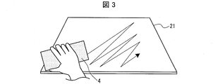
- the eraser device 4 is an input device for the user to perform an erasing operation on the touch panel 2.
- the user performs the erasing operation by holding the eraser device 4 and moving the eraser device 4 while contacting or approaching the panel unit 21.
- the configuration of the eraser device 4 will be described later.
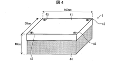
- FIG. 4 is a perspective view showing the appearance of the eraser device 4.
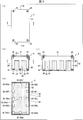
- 5A is a top view of the eraser device 4
- FIG. 5B is a cross-sectional view taken along the line AA shown in FIG. 5A
- FIG. 5C is a cross-sectional view taken along the line B--shown in FIG. It is sectional drawing of B cross section
- (d) is sectional drawing of CC cross section shown in (b).
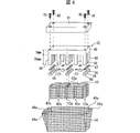
- FIG. 6 is an exploded perspective view of the eraser device 4.
- FIG. 7 is a cross-sectional view of the conductive buffer member 46 provided in the eraser device 4.
- the eraser device 4 includes a grip part 41, a main body part 42, a column protection part 43, a cloth part 44, a screw 45, and a conductive buffer member 46.
- the shape of the eraser device 4 is a substantially rectangular parallelepiped shape having a length of 100 m, a width of 50 mm, and a height of 40 mm.
- the grip portion 41 is made of a conductive member such as metal or conductive resin, and is disposed so as to cover the upper surface of the eraser device 4 and the upper surface side end portions of the side surfaces.
- a plate-like member made of a conductive resin having a thickness of 3 mm is used as the grip portion 41.
- the main body 42 is made of a conductive member such as a metal or a conductive resin, and has a substantially rectangular base 49 and 13 pillars 48 (first to thirteenth pillars) projecting from the base 49 in a predetermined direction. 48a to 48m).
- each column part 48 is directed from the base part 49 toward the bottom surface side (touch panel 2 side) of the eraser device 4, that is, the opposing surface of the grip part 41 and the base part 49 (in the case of FIG. 6).
- the opposing surfaces of the grip portion 41 and the base portion 49 are provided so as to protrude in a direction substantially perpendicular to the flat surface).
- each column unit 48 may be configured to be in a direction substantially perpendicular to the panel unit 21.
- the thickness of the base portion 49 is 5 mm
- the length of the column portion 48 is 30 mm.
- the cross-sectional shape of the column part 48 was made into the square shape of 8 mm per side.
- the eraser device 4 is viewed from the bottom side among the thirteen column portions 48 (the first column portion 48a to the thirteenth column portion 48m).
- the first to fourth column portions 48a to 48d are sometimes arranged at the four corners of the rectangular base 49, and the center of the base 49 (the position corresponding to the intersection of the diagonals of the rectangular shape or the vicinity of the intersection) ),
- the fifth column portion 48e is disposed
- the sixth to eighth column portions 48f to 48h are disposed on one long side of the rectangular shape
- the ninth to eleventh column portions 48i to 48k are disposed on the other long side.
- the twelfth column 481 is arranged on one short side of the rectangular shape
- the thirteenth column 48m is arranged on the other short side.
- the pillar part 48 whose cross-sectional shape is a quadrangle is used, but the shape of the pillar part 48 is not limited to this.
- the cross-sectional shape is a circle, an ellipse, a polygon, or a polygon.
- angular part etc. may be sufficient.
- the number of column portions 48 is not limited to 13 as well.
- a conductive buffer member 46 is attached to a tip of each column portion 48 in the predetermined direction (an end surface on the bottom surface side of the eraser device 4) so as to be electrically connected to the column portion 48 by a conductive adhesive member 47.
- the conductive adhesive member 47 is not particularly limited as long as it is a conductive adhesive member.
- a conductive acrylic pressure-sensitive adhesive or a conductive nonwoven fabric double-sided tape can be used.
- FIG. 7 is a cross-sectional view of the conductive buffer member 46.
- the conductive buffer member 46 has a configuration in which the periphery of the buffer member 46a is covered with a conductive film 46b.
- the configuration of the buffer member 46a is not particularly limited as long as it is a member having moderate elasticity.
- a foam such as polyurethane foam can be used.
- the conductive film 46b is not particularly limited as long as it is conductive and has a flexibility to deform following the deformation of the buffer member 46a.
- a film provided with a conductive material such as nickel or nickel, or a conductive film in which a conductive layer made of copper and nickel is formed on the surface of a resin such as polyimide can be used.
- the column protection part 43 is made of a non-conductive elastic member such as polyurethane, and is disposed so as to fill a gap between the column parts 48 in a region between the column parts 48.
- the column protection part 43 has a notch 43a corresponding to the shape of each column part 48 at a position corresponding to each column part 48, and each notch part 43a corresponds to the notch part 43a.
- the cloth portion 44 is a thin non-conductive cloth-like member such as felt, and is arranged so as to cover the bottom surface of the eraser device 4 and the bottom surface portion of each side surface.
- the cloth portion 44 includes a portion disposed on the bottom surface and side surface of the main body portion 42 in the eraser device 4, and an upper surface of the main body portion 42 from the upper end portion on the side surface of the main body portion 42. And an end portion 44a that is folded along. And since the edge part 44a is pinched
- the thickness of the cloth portion 44 is determined when the user grips the eraser device 4 and brings the bottom surface of the eraser device 4 (the surface on the tip side of each column portion 48) close to or in contact with the panel portion 21 of the touch panel 2.
- the thickness is set such that a change in capacitance due to each column 48 is detected by the touch panel 2.
- the thickness of the cloth portion 44 is 1 mm.
- the screw 45 is made of a conductive material such as metal or conductive resin, and fixes the grip part 41 and the main body part 42 with the end 44a of the cloth part 44 sandwiched between the grip part 41 and the main body part 42. To do. Thereby, the grip part 41, the main-body part 42, the electroconductive buffer member 46, and the user holding the grip part 41 are electrically connected.
- the grip portion 41 and the main body portion 42 are attached by the conductive screw 45, but the present invention is not limited thereto, and for example, by a conductive adhesive member (for example, a conductive adhesive or a conductive double-sided tape). It may be attached. Or you may attach the grip part 41 and the main-body part 42 by engaging the engaging part provided in the grip part 41, and the to-be-engaged part provided in the main-body part 42.
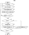
- FIG. 8 is a flowchart showing a flow of processing for detecting an instruction input from the user to the touch panel 2.
- the input point detector 31 receives an input point (by the user) based on a signal indicating the capacitance of each intersection (detection point) between the drive line DL and the sense line SL, which is input from the panel driver 22.
- the touch operation position) is detected (S1).
- the input point detection unit 31 detects, as an input point, an intersection where the capacitance is different from another intersection (or a predetermined reference value) by a predetermined value or more.
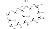
- each column portion 48 of the eraser device 4 is connected to the panel via the conductive buffer member 46 and the cloth portion 44.
- a plurality of detection points (for example, detection points 201 to 213 indicated by crosses in FIG. 9) corresponding to positions in contact with or close to the unit 21 are detected as input points on the touch panel 2.
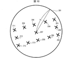
- the region setting unit 34 sets one of the input points detected in S1 as a target input point (S2), and sets a predetermined range region centered on the target input point as the input point search range. (S3).
- the region setting unit 34 has a circle 301 having a radius R1 (radius R1 is 70 mm in this embodiment) centered on the target input point (input point 207 in the example of FIG. 10). Is set as the search range.
- the size of the radius R1 is not limited to 70 mm, and may be set as appropriate according to the size of the eraser device 4, for example. For example, when the radius R1 is the fifth column 48e arranged at the center of the eraser device 4 and the target input point is the radius of the circle including each column 48 (first to thirteenth columns 48a to 48m) May be set.
- the input point counting unit 35 counts the number of input points included in the search range set in S3 (S4). For example, in the example of FIG. 10, 13 input points 201 to 213 are counted.
- the region setting unit 34 determines whether or not there remains an unprocessed input point that has not been subjected to the processing of S2 to S4 with the input point as a target input point among all the input points detected in S1. Determination is made (S5), and if unprocessed input points remain, the process from S2 to S4 is performed with one of the unprocessed input points as a target input point.
- the mode determination unit 36 determines whether or not the user's touch operation is an erasing operation according to the counting result in the process of S4 for each input point. (Whether or not the touch operation is performed by the eraser device 4) is determined (S6). That is, the mode determination unit 36 determines whether the user's touch operation is an erasing operation according to the density of input points.
- the mode determination unit 36 determines that it is an erasing operation when there is an input point of interest in which the number of input points included in the search range is greater than or equal to a threshold (for example, 13), If it does not exist, it is determined that it is not an erasure operation.
- a threshold for example, 13
- the mode determination unit 36 deletes when the number of input points of interest in which the number of input points included in the search range is greater than or equal to the first predetermined number N1 (for example, 3) is greater than or equal to a predetermined threshold (for example, 13). It may be determined that the operation is an operation, and if the number of input points of interest whose number of input points included in the search range is equal to or greater than the first predetermined number N1 is less than the threshold value, it may be determined that the operation is not an erasure operation. .
- the first predetermined number N1 for example, 3
- a predetermined threshold for example, 13
- the erasing range setting unit 37 sets an erasing range based on each input point detected in S1 (S7).
- the X coordinate maximum value, the X coordinate minimum value, the Y coordinate maximum value, and the Y coordinate minimum value are extracted from the coordinates of each input point detected in S1, and specified by these extracted coordinate values.
- Rectangular area [x coordinate minimum value, y coordinate minimum value], [x coordinate minimum value, y coordinate maximum value], [x coordinate maximum value, y coordinate minimum value], [x coordinate maximum value, y coordinate maximum value] (Rectangular area having four corners) is set as an erasure range.
- an area of a rectangle 401 that includes each input point detected in S1 is set as an erasure range.
- the method for setting the erasure range is not limited to this, and for example, a rectangular area formed by a closed curve formed by connecting the input points detected in S1 may be set as the erasure range.
- the width 403 in the X-axis direction of the rectangle 401 is represented by the difference between the maximum X-coordinate value and the minimum X-coordinate value
- the width 404 in the Y-axis direction is represented by the difference between the maximum Y-coordinate value and the minimum Y-coordinate value.
- the coordinates 402 shown in FIG. 11 indicate the center coordinates or barycentric coordinates of the rectangle 401.
- the center coordinates of the rectangle 401 can be obtained by ((X coordinate minimum value + X coordinate maximum value) / 2, (Y coordinate minimum value + Y coordinate maximum value) / 2), and the center-of-gravity coordinate is determined by each input detected in S1. It can be obtained from the average value of the coordinate values of the points.
- the input information output unit 33 After the processing of S7, the input information output unit 33 outputs information indicating the erasing operation and information indicating the erasing range to the information processing apparatus 3 (S8).
- a reference position (for example, center coordinates) of the rectangle 401, a width 403 in the X-axis direction, and a width 404 in the Y-axis direction are output.
- the X coordinate maximum value, the X coordinate minimum value, the Y coordinate maximum value, and the Y coordinate minimum value of the erasing range of the rectangular shape may be output.
- the coordinates of each corner of the rectangular erasure range may be output.
- the shape of the erasure range is a rectangular shape. Thereby, the calculation process of the erasure
- the shape of the erasure range is not limited to this, and for example, it may be set to a circle or an ellipse including each input point detected in S1.
- the input information output unit 33 converts information indicating the erasure range into coordinate values of a coordinate system corresponding to the resolution of the display unit 11 and then performs information processing. You may output to the apparatus 3. Alternatively, the input information output unit 33 outputs information indicating the erasure range to the information processing device 3 with the coordinate value of the coordinate system corresponding to the resolution of the panel unit 21, and the information processing device 3 determines the resolution of the display unit 11 as necessary. You may make it convert into the coordinate system according to.
- the touch panel control unit 23 determines whether or not to end the touch operation detecting process (S10). If not finished, the process returns to S1.
- the method for determining whether or not to end the touch operation detection process is not particularly limited. For example, the determination is made according to whether or not a touch operation end instruction or a power-off instruction is received from the user. Alternatively, it may be determined according to whether or not the touch operation on the touch panel 2 has not been performed for a predetermined time or longer, and a touch-off operation (an operation for moving the eraser device 4 away from the panel unit 21) during the erasing operation. ) May be determined according to whether or not.
- the input information output unit 33 outputs the position information of the input point detected in S1 to the information processing apparatus 3 (S11). At this time, information indicating that the operation is not an erasing operation may be output together with the position information of the input point. Further, when the resolution of the display unit 11 and the resolution of the panel unit 21 are different, the input information output unit 33 converts the position information of the input point into the coordinate value of the coordinate system corresponding to the resolution of the display unit 11 and then performs information processing. You may output to the apparatus 3.
- the input information output unit 33 outputs the position information of the input point to the information processing device 3 with the coordinate value of the coordinate system corresponding to the resolution of the panel unit 21, and the information processing device 3 resolves the resolution of the display unit 11 as necessary. You may make it convert into the coordinate system according to.
- the processes of S2 to S6 are omitted. You may make it perform the process of. Thereby, it is possible to simplify the arithmetic processing when it is not an erasing operation.
- the touch panel control unit 23 determines whether or not to end the touch operation detection process (S10). If not, the touch panel control unit 23 proceeds to the process of S1. Return.
- the eraser device 4 includes a plurality of column portions (touch portions) 48 that are detected as input points when being brought into contact with or in proximity to the panel portion 21 of the touch panel 2.
- a plurality of pillars 48 are formed in the density of the erase operation determination unit 32 of the touch panel 2 to be determined as an erase operation.
- the configuration of the instruction input system 100 can be simplified and the manufacturing cost can be reduced. That is, the instruction input system 100 that can easily perform the erasing operation on the touch panel 2 can be provided at low cost.
- the number of column parts (touch parts) 48 is set to a number (13) larger than the number of fingers of both hands (10), and it is determined whether or not it is an erasing operation.
- the threshold value to be set is set to 13, which is the number of pillars 48.
- the number of pillars 48 installed and the above threshold values are not limited to this.
- the number of pillars 48 is set to a number (11 or more) greater than the number of fingers of both human hands (10 or more), and the threshold value is greater than the number of fingers of both human hands (10).
- the number may be set to be equal to or less than the number of column portions 48.
- the number of pillars 48 is set to a number (6 or more) greater than the number of fingers (5) of one human hand, and the threshold is greater than the number of fingers (5) of one human hand, In addition, the number may be set to be equal to or less than the number of column portions 48. In this case, the touch operation with one human hand and the touch operation with the eraser device 4 can be appropriately distinguished.
- the interval between the column portions 48 is set to an interval at which it is difficult to simultaneously touch and operate input points corresponding to the column portions 48 with a human finger. Thereby, it can suppress more appropriately that touch operation by a person's fingertip is misjudged as erase operation.
- the first to fourth columnar portions 48a to 48d disposed at the corners of the rectangular shape and the fifth columnar portion 48e disposed at the center of the rectangular shape are provided.
- the five pillars 48a to 48e it is difficult for the user to squeeze five fingers and touch the positions corresponding to these five pillars 48a to 48e. The operation and the touch operation by the user's fingertip can be appropriately identified.
- each pillar part 48 it is preferable to set the space
- FIG. Thereby, it can prevent that the some pillar part 48 is erroneously detected as one input point by the touch panel 2.
- FIG. For example, when the interval between the detection points on the touch panel 2 is set to 18 mm, the interval between the column portions 48 is set to an interval sufficiently larger than 18 mm (for example, about 25 mm), thereby a plurality of column portions. 48 can be reliably prevented from being erroneously detected as one input point on the touch panel 2.
- the conductive buffer member 46 is disposed on the end face (end face on the touch panel 2 side) of each column portion 48 in the eraser device 4. Thereby, it can suppress that the dispersion
- the cloth portion 44 is provided so as to cover a part of the surface facing the touch panel 2 and part of the side surface of the eraser device 4.
- the frictional resistance with respect to the touch panel 2 of the eraser apparatus 4 can be reduced, and when the touch panel 2 is slid while being in contact with the touch panel 2, it is possible to suppress the touch panel 2 from being damaged or generating a sound.
- the design of the eraser device 4 can be improved by providing the cloth portion 44.
- the number of column parts (touch parts) 48 is set to a number (13) larger than the number of fingers (10) of both human hands, and a threshold value for determining whether or not the operation is an erasing operation is set. It was set to 13, which is the number of column parts 48.
- the configuration of the eraser device 4 is the same, but the threshold for determining whether or not the erase operation is performed on the touch panel 2 is arranged in the rectangular short-side direction of the eraser device 4. It is set to 3 which is the number of the column parts 48 made. That is, in the present embodiment, the mode determination unit 36 determines that the operation is an erasure operation when there is an input point of interest in which the number of input points included in the search range is 3 or more. Judge that it is not an operation.
- the erase operation can be performed using only a part of the bottom surface of the eraser device 4 (for example, a portion corresponding to one side of the rectangular shape formed by the bottom surface of the eraser device 4).
- An erasing operation can be performed.
- FIG. 12 a case where a touch operation is performed on the panel unit 21 at the rectangular short side portion of the eraser device 4 is considered.
- the three pillars 48 [first pillar part 48a, second pillar part 48b, twelfth pillar part 48l] or [third pillar part 48c, The input points 601, 602, and 603 corresponding to the fourth column part 48d and the thirteenth column part 48m]) are detected.
- the threshold value which determines whether it is erase operation in the touch panel 2 is set to 3, it determines with it being erase operation in the touch panel 2.
- the minimum width of the erase range is set in advance, and when the difference between the X coordinate maximum value and the X coordinate minimum value of the coordinates of each input point is smaller than the minimum width, The width of the erase range in the X-axis direction may be set to the minimum width. Similarly, when the difference between the maximum Y coordinate value and the minimum Y coordinate value among the coordinates of each input point is smaller than the minimum width, the width in the Y-axis direction of the erase range is set to the minimum width. Also good.
- the minimum width is not particularly limited, but may be set to about 5 mm, for example.
- the region setting unit 34 sets a circle 301 having a radius R1 centered on the input point of interest (the input point 207 in the example of FIG. 10) as the search range as shown in FIG. Thereafter, as shown in FIG. 14, the radius R1 is equally divided into N (N is an integer of 2 or more). Then, as shown in FIG. 14, for N areas obtained by equally dividing the radius R1 into N, N is the area closest to the center of the circle 301 (input point 207), and N is the next closest area. ⁇ 1, N-2, etc. are assigned to the next closest area, such as N-2, which gradually decreases as the distance from the center increases. A weighting coefficient 1 is assigned to the farthest area, and a weighting coefficient 0 is assigned to an area farther than the radius R1.
- the input point counting unit 35 assigns a weighting coefficient corresponding to the area to which the input point belongs to each input point, and calculates the total value of the weighting coefficients given to each input point. .
- the processing of S2 to S5 is performed for all the input points, and after calculating the above total value for each input point when each input point is the target input point, in the processing of S6, the mode determination unit 36 It is determined whether or not the user's touch operation is an erasing operation depending on whether or not there is an input point having a value equal to or greater than the first predetermined value V1.
- the subsequent processing is the same as in the first embodiment. Note that whether or not the erasing operation is performed may be determined according to whether or not the number of input points where the calculated total value is equal to or greater than the first predetermined value V1 is equal to or greater than a predetermined threshold.
- the size of the input point search range (circle 301) set in the process of S3 is constant.
- the size of the search range for the input point is set to be larger than the search range (circle 301) before being determined as the erasing operation during the period during which the erasing operation continues.
- the radius of the circle used as the search range for the input point is larger than twice the radius of the initial search range (circle 301) before being determined as the erasure operation.
- the threshold value for determining whether or not the erasing operation is performed in S6 may be set to a value (for example, 1) smaller than the initial threshold value.
- FIG. 15 is an explanatory diagram showing the concept of the erase range setting method in the present embodiment.
- a movement vector (see the arrow in the figure) of each detected input point is calculated for each predetermined time, and each input point whose movement vector is within a predetermined deviation is calculated. (Refer to input points surrounded by broken lines in the figure) is handled as one object, and an area including these input points is set as an erasure range.
- FIG. 16 is a flowchart showing a flow of detection processing of an instruction input from the user in the present embodiment.
- the input point detection unit 31 inputs an input point (touch operation position) based on a signal that is input from the panel drive unit 22 and indicates a capacitance at each intersection (detection point) between the drive line DL and the sense line SL. Detection is started every predetermined period (for example, 5 milliseconds) (S21). The detection result of the input point is temporarily stored in a storage unit (not shown).
- the mode determination unit 36 monitors whether a predetermined time (for example, 0.1 second) has elapsed since the input point detection process was started (or when the movement vector was previously calculated) (S22). If it is determined that a movement vector has been determined, a movement vector (movement vector from the coordinates of each input point before the lapse of a predetermined time to the coordinates of each input point after the lapse of the predetermined time) is calculated (S23).
- a predetermined time for example, 0.1 second
- the mode determination unit 36 determines whether the input points where the deviation of the movement vector is within a predetermined range (for example, within ⁇ 3 mm for each of the x direction and the y direction) are greater than or equal to the second predetermined number N2 (for example, 2 or more). It is determined whether or not (S24). If it is determined in S24 that the second predetermined number N2 is greater than or equal to the second predetermined number N2, the mode determination unit 36 determines that the operation is an erasing operation.
- a predetermined range for example, within ⁇ 3 mm for each of the x direction and the y direction
- the erasure range setting unit 37 determines that the movement vector deviation is within the predetermined range. Are integrated (grouped) (S25).
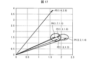
- FIG. 17 is an explanatory diagram for explaining processing for determining whether or not to perform an erasing operation and processing for setting an erasing range.
- the mode determination unit 36 first sorts (searches) the x-coordinates and extracts a group of input points that fall within a deviation of 0.3 mm. As a result, in the example of FIG. 17, the “P1, P3” group and the “P2, P3, P4, P5” group are extracted.
- the mode determination unit 36 sorts the y-coordinates for each of the groups extracted based on the x-coordinates, and extracts a group of input points that are within a deviation of 0.3 mm as in the case of the x-coordinates.
- a group (group 1) of “P1, P3” and a group (group 2) of “P2, P3, P4” are extracted.
- the mode determination unit 36 compares the number of input points included in each group for each group extracted based on the x coordinate and the y coordinate, and extracts a group having a large number of input points.
- group 2 having a large number of input points is extracted from groups 1 and 2.
- the mode determination unit 36 determines whether or not the number of input points included in the extracted group (group 2 in the example of FIG. 17) is equal to or greater than the second predetermined number N2, and is greater than or equal to the second predetermined number N2.
- the erasure range setting unit 37 integrates the input points included in the group.
- the mode determination unit 36 calculates the movement vector of the group based on the average value of the input points included in the group, and as one object It may be handled.
- the newly added input point is compared with the movement vector of the existing input point (or the movement vector of the integrated group), and a new input is made. You may make it determine whether it adds to the group which integrated the point.
- the erasure range setting unit 37 After integrating the input points whose movement vector deviation is within the predetermined range in S25, the erasure range setting unit 37 sets the erasure range based on the integrated input points (S26).
- the erasure range setting unit 37 extracts the X coordinate maximum value, the X coordinate minimum value, the Y coordinate maximum value, and the Y coordinate minimum value from the coordinates of the input points integrated in S25, and extracts these values.
- a rectangular area specified by the coordinate value of is set as an erasure range.
- the input information output unit 33 outputs information indicating the erasing operation and information indicating the erasing range to the information processing apparatus 3 (S27).
- a reference position (for example, center coordinates) of the rectangle 501, a width 503 in the X-axis direction, and a width 504 in the Y-axis direction are output.
- the X coordinate maximum value, the X coordinate minimum value, the Y coordinate maximum value, and the Y coordinate minimum value of the erasing range of the rectangular shape may be output.
- the coordinates of each corner of the rectangular erasure range may be output.
- the touch panel control unit 23 determines whether or not to terminate the touch operation detection process (S29), and if not, returns to the process of S22.
- the method for determining whether or not to end the touch operation detection process is not particularly limited. For example, the determination is made according to whether or not a touch operation end instruction or a power-off instruction is received from the user. It may be determined that the touch operation on the touch panel 2 is not performed (when touched up), and the touch operation on the touch panel 2 is not performed for a predetermined time or longer. Judgment may be made depending on whether or not it has been done.
- the input information output unit 33 detects each input point detected at each predetermined cycle. Is output to the information processing apparatus 3 (S28), and the process proceeds to S29.
- the movement vector of each input point is calculated every predetermined time, and an area including each input point within which the calculated movement vector is within a predetermined deviation is set as an image erasing range. To do.
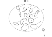
- FIG. 18 is an explanatory diagram showing the concept of the erase range setting method in the present embodiment. As shown in this figure, in this embodiment, for each detected input point, a change in the distance between adjacent input points within a predetermined period is calculated, and each input point whose distance change amount is within a predetermined value is calculated. Treated as one object, and an area including these input points is set as an erasure range.
- FIG. 19 is a flowchart showing a flow of detection processing of an instruction input from the user in the present embodiment.
- the input point detection unit 31 is input from the panel drive unit 22 based on a signal indicating the capacitance at each intersection (detection point) between the drive line DL and the sense line SL (for example, every predetermined period (for example, An input point (touch operation position) is detected every 5 milliseconds (S31).
- the detection results of the input points are sequentially stored in a storage unit (not shown).
- the mode determination unit 36 calculates the distance between adjacent input points (see arrows in FIG. 18) for each input point detected this time in S31 (S32).
- the distance calculation results are sequentially stored in a storage unit (not shown).
- the mode determination unit 36 excludes an input point whose distance from an adjacent input point is equal to or greater than a predetermined determination value (for example, 15 cm) from the determination process of whether or not it is an erasing operation (S33).
- a predetermined determination value for example, 15 cm
- the mode determination unit 36 determines whether or not a predetermined period (for example, 50 milliseconds) has elapsed since the detection of the input point was started (S34). If it is determined that the predetermined period has not elapsed, the process returns to S31.
- a predetermined period for example, 50 milliseconds
- the mode determination unit 36 determines that the input point whose distance variation between adjacent input points within the predetermined period is equal to or smaller than a second predetermined value V2 (for example, 2 mm) is the third. It is determined whether or not there is a predetermined number N3 (for example, two) or more (S35). If it is determined in S35 that the number is greater than or equal to the third predetermined number N3, the mode determination unit 36 determines that the operation is an erasing operation. If it is determined that the operation is less than the third predetermined number N3, the mode determination unit 36 determines that the operation is not an erasing operation. To do.
- a predetermined number N3 for example, two
- S35 the mode determination unit 36 determines that the operation is an erasing operation. If it is determined that the operation is less than the third predetermined number N3, the mode determination unit 36 determines that the operation is not an erasing operation.
- the erasure range setting unit 37 determines each input whose variation range of the distance from the adjacent input point is equal to or smaller than the second predetermined value V2.
- the points are integrated (grouped) (S36).
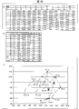
- FIG. 20A and 20B are explanatory diagrams for explaining a determination process for determining whether or not an erasing operation is performed and an erasing range setting process.
- FIG. 20A is a coordinate detection value for each predetermined period of each input point
- FIG. The distance between adjacent input points for each time, (c) shows the erase range set based on each input point.
- the mode determination unit 36 determines whether there is an input point whose distance from an adjacent input point is equal to or greater than a predetermined determination value (for example, 15 cm) every predetermined cycle, and deletes the input point if it exists. Exclude from operation judgment processing.
- a predetermined determination value for example, 15 cm
- the mode determination unit 36 sorts (searches) each input point based on the x coordinate value.
- P3, P1, P5, P2, P6, and P4 are in order from the smallest x coordinate value. Since the difference between the x-coordinate values of the input point P3 having the smallest x-coordinate value and the input point P4 having the largest x-coordinate value does not exceed the predetermined determination value (15 cm), nothing is excluded from the determination process of the erasing operation.
- P2, P4, P1, P3, P6 and P5 are in ascending order of y-coordinate value, and there is no input point where the difference in y-coordinate value exceeds a predetermined determination value (15 cm). Therefore, nothing is excluded from the determination process of the erasing operation.
- the mode determination unit 36 determines the distance between adjacent input points (distance between P3-P1, P1-P5, P5-P2, P2-P6, P6-P4 from the result of sorting based on the x-coordinate values. ) Is calculated. The calculation of the distance between the adjacent input points is continued from time t1 to time t10, during which the fluctuation range of the calculated distance (difference between the minimum value min and the maximum value max) ⁇ max is a second predetermined value V2 (for example, 2 mm). ) If there is an input point that exceeds the above, exclude the input point from the integration target and perform recalculation. Thereby, in the example of FIG. 20, the input point P2 is excluded.
- the erasure range setting unit 37 integrates the input points whose distance fluctuation range is equal to or less than a predetermined value (S36).
- a predetermined value S36
- a group having a large number of input points is selected and integrated.
- the erasure range setting unit 37 sets an erasure range based on the coordinates of the integrated input points (S37). Specifically, the X coordinate maximum value, the X coordinate minimum value, the Y coordinate maximum value, and the Y coordinate minimum value are extracted from the coordinates of the integrated input points, and the rectangular area specified by these extracted coordinate values Set to the erase range.
- the input information output unit 33 outputs information indicating the erasing operation and information indicating the erasing range to the information processing apparatus 3 (S38).
- the touch panel control unit 23 determines whether or not to end the touch operation detection process (S40), and if not, returns to the process of S31.
- the input information output unit 33 Outputs the position information of the input point detected in S31 to the information processing apparatus 3 (S39), and proceeds to the process of S40.
- the area at the initial setting of the erasure range is calculated based on the coordinate values of each integrated input point detected every predetermined period, and the integrated input points
- the area of the rectangular area specified by the X coordinate maximum value, the X coordinate minimum value, the Y coordinate maximum value, and the Y coordinate minimum value is continuously monitored, and the area is compared with the area at the time of initial setting of the erase range.
- the input point integration processing and the erasure range setting processing may be performed again when the ratio changes by a predetermined ratio or more. Thereby, even if the input points to be integrated are increased or decreased after the erasure range is set, the erasure range can be appropriately set according to the touch operation.
- the input point P3 is gradually separated from the other input points, and the area of the rectangular area A gradually increases from the rectangular area A (t0) at time t0 to the rectangular area A (t10) at time t10. It gets bigger.
- at least one of the difference between the maximum value and the minimum value of the x coordinate of the integrated input point and the difference between the maximum value and the minimum value of the y coordinate is a predetermined value (for example, 5 mm) or more than at the time t0.
- the input points to be integrated are recalculated when they become large, and the input point P3 is excluded from the integration targets.
- the excluded input point P3 may be used as an input point for a drawing operation instead of an input point for an erasing operation.
- an area including each input point in which the amount of change in the distance between the input points within a predetermined period is within a predetermined value is set as the erasure range.
- input points to be included in the erasure range can be determined according to a change in distance between input points for a predetermined period. For this reason, for example, even when an input operation by a device other than the eraser device 4 is performed near the area touched by the eraser device 4, an erasing operation and an operation other than the erasing operation are appropriately identified, and erroneous determination occurs. Can be prevented. Further, even when the touch area by the eraser device 4 moves in a curved line instead of a linear movement, input points to be integrated can be detected appropriately.
- the input point integration method according to the sixth embodiment described above (a method of integrating each input point whose movement vectors for each predetermined time of the detected input points are within a predetermined deviation);
- the integration method according to the seventh embodiment (a method of integrating each input point in which the fluctuation range of the distance between adjacent input points within a predetermined period for each detected input point is within the second predetermined value V2).
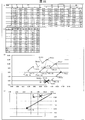
- FIG. 22 is an explanatory diagram for explaining a determination process for determining whether or not to perform an erasing operation and an erasing range setting process, in which (a) is a coordinate detection value at each predetermined period of each input point, and (b) is a predetermined period. The distance between adjacent input points for each, (c) shows the detected coordinates of each input point, and (d) shows the movement vector of each input point.
- the input point detection unit 31 detects an input point every predetermined cycle (5 milliseconds in the present embodiment). Then, the area setting unit 34 calculates the movement vector of each input point every predetermined time (in this embodiment, 30 milliseconds, which is the period from t1 to t7), and the mode determination unit 36 sets the deviation of the movement vector within a predetermined range.
- An input point that is outside (for example, outside the range of ⁇ 3 mm in each of the x direction and the y direction) is excluded from the integration processing targets. Accordingly, in the example of FIG. 17, since the movement vector of the input point P2 is outside the predetermined range as shown in (a), the input point at time t7 as shown in (c) and (d). P2 is excluded from the target of integration processing.
- the mode determination unit 36 determines that the operation is not an erasure operation when the input point where the deviation of the movement vector is within a predetermined range is less than a second predetermined number N2 (for example, two).
- the mode determination unit 36 has a predetermined period (in this embodiment, 50 milliseconds, which is the period from t1 to t10). Every time elapses, a change in distance between adjacent input points within the predetermined period is calculated.
- the mode determination unit 36 determines that it is not an erasing operation when the input point whose fluctuation range is equal to or smaller than a second predetermined value V2 (for example, 2 mm) is less than a third predetermined number N3 (for example, two).
- the mode determining unit 36 determines that the erasing operation is performed.
- the erasure range setting unit 37 sets an area including each input point whose distance fluctuation range is within the second predetermined value V2 as the erasure range.
- the narrowed input points after narrowing down the input points to be subjected to the integration process based on the deviation of the movement vector for each input point, the narrowed input points based on the change in the distance between the input points. It is determined whether or not to integrate each input point.
- an input point integration method (a method of integrating input points whose movement vectors for each predetermined time of detected input points are within a predetermined deviation) is according to the seventh embodiment. While the calculation is simpler than the integration method (the method of integrating the input points in which the fluctuation range of the distance between adjacent input points within the predetermined period for each detected input point is within the second predetermined value V2), The accuracy of erasure range setting is higher in the integration method according to the seventh embodiment. Therefore, according to the method of the present embodiment, the advantages of both the input point integration method according to the sixth embodiment and the integration method according to the seventh embodiment can be utilized, and the erasure range can be accurately set by simple calculation. It can be carried out.
- the input points are narrowed down by the input point integration method according to the sixth embodiment (a method in which input points whose movement vectors of the detected input points per predetermined time are within a predetermined deviation) are integrated. After that, the distance between the input points may be calculated, and the input points whose calculated distance is greater than or equal to a predetermined determination value may be excluded from the integration process at that time.
- the input point by the sleeve and the input point by the eraser device 4 are Since the distance is longer than the distance between the pillars 48 in the eraser device 4, the input point by the sleeve or the like can be excluded from the target of the integration process. Therefore, it is possible to prevent the image from being erased against the user's intention due to the sleeve or the like coming into contact with the panel portion 21.
- the touch panel control unit 23 of the touch panel 2 may be realized by a logic circuit (hardware) formed in an integrated circuit (IC chip) or the like, or software using a CPU (Central Processing Unit). It may be realized by.
- the touch panel control unit 23 includes a CPU that executes instructions of a program that is software for realizing each function, and a ROM (Read Only Memory) in which the program and various data are recorded so as to be readable by the computer (or CPU).
- a storage device (these are referred to as “recording media”), a RAM (Random Access Memory) for expanding the program, and the like are provided.
- the objective of this invention is achieved when a computer (or CPU) reads the said program from the said recording medium and runs it.
- a “non-temporary tangible medium” such as a tape, a disk, a card, a semiconductor memory, a programmable logic circuit, or the like can be used.
- the program may be supplied to the computer via an arbitrary transmission medium (such as a communication network or a broadcast wave) that can transmit the program.
- a transmission medium such as a communication network or a broadcast wave
- the present invention can also be realized in the form of a data signal embedded in a carrier wave in which the program is embodied by electronic transmission.
- the eraser device 4 is an eraser device 4 for inputting a display image erasing operation to the touch panel 2, and the touch panel 2 includes a large number of detection points arranged on the display screen.
- An input point detection unit 31 that detects a touch-operated detection point as an input point
- an erasure operation determination unit 32 that determines whether a user operation is an erasure operation according to the density of the input points.
- the eraser device 4 includes a plurality of touch portions (column portions 48) that are detected as the input points when the touch panel 2 is brought into contact with or close to the touch panel 2, and the plurality of touch portions (column portions 48). ) Is formed at the density determined by the erasing operation determination unit 32 as an erasing operation.
- the touch panel 2 by performing touch operation with respect to the touch panel 2 using the eraser apparatus 4, the touch panel 2 is made to detect each touch part (column part 48) of the eraser apparatus 4 as an input point, and each of these input points is detected. It can be determined that the erasing operation is based on the degree of congestion. Therefore, the touch panel 2 can recognize that it is an erasing operation without transmitting information indicating an erasing instruction from the eraser device 4 to the touch panel 2. For this reason, since it is not necessary to provide the eraser device 4 and the touch panel 2 with a communication function, the manufacturing cost of the eraser device 4 and the touch panel 2 can be reduced.
- the touch panel 2 can recognize the erasing operation without performing a mode switching operation for switching between the drawing mode and the eraser mode, the convenience of the user can be improved. Therefore, according to said structure, the instruction
- the eraser device 4 according to aspect 2 of the present invention is the above-described aspect 1, wherein the touch panel 2 is a capacitive touch panel, and the eraser device 4 is gripped by the plurality of touch parts (column parts 48) and a user.
- the touch part (column part 48) and the grip part 41 are both electrically conductive, and the touch part (column part 48) and the grip part 41 are electrically connected to each other. This is a conductive configuration.
- each touch part (column part 48) with which the eraser apparatus 4 is equipped can be grounded by electrically connecting with the user holding the said eraser apparatus 4, each touch part The detection accuracy of (column part 48) can be improved.
- the eraser device 4 according to aspect 3 of the present invention is the eraser device 4 according to aspect 2, in which each of the touch portions (column portions 48) includes a conductive column portion 48 protruding in a predetermined direction, and the column portion 48 in the predetermined direction. It is the structure provided with the electroconductive buffer member (conductive buffer member 46) attached so that it might be electrically connected with the said pillar part 48 at the front-end
- each touch part the column part 48 and the conductive buffer member 46
- covering each touch part with the cloth part 44, it can suppress that the touch panel 2 is damaged by making the eraser apparatus 4 contact the touch panel 2, or a sound is produced.
- the eraser device 4 according to the aspect 4 of the present invention has the configuration in the aspect 3 in which the column protection part 43 made of a non-conductive elastic member is disposed in the region between the column parts.
- the eraser apparatus 4 when the eraser apparatus 4 is made to contact the touch panel 2, the load which acts on each pillar part is reduced by the pillar protection part 43 which consists of a nonelectroconductive elastic member, and each pillar part is damaged. Can be prevented.
- the eraser device 4 according to the fifth aspect of the present invention is the eraser device 4 according to any one of the first to fourth aspects, wherein the first to fourth touch portions (first column portions 48a to 48th) of the plurality of touch portions (column portions 48). All of the plurality of touch portions (the first column portion 48a to the thirteenth column portion 48m) are arranged in a rectangular region having four corners of the four column portions 48d), and the plurality of touch portions (the first column portions 48a to 48m) are arranged. Among the thirteenth column portion 48m), the plurality of touch portions (first column portion 48a to thirteenth column portion 48m) are arranged such that the fifth touch portion (fifth column portion 48e) is arranged at the center of the rectangular region. ) Of each position is determined.
- the erasure range can be easily specified based on the detection position of the input point corresponding to each touch part (the first pillar part 48a to the thirteenth pillar part 48m). Also, compared to the case where the touch portions (first column portion 48a to fourth column portion 48d) are provided only at the corners of the rectangular shape, the degree of density of the touch portions (first column portion 48a to thirteenth column portion 48m) is increased. Therefore, the touch operation by the eraser device 4 and the touch operation by a human finger or pen can be easily identified.
- the instruction input system 100 includes an input point detection unit 31 that detects, as an input point, a detection point that is touch-operated among a large number of detection points arranged on a display screen, and the input points are densely arranged.
- a touch panel 2 having an erasing operation determination unit 32 that determines whether or not the user's operation is an erasing operation according to the degree, and the eraser device 4 according to any one of the above aspects 1 to 5 are provided. It is said.
- the touch panel 2 by performing a touch operation on the touch panel 2 with the eraser device 4, the touch panel 2 detects each touch portion (column portion 48) of the eraser device 4 as an input point, and an erase operation is performed according to the degree of congestion. It can be determined that there is. Therefore, the touch panel 2 can recognize that it is an erasing operation without transmitting information indicating an erasing instruction from the eraser device 4 to the touch panel 2. For this reason, since it is not necessary to provide the eraser device 4 and the touch panel 2 with a communication function, the manufacturing cost of the eraser device 4 and the touch panel 2 can be reduced.
- the touch panel 2 can recognize the erasing operation without performing a mode switching operation for switching between the drawing mode and the eraser mode, the convenience of the user can be improved. That is, according to said structure, the instruction input system 100 which can perform the erasing operation with respect to the touch panel 2 easily can be provided at low cost.
- the distance between the touch portions (column portions 48) is determined by the input point detection unit 31 so that each touch portion (column portion 48) is input separately. It is the structure set to the space
- each touch part (column part 48) can be detected as a separate input point, the density of the input points can be appropriately evaluated.
- the erasure operation determination unit 32 sequentially selects the input points detected by the input point detection unit 31 one by one as the target input points. Then, a region setting unit 34 for setting a region in a predetermined range centered on the selected target input point as a search range for the target input point, and counting the number of input points existing in the search range for each target input point And when the number of input points of interest whose number counted by the input point counting unit 35 is equal to or greater than a first predetermined number N1 is greater than or equal to a predetermined threshold, It is the structure provided with the mode determination part 36 determined to exist.
- the erase operation is determined. Thereby, it can be appropriately determined whether or not the user's operation is an erasing operation according to the density of the input points.
- the input point detecting unit 31 performs the operation. Of the detected input points, an image erasing process is performed on an area including each input point included in the integrated determination range of a predetermined size with the input point having the maximum value counted by the input point counting unit 35 as a reference position.
- the erasure range setting unit 37 is set as an erasure range that is the target range of the image.
- the range corresponding to the user's touch operation can be set as the erase range by setting the erase range according to the input points included in the integrated determination range.
- the instruction input system 100 according to the tenth aspect of the present invention is the instruction input system 100 according to the sixth or seventh aspect, wherein the erasing operation determination unit 32 sequentially selects the input points detected by the input point detection unit 31 one by one as the target input points.
- a region setting unit 34 that sets a region within a predetermined range centered on the selected target input point as a search range for the target input point, and the input point and the target for each input point existing in the search range
- An input point counting unit 35 that assigns a weighting coefficient that becomes smaller as the distance to the input point becomes longer, counts the total value of the weighting coefficients assigned for each input point for each input point of interest, and the input point counting unit 35
- a mode in which the user's operation is determined to be the erasing operation when the number of input points of interest whose total number counted is equal to or greater than a first predetermined value V1 is equal to or greater than a predetermined threshold. It is configured to have a tough 36.
- a weighting coefficient that decreases as the distance from the input point to the other input point increases with respect to another input point existing within a predetermined range with respect to the input point.
- the erasing operation determination unit 32 determines that the erasing operation is performed by the mode determination unit 36
- the input point detection unit 31 Among the detected input points, an area including each input point included in the integrated determination range having a predetermined size with the input point having the maximum total value counted by the input point counting unit 35 as a reference position is erased.
- an erasure range setting unit 37 is set as an erasure range that is a processing target range.
- the range corresponding to the user's touch operation can be set as the erase range by setting the erase range according to the input points included in the integrated determination range.
- the input points to be included in the erasure range are selected based on the result weighted according to the distance between the input points, the input points may fluctuate due to changes in the degree of contact with the display screen during the user's touch operation. Even if it occurs, the erasure range can be set appropriately.
- the erasing operation determination unit 32 calculates the input points detected by the input point detection unit 31 at predetermined time intervals.
- a mode determining unit that determines that the user's operation is an erasing operation when there are more than a second predetermined number N2 of input points whose movement vectors for each input point are within a predetermined deviation; and the mode determining unit
- an erasure range setting for setting an area including each of the input points whose movement vector is within a predetermined deviation as an erasure range that is an object erasure process range. And a portion 37.
- input points to be included in the erasure range can be determined according to how the input points (touch points touched by the user) move. For this reason, for example, even when an input operation (such as a drawing operation) that is different from the erase operation is performed near the erase range, the erase operation and an operation other than the erase operation are appropriately identified to prevent erroneous determination. it can.
- the erasing operation determination unit 32 is a distance between input points among a plurality of input points detected by the input point detection unit 31.
- a mode determination unit 36 that determines that the user's operation is an erasure operation when there are at least a third predetermined number N3 of input points whose fluctuation range is within a predetermined value within the predetermined period, and the mode determination unit 36 erases the input point
- an area including each input point whose fluctuation range within a predetermined period of the distance between the input points is within a second predetermined value V2 is an erasing process target range of the image.
- This configuration includes an erasing range setting unit 37 that sets the range.
- input points to be included in the erasure range can be determined according to how the input points (touch points touched by the user) move. For this reason, for example, even when an input operation (such as a drawing operation) that is different from the erase operation is performed near the erase range, the erase operation and an operation other than the erase operation are appropriately identified to prevent erroneous determination. it can.
- the erasing operation determination unit 32 calculates the input points detected by the input point detection unit 31 at predetermined time intervals. There are at least a second predetermined number N2 of input points whose movement vectors for each input point are within a predetermined deviation, and the fluctuation range of the distance between the input points within a predetermined period is within the second predetermined value V2.
- the mode determining unit 36 that determines that the user's operation is an erasing operation when the input point is greater than or equal to the third predetermined number N3, and the movement when the erasing operation determining unit 32 determines that the erasing operation is an erasing operation.
- An area including each input point in which a vector is within a predetermined deviation and a fluctuation range of the distance between the input points within a predetermined period is within a second predetermined value V2 is a pair of image erasing processes.
- input points to be included in the erasure range can be determined according to how the input points (touch points touched by the user) move. For this reason, for example, even when an input operation (such as a drawing operation) that is different from the erase operation is performed near the erase range, the erase operation and an operation other than the erase operation are appropriately identified to prevent erroneous determination. it can.
- the present invention can be used for a touch panel.
Landscapes
- Engineering & Computer Science (AREA)
- General Engineering & Computer Science (AREA)
- Theoretical Computer Science (AREA)
- Human Computer Interaction (AREA)
- Physics & Mathematics (AREA)
- General Physics & Mathematics (AREA)
- Position Input By Displaying (AREA)
- User Interface Of Digital Computer (AREA)
Priority Applications (2)
| Application Number | Priority Date | Filing Date | Title |
|---|---|---|---|
| CN201580080864.1A CN107710109B (zh) | 2015-06-12 | 2015-10-06 | 输入装置和指示输入系统 |
| US15/735,302 US10466850B2 (en) | 2015-06-12 | 2015-10-06 | Eraser device and command input system |
Applications Claiming Priority (2)
| Application Number | Priority Date | Filing Date | Title |
|---|---|---|---|
| JP2015-119596 | 2015-06-12 | ||
| JP2015119596A JP6546455B2 (ja) | 2015-06-12 | 2015-06-12 | イレーサ装置および指示入力システム |
Publications (1)
| Publication Number | Publication Date |
|---|---|
| WO2016199320A1 true WO2016199320A1 (ja) | 2016-12-15 |
Family
ID=57503753
Family Applications (1)
| Application Number | Title | Priority Date | Filing Date |
|---|---|---|---|
| PCT/JP2015/078405 WO2016199320A1 (ja) | 2015-06-12 | 2015-10-06 | イレーサ装置および指示入力システム |
Country Status (4)
| Country | Link |
|---|---|
| US (1) | US10466850B2 (ko) |
| JP (1) | JP6546455B2 (ko) |
| CN (1) | CN107710109B (ko) |
| WO (1) | WO2016199320A1 (ko) |
Families Citing this family (4)
| Publication number | Priority date | Publication date | Assignee | Title |
|---|---|---|---|---|
| TWI694374B (zh) * | 2018-08-30 | 2020-05-21 | 禾瑞亞科技股份有限公司 | 電子拭除裝置 |
| WO2020095710A1 (ja) * | 2018-11-09 | 2020-05-14 | 株式会社ワコム | 電子消去具及び筆記情報処理システム |
| US20200371680A1 (en) * | 2019-05-20 | 2020-11-26 | Microsoft Technology Licensing, Llc | Method and system for touch screen erasing |
| JP7482706B2 (ja) * | 2020-07-08 | 2024-05-14 | 株式会社ワコム | スタイラス及びセンサコントローラによって実行される方法、スタイラス、及びセンサコントローラ |
Citations (4)
| Publication number | Priority date | Publication date | Assignee | Title |
|---|---|---|---|---|
| JP2011134298A (ja) * | 2009-11-30 | 2011-07-07 | Takashi Yamamoto | 情報処理装置用の駆動装置及びマルチタッチ機能を利用した情報処理システム |
| JP2012099093A (ja) * | 2010-10-08 | 2012-05-24 | Ag Ltd | タッチパッド用の入力デバイス、プログラム、データ処理方法およびデータ処理装置 |
| JP2013012057A (ja) * | 2011-06-29 | 2013-01-17 | Panasonic Corp | 認証鍵及び認証装置 |
| WO2014147880A1 (ja) * | 2013-03-19 | 2014-09-25 | 株式会社ビーツーエンジン | タッチパネル用操作器具 |
Family Cites Families (65)
| Publication number | Priority date | Publication date | Assignee | Title |
|---|---|---|---|---|
| US5475401A (en) * | 1993-04-29 | 1995-12-12 | International Business Machines, Inc. | Architecture and method for communication of writing and erasing signals from a remote stylus to a digitizing display |
| JPH08263212A (ja) * | 1995-03-27 | 1996-10-11 | Canon Inc | 座標入力装置及び該装置を用いた情報処理装置 |
| US5793360A (en) * | 1995-05-05 | 1998-08-11 | Wacom Co., Ltd. | Digitizer eraser system and method |
| US6362440B1 (en) * | 1998-03-27 | 2002-03-26 | International Business Machines Corporation | Flexibly interfaceable portable computing device |
| JP3587435B2 (ja) * | 1998-10-16 | 2004-11-10 | 株式会社タカラ | 表示パネル |
| US6046420A (en) * | 1998-12-17 | 2000-04-04 | Electronics For Imaging, Inc. | Silicon switch |
| US6501463B1 (en) * | 1999-12-10 | 2002-12-31 | Siemens Technology -To-Business Center Llc | Electronic whiteboard system using a tactile foam sensor |
| US6948210B1 (en) * | 2002-09-26 | 2005-09-27 | Chirag Shah | Automated board eraser |
| US7262764B2 (en) * | 2002-10-31 | 2007-08-28 | Microsoft Corporation | Universal computing device for surface applications |
| US20040246236A1 (en) * | 2003-06-02 | 2004-12-09 | Greensteel, Inc. | Remote control for electronic whiteboard |
| US20080143691A1 (en) * | 2005-11-23 | 2008-06-19 | Quiteso Technologies, Llc | Systems and methods for enabling tablet PC/pen to paper space |
| TWI361995B (en) * | 2007-07-03 | 2012-04-11 | Elan Microelectronics Corp | Input device of capacitive touchpad |
| US8243028B2 (en) * | 2008-06-13 | 2012-08-14 | Polyvision Corporation | Eraser assemblies and methods of manufacturing same |
| EP2226704B1 (en) * | 2009-03-02 | 2012-05-16 | Anoto AB | A digital pen |
| KR20120095852A (ko) * | 2009-10-15 | 2012-08-29 | 스마트 테크놀러지스 유엘씨 | 디스플레이 표면상에서 손글씨 잉크 객체를 그리기 및 지우기 하는 방법 및 장치 |
| KR101144724B1 (ko) * | 2009-12-17 | 2012-05-24 | 이성호 | 터치패널의 터치셀 구조 |
| CN201626217U (zh) * | 2010-01-25 | 2010-11-10 | 岳敏 | 多用静电除尘板擦 |
| US20120028227A1 (en) * | 2010-07-27 | 2012-02-02 | Angela Loggins | myWriteRightpen |
| CN201886421U (zh) * | 2010-09-26 | 2011-06-29 | 广东威创视讯科技股份有限公司 | 一种无线板擦装置 |
| US8988398B2 (en) * | 2011-02-11 | 2015-03-24 | Microsoft Corporation | Multi-touch input device with orientation sensing |
| TWI506487B (zh) * | 2011-03-30 | 2015-11-01 | Hon Hai Prec Ind Co Ltd | 觸摸屏及其控制方法 |
| CN102736759B (zh) * | 2011-04-08 | 2017-02-15 | 富泰华工业(深圳)有限公司 | 触摸屏及其控制方法 |
| KR101820410B1 (ko) * | 2011-05-16 | 2018-03-02 | 삼성전자주식회사 | 디지타이저 시스템에서 디지타이저 펜의 지우개 기능을 지원하기 위한 장치 및 방법 |
| US9430140B2 (en) * | 2011-05-23 | 2016-08-30 | Haworth, Inc. | Digital whiteboard collaboration apparatuses, methods and systems |
| US20140055400A1 (en) * | 2011-05-23 | 2014-02-27 | Haworth, Inc. | Digital workspace ergonomics apparatuses, methods and systems |
| US9007302B1 (en) * | 2011-11-11 | 2015-04-14 | Benjamin D. Bandt-Horn | Device and user interface for visualizing, navigating, and manipulating hierarchically structured information on host electronic devices |
| TWI482100B (zh) * | 2011-12-06 | 2015-04-21 | Wistron Corp | 電子系統與軌跡偵測方法 |
| CN103176626B (zh) * | 2011-12-23 | 2017-04-12 | 技嘉科技股份有限公司 | 触控笔 |
| CN103197870B (zh) * | 2012-01-05 | 2017-03-29 | 汉王科技股份有限公司 | 一种移动终端中切换功能状态的方法及装置 |
| US20130201162A1 (en) * | 2012-02-05 | 2013-08-08 | Ian Daniel Cavilia | Multi-purpose pen input device for use with mobile computers |
| US9400592B2 (en) * | 2012-03-26 | 2016-07-26 | Sharp Laboratories Of America, Inc. | Methods, systems and apparatus for digital-marking-surface space and display management |
| JP5787843B2 (ja) * | 2012-08-10 | 2015-09-30 | 株式会社東芝 | 手書き描画装置、方法及びプログラム |
| KR101967727B1 (ko) * | 2012-08-28 | 2019-04-10 | 삼성전자 주식회사 | 터치펜 및 이를 구비하는 휴대단말장치 |
| JP2014203305A (ja) * | 2013-04-05 | 2014-10-27 | 株式会社東芝 | 電子機器、電子機器の制御方法、電子機器の制御プログラム |
| CN104182137B (zh) * | 2013-05-28 | 2017-06-16 | 福建福昕软件开发股份有限公司 | 一种擦除记录板上的电子笔迹的方法 |
| CN104423869A (zh) * | 2013-09-09 | 2015-03-18 | 中兴通讯股份有限公司 | 文本擦除方法及装置 |
| CN103605477A (zh) * | 2013-11-25 | 2014-02-26 | 向火平 | 基于电容屏手写笔迹的手势定位方法及电容屏 |
| CN103606315B (zh) * | 2013-11-28 | 2016-05-18 | 王滨 | 一种触摸屏书画练习方法及其练习装置 |
| US9232409B2 (en) * | 2013-12-12 | 2016-01-05 | Microsoft Technology Licensing, Llc | Binding of an apparatus to a computing device |
| US9671877B2 (en) * | 2014-01-27 | 2017-06-06 | Nvidia Corporation | Stylus tool with deformable tip |
| US20150212600A1 (en) * | 2014-01-27 | 2015-07-30 | Nvidia Corporation | Stylus tool with deformable tip |
| US10146424B2 (en) * | 2014-02-28 | 2018-12-04 | Dell Products, Lp | Display of objects on a touch screen and their selection |
| JP6058866B2 (ja) * | 2014-06-30 | 2017-01-11 | シャープ株式会社 | タッチパネルコントローラ、スタイラスペン、タッチパネルシステム、および電子機器 |
| US20160041635A1 (en) * | 2014-08-08 | 2016-02-11 | Kabushiki Kaisha Toshiba | Active stylus pen, electronic device and data input system |
| US20160098142A1 (en) * | 2014-10-07 | 2016-04-07 | Microsoft Technology Licensing, Llc | Palm gesture detection |
| JP6564249B2 (ja) * | 2015-01-09 | 2019-08-21 | シャープ株式会社 | タッチパネルおよび操作判定方法 |
| US10698504B2 (en) * | 2015-06-15 | 2020-06-30 | Microsoft Technology Licensing, Llc | Detecting input pressure on a stylus pen |
| IN2015CH03991A (ko) * | 2015-07-31 | 2015-08-14 | Wipro Ltd | |
| WO2017022966A1 (en) * | 2015-08-05 | 2017-02-09 | Samsung Electronics Co., Ltd. | Electric white board and control method thereof |
| TWM522406U (zh) * | 2015-09-18 | 2016-05-21 | 翰碩電子股份有限公司 | 無線觸控筆 |
| JP6620494B2 (ja) * | 2015-09-30 | 2019-12-18 | 株式会社リコー | 通信システム、情報処理装置、通信方法、プログラム |
| EP3358449A4 (en) * | 2015-09-30 | 2018-09-12 | Ricoh Company, Ltd. | Electronic blackboard, recording medium, and information display method |
| TWI571775B (zh) * | 2015-12-01 | 2017-02-21 | Egalax_Empia Tech Inc | Electronic erasure device |
| EP3400532A4 (en) * | 2016-01-05 | 2019-06-26 | Quirklogic, Inc. | PROCESS FOR THE REPLACEMENT OF VISUAL ELEMENTS AND FOR FILLING INDIVIDUAL ASSOCIATED DISPLAYS WITH INTERACTIVE CONTENT |
| US10067731B2 (en) * | 2016-01-05 | 2018-09-04 | Quirklogic, Inc. | Method and system for representing a shared digital virtual “absolute” canvas |
| US20180046345A1 (en) * | 2016-01-05 | 2018-02-15 | Quirklogic, Inc. | Method and system for erasing an enclosed area on an interactive display |
| US10129335B2 (en) * | 2016-01-05 | 2018-11-13 | Quirklogic, Inc. | Method and system for dynamic group creation in a collaboration framework |
| US20180074775A1 (en) * | 2016-06-06 | 2018-03-15 | Quirklogic, Inc. | Method and system for restoring an action between multiple devices |
| US10198177B2 (en) * | 2016-07-14 | 2019-02-05 | Ricoh Company, Ltd. | Image processing apparatus, image processing method, and recording medium |
| US10534449B2 (en) * | 2016-08-19 | 2020-01-14 | Microsoft Technology Licensing, Llc | Adjustable digital eraser |
| US10162518B2 (en) * | 2017-02-03 | 2018-12-25 | Microsoft Technology Licensing, Llc | Reversible digital ink for inking application user interfaces |
| WO2018174786A1 (en) * | 2017-03-22 | 2018-09-27 | Flatfrog Laboratories | Pen differentiation for touch displays |
| US10429954B2 (en) * | 2017-05-31 | 2019-10-01 | Microsoft Technology Licensing, Llc | Multi-stroke smart ink gesture language |
| US10430924B2 (en) * | 2017-06-30 | 2019-10-01 | Quirklogic, Inc. | Resizable, open editable thumbnails in a computing device |
| JP6902423B2 (ja) * | 2017-07-31 | 2021-07-14 | シャープ株式会社 | 筆記入力システム、ボードおよび識別子 |
-
2015
- 2015-06-12 JP JP2015119596A patent/JP6546455B2/ja active Active
- 2015-10-06 WO PCT/JP2015/078405 patent/WO2016199320A1/ja active Application Filing
- 2015-10-06 US US15/735,302 patent/US10466850B2/en active Active
- 2015-10-06 CN CN201580080864.1A patent/CN107710109B/zh active Active
Patent Citations (4)
| Publication number | Priority date | Publication date | Assignee | Title |
|---|---|---|---|---|
| JP2011134298A (ja) * | 2009-11-30 | 2011-07-07 | Takashi Yamamoto | 情報処理装置用の駆動装置及びマルチタッチ機能を利用した情報処理システム |
| JP2012099093A (ja) * | 2010-10-08 | 2012-05-24 | Ag Ltd | タッチパッド用の入力デバイス、プログラム、データ処理方法およびデータ処理装置 |
| JP2013012057A (ja) * | 2011-06-29 | 2013-01-17 | Panasonic Corp | 認証鍵及び認証装置 |
| WO2014147880A1 (ja) * | 2013-03-19 | 2014-09-25 | 株式会社ビーツーエンジン | タッチパネル用操作器具 |
Also Published As
| Publication number | Publication date |
|---|---|
| CN107710109B (zh) | 2021-04-09 |
| JP2017004381A (ja) | 2017-01-05 |
| JP6546455B2 (ja) | 2019-07-17 |
| CN107710109A (zh) | 2018-02-16 |
| US20180181231A1 (en) | 2018-06-28 |
| US10466850B2 (en) | 2019-11-05 |
Similar Documents
| Publication | Publication Date | Title |
|---|---|---|
| US11449224B2 (en) | Selective rejection of touch contacts in an edge region of a touch surface | |
| US9454255B2 (en) | Device and method for localized force sensing | |
| KR102450301B1 (ko) | 중간 차폐 전극층을 채용한 포스 및 근접 센싱을 위한 디바이스 및 방법 | |
| CN107231814B (zh) | 检测错误边界触摸输入的方法和设备 | |
| US20130154938A1 (en) | Combined touchpad and keypad using force input | |
| US9405383B2 (en) | Device and method for disambiguating region presses on a capacitive sensing device | |
| JP6564249B2 (ja) | タッチパネルおよび操作判定方法 | |
| WO2016199320A1 (ja) | イレーサ装置および指示入力システム | |
| US10185427B2 (en) | Device and method for localized force sensing | |
| CN109101127B (zh) | 具有浮动接地或薄触摸面板的触摸屏设备中手掌触摸检测 | |
| US20160034092A1 (en) | Stackup for touch and force sensing | |
| US9898130B2 (en) | Grip management | |
| AU2013100574A4 (en) | Interpreting touch contacts on a touch surface | |
| WO2016111062A1 (ja) | タッチパネルおよび操作判定方法 | |
| KR101385018B1 (ko) | 터치 센싱 장치 및 터치 제스쳐 인식 방법 | |
| WO2016178273A1 (ja) | 駆動制御装置、電子機器、駆動制御プログラム、及び駆動制御方法 | |
| AU2017219061A1 (en) | Interpreting touch contacts on a touch surface |
Legal Events
| Date | Code | Title | Description |
|---|---|---|---|
| 121 | Ep: the epo has been informed by wipo that ep was designated in this application |
Ref document number: 15895004 Country of ref document: EP Kind code of ref document: A1 |
|
| WWE | Wipo information: entry into national phase |
Ref document number: 15735302 Country of ref document: US |
|
| NENP | Non-entry into the national phase |
Ref country code: DE |
|
| 122 | Ep: pct application non-entry in european phase |
Ref document number: 15895004 Country of ref document: EP Kind code of ref document: A1 |