WO2016194862A1 - 車両制御装置及び車両制御方法 - Google Patents
車両制御装置及び車両制御方法 Download PDFInfo
- Publication number
- WO2016194862A1 WO2016194862A1 PCT/JP2016/065859 JP2016065859W WO2016194862A1 WO 2016194862 A1 WO2016194862 A1 WO 2016194862A1 JP 2016065859 W JP2016065859 W JP 2016065859W WO 2016194862 A1 WO2016194862 A1 WO 2016194862A1
- Authority
- WO
- WIPO (PCT)
- Prior art keywords
- steering
- vehicle
- unit
- control device
- case
- Prior art date
- Legal status (The legal status is an assumption and is not a legal conclusion. Google has not performed a legal analysis and makes no representation as to the accuracy of the status listed.)
- Ceased
Links
Images


Classifications
-
- B—PERFORMING OPERATIONS; TRANSPORTING
- B62—LAND VEHICLES FOR TRAVELLING OTHERWISE THAN ON RAILS
- B62D—MOTOR VEHICLES; TRAILERS
- B62D6/00—Arrangements for automatically controlling steering depending on driving conditions sensed and responded to, e.g. control circuits
Definitions
- the present disclosure relates to a vehicle control device and a vehicle control method.
- an electric power steering system that detects steering of a driver and assists the steering force with a motor in accordance with the steering torque is generally used.
- vehicles equipped with a function of automatically steering regardless of the driver's intention have been mass-produced, and this function is often realized by electric power steering.
- a vehicle control device that automatically steers when an obstacle is detected in front of the host vehicle may be considered.
- the steering shaft is connected to the steering shaft, so that the steering rotates in conjunction with the steering shaft.
- the driver's hand holding the steering wheel is moved against the intention, which may cause discomfort to the driver.
- This disclosure is intended to provide a vehicle control device and a vehicle control method that are less likely to cause discomfort to the driver.
- a vehicle control device for use in a vehicle including a steering unit that performs steering of the vehicle and a steering that rotates in conjunction with the steering of the vehicle, the vehicle using the steering unit.
- the steering control unit for steering the vehicle and the first case in which the steering control unit steers the vehicle are more effective in steering the vehicle than in the second case in which the vehicle is steered due to steering by the driver of the vehicle.
- a vehicle control device including a limiting unit that limits the rotation of the accompanying steering.
- a steering control unit mounted on a vehicle including a steering unit that steers the vehicle and a steering that rotates in conjunction with the steering of the vehicle uses the steering unit.
- the steering control unit steers the vehicle by steering and the limiting unit mounted on the vehicle, compared to the second case where the vehicle is steered due to steering by the driver of the vehicle,
- a vehicle control method for limiting the rotation of the steering accompanying the steering of the vehicle is provided.
- the steering control unit steers the vehicle
- the steering of the vehicle accompanying the steering of the vehicle is reduced. Rotation can be limited. As a result, the driver's discomfort caused by the driver's hand holding the steering wheel being moved unintentionally can be reduced.
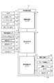
- the drawing It is a block diagram showing the structure of the vehicle control apparatus which concerns on 1st Embodiment, It is explanatory drawing showing the structure of the steering unit of the vehicle by which the vehicle control apparatus which concerns on 1st Embodiment is mounted, It is a flowchart showing the process which the vehicle control apparatus which concerns on 1st Embodiment performs, In the first embodiment, it is a graph showing the relationship between the steering amount and the rotation amount of the steering wheel, In the first embodiment, it is a graph showing the relationship between the elapsed time and the steering rotation amount when the steering amount is increased at a constant speed, It is explanatory drawing showing the structure of the steering unit of the vehicle by which the vehicle control apparatus which concerns on 2nd Embodiment is mounted, It is a block diagram showing the structure of the vehicle control apparatus which concerns on 2nd Embodiment.
- the vehicle control device 1 is an in-vehicle device mounted on a vehicle.
- the vehicle on which the vehicle control device 1 is mounted is referred to as the own vehicle.
- the vehicle control device 1 is a known computer including a central processing unit (CPU), a random access memory (RAM), a read only memory (ROM), and the like.
- the vehicle control device 1 executes processing to be described later with a program stored in the ROM.
- the vehicle control device 1 functionally includes an obstacle recognition unit 3, an avoidance travel control unit 5, and a vehicle motion control unit 7.
- the functions of the units 3, 5, and 7 will be described later.
- the host vehicle includes a camera 9, a millimeter wave radar 11, a laser radar 13, a sonar 15, a locator 17, a four-wheel wheel speed sensor 19, a steering angle sensor 21, a front and rear G sensor 23, and a left and right G sensor. 25, a yaw rate sensor 27, a torque sensor 29, a driving force control unit 31, a brake control unit 33, and a steering unit 35.
- the camera 9 captures the surroundings of the vehicle and creates image data.
- the millimeter wave radar 11, the laser radar 13, and the sonar 15 all detect obstacles (for example, other vehicles, pedestrians, fixed objects, etc.) existing around the host vehicle.
- the locator 17 includes a GPS (global positioning system), and acquires position data of the own vehicle.
- the four-wheel wheel speed sensor 19 detects the wheel speed of the host vehicle.
- the steering angle sensor 21 detects an angle (rotation amount from a reference position) in the steering of the host vehicle.
- the front / rear G sensor 23 detects acceleration in the front / rear direction of the host vehicle.
- the left / right G sensor 25 detects acceleration in the left / right direction (vehicle width direction) of the host vehicle.
- the yaw rate sensor 27 detects the yaw rate of the host vehicle.
- the torque sensor 29 detects the rotational torque of the steering. The rotational torque detected by the torque sensor 29 is generated when the driver of the host vehicle performs normal steering and rotates the steering.
- the driving force control unit 31 controls the driving force of the host vehicle.
- the brake control unit 33 controls the brake operation of the host vehicle.
- the steering unit 35 steers the host vehicle.
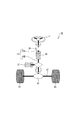
- the steering unit 35 has a known mechanical configuration such as a steering 41, a steering shaft 43, a rack and pinion 45, a tie rod 47, and the like.
- the steering 41 is rotatably held. Basically, when the steering 41 rotates, the steering shaft 43 also rotates in conjunction with it.
- the tie rod 47 connected to the steering shaft 43 by the rack and pinion 45 moves in the left-right direction in FIG. Thereby, the direction of the wheel 49 is changed, and steering is performed. Therefore, steering can be performed by the driver holding the steering wheel 41 and rotating it (that is, by performing steering steering).
- the amount of change in the direction of the wheel 49 at the time of steering (the magnitude of the turning angle) will be referred to as a steering amount.
- the steering unit 35 includes a motor 37 and a VGR (variable gear ratio) motor 39.
- the motor 37 applies rotational torque to the steering shaft 43.
- the direction of the rotational torque applied by the motor 37 is the direction that assists steering (that is, the rotational direction of the steering 41) when steering is performed due to the rotation of the steering 41 (that is, due to the steering of the driver). In the same direction).
- the direction of the rotational torque applied by the motor 37 is a direction in which the host vehicle steers in the direction in which the host vehicle should travel in order to avoid contact with an obstacle. Therefore, when performing steering avoidance, steering is automatically performed by the rotational torque applied by the motor 37 even if the driver does not rotate the steering 41.
- the VGR motor 39 is provided at a position where the steering shaft 43 is divided into two. Of the steering shaft 43, a portion above the VGR motor 39 is an upper shaft 43A, and a portion below the VGR motor 39 is a lower shaft 43B.
- the VGR motor 39 has a function of changing the rotation amount of the upper shaft 43A when the lower shaft 43B rotates by a unit amount.
- the rotation amount of the lower shaft 43B is proportional to the steering amount of the steering unit 35
- the rotation amount of the upper shaft 43A is proportional to the rotation amount of the steering 41. Therefore, the VGR motor 39 has a function of changing the rotation amount of the steering 41 per unit steering amount.
- the vehicle motion control unit 7 is an example of a steering control unit and a limiting unit.
- the avoidance travel control unit 5 is an example of a determination unit.
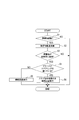
- step S1 the obstacle recognition unit 3 acquires the image data of the camera 9, the detection result of the millimeter wave radar 11, the detection result of the laser radar 13, and the detection result of the sonar 15. Then, the obstacle recognition unit 3 determines whether or not the obstacle has been recognized based on them. If the obstacle can be recognized, the process proceeds to step S2, and if the obstacle cannot be recognized, the process ends.
- step S2 the obstacle recognition unit 3 calculates the trajectory of the obstacle determined to have been recognized in step S1 (hereinafter referred to as an obstacle trajectory).
- the obstacle trajectory is a predicted trajectory of the obstacle in the future.
- the obstacle trajectory is calculated as follows. The data of the same obstacle as the obstacle recognized in the immediately preceding step S1 is retrieved retroactively, and the position is read out.
- the vehicle control device 1 stores obstacle data recognized in the past.
- the obstacle trajectory is calculated by arranging the positions of the obstacles in the order of time and connecting them. Then, assuming that the obstacle moves in the same direction at the same speed in the future, the obstacle trajectory is calculated by extrapolating to the past trajectory.
- step S3 the obstacle recognition unit 3 calculates a predicted trajectory of the host vehicle in the future (hereinafter referred to as the host vehicle track).
- the calculation method is the same as the calculation method of the obstacle trajectory.
- the vehicle trajectory calculated in this way and the obstacle trajectory calculated in step S2 are compared to determine whether or not the obstacle collides with the host vehicle.
- step S4 If it is determined that the obstacle does not collide, the process is terminated.
- step S4 the avoidance travel control unit 5 determines whether or not the driver is holding the steering wheel 41. Specifically, if the value of the torque detected by the torque sensor 29 is equal to or greater than the threshold value, it is determined that the driver is holding the steering 41, and otherwise, it is determined that the driver is not holding the steering 41. If it is determined that the driver is not gripping the steering wheel 41, the process proceeds to step S5. If the driver is determined to be gripping the steering wheel 41, the process proceeds to step S6.
- step S5 first, the avoidance travel control unit 5 determines the content of steering avoidance.
- Steering avoidance is a process of automatically steering and adjusting the vehicle speed to avoid collision with an obstacle.
- the contents of steering avoidance are the steering direction, the steering amount, and the target vehicle speed.
- the avoidance travel control unit 5 acquires signals from the locator 17, the four-wheel wheel speed sensor 19, the steering angle sensor 21, the front / rear G sensor 23, the left / right G sensor 25, and the yaw rate sensor 27. Recognize the situation of the vehicle (position, speed, acceleration, steering angle, yaw rate, etc.). Then, the avoidance travel control unit 5 determines the content of steering avoidance by combining the situation of the host vehicle and the obstacle track calculated in step S2.
- the vehicle motion control unit 7 executes the steering avoidance determined as described above. That is, steering is performed using the steering unit 35, and the vehicle speed is adjusted to the target vehicle speed using the driving force control unit 31 and the brake control unit 33.
- the steering here is automatic steering by the rotation of the motor 37.
- step S5 the rotation of the steering 41 is not limited when steering is avoided. That is, the relationship between the steering amount when steering is avoided and the rotation amount, rotation speed, etc. of the steering 41 is the relationship when the driver rotates the steering 41 (due to steering by the driver) and steers. It is the same.
- step S4 if a positive determination is made in step S4, the process proceeds to step 6.
- step S6 the avoidance travel control unit 5 and the vehicle motion control unit 7 perform steering avoidance basically in the same manner as in step S5.
- step S6 the vehicle motion control unit 7 limits the rotation of the steering 41 accompanying the steering when the steering avoidance is executed.
- the mode of restriction can be any of the following (i) to (iv).
- the limitation on the rotation of the steering 41 can be realized by changing the rotation amount of the upper shaft 43A when the lower shaft 43B rotates by a unit amount in the VGR motor 39.
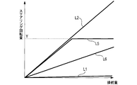
- FIG. 4 is a graph showing the relationship between the steering amount and the rotation amount of the steering 41.
- L2 is a curve representing the relationship between the steering amount and the rotation amount of the steering 41 when the driver performs steering by gripping the steering 41 and rotating it.
- FIG. 5 shows the relationship between the elapsed time and the rotation amount of the steering 41 when the steering amount is increased at a constant speed.
- the rotation amount of the steering 41 increases only at a slow speed equal to or lower than the upper limit X as shown by a curve L3 in FIG.
- the slope of the curve L3 in FIG. 5 (the amount of change in the steering rotation amount with respect to the unit amount of elapsed time) is X or less.
- the curve L4 is a curve when the driver holds the steering wheel 41 and performs steering by rotating the steering wheel 41.
- the upper limit is not provided for the rotational speed of the steering 41 (or an upper limit greater than the upper limit X is provided), the amount of rotation of the steering 41 can be rapidly increased compared to the curve L3. .
- the vehicle control device 1 uses any one of (i) to (iv) as a mode for restricting the rotation of the steering 41. As a result, driver discomfort can be reduced.
- the vehicle control device 1 determines whether or not the driver is grasping the steering 41, and restricts the rotation of the steering 41 on the condition that it is determined that the driver is grasping the steering 41. As a result, when the necessity is low, it is possible to prevent the process of limiting the rotation of the steering 41 from being executed.
- the vehicle control device 1 performs steering avoidance when an obstacle is recognized. Steering avoidance may be executed at an unexpected timing by the driver. Even in such a case, the vehicle control device 1 restricts the rotation of the steering 41 so that the driver's hand holding the steering 41 is intended. The driver's discomfort associated with being moved against the driver can be reduced.
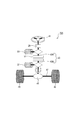
- the vehicle control device 1 includes a steering unit 135 shown in FIGS. 6 and 7.
- the steering unit 135 is of a type called a steer-by-wire system.
- the steering unit 135 has a known mechanical configuration such as a steering 41, a steering shaft 43, a rack and pinion 45, a tie rod 47, and the like.
- the steering 41 is rotatably held.
- the steering shaft 43 is divided into an upper shaft 43A and a lower shaft 43B, and a clutch 51 is provided between them.
- the clutch 51 normally separates the upper shaft 43A and the lower shaft 43B. When the upper shaft 43A and the lower shaft 43B are separated, even if one of the upper shaft 43A and the lower shaft 43B is rotationally driven, the driving force is not transmitted to the other.
- the clutch 51 connects the upper shaft 43A and the lower shaft 43B only in an emergency.
- the steering unit 135 includes a motor 37.
- the motor 37 is controlled by the vehicle motion control unit 7.
- the motor 37 applies rotational torque to the lower shaft 43B.
- the steering unit 135 is steered by the rotational torque applied by the motor 37.
- Steering by the driver rotating the steering wheel 41 is performed as follows.
- the torque sensor 29 detects the rotation direction and the rotation amount.
- the motor 37 applies steering torque to the lower shaft 43B according to the rotational direction and rotational amount detected by the torque sensor 29, and performs steering. Further, when performing steering avoidance, the motor 37 applies steering torque to the lower shaft 43B according to the content of steering avoidance determined by the avoidance travel control unit 5, and performs steering.
- the steering unit 135 includes a reaction force motor 53.
- the reaction force motor 53 is controlled by the vehicle motion control unit 7.
- the reaction force motor 53 applies a rotational torque in a direction opposite to the rotation to the upper shaft 43 ⁇ / b> A according to the rotational angle of the steering 41.
- the reaction force motor 53 has a function of generating an appropriate resistance when the driver rotates the steering wheel 41 and generating a steering feeling without a sense of incongruity.
- step S6 the vehicle control device 1 of the present embodiment limits the rotation of the steering 41 in any one of the above-described (i) to (iv) as in the first embodiment.
- the rotation of the steering motor 41 is limited by controlling the rotation of the reaction force motor 53.
- the steering motor 41 is prevented from rotating by not rotating the reaction force motor 53.
- an upper limit is provided for the rotational speed of the steering 41 by providing an upper limit for the rotational speed of the reaction force motor 53.
- an upper limit is provided for the rotation amount of the steering 41 by providing an upper limit for the rotation amount of the reaction force motor 53.
- the rotation amount of the steering 41 per unit steering amount is reduced by reducing the rotation amount of the reaction force motor 53 per unit steering amount.
- the vehicle control device 1 When executing steering avoidance, the vehicle control device 1 performs steering by the motor 37 and rotates the steering 41 by the reaction force motor 53. Therefore, the degree of freedom when restricting the rotation of the steering 41 is further increased.
- the mode of limiting the rotation of the steering 41 may be other than the above (i) to (iv).
- an upper limit may be provided for the rotational speed of the steering 41, and an upper limit may be provided for the amount of rotation of the steering 41 as described in (iii).
- an upper limit may be provided for the rotational speed of the steering 41, and the rotational amount of the steering 41 per unit steering amount may be reduced as in (iv).
- an upper limit may be provided for the rotation amount of the steering 41, and as in (iv), the rotation amount of the steering 41 per unit steering amount may be reduced.
- the vehicle control device 1 may have an automatic travel function for traveling the host vehicle along a preset route. During automatic traveling, steering is appropriately performed so that the host vehicle does not deviate from the route.
- the steering can be performed by controlling the steering units 35 and 135 by the vehicle motion control unit 7 as in the case of performing steering avoidance. Then, when steering is performed during automatic traveling, the rotation of the steering 41 may be restricted as in the first and second embodiments.
- step S4 it may be determined whether the driver is holding the steering wheel 41 by means other than the torque sensor 29.
- a contact sensor provided on the steering 41 may determine whether the driver is holding the steering 41.
- the vehicle control device 1 may limit the rotation of the steering 41 regardless of whether or not the driver holds the steering 41.
- the functions of one constituent element in the above embodiment may be distributed as a plurality of constituent elements, or the functions of a plurality of constituent elements may be integrated into one constituent element. Further, at least a part of the configuration of the above embodiment may be replaced with a known configuration having the same function. Moreover, you may abbreviate
- a system including the vehicle control device as a constituent element, a program for causing a computer to function as the vehicle control device, a medium recording the program, a vehicle control method, and a rotation limit of a handle
- the present disclosure can also be realized in various forms such as a method.
Landscapes
- Engineering & Computer Science (AREA)
- Chemical & Material Sciences (AREA)
- Combustion & Propulsion (AREA)
- Transportation (AREA)
- Mechanical Engineering (AREA)
- Steering Control In Accordance With Driving Conditions (AREA)
Abstract
車両制御装置(1)は、車両の操舵を行う操舵ユニット(35、135)と、車両の操舵と連動して回転するステアリング(41)とを備える車両に用いられる。車両制御装置(1)は、操舵制御ユニット(7)及び制限ユニット(7)を備える。操舵制御ユニットは、操舵ユニットを用いて車両の操舵を行う。制限ユニットは、操舵制御ユニットが車両の操舵を行う第1の場合、車両のドライバによるステアリング操舵に起因して車両の操舵を行う第2の場合と比べて、車両の操舵に伴うステアリングの回転を制限する。
Description
本出願は、2015年6月4日に出願された日本出願番号2015-114164号に基づくものであって、その優先権の利益を主張するものであり、その特許出願のすべての内容が、参照により本明細書に組み入れられる。
本開示は、車両制御装置及び車両制御方法に関する。
最近の車両では、ドライバのステアリング操舵を検出し、操舵トルクに応じてモータで操舵力をアシストする電動パワーステアリングシステムが一般的である。さらに近年では、ドライバの意思によらず自動で操舵する機能を搭載する車両も量産され、この機能は電動パワーステアリングによって実現される場合が多い。
また、自車両の前方に障害物を検出したとき、通常より回頭性が向上した回避走行モードに移行する技術が提案されている(特許文献1参照)。
自車両の前方に障害物を検出したとき等に、自動的に操舵を行う車両制御装置が考えられる。車両制御装置が自動的に操舵を行ったとき、操舵シャフトはステアリングシャフトと連結しているため、ステアリングは連動して回転する。この場合、ステアリングを握っていたドライバの手は、意思に反して動かされるため、ドライバに不快感を与えるおそれがある。
本開示は、ドライバに不快感を与えにくい車両制御装置及び車両制御方法を提供することを目的とする。
本開示の第1の態様によれば、車両の操舵を行う操舵ユニットと、車両の操舵と連動して回転するステアリングとを備える車両に用いられる車両制御装置であって、操舵ユニットを用いて車両の操舵を行う操舵制御ユニットと、操舵制御ユニットが車両の操舵を行う第1の場合、車両のドライバによるステアリング操舵に起因して車両の操舵を行う第2の場合に比べて、車両の操舵に伴うステアリングの回転を制限する制限ユニットと、を備える車両制御装置が提供される。
本開示の第2の態様によれば、車両の操舵を行う操舵ユニットと、車両の操舵と連動して回転するステアリングとを備える車両に搭載される操舵制御ユニットにより、操舵ユニットを用いて車両の操舵を行い、車両に搭載される制限ユニットにより、操舵制御ユニットが車両の操舵を行う第1の場合、車両のドライバによるステアリング操舵に起因して車両の操舵を行う第2の場合と比べて、車両の操舵に伴うステアリングの回転を制限する車両制御方法が提供される。
これによれば、操舵制御ユニットが車両の操舵を行う第1の場合は、車両のドライバによるステアリング操舵に起因して車両の操舵を行う第2の場合に比べて、車両の操舵に伴うステアリングの回転を制限することができる。これにより、ステアリングを握っていたドライバの手が意思に反して動かされることに伴うドライバの不快感を低減することができる。
本開示についての上記の目的、その他の目的、特徴、及び利点は、添付の図面を参照しながら下記の詳細な記述により、より明確になる。その図面は、
第1の実施形態に係る車両制御装置の構成を表すブロック図であり、
第1の実施形態に係る車両制御装置が搭載される車両の操舵ユニットの構成を表す説明図であり、
第1の実施形態に係る車両制御装置が実行する処理を表すフローチャートであり、
第1の実施形態において、操舵量とステアリングの回転量との関係を表すグラフであり、
第1の実施形態において、一定の速度で操舵量を増していくときの、経過時間と、ステアリングの回転量との関係を表すグラフであり、
第2の実施形態に係る車両制御装置が搭載される車両の操舵ユニットの構成を表す説明図であり、
第2の実施形態に係る車両制御装置の構成を表すブロック図である。
以下、本開示の実施形態を図面に基づき説明する。
<第1の実施形態>
最初に、第1の実施形態について説明する。
最初に、第1の実施形態について説明する。
1.車両制御装置1の構成
車両制御装置1の構成を図1、図2に基づき説明する。車両制御装置1は車両に搭載される車載装置である。以下では、車両制御装置1を搭載する車両を自車両とする。車両制御装置1は、CPU(central processing unit)、RAM(random access memory)、ROM(read only memory)等を備える公知のコンピュータである。車両制御装置1は、ROMに記憶されたプログラムにより後述する処理を実行する。
車両制御装置1の構成を図1、図2に基づき説明する。車両制御装置1は車両に搭載される車載装置である。以下では、車両制御装置1を搭載する車両を自車両とする。車両制御装置1は、CPU(central processing unit)、RAM(random access memory)、ROM(read only memory)等を備える公知のコンピュータである。車両制御装置1は、ROMに記憶されたプログラムにより後述する処理を実行する。
図1に示すように、車両制御装置1は、機能的に、障害物認識ユニット3、回避走行制御ユニット5、及び車両運動制御ユニット7を備える。各ユニット3、5、7の機能は後述する。
自車両は、車両制御装置1に加えて、カメラ9、ミリ波レーダー11、レーザーレーダー13、ソナー15、ロケーター17、四輪車輪速センサ19、ステアリング角センサ21、前後Gセンサ23、左右Gセンサ25、ヨーレートセンサ27、トルクセンサ29、駆動力制御ユニット31、ブレーキ制御ユニット33、及び操舵ユニット35を備える。
カメラ9は、自車両の周囲を撮影し、画像データを作成する。ミリ波レーダー11、レーザーレーダー13、及びソナー15は、いずれも、自車両の周囲に存在する障害物(例えば、他の車両、歩行者、固定物等)を検出する。ロケーター17はGPS(global positioning system)を備えており、自車両の位置データを取得する。四輪車輪速センサ19は、自車両の車輪速を検出する。ステアリング角センサ21は、自車両のステアリングにおける角度(基準となる位置からの回転量)を検出する。
前後Gセンサ23は、自車両の前後方向での加速度を検出する。左右Gセンサ25は、自車両の左右方向(車幅方向)での加速度を検出する。ヨーレートセンサ27は、自車両のヨーレートを検出する。トルクセンサ29は、ステアリングの回転トルクを検出する。なお、トルクセンサ29により検出される回転トルクは、自車両のドライバが通常のステアリング操舵を行い、ステアリングを回転させるときに発生するものである。駆動力制御ユニット31は、自車両の駆動力を制御する。ブレーキ制御ユニット33は、自車両のブレーキ動作を制御する。操舵ユニット35は自車両の操舵を行う。
次に、図1、図2を用いて操舵ユニット35をさらに説明する。
操舵ユニット35は、ステアリング41、ステアリングシャフト43、ラックアンドピニオン45、タイロッド47等、周知の機械的な構成を備える。ステアリング41は、回転可能に保持されている。基本的には、ステアリング41が回転すると、ステアリングシャフト43も連動して回転する。ステアリングシャフト43が回転すると、ラックアンドピニオン45によってステアリングシャフト43と連結されているタイロッド47が図2における左右方向に移動する。これにより、車輪49の向きが変わり、操舵が行われる。よって、ドライバがステアリング41を握り、それを回転させることにより(すなわち、ステアリング操舵を行うことにより)、操舵を行うことができる。以下では、操舵を行ったときの車輪49における向きの変化量(切れ角の大きさ)を操舵量とする。
さらに、操舵ユニット35は、モータ37、及びVGR(variable gear ratio)モータ39を備える。モータ37は、ステアリングシャフト43に対し回転トルクを付与する。モータ37が付与する回転トルクの方向は、ステアリング41の回転に起因して(すなわち、ドライバのステアリング操舵に起因して)操舵を行う場合は、操舵を補助する方向(すなわち、ステアリング41の回転方向と同じ方向)である。
また、後述する操舵回避を行う場合、モータ37が付与する回転トルクの方向は、障害物との接触を避けるために自車両が進むべき方向に操舵する方向である。よって、操舵回避を行う場合、ドライバがステアリング41を回転させなくても、モータ37が付与する回転トルクにより自動的に操舵が行われる。
VGRモータ39は、ステアリングシャフト43を2分割する位置に設けられている。ステアリングシャフト43のうち、VGRモータ39よりも上の部分を上部シャフト43Aとし、VGRモータ39よりも下の部分を下部シャフト43Bとする。VGRモータ39は、下部シャフト43Bが単位量回転したときの上部シャフト43Aの回転量を変化させる機能を有する。
ここで、下部シャフト43Bの回転量は操舵ユニット35の操舵量に比例し、上部シャフト43Aの回転量はステアリング41の回転量に比例する。よって、VGRモータ39は、単位操舵量当りのステアリング41の回転量を変化させる機能を有する。
なお、車両運動制御ユニット7は、操舵制御ユニット及び制限ユニットの一例である。回避走行制御ユニット5は、判断ユニットの一例である。
2.車両制御装置1が実行する処理
次に、車両制御装置1が所定時間ごとに繰り返し実行する処理について、図3~図5に基づき説明する。
次に、車両制御装置1が所定時間ごとに繰り返し実行する処理について、図3~図5に基づき説明する。
図3において、ステップS1では、障害物認識ユニット3が、カメラ9の画像データ、ミリ波レーダー11の検出結果、レーザーレーダー13の検出結果、及びソナー15の検出結果を取得する。そして、障害物認識ユニット3は、それらに基づき障害物を認識できたか否かを判断する。障害物を認識できた場合はステップS2に進み、障害物を認識できなかった場合は本処理を終了する。
ステップS2では、障害物認識ユニット3が、ステップS1で認識したと判断した障害物の軌道(以下、障害物軌道とする)を演算する。障害物軌道とは、障害物の将来における予測軌道である。障害物軌道は以下のように演算する。直前のステップS1で認識した障害物と同じ障害物のデータを過去に遡って検索し、その位置を読み出す。なお、車両制御装置1は、過去に認識した障害物のデータを記憶している。
次に、障害物の位置を時間の経過順に沿って並べ、それらを結ぶことで、障害物の過去の軌道を演算する。そして、障害物が、将来においても同じ方向に同じ速度で移動すると仮定し、過去の軌道に外挿して、障害物軌道を演算する。
ステップS3では、障害物認識ユニット3が、自車両の将来における予測軌道(以下、自車両軌道とする)を演算する。その演算方法は、障害物軌道の演算方法と同様である。次に、このように演算した自車両軌道と、ステップS2で演算した障害物軌道とを対比し、障害物が自車両に衝突するか否かを判断する。
すなわち、自車両軌道と障害物軌道とが交差しており、その交差している位置に自車両が到達するタイミングと障害物が到達するタイミングとが同じであれば、障害物が自車両に衝突すると判断し、それ以外であれば両者は衝突しないと判断する。障害物が自車両に衝突すると判断した場合はステップS4に進み、衝突しないと判断した場合は本処理を終了する。
ステップS4では、ドライバがステアリング41を握っているか否かを回避走行制御ユニット5が判断する。具体的には、トルクセンサ29により検出したトルクの値が閾値以上であればドライバがステアリング41を握っていると判断し、それ以外の場合はドライバがステアリング41を握っていないと判断する。ドライバがステアリング41を握っていないと判断した場合はステップS5に進み、ドライバがステアリング41を握っていると判断した場合はステップS6に進む。
ステップS5では、まず、回避走行制御ユニット5が、操舵回避の内容を決める。操舵回避とは、障害物との衝突を避けるために自動的に操舵を行い、車速を調整する処理である。操舵回避の内容とは、操舵する方向と、操舵量と、目標車速とである。
操舵回避の内容を決めるために、回避走行制御ユニット5は、ロケーター17、四輪車輪速センサ19、ステアリング角センサ21、前後Gセンサ23、左右Gセンサ25、及びヨーレートセンサ27から信号を取得し、自車両の状況(位置、速度、加速度、ステアリング角、ヨーレート等)を認識する。そして、回避走行制御ユニット5は、自車両の状況と、ステップS2で演算した障害物軌道とを総合して、操舵回避の内容を決める。
次に、車両運動制御ユニット7は、上記のように内容を決めた操舵回避を実行する。すなわち、操舵ユニット35を用いて、操舵を行い、駆動力制御ユニット31及びブレーキ制御ユニット33を用いて車速を目標車速に調整する。ここでの操舵は、モータ37の回転による自動操舵である。
なお、ステップS5では、操舵回避を行うとき、ステアリング41の回転は制限されない。すなわち、操舵回避を行うときの操舵量とステアリング41の回転量、回転速度等との関係は、ドライバがステアリング41を回転させて(ドライバのステアリング操舵に起因して)操舵を行う場合の関係と同様である。
一方、ステップS4で肯定判断された場合は、ステップ6に進む。ステップS6では、回避走行制御ユニット5及び車両運動制御ユニット7が、基本的にはステップS5と同様に操舵回避を実行する。
ただし、ステップS6では、車両運動制御ユニット7が、操舵回避を実行するときの操舵に伴うステアリング41の回転を制限する。制限の態様は、以下の(i)~(iv)のいずれかとすることができる。ステアリング41の回転に対する制限は、VGRモータ39における、下部シャフト43Bが単位量回転したときの上部シャフト43Aの回転量を変化させることで実現できる。
(i)操舵を行っても、ステアリング41を回転させない。この場合の操舵量とステアリング41の回転量との関係を、図4におけるL1の曲線により示す。L1の曲線において、操舵量が増加しても、ステアリング41の回転量は0のままである。
なお、図4は、操舵量とステアリング41の回転量との関係を表すグラフである。L2は、ドライバがステアリング41を握り、それを回転させることにより操舵を行うときの、操舵量とステアリング41の回転量との関係を表す曲線である。
(ii)ステアリング41の回転速度に上限を設ける。この場合のステアリング41の挙動を図5に表す。図5は、一定の速度で操舵量を増していくときの、経過時間と、ステアリング41の回転量との関係を表す。ステアリング41の回転速度に上限Xを設けた場合、図5の曲線L3のように、ステアリング41の回転量は、上限X以下のゆっくりとした速度でしか上昇しない。図5における曲線L3の傾き(経過時間の単位量に対するステアリング回転量の変化量)はX以下である。
なお、曲線L4は、ドライバがステアリング41を握り、それを回転させることにより操舵を行う場合の曲線である。この場合、ステアリング41の回転速度に上限は設けられていない(あるいは上限Xよりも大きい上限が設けられている)ので、曲線L3に比べて、ステアリング41の回転量が急速に上昇することができる。
(iii)ステアリング41の回転量に上限を設ける。この場合のステアリング41の挙動を図4における曲線L5により示す。L5の曲線において、操舵量が小さいうちは、操舵量の増加に応じてステアリング41の回転量が増加するが、ステアリング41の回転量が上限Yに達すると、さらに操舵量が増加したとしても、ステアリング41はそれ以上回転しない。
(iv)単位操舵量当りのステアリング41の回転量を少なくする。この場合のステアリング41の挙動を図4における曲線L6により示す。L6の曲線は、L2の曲線に比べて、単位操舵量当りのステアリング41の回転量が少ない。
3.車両制御装置1が奏する効果
(1A)車両制御装置1は、車両運動制御ユニット7が操舵回避の一環として操舵を行う場合(第1の場合)は、ドライバのステアリング操舵に起因して操舵を行う場合(第2の場合)に比べて、操舵に伴うステアリング41の回転を制限する。そのことにより、ステアリング41を握っているドライバの手が意に反して動かされることに伴うドライバの不快感を低減できる。
(1A)車両制御装置1は、車両運動制御ユニット7が操舵回避の一環として操舵を行う場合(第1の場合)は、ドライバのステアリング操舵に起因して操舵を行う場合(第2の場合)に比べて、操舵に伴うステアリング41の回転を制限する。そのことにより、ステアリング41を握っているドライバの手が意に反して動かされることに伴うドライバの不快感を低減できる。
(1B)車両制御装置1は、ステアリング41の回転を制限する態様として、前記(i)~(iv)のいずれかを用いる。そのことにより、ドライバの不快感を低減できる。
(1C)車両制御装置1は、ドライバがステアリング41を握っているか否かを判断し、ドライバがステアリング41を握っていると判断したことを条件として、ステアリング41の回転を制限する。そのことにより、必要性が低い場合は、ステアリング41の回転を制限する処理を実行しないようにすることができる。
(1D)車両制御装置1は、障害物を認識したときに操舵回避を行う。操舵回避は、ドライバが予期せぬタイミングで実行されることがあるが、その場合でも、車両制御装置1は、ステアリング41の回転を制限することにより、ステアリング41を握っているドライバの手が意に反して動かされることに伴うドライバの不快感を低減できる。
<第2の実施形態>
第2の実施形態は、基本的な構成は第1の実施形態と同様であるため、共通する構成については説明を省略し、相違点を中心に説明する。
第2の実施形態は、基本的な構成は第1の実施形態と同様であるため、共通する構成については説明を省略し、相違点を中心に説明する。
1.第1の実施形態との相違点
車両制御装置1は、図6、図7に示す操舵ユニット135を備える。操舵ユニット135は、ステアバイワイヤシステムと呼ばれる形式のものである。操舵ユニット135は、ステアリング41、ステアリングシャフト43、ラックアンドピニオン45、タイロッド47等、周知の機械的な構成を備える。ステアリング41は回転可能に保持されている。
車両制御装置1は、図6、図7に示す操舵ユニット135を備える。操舵ユニット135は、ステアバイワイヤシステムと呼ばれる形式のものである。操舵ユニット135は、ステアリング41、ステアリングシャフト43、ラックアンドピニオン45、タイロッド47等、周知の機械的な構成を備える。ステアリング41は回転可能に保持されている。
ステアリングシャフト43は、上部シャフト43Aと下部シャフト43Bとに分けられており、それらの間にクラッチ51が設けられている。クラッチ51は、通常、上部シャフト43Aと下部シャフト43Bとを分離している。上部シャフト43Aと下部シャフト43Bとが分離しているとき、上部シャフト43A及び下部シャフト43Bの一方を回転駆動しても、その駆動力は他方に伝達されない。クラッチ51は、非常時のみ、上部シャフト43Aと下部シャフト43Bとを接続する。
さらに、操舵ユニット135は、モータ37を備える。モータ37は、車両運動制御ユニット7により制御される。モータ37は、下部シャフト43Bに対し回転トルクを付与する。操舵ユニット135の操舵は、モータ37が付与する回転トルクにより行われる。
ドライバがステアリング41を回転させることによる操舵は、以下のように行われる。ドライバがステアリング41を回転させると、トルクセンサ29が、その回転方向、及び回転量を検出する。モータ37は、トルクセンサ29で検出した回転方向及び回転量に応じた回転トルクを下部シャフト43Bに付与し、操舵を行う。また、操舵回避を行う場合は、回避走行制御ユニット5が決めた操舵回避の内容に応じた回転トルクを、モータ37が下部シャフト43Bに付与し、操舵を行う。
さらに、操舵ユニット135は、反力モータ53を備える。反力モータ53は、車両運動制御ユニット7により制御される。反力モータ53は、ドライバがステアリング41を回転させたとき、その回転とは反対方向の回転トルクをステアリング41の回転角度に応じて上部シャフト43Aに付与する。反力モータ53は、ドライバがステアリング41を回転させるとき、適度な抵抗を生じさせ、違和感のない操舵フィーリングを生じさせる機能を有する。
本実施形態の車両制御装置1は、ステップS6において、第1の実施形態と同様に、前記(i)~(iv)のいずれかの態様でステアリング41の回転を制限する。ただし、本実施形態では、反力モータ53の回転を制御することで、ステアリング41の回転を制限する。
すなわち、前記(i)の態様の場合、反力モータ53を回転させないことにより、ステアリング41を回転させないようにする。また、前記(ii)の態様の場合、反力モータ53の回転速度に上限を設けることで、ステアリング41の回転速度に上限を設ける。また、前記(iii)の態様の場合、反力モータ53の回転量に上限を設けることで、ステアリング41の回転量に上限を設ける。また、前記(iV)の態様の場合、単位操舵量当りの反力モータ53の回転量を少なくすることで、単位操舵量当りのステアリング41の回転量を少なくする。
2.車両制御装置1が奏する効果
以上詳述した第2の実施形態によれば、前述した第1の実施形態の効果(1A)~(1D)に加え、以下の効果が得られる。
以上詳述した第2の実施形態によれば、前述した第1の実施形態の効果(1A)~(1D)に加え、以下の効果が得られる。
(2A)車両制御装置1は、操舵回避を実行するとき、操舵をモータ37により行い、ステアリング41の回転を反力モータ53により行う。そのため、ステアリング41の回転を制限するときの自由度が一層大きい。
<その他の実施形態>
以上、本開示の実施形態について説明したが、本開示は上記の実施形態に限定されることなく、種々の形態を採り得る。
以上、本開示の実施形態について説明したが、本開示は上記の実施形態に限定されることなく、種々の形態を採り得る。
(1)第1、第2の実施形態において、ステアリング41の回転を制限する態様は、前記(i)~(iv)以外のものであってもよい。例えば、前記(ii)のように、ステアリング41の回転速度に上限を設けるとともに、前記(iii)のように、ステアリング41の回転量に上限を設けてもよい。また、前記(ii)のように、ステアリング41の回転速度に上限を設けるとともに、前記(iv)のように、単位操舵量当りのステアリング41の回転量を少なくしてもよい。また、前記(iii)のように、ステアリング41の回転量に上限を設けるとともに、前記(iv)のように、単位操舵量当りのステアリング41の回転量を少なくしてもよい。
(2)車両制御装置1は、予め設定された経路に沿って自車両を走行させる自動走行機能を備えていてもよい。自動走行中は、自車両が経路から逸脱しないように、適宜操舵を行う。その操舵は、操舵回避を実行する場合と同様に、車両運動制御ユニット7が操舵ユニット35、135を制御して行うことができる。そして、自動走行中に操舵を行うとき、第1、第2の実施形態のように、ステアリング41の回転を制限してもよい。
(3)ステップS4において、トルクセンサ29以外の手段により、ドライバがステアリング41を握っているか否かを判断してもよい。例えば、ステアリング41に設けた接触センサにより、ドライバがステアリング41を握っているか否かを判断してもよい。
(4)車両制御装置1は、ドライバがステアリング41を握っているか否かによらず、ステアリング41の回転を制限してもよい。
(5)上記実施形態における1つの構成要素が有する機能を複数の構成要素として分散させたり、複数の構成要素が有する機能を1つの構成要素に統合させたりしてもよい。また、上記実施形態の構成の少なくとも一部を、同様の機能を有する公知の構成に置き換えてもよい。また、上記実施形態の構成の一部を省略してもよい。また、上記実施形態の構成の少なくとも一部を、他の上記実施形態の構成に対して付加又は置換してもよい。なお、特許請求の範囲に記載した文言のみによって特定される技術思想に含まれるあらゆる態様が本開示の実施形態である。
(6)上述した車両制御装置の他、当該車両制御装置を構成要素とするシステム、当該車両制御装置としてコンピュータを機能させるためのプログラム、このプログラムを記録した媒体、車両制御方法、ハンドルの回転制限方法等、種々の形態で本開示を実現することもできる。
Claims (7)
- 車両の操舵を行う操舵ユニット(35、135)と、前記車両の操舵と連動して回転するステアリング(41)とを備える車両に用いられる車両制御装置(1)であって、
前記操舵ユニットを用いて前記車両の操舵を行う操舵制御ユニット(7)と、
前記操舵制御ユニットが前記車両の操舵を行う第1の場合、前記車両のドライバによるステアリング操舵に起因して前記車両の操舵を行う第2の場合と比べて、前記車両の操舵に伴う前記ステアリングの回転を制限する制限ユニット(7)と、
を備えることを特徴とする車両制御装置。 - 請求項1に記載の車両制御装置であって、
前記制限ユニットは、前記第1の場合、前記車両の操舵を行っても、前記ステアリングを回転させないことを特徴とする車両制御装置。 - 請求項1に記載の車両制御装置であって、
前記制限ユニットは、前記第1の場合、前記第2の場合と比べて、前記ステアリングの回転速度、及び/又は、前記ステアリングの回転量について、上限を低くすることを特徴とする車両制御装置。 - 請求項1に記載の車両制御装置であって、
前記制限ユニットは、前記第1の場合、前記第2の場合と比べて、単位操舵量当りの前記ステアリングの回転量を少なくすることを特徴とする車両制御装置。 - 請求項1~4のいずれか1項に記載の車両制御装置であって、
前記ドライバが前記ステアリングを握っているか否かを判断する判断ユニット(5)をさらに備え、
前記制限ユニットは、前記ドライバが前記ステアリングを握っていると前記判断ユニットが判断したことを条件として、前記第1の場合、前記第2の場合と比べて、前記車両の操舵に伴う前記ステアリングの回転を制限することを特徴とする車両制御装置。 - 請求項1~5のいずれか1項に記載の車両制御装置であって、
障害物を認識する障害物認識ユニット(3)をさらに備え、
前記操舵制御ユニットは、前記障害物認識ユニットが障害物を認識したときに前記車両の操舵を行うことを特徴とする車両制御装置。 - 車両の操舵を行う操舵ユニット(35、135)と、前記車両の操舵と連動して回転するステアリング(41)とを備える車両に搭載される操舵制御ユニット(7)により、前記操舵ユニットを用いて前記車両の操舵を行い、
前記車両に搭載される制限ユニット(7)により、前記操舵制御ユニットが前記車両の操舵を行う第1の場合、前記車両のドライバによるステアリング操舵に起因して前記車両の操舵を行う第2の場合と比べて、前記車両の操舵に伴う前記ステアリングの回転を制限する、
ことを特徴とする車両制御方法。
Applications Claiming Priority (2)
| Application Number | Priority Date | Filing Date | Title |
|---|---|---|---|
| JP2015114164A JP2017001415A (ja) | 2015-06-04 | 2015-06-04 | 車両制御装置 |
| JP2015-114164 | 2015-06-04 |
Publications (1)
| Publication Number | Publication Date |
|---|---|
| WO2016194862A1 true WO2016194862A1 (ja) | 2016-12-08 |
Family
ID=57440249
Family Applications (1)
| Application Number | Title | Priority Date | Filing Date |
|---|---|---|---|
| PCT/JP2016/065859 Ceased WO2016194862A1 (ja) | 2015-06-04 | 2016-05-30 | 車両制御装置及び車両制御方法 |
Country Status (2)
| Country | Link |
|---|---|
| JP (1) | JP2017001415A (ja) |
| WO (1) | WO2016194862A1 (ja) |
Cited By (1)
| Publication number | Priority date | Publication date | Assignee | Title |
|---|---|---|---|---|
| WO2018131695A1 (ja) * | 2017-01-12 | 2018-07-19 | 望月玲於奈 | 操作装置 |
Families Citing this family (1)
| Publication number | Priority date | Publication date | Assignee | Title |
|---|---|---|---|---|
| JP6577081B1 (ja) * | 2018-03-30 | 2019-09-18 | 株式会社フジクラ | 照射装置、金属造形装置、金属造形システム、照射方法、及び金属造形物の製造方法 |
Citations (4)
| Publication number | Priority date | Publication date | Assignee | Title |
|---|---|---|---|---|
| JP2002012159A (ja) * | 2000-06-29 | 2002-01-15 | Toyota Motor Corp | 車輌用自動操舵装置 |
| JP2002264826A (ja) * | 2001-03-09 | 2002-09-18 | Toyota Motor Corp | 移動体の自動運転装置 |
| JP2003170851A (ja) * | 2001-12-06 | 2003-06-17 | Toyota Motor Corp | 車輌用自動操舵装置 |
| JP2004224238A (ja) * | 2003-01-24 | 2004-08-12 | Honda Motor Co Ltd | 操舵装置 |
-
2015
- 2015-06-04 JP JP2015114164A patent/JP2017001415A/ja active Pending
-
2016
- 2016-05-30 WO PCT/JP2016/065859 patent/WO2016194862A1/ja not_active Ceased
Patent Citations (4)
| Publication number | Priority date | Publication date | Assignee | Title |
|---|---|---|---|---|
| JP2002012159A (ja) * | 2000-06-29 | 2002-01-15 | Toyota Motor Corp | 車輌用自動操舵装置 |
| JP2002264826A (ja) * | 2001-03-09 | 2002-09-18 | Toyota Motor Corp | 移動体の自動運転装置 |
| JP2003170851A (ja) * | 2001-12-06 | 2003-06-17 | Toyota Motor Corp | 車輌用自動操舵装置 |
| JP2004224238A (ja) * | 2003-01-24 | 2004-08-12 | Honda Motor Co Ltd | 操舵装置 |
Cited By (5)
| Publication number | Priority date | Publication date | Assignee | Title |
|---|---|---|---|---|
| WO2018131695A1 (ja) * | 2017-01-12 | 2018-07-19 | 望月玲於奈 | 操作装置 |
| JPWO2018131695A1 (ja) * | 2017-01-12 | 2019-11-07 | 玲於奈 望月 | 操作装置 |
| US11198470B2 (en) | 2017-01-12 | 2021-12-14 | Leona MOCHIZUKI | Operation device |
| JP2022000374A (ja) * | 2017-01-12 | 2022-01-04 | 望月 貴里子 | 操作装置 |
| JP7322112B2 (ja) | 2017-01-12 | 2023-08-07 | 望月 貴里子 | 操作装置 |
Also Published As
| Publication number | Publication date |
|---|---|
| JP2017001415A (ja) | 2017-01-05 |
Similar Documents
| Publication | Publication Date | Title |
|---|---|---|
| US8489281B2 (en) | Method for operating an automobile and an automobile with an environmental detection device | |
| JP3905727B2 (ja) | 車両の車線追従制御装置 | |
| US9937954B2 (en) | Steering reaction force control apparatus for vehicle | |
| JP6763327B2 (ja) | 衝突回避装置 | |
| EP1864881A1 (en) | Vehicle steering system | |
| US11214300B2 (en) | System and method for operating a motor vehicle | |
| JP6790807B2 (ja) | 車両走行制御装置及び自動運転制御方法 | |
| JP7243828B2 (ja) | 操舵制御方法及び操舵制御装置 | |
| CN105050884B (zh) | 碰撞避免辅助装置和碰撞避免辅助方法 | |
| JP2012516806A (ja) | 回避運転を実行するための方法および装置 | |
| JP2019089521A (ja) | 車両の車線逸脱防止制御装置 | |
| CN108238100A (zh) | 车辆行驶控制装置和自动驾驶控制方法 | |
| JP2020032949A (ja) | 自動運転システム | |
| JP7548877B2 (ja) | 車両制御システム及び車両制御方法 | |
| JP4811188B2 (ja) | 車両の操舵制御装置 | |
| JP2010158987A (ja) | 車両用転舵制御装置 | |
| JP2019014433A (ja) | 車両の操舵制御装置 | |
| WO2016194862A1 (ja) | 車両制御装置及び車両制御方法 | |
| US12466473B2 (en) | Steering device | |
| JP2019014432A (ja) | 車両の操舵制御装置 | |
| JP2008189053A (ja) | 操舵支援装置 | |
| JP2007168641A (ja) | 可変舵角操舵装置及びその方法、並びにその可変舵角操舵装置を搭載した自動車 | |
| JP2018047885A (ja) | 車両の操舵装置 | |
| JP2017154512A (ja) | 車両制御装置 | |
| US20250333100A1 (en) | Vehicel control method and device |
Legal Events
| Date | Code | Title | Description |
|---|---|---|---|
| 121 | Ep: the epo has been informed by wipo that ep was designated in this application |
Ref document number: 16803297 Country of ref document: EP Kind code of ref document: A1 |
|
| NENP | Non-entry into the national phase |
Ref country code: DE |
|
| 122 | Ep: pct application non-entry in european phase |
Ref document number: 16803297 Country of ref document: EP Kind code of ref document: A1 |