WO2016194491A1 - 車両制御装置、及び車両制御方法 - Google Patents
車両制御装置、及び車両制御方法 Download PDFInfo
- Publication number
- WO2016194491A1 WO2016194491A1 PCT/JP2016/062096 JP2016062096W WO2016194491A1 WO 2016194491 A1 WO2016194491 A1 WO 2016194491A1 JP 2016062096 W JP2016062096 W JP 2016062096W WO 2016194491 A1 WO2016194491 A1 WO 2016194491A1
- Authority
- WO
- WIPO (PCT)
- Prior art keywords
- unit
- target
- determination result
- determination
- vehicle
- Prior art date
- Legal status (The legal status is an assumption and is not a legal conclusion. Google has not performed a legal analysis and makes no representation as to the accuracy of the status listed.)
- Ceased
Links
Images


Classifications
-
- B—PERFORMING OPERATIONS; TRANSPORTING
- B60—VEHICLES IN GENERAL
- B60T—VEHICLE BRAKE CONTROL SYSTEMS OR PARTS THEREOF; BRAKE CONTROL SYSTEMS OR PARTS THEREOF, IN GENERAL; ARRANGEMENT OF BRAKING ELEMENTS ON VEHICLES IN GENERAL; PORTABLE DEVICES FOR PREVENTING UNWANTED MOVEMENT OF VEHICLES; VEHICLE MODIFICATIONS TO FACILITATE COOLING OF BRAKES
- B60T7/00—Brake-action initiating means
- B60T7/12—Brake-action initiating means for automatic initiation; for initiation not subject to will of driver or passenger
- B60T7/22—Brake-action initiating means for automatic initiation; for initiation not subject to will of driver or passenger initiated by contact of vehicle, e.g. bumper, with an external object, e.g. another vehicle, or by means of contactless obstacle detectors mounted on the vehicle
-
- B—PERFORMING OPERATIONS; TRANSPORTING
- B60—VEHICLES IN GENERAL
- B60T—VEHICLE BRAKE CONTROL SYSTEMS OR PARTS THEREOF; BRAKE CONTROL SYSTEMS OR PARTS THEREOF, IN GENERAL; ARRANGEMENT OF BRAKING ELEMENTS ON VEHICLES IN GENERAL; PORTABLE DEVICES FOR PREVENTING UNWANTED MOVEMENT OF VEHICLES; VEHICLE MODIFICATIONS TO FACILITATE COOLING OF BRAKES
- B60T8/00—Arrangements for adjusting wheel-braking force to meet varying vehicular or ground-surface conditions, e.g. limiting or varying distribution of braking force
- B60T8/17—Using electrical or electronic regulation means to control braking
-
- B—PERFORMING OPERATIONS; TRANSPORTING
- B60—VEHICLES IN GENERAL
- B60W—CONJOINT CONTROL OF VEHICLE SUB-UNITS OF DIFFERENT TYPE OR DIFFERENT FUNCTION; CONTROL SYSTEMS SPECIALLY ADAPTED FOR HYBRID VEHICLES; ROAD VEHICLE DRIVE CONTROL SYSTEMS FOR PURPOSES NOT RELATED TO THE CONTROL OF A PARTICULAR SUB-UNIT
- B60W10/00—Conjoint control of vehicle sub-units of different type or different function
- B60W10/18—Conjoint control of vehicle sub-units of different type or different function including control of braking systems
-
- B—PERFORMING OPERATIONS; TRANSPORTING
- B60—VEHICLES IN GENERAL
- B60W—CONJOINT CONTROL OF VEHICLE SUB-UNITS OF DIFFERENT TYPE OR DIFFERENT FUNCTION; CONTROL SYSTEMS SPECIALLY ADAPTED FOR HYBRID VEHICLES; ROAD VEHICLE DRIVE CONTROL SYSTEMS FOR PURPOSES NOT RELATED TO THE CONTROL OF A PARTICULAR SUB-UNIT
- B60W30/00—Purposes of road vehicle drive control systems not related to the control of a particular sub-unit, e.g. of systems using conjoint control of vehicle sub-units
- B60W30/08—Active safety systems predicting or avoiding probable or impending collision or attempting to minimise its consequences
- B60W30/09—Taking automatic action to avoid collision, e.g. braking and steering
-
- B—PERFORMING OPERATIONS; TRANSPORTING
- B60—VEHICLES IN GENERAL
- B60W—CONJOINT CONTROL OF VEHICLE SUB-UNITS OF DIFFERENT TYPE OR DIFFERENT FUNCTION; CONTROL SYSTEMS SPECIALLY ADAPTED FOR HYBRID VEHICLES; ROAD VEHICLE DRIVE CONTROL SYSTEMS FOR PURPOSES NOT RELATED TO THE CONTROL OF A PARTICULAR SUB-UNIT
- B60W50/00—Details of control systems for road vehicle drive control not related to the control of a particular sub-unit, e.g. process diagnostic or vehicle driver interfaces
- B60W50/02—Ensuring safety in case of control system failures, e.g. by diagnosing, circumventing or fixing failures
- B60W50/0205—Diagnosing or detecting failures; Failure detection models
-
- B—PERFORMING OPERATIONS; TRANSPORTING
- B60—VEHICLES IN GENERAL
- B60W—CONJOINT CONTROL OF VEHICLE SUB-UNITS OF DIFFERENT TYPE OR DIFFERENT FUNCTION; CONTROL SYSTEMS SPECIALLY ADAPTED FOR HYBRID VEHICLES; ROAD VEHICLE DRIVE CONTROL SYSTEMS FOR PURPOSES NOT RELATED TO THE CONTROL OF A PARTICULAR SUB-UNIT
- B60W50/00—Details of control systems for road vehicle drive control not related to the control of a particular sub-unit, e.g. process diagnostic or vehicle driver interfaces
- B60W50/02—Ensuring safety in case of control system failures, e.g. by diagnosing, circumventing or fixing failures
- B60W50/029—Adapting to failures or work around with other constraints, e.g. circumvention by avoiding use of failed parts
-
- B—PERFORMING OPERATIONS; TRANSPORTING
- B60—VEHICLES IN GENERAL
- B60W—CONJOINT CONTROL OF VEHICLE SUB-UNITS OF DIFFERENT TYPE OR DIFFERENT FUNCTION; CONTROL SYSTEMS SPECIALLY ADAPTED FOR HYBRID VEHICLES; ROAD VEHICLE DRIVE CONTROL SYSTEMS FOR PURPOSES NOT RELATED TO THE CONTROL OF A PARTICULAR SUB-UNIT
- B60W50/00—Details of control systems for road vehicle drive control not related to the control of a particular sub-unit, e.g. process diagnostic or vehicle driver interfaces
- B60W50/08—Interaction between the driver and the control system
- B60W50/14—Means for informing the driver, warning the driver or prompting a driver intervention
-
- G—PHYSICS
- G01—MEASURING; TESTING
- G01S—RADIO DIRECTION-FINDING; RADIO NAVIGATION; DETERMINING DISTANCE OR VELOCITY BY USE OF RADIO WAVES; LOCATING OR PRESENCE-DETECTING BY USE OF THE REFLECTION OR RERADIATION OF RADIO WAVES; ANALOGOUS ARRANGEMENTS USING OTHER WAVES
- G01S13/00—Systems using the reflection or reradiation of radio waves, e.g. radar systems; Analogous systems using reflection or reradiation of waves whose nature or wavelength is irrelevant or unspecified
- G01S13/86—Combinations of radar systems with non-radar systems, e.g. sonar, direction finder
- G01S13/867—Combination of radar systems with cameras
-
- G—PHYSICS
- G01—MEASURING; TESTING
- G01S—RADIO DIRECTION-FINDING; RADIO NAVIGATION; DETERMINING DISTANCE OR VELOCITY BY USE OF RADIO WAVES; LOCATING OR PRESENCE-DETECTING BY USE OF THE REFLECTION OR RERADIATION OF RADIO WAVES; ANALOGOUS ARRANGEMENTS USING OTHER WAVES
- G01S13/00—Systems using the reflection or reradiation of radio waves, e.g. radar systems; Analogous systems using reflection or reradiation of waves whose nature or wavelength is irrelevant or unspecified
- G01S13/88—Radar or analogous systems specially adapted for specific applications
- G01S13/93—Radar or analogous systems specially adapted for specific applications for anti-collision purposes
- G01S13/931—Radar or analogous systems specially adapted for specific applications for anti-collision purposes of land vehicles
-
- G—PHYSICS
- G07—CHECKING-DEVICES
- G07C—TIME OR ATTENDANCE REGISTERS; REGISTERING OR INDICATING THE WORKING OF MACHINES; GENERATING RANDOM NUMBERS; VOTING OR LOTTERY APPARATUS; ARRANGEMENTS, SYSTEMS OR APPARATUS FOR CHECKING NOT PROVIDED FOR ELSEWHERE
- G07C5/00—Registering or indicating the working of vehicles
- G07C5/08—Registering or indicating performance data other than driving, working, idle, or waiting time, with or without registering driving, working, idle or waiting time
-
- G—PHYSICS
- G08—SIGNALLING
- G08G—TRAFFIC CONTROL SYSTEMS
- G08G1/00—Traffic control systems for road vehicles
- G08G1/097—Supervising of traffic control systems, e.g. by giving an alarm if two crossing streets have green light simultaneously
-
- G—PHYSICS
- G08—SIGNALLING
- G08G—TRAFFIC CONTROL SYSTEMS
- G08G1/00—Traffic control systems for road vehicles
- G08G1/16—Anti-collision systems
-
- G—PHYSICS
- G08—SIGNALLING
- G08G—TRAFFIC CONTROL SYSTEMS
- G08G1/00—Traffic control systems for road vehicles
- G08G1/16—Anti-collision systems
- G08G1/166—Anti-collision systems for active traffic, e.g. moving vehicles, pedestrians, bikes
-
- B—PERFORMING OPERATIONS; TRANSPORTING
- B60—VEHICLES IN GENERAL
- B60R—VEHICLES, VEHICLE FITTINGS, OR VEHICLE PARTS, NOT OTHERWISE PROVIDED FOR
- B60R21/00—Arrangements or fittings on vehicles for protecting or preventing injuries to occupants or pedestrians in case of accidents or other traffic risks
- B60R21/01—Electrical circuits for triggering passive safety arrangements, e.g. airbags, safety belt tighteners, in case of vehicle accidents or impending vehicle accidents
- B60R21/013—Electrical circuits for triggering passive safety arrangements, e.g. airbags, safety belt tighteners, in case of vehicle accidents or impending vehicle accidents including means for detecting collisions, impending collisions or roll-over
- B60R21/0134—Electrical circuits for triggering passive safety arrangements, e.g. airbags, safety belt tighteners, in case of vehicle accidents or impending vehicle accidents including means for detecting collisions, impending collisions or roll-over responsive to imminent contact with an obstacle, e.g. using radar systems
-
- B—PERFORMING OPERATIONS; TRANSPORTING
- B60—VEHICLES IN GENERAL
- B60T—VEHICLE BRAKE CONTROL SYSTEMS OR PARTS THEREOF; BRAKE CONTROL SYSTEMS OR PARTS THEREOF, IN GENERAL; ARRANGEMENT OF BRAKING ELEMENTS ON VEHICLES IN GENERAL; PORTABLE DEVICES FOR PREVENTING UNWANTED MOVEMENT OF VEHICLES; VEHICLE MODIFICATIONS TO FACILITATE COOLING OF BRAKES
- B60T2201/00—Particular use of vehicle brake systems; Special systems using also the brakes; Special software modules within the brake system controller
- B60T2201/02—Active or adaptive cruise control system; Distance control
- B60T2201/022—Collision avoidance systems
-
- B—PERFORMING OPERATIONS; TRANSPORTING
- B60—VEHICLES IN GENERAL
- B60W—CONJOINT CONTROL OF VEHICLE SUB-UNITS OF DIFFERENT TYPE OR DIFFERENT FUNCTION; CONTROL SYSTEMS SPECIALLY ADAPTED FOR HYBRID VEHICLES; ROAD VEHICLE DRIVE CONTROL SYSTEMS FOR PURPOSES NOT RELATED TO THE CONTROL OF A PARTICULAR SUB-UNIT
- B60W50/00—Details of control systems for road vehicle drive control not related to the control of a particular sub-unit, e.g. process diagnostic or vehicle driver interfaces
- B60W50/02—Ensuring safety in case of control system failures, e.g. by diagnosing, circumventing or fixing failures
- B60W50/0205—Diagnosing or detecting failures; Failure detection models
- B60W2050/021—Means for detecting failure or malfunction
-
- B—PERFORMING OPERATIONS; TRANSPORTING
- B60—VEHICLES IN GENERAL
- B60W—CONJOINT CONTROL OF VEHICLE SUB-UNITS OF DIFFERENT TYPE OR DIFFERENT FUNCTION; CONTROL SYSTEMS SPECIALLY ADAPTED FOR HYBRID VEHICLES; ROAD VEHICLE DRIVE CONTROL SYSTEMS FOR PURPOSES NOT RELATED TO THE CONTROL OF A PARTICULAR SUB-UNIT
- B60W50/00—Details of control systems for road vehicle drive control not related to the control of a particular sub-unit, e.g. process diagnostic or vehicle driver interfaces
- B60W50/02—Ensuring safety in case of control system failures, e.g. by diagnosing, circumventing or fixing failures
- B60W50/0205—Diagnosing or detecting failures; Failure detection models
- B60W2050/0215—Sensor drifts or sensor failures
-
- B—PERFORMING OPERATIONS; TRANSPORTING
- B60—VEHICLES IN GENERAL
- B60W—CONJOINT CONTROL OF VEHICLE SUB-UNITS OF DIFFERENT TYPE OR DIFFERENT FUNCTION; CONTROL SYSTEMS SPECIALLY ADAPTED FOR HYBRID VEHICLES; ROAD VEHICLE DRIVE CONTROL SYSTEMS FOR PURPOSES NOT RELATED TO THE CONTROL OF A PARTICULAR SUB-UNIT
- B60W50/00—Details of control systems for road vehicle drive control not related to the control of a particular sub-unit, e.g. process diagnostic or vehicle driver interfaces
- B60W50/02—Ensuring safety in case of control system failures, e.g. by diagnosing, circumventing or fixing failures
- B60W50/029—Adapting to failures or work around with other constraints, e.g. circumvention by avoiding use of failed parts
- B60W2050/0295—Inhibiting action of specific actuators or systems
-
- B—PERFORMING OPERATIONS; TRANSPORTING
- B60—VEHICLES IN GENERAL
- B60W—CONJOINT CONTROL OF VEHICLE SUB-UNITS OF DIFFERENT TYPE OR DIFFERENT FUNCTION; CONTROL SYSTEMS SPECIALLY ADAPTED FOR HYBRID VEHICLES; ROAD VEHICLE DRIVE CONTROL SYSTEMS FOR PURPOSES NOT RELATED TO THE CONTROL OF A PARTICULAR SUB-UNIT
- B60W2420/00—Indexing codes relating to the type of sensors based on the principle of their operation
- B60W2420/40—Photo, light or radio wave sensitive means, e.g. infrared sensors
- B60W2420/403—Image sensing, e.g. optical camera
-
- B—PERFORMING OPERATIONS; TRANSPORTING
- B60—VEHICLES IN GENERAL
- B60W—CONJOINT CONTROL OF VEHICLE SUB-UNITS OF DIFFERENT TYPE OR DIFFERENT FUNCTION; CONTROL SYSTEMS SPECIALLY ADAPTED FOR HYBRID VEHICLES; ROAD VEHICLE DRIVE CONTROL SYSTEMS FOR PURPOSES NOT RELATED TO THE CONTROL OF A PARTICULAR SUB-UNIT
- B60W2420/00—Indexing codes relating to the type of sensors based on the principle of their operation
- B60W2420/40—Photo, light or radio wave sensitive means, e.g. infrared sensors
- B60W2420/408—Radar; Laser, e.g. lidar
-
- B—PERFORMING OPERATIONS; TRANSPORTING
- B60—VEHICLES IN GENERAL
- B60W—CONJOINT CONTROL OF VEHICLE SUB-UNITS OF DIFFERENT TYPE OR DIFFERENT FUNCTION; CONTROL SYSTEMS SPECIALLY ADAPTED FOR HYBRID VEHICLES; ROAD VEHICLE DRIVE CONTROL SYSTEMS FOR PURPOSES NOT RELATED TO THE CONTROL OF A PARTICULAR SUB-UNIT
- B60W2510/00—Input parameters relating to a particular sub-units
- B60W2510/18—Braking system
-
- B—PERFORMING OPERATIONS; TRANSPORTING
- B60—VEHICLES IN GENERAL
- B60W—CONJOINT CONTROL OF VEHICLE SUB-UNITS OF DIFFERENT TYPE OR DIFFERENT FUNCTION; CONTROL SYSTEMS SPECIALLY ADAPTED FOR HYBRID VEHICLES; ROAD VEHICLE DRIVE CONTROL SYSTEMS FOR PURPOSES NOT RELATED TO THE CONTROL OF A PARTICULAR SUB-UNIT
- B60W2520/00—Input parameters relating to overall vehicle dynamics
- B60W2520/10—Longitudinal speed
-
- B—PERFORMING OPERATIONS; TRANSPORTING
- B60—VEHICLES IN GENERAL
- B60W—CONJOINT CONTROL OF VEHICLE SUB-UNITS OF DIFFERENT TYPE OR DIFFERENT FUNCTION; CONTROL SYSTEMS SPECIALLY ADAPTED FOR HYBRID VEHICLES; ROAD VEHICLE DRIVE CONTROL SYSTEMS FOR PURPOSES NOT RELATED TO THE CONTROL OF A PARTICULAR SUB-UNIT
- B60W2520/00—Input parameters relating to overall vehicle dynamics
- B60W2520/14—Yaw
-
- B—PERFORMING OPERATIONS; TRANSPORTING
- B60—VEHICLES IN GENERAL
- B60W—CONJOINT CONTROL OF VEHICLE SUB-UNITS OF DIFFERENT TYPE OR DIFFERENT FUNCTION; CONTROL SYSTEMS SPECIALLY ADAPTED FOR HYBRID VEHICLES; ROAD VEHICLE DRIVE CONTROL SYSTEMS FOR PURPOSES NOT RELATED TO THE CONTROL OF A PARTICULAR SUB-UNIT
- B60W2540/00—Input parameters relating to occupants
- B60W2540/18—Steering angle
-
- B—PERFORMING OPERATIONS; TRANSPORTING
- B60—VEHICLES IN GENERAL
- B60W—CONJOINT CONTROL OF VEHICLE SUB-UNITS OF DIFFERENT TYPE OR DIFFERENT FUNCTION; CONTROL SYSTEMS SPECIALLY ADAPTED FOR HYBRID VEHICLES; ROAD VEHICLE DRIVE CONTROL SYSTEMS FOR PURPOSES NOT RELATED TO THE CONTROL OF A PARTICULAR SUB-UNIT
- B60W2552/00—Input parameters relating to infrastructure
- B60W2552/30—Road curve radius
-
- B—PERFORMING OPERATIONS; TRANSPORTING
- B60—VEHICLES IN GENERAL
- B60W—CONJOINT CONTROL OF VEHICLE SUB-UNITS OF DIFFERENT TYPE OR DIFFERENT FUNCTION; CONTROL SYSTEMS SPECIALLY ADAPTED FOR HYBRID VEHICLES; ROAD VEHICLE DRIVE CONTROL SYSTEMS FOR PURPOSES NOT RELATED TO THE CONTROL OF A PARTICULAR SUB-UNIT
- B60W2554/00—Input parameters relating to objects
-
- G—PHYSICS
- G01—MEASURING; TESTING
- G01S—RADIO DIRECTION-FINDING; RADIO NAVIGATION; DETERMINING DISTANCE OR VELOCITY BY USE OF RADIO WAVES; LOCATING OR PRESENCE-DETECTING BY USE OF THE REFLECTION OR RERADIATION OF RADIO WAVES; ANALOGOUS ARRANGEMENTS USING OTHER WAVES
- G01S13/00—Systems using the reflection or reradiation of radio waves, e.g. radar systems; Analogous systems using reflection or reradiation of waves whose nature or wavelength is irrelevant or unspecified
- G01S13/88—Radar or analogous systems specially adapted for specific applications
- G01S13/93—Radar or analogous systems specially adapted for specific applications for anti-collision purposes
- G01S13/931—Radar or analogous systems specially adapted for specific applications for anti-collision purposes of land vehicles
- G01S2013/93185—Controlling the brakes
-
- G—PHYSICS
- G01—MEASURING; TESTING
- G01S—RADIO DIRECTION-FINDING; RADIO NAVIGATION; DETERMINING DISTANCE OR VELOCITY BY USE OF RADIO WAVES; LOCATING OR PRESENCE-DETECTING BY USE OF THE REFLECTION OR RERADIATION OF RADIO WAVES; ANALOGOUS ARRANGEMENTS USING OTHER WAVES
- G01S13/00—Systems using the reflection or reradiation of radio waves, e.g. radar systems; Analogous systems using reflection or reradiation of waves whose nature or wavelength is irrelevant or unspecified
- G01S13/88—Radar or analogous systems specially adapted for specific applications
- G01S13/93—Radar or analogous systems specially adapted for specific applications for anti-collision purposes
- G01S13/931—Radar or analogous systems specially adapted for specific applications for anti-collision purposes of land vehicles
- G01S2013/9327—Sensor installation details
- G01S2013/93271—Sensor installation details in the front of the vehicles
Definitions
- the present invention is executed by a vehicle control device that activates a safety device provided in the host vehicle when the risk of a collision with a target positioned in the forward direction of the host vehicle increases, and the vehicle control device executes the same.
- the present invention relates to a vehicle control method.
- PCS pre-crash safety
- the control unit has a hierarchical structure, and each unit sequentially transmits the braking force command value received from the upper unit and the braking force command value calculated from various sensor information to the lower unit, and the pedal unit.
- the final braking force of each wheel is calculated from the driver's deceleration request obtained from the above.
- the upper unit diagnoses the calculation result of the lower unit below and determines that an error has occurred
- the lower unit is skipped and The braking force command value is output to the lower unit.
- the brake is operated using the normal function control unit.
- the automobile brake device does not diagnose the calculation result of the highest unit that calculates the braking force command value from the deceleration request obtained from the pedal unit. Therefore, when the automobile brake device is applied to the PCS, the safety device may malfunction when an error occurs in the uppermost unit.
- the present invention increases the risk of collision between a host vehicle on which a radar device and an in-vehicle camera device are mounted and a target existing in front of the traveling direction of the host vehicle.
- a vehicle control device that operates a safety device for avoiding a collision between a host vehicle and the target or reducing a damage caused by the collision.
- the vehicle control device according to the present invention includes a target acquisition unit, an operation determination unit, an operation diagnosis unit, a control processing unit, and an operation restriction unit.
- the target acquisition unit acquires the position of the target by combining the position information of the target detected by the radar device and the position information of the target detected by the in-vehicle camera device.
- the operation determination unit determines whether to operate the safety device based on the position of the target acquired by the target acquisition unit.
- the operation diagnosis unit determines whether or not to operate the safety device by a calculation process different from the operation determination unit based on the position of the target acquired by the target acquisition unit, and Diagnose the determination result of the operation determination unit.
- the control processing unit performs a driving process of the safety device.
- the operation restricting unit transmits the determination result of the operation determination unit to the control processing unit when the operation diagnosis unit determines that the determination result of the operation determination unit is normal. When the determination result of the operation determination unit is diagnosed as abnormal, a process of not transmitting the determination result of the operation determination unit to the control processing unit is performed.
- the position information of the target detected by the radar device and the position information of the target detected by the camera device are combined to acquire the position of the target.
- the main determination process it is determined whether or not the safety device is to be operated based on the acquired position of the target.
- the main determination process and the determination process for diagnosis which is a separate calculation process, it is determined whether or not the safety device is to be operated, and the main determination result is diagnosed.
- the mainstream determination result and the diagnosis determination result are different.
- the vehicle control apparatus diagnoses that the mainstream determination result is abnormal.
- the mainstream determination result is transmitted to the control processing unit that performs the driving process of the safety device.
- the mainstream determination result is not transmitted to the control processing unit. Therefore, if an error occurs in the mainstream determination result, the mainstream determination result is not transmitted to the control processing unit of the safety device, and thus the safety device is not activated. Therefore, the vehicle control device according to the present invention can appropriately suppress and avoid an erroneous operation of the safety device.
- FIG. 1 It is a block diagram showing a schematic structure of a vehicle control device concerning a 1st embodiment of the present invention.
- A is a figure which shows the mainstream determination result in the case where there is no invalid period in the determination process for diagnosis of the vehicle control apparatus which concerns on 1st Embodiment.
- B is a figure which shows the determination result for diagnosis in the case where there is no invalid period in the determination process for diagnosis of the vehicle control apparatus which concerns on 1st Embodiment.
- C is a figure which shows the operation
- (A) is a figure which shows the mainstream determination result in the case where there exists an invalid period in the determination process for diagnosis of the vehicle control apparatus which concerns on 1st Embodiment.
- (B) is a figure which shows the determination result for diagnosis in the case where there exists an invalid period in the determination process for diagnosis of the vehicle control apparatus which concerns on 1st Embodiment.
- (C) is a figure which shows the operation command to a back
- FIG. 1 It is a block diagram which shows schematic structure of the vehicle control apparatus which concerns on 2nd Embodiment.
- A is a figure which shows the mainstream determination result in the case of the invalidation of the diagnostic determination process by brake hold in the diagnostic determination process of the vehicle control device according to the second embodiment.
- B is a figure which shows the determination result of a brake hold in the case of the invalidation of the determination process for a diagnosis by brake hold in the determination process for a diagnosis of the vehicle control apparatus which concerns on 2nd Embodiment.
- C is a figure which shows the determination result for diagnosis in the case where there exists invalidation of the determination process for diagnosis by brake hold in the determination process for diagnosis of the vehicle control apparatus which concerns on 2nd Embodiment.
- (D) is a figure which shows the action
- the vehicle control device is a device mounted on a vehicle.
- This vehicle control device functions as a PCS system that detects a target existing around the front in the traveling direction of the host vehicle and performs control for avoiding a collision with the target or reducing a collision damage.
- the target refers to, for example, a preceding vehicle, a pedestrian, a traffic sign, and various other objects.
- the same or equivalent parts are denoted by the same reference numerals in the drawings. Therefore, the redundant description of the parts indicated by the same reference numerals is omitted.
- the vehicle control device according to the first embodiment is composed of an ECU 20.
- the ECU 20 is a computer that includes a CPU, a ROM, a RAM, an I / O, and the like.
- the ECU 20 is connected with a vehicle sensor 11, an in-vehicle camera device 12, and a radar device 13 as sensors for inputting various detection information to the ECU 20.
- a brake device 31 and an alarm device 32 are connected to the ECU 20 as a safety device that outputs a control command from the ECU 20.
- Vehicle sensors 11 are various sensors that detect vehicle conditions such as a vehicle speed sensor, a yaw rate sensor, and a steering angle sensor.
- the radar device 13 is a device including a millimeter wave radar that uses a millimeter wave as a transmission wave, for example, and is installed at the front end portion of the host vehicle.
- the radar device 13 sets a region that falls within a predetermined detection angle as a detection range in which the target can be detected, and detects the position of the target within the detection range.
- the radar apparatus 13 transmits a transmission wave at a predetermined cycle, and receives the reflected wave reflected by the target by a plurality of antennas. Then, the radar device 13 calculates the distance from the host vehicle to the target from the time from when the transmission wave is transmitted until the reflected wave is received.
- the radar device 13 calculates the relative speed of the target with respect to the host vehicle from the frequency change of the reflected wave due to the Doppler effect. Furthermore, the radar apparatus 13 calculates the direction of the target from the phase difference of the reflected waves received by the plurality of antennas. If the position and orientation of the target can be calculated, the relative position of the target with respect to the host vehicle can be specified. The radar device 13 performs transmission wave transmission and calculation of the relative position and relative speed of the target at predetermined intervals, and calculates the calculated target relative position and relative speed (first detection information). ) Is transmitted to the ECU 20.
- the in-vehicle camera device 12 is a device including a monocular camera or a stereo camera such as a CCD image sensor, a CMOS image sensor, or a near infrared sensor.
- the in-vehicle camera device 12 is attached, for example, near the upper end of the windshield and near the center in the vehicle width direction, and images a region that spreads in a predetermined angle range toward the front of the host vehicle.
- the in-vehicle camera device 12 detects the position of the target within the detection range, with the region that falls within a predetermined detection angle as the detection range in which the target can be detected.
- the in-vehicle camera device 12 extracts a feature point indicating the presence of the target in the captured image. Specifically, the in-vehicle camera device 12 extracts edge points based on luminance information of the captured image, performs Hough transform on the extracted edge points, and extracts feature points. The in-vehicle camera device 12 performs shooting and extraction of feature points at predetermined intervals, and transmits the extracted feature point information (second detection information), which is position information of the target, to the ECU 20.
- the predetermined period may be the same as or different from the predetermined period in the radar device 13.
- the brake device 31 is a braking device that brakes the host vehicle.
- the brake device 31 is operated according to a control command from the ECU 20. Specifically, the brake device 31 increases the braking force of the brake operation by the driver (brake assist) or performs automatic braking by the driver regardless of whether or not the brake operation is performed, according to a control command from the ECU 20. (Automatic brake).
- the alarm device 32 is a speaker or a display installed in the passenger compartment of the host vehicle.
- the alarm device 32 outputs an alarm sound, an alarm message, or the like according to a control command from the ECU 20. Inform the driver of the danger of collision (alarm).
- Automatic braking, brake assist, and alarm are the PCS functions. Automatic braking is performed when the risk of collision is higher than the brake assist and warning. In the present embodiment, the brake assist and warning correspond to the first operation, and the automatic brake corresponds to the second operation. Note that the collision risk level increases as the collision prediction time is shorter.
- ECU20 implement
- the target acquisition unit 21 combines the position information (first detection information) of the target detected by the radar device 13 and the position information (second detection information) of the target detected by the in-vehicle camera device 12. Get the position information of the target. Specifically, the target acquisition unit 21 acquires the first detection information transmitted from the radar device 13 to obtain the position (first position) of the target, and the first detection information transmitted from the in-vehicle camera device 12. 2 The detection information is acquired, and the position (second position) of the target is obtained. Then, the target acquisition unit 21 associates the first position and the second position located in the vicinity with each other as corresponding to the same target. When the second position exists in the vicinity of the first position, there is a high possibility that the target actually exists at the first position.
- a state in which the position of the target can be accurately acquired by the radar device 13 and the in-vehicle camera device 12 is referred to as a fusion state (FSN state).
- the target acquisition unit 21 refers to the detection history for the target determined to be in the FSN state, and determines whether the target continues to be in the FSN state.
- the target acquisition unit 21 determines that the target exists at the position.
- the detection history of the target is referred to, and the target is treated as being present at a past position for a predetermined period.
- determining the position of the target determined to be in the FSN state is referred to as FSN calculation processing.
- the FSN state is determined based on the first position detected by the radar apparatus 13.
- the target acquisition unit 21 performs pattern matching using a pattern prepared in advance for the second detection information for the target determined to be in the FSN state.
- the target acquisition unit 21 determines whether the target is a vehicle or a pedestrian, and associates the determined type with the target.
- the concept of a pedestrian may include a person chasing a bicycle.
- the target acquisition unit 21 associates a relative position and a relative speed with respect to the host vehicle for each target.
- the PCS diagnostic unit 22 determines whether the system state of the PCS is a state where the PCS may be activated. For example, when the axis deviation of the radar apparatus 13 or the axis deviation of the in-vehicle camera apparatus 12 occurs, the detection position of the target may be shifted, and the collision risk with the target may be erroneously estimated. Therefore, the PCS diagnosis unit 22 determines that the PCS should not be activated when the axis deviation of the radar device 13 or the axis deviation of the in-vehicle camera device 12 occurs and there is a problem in the system state of the PCS. .
- the vehicle state acquisition unit 27 acquires the state of the host vehicle such as the vehicle speed, yaw rate, and steering angle of the host vehicle based on the detection information transmitted from the vehicle sensors 11. Furthermore, the vehicle state acquisition unit 27 estimates the curvature radius of the lane from the acquired state of the host vehicle.
- the operation determination unit 23 has functions of a front operation determination unit 23a, a crossing operation determination unit 23b, and an integration unit 23c. Whether the operation determination unit 23 activates the safety device by estimating the risk of collision with the target for each target based on the position of the target by the FSN calculation process of the target acquisition unit 21. That is, it is determined whether to activate each function of the PCS. Specifically, the operation determination unit 23 sets the operation timing and operation conditions of each function of the PCS, and calculates the predicted collision time with the target from the relative position and relative speed of the target. Then, the operation determination unit 23 determines that the operation determination of the function is ON determination, that is, the operation is performed when each operation condition regarding each function is established for each target.
- the operation timing may be a timing at which the time until the operation becomes longer in the order of the alarm function, the brake assist function, and the automatic brake, or the operation timing of each function may be the same timing.
- an operating condition the following operating conditions are mentioned, for example.
- the estimated value of the curvature radius of the road and the vehicle speed are within a predetermined range, that there is no problem in the system state of the PCS, and the position of the target by the FSN calculation processing falls within the detection range of the radar device 13 and the in-vehicle camera device 12 That the predicted collision time with the target is less than the operation timing.
- it is determined that the operating condition is satisfied. However, when some conditions are satisfied, it may be determined that the operating condition is satisfied.
- the radar device 13 or the in-vehicle camera device 12 erroneously detects the target by satisfying the condition that the position of the target by the FSN calculation processing is within the detection range of the radar device 13 and the in-vehicle camera device 12. If it is, the PCS functions are not activated.
- a region where the range of the width of the host vehicle is extended forward in the traveling direction is defined as a region Re. Since the moving direction and moving speed at which the risk of collision with the host vehicle is high differ between the target existing in the region Re and the target existing outside the region Re in the forward direction of travel, a method for calculating the predicted collision time Is also different. For example, when the target moves in a direction opposite to the traveling direction of the host vehicle, or when the target stops in the region Re, the collision risk with the target existing in the region Re ahead of the traveling direction of the host vehicle is determined. Get higher. On the other hand, the risk of collision with a target existing outside the area Re ahead of the traveling direction of the host vehicle increases when the target crosses the front of the traveling direction of the host vehicle.
- To cross the front in the traveling direction of the host vehicle is to cross the front of the host vehicle from the right side to the left side of the host vehicle or from the left side to the right side of the host vehicle. Therefore, it is desirable to perform the operation determination of each function of the PCS individually for the target existing in the region Re and the target existing outside the region Re in the forward direction.
- the forward operation determination unit 23a selects the target existing in the region Re from the targets acquired by the target acquisition unit 21, and the position of the target existing in the region Re. Based on the relative position and the relative speed, the operation determination of each function of the PCS is performed.
- the crossing operation determination unit 23b selects a target existing outside the region Re ahead of the traveling direction from among the targets acquired by the target acquisition unit 21, and exists outside the region Re ahead of the traveling direction. The operation determination of each function of the PCS is performed based on the position of the target to be performed, specifically the relative position and the relative speed.
- the integration unit 23c combines the determination result of the forward operation determination unit 23a and the determination result of the crossing operation determination unit 23b, and outputs the determination result of each function of the PCS. Specifically, the integration unit 23c outputs the determination result of the ON determination when at least one of the determination result of the forward operation determination unit 23a and the determination result of the crossing operation determination unit 23b is ON determination.
- the operation diagnosis unit 24 determines whether or not to activate each function of the PCS for each target by a calculation process different from the operation determination unit 23 based on the position of the target by the FSN calculation process.
- the determination result of the determination unit 23 is diagnosed. Specifically, the operation diagnosis unit 24 diagnoses the determination result of the operation determination unit 23 as normal when the determination result of the operation determination unit 23 and the determination result for own diagnosis match, and the operation determination unit 23 When the determination result of the above and the determination result for own diagnosis do not match, the determination result of the operation determination unit 23 is diagnosed as abnormal.
- the determination processing by the operation determination unit 23 is referred to as mainstream determination processing
- the determination processing by the operation diagnosis unit 24 is referred to as diagnosis determination processing.
- a series of processes including a determination process for diagnosis by the operation diagnosis unit 24 and a process for diagnosing whether the mainstream determination result is normal or abnormal is referred to as a diagnosis process.
- the diagnosis determination process is performed by a calculation process different from the mainstream, so that when a systematic failure occurs in the mainstream determination process, the influence of the mainstream systematic failure is reduced.
- the determination process for diagnosis can be performed without receiving.
- the mainstream determination result can be diagnosed as abnormal.
- the systematic failure refers to a failure that is a temporary failure such as a memory error and can be recovered.
- the operation diagnosis unit 24 activates each function of the PCS based on both the position of the target by the FSN calculation process of the target acquisition unit 21 and the position information of the target detected by the radar device 13. It is determined whether or not.
- the position information of the radar device 13 not through the FSN calculation process of the target acquisition unit 21 in the diagnosis determination process, even if a systematic failure occurs in the FSN calculation process, an error in the diagnosis determination result can be corrected. Occurrence is suppressed. Therefore, even when an error occurs in the mainstream determination result due to a systematic failure in the FSN calculation process, the operation diagnosis unit 24 can diagnose the mainstream determination result as abnormal.
- the operation diagnosis unit 24 performs the operation determination of each function of the PCS using fewer operation conditions than the operation determination unit 23. By reducing the number of operating conditions, memory errors and the like are less likely to occur in the diagnostic determination process than in the mainstream determination process.
- Examples of the operating conditions used by the operation diagnosis unit 24 include the following conditions.
- the estimated value of the curvature radius of the road and the vehicle speed are within a predetermined range, that there is no problem in the system state of the PCS, and the position of the target by the FSN calculation processing falls within the detection range of the radar device 13 and the in-vehicle camera device 12
- the position of the target acquired from the detection information of the radar device 13 is within the detection range of the radar device 13.
- at least one of these conditions is set as an operation condition, and its establishment is determined.
- the mainstream diagnosis result diagnosis aims to prevent malfunction of automatic braking due to systematic failure. In this case, it is not necessary to diagnose whether the determination result is normal for the determination result that the automatic brake is not operated. Therefore, in the operation determination by the operation diagnosis unit 24, the operation determination for the automatic brake is performed when the operation condition is satisfied and the determination result for the automatic brake of the operation determination unit 23 is ON determination. Set to ON.
- the operation conditions used by the operation diagnosis unit 24 are set more gently than the operation conditions used by the operation determination unit 23.
- the predetermined range of the vehicle speed is set wider than the operation condition used by the operation determination unit 23.
- the operation diagnosis unit 24 may perform determination processing using all of the operation conditions used by the operation determination unit 23.
- the operation diagnosis unit 24 uses the position information of the radar device 13 that does not go through the FSN calculation process and that the determination result about the automatic brake of the operation determination unit 23 is ON determination.
- the diagnosis determination process may be performed by a calculation process using the same operation condition as that of the operation determination unit 23.
- the operation restriction unit 25 transmits the determination result of the operation determination unit 23 to the control processing unit 26 at the subsequent stage.
- the operation restriction unit 25 does not transmit the determination result of the operation determination unit 23 to the control processing unit 26. Not transmitting the determination result of the operation determination unit 23 to the control processing unit 26 is equivalent to transmitting the determination result of the operation determination unit 23 that is OFF determination to the control processing unit 26.
- the control processing unit 26 performs a driving process of the safety device. Specifically, when the control processing unit 26 receives the ON determination of each function of the PCS from the operation restricting unit 25, the control processing unit 26 moves to the safety device corresponding to the corresponding function within the period during which the ON determination is output. Send a control command to activate the function. Further, when the control processing unit 26 receives an OFF determination of each function of the PCS from the operation restricting unit 25, the control processing unit 26 does not transmit a control command to the safety device corresponding to the function. As a result, the PCS function determined to be ON is activated, and the PCS function determined to be OFF is not activated. Therefore, when the operation restricting unit 25 does not transmit the determination result of the operation determining unit 23 to the control processing unit 26, each function of the PCS does not operate.
- the automatic brake function continues to apply the automatic brake until the own vehicle is stopped. That is, once the automatic brake operation is determined to be ON, the operation determination unit 23 continues the ON determination state of the automatic brake operation.
- the operation determination unit 23 continues the ON determination state even if the target is in a lost state.
- the operation diagnosis unit 24 determines the operation of the automatic brake every control cycle, and the ON determination state does not continue even if the target is in the lost state.
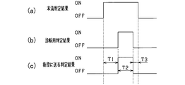
- FIG. 2A shows a determination result by mainstream determination processing
- FIG. 2B shows a determination result by diagnostic determination processing
- FIG. 2C shows a determination result sent from the operation restriction unit 25 to the control processing unit 26.
- the mainstream determination result is diagnosed as abnormal, and an OFF determination is sent to the control processing unit 26.
- the mainstream determination result matches the determination result for diagnosis. This is because the systematic failure in the mainstream determination process has been recovered.
- the mainstream determination result is diagnosed as normal, and an ON determination that is the mainstream determination result is sent to the control processing unit 26. Then, after the main stream ON determination continues during the period T2 and the period T3, the main stream ON determination is switched to the OFF determination. The main ON determination is switched to the OFF determination because the duration of the ON determination is ended. While the mainstream determination result continues to be ON during the period T3, the diagnosis determination result is OFF. This is because the target was lost despite the presence of the target. Therefore, in the period T3, the mainstream determination result is diagnosed as abnormal, and an OFF determination is sent to the control processing unit 26. That is, in the period T3, the mainstream determination process is inhibited by the diagnosis determination process.
- the operation diagnosis unit 24 has the function of the invalid unit 24a.
- the invalidation unit 24a invalidates the diagnosis process by the operation diagnosis unit 24 for a predetermined time after the operation diagnosis unit 24 determines that the determination result by the operation determination unit 23 is normal.
- This predetermined time is a time assuming at least the time until the host vehicle stops.
- the operation restricting unit 25 transmits the determination result of the operation determining unit 23 to the control processing unit 26 during the invalid period in which the diagnosis process is invalidated.
- the diagnosis processing is intended to prevent the automatic brake from malfunctioning due to an error in the mainstream determination result. Therefore, it is sufficient for the diagnosis processing to be able to diagnose the timing at which the determination result to be sent to the control processing unit 26 is switched from the OFF determination to the ON determination.
- FIGS. 2 (a), 2 (b), and 2 (c) are diagrams of determination results when an invalid period is provided.
- the diagnosis determination process is valid for a period T4 from the time point when the diagnosis determination result is switched from OFF determination to ON determination and the main ON determination result is diagnosed as normal.
- the period T4 may be one control cycle, for example.
- the determination process for diagnosis is invalid in the period T5. That is, the period T5 is an invalid period of the diagnostic process.
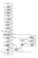
- This processing procedure is repeatedly executed for each target by the ECU 20 for each target with respect to the automatic brake among the functions of the PCS.
- this control cycle may be the same as or different from the predetermined cycle of the radar device 13 and the in-vehicle camera device 12.
- the first detection information is received from the radar device 13 and the first position is acquired (S10).
- 2nd detection information is received from the vehicle-mounted camera apparatus 12, and a 2nd position is acquired (S11).
- various detection information is received from the vehicle sensors 11, and vehicle conditions, such as a vehicle speed and a yaw rate, are acquired (S12).
- an FSN calculation process is performed using the first detection information and the first position acquired in S10 and the second detection information and the second position acquired in S11, and the relative position and the relative speed of the target are calculated. (S13).
- the system state of the PCS is detected, and it is determined whether or not there is a problem in the system state (S14).
- the collision risk is estimated for the target existing at the front position in the region Re, and it is determined whether or not the automatic brake is to be operated (S15).
- the collision risk is estimated for a target existing outside the area Re in front of the traveling direction of the host vehicle, and it is determined whether or not to activate the automatic brake ( S16).
- the determination result in S15 and the determination result in S16 are integrated to calculate the determination result (S17).
- the process proceeds to S23.
- the determination result in the determination process for the previous diagnosis is OFF determination, when the determination process for diagnosis is in an invalid state as in the period T5 in FIG. 3, and the main determination as in the period T7 in FIG. This is a case where the result is OFF determination and a case where the mainstream determination result is ON determination but is incorrect as in the period T1 in FIG.
- S23 it is determined whether it is within the invalid period. That is, it is determined whether the invalid state count is started and the invalid state count is equal to or shorter than the invalid period set in S20. If the count of the invalid state is not started or the count exceeds the invalid period, it is determined that the invalid period is not exceeded (S23: NO), and whether or not the automatic brake is activated by the determination process for diagnosis. Determine (S24).
- the invalid state count is started and the invalid state count is equal to or less than the set invalid period, it is determined that it is within the invalid period (S23: YES), and the invalid state count is increased ( S28), the mainstream determination result is transmitted to the control processing unit 26 (S29), and this process is terminated.
- the vehicle control device and vehicle control method according to the first embodiment described above have the following effects.
- Whether or not to operate the automatic brake is determined by a diagnosis determination process that is different from the mainstream determination process, and the mainstream determination result is diagnosed.
- the mainstream determination result is diagnosed as abnormal.
- the mainstream determination result is transmitted to the control processing unit 26.
- the mainstream determination result is converted into the control process. It is not transmitted to the unit 26. Therefore, when an error occurs in the mainstream determination result, the main brake determination result is not transmitted to the control processing unit 26, and thus the automatic brake is not activated. Therefore, the erroneous operation of the automatic brake can be appropriately suppressed.
- the purpose of the diagnosis process is to prevent malfunction of the automatic brake due to systematic failure, so it is necessary to diagnose whether the determination result is normal or not for the determination result that the automatic brake is not operated. There is no. Therefore, only when it is determined that the automatic brake is to be operated, by diagnosing the main determination result, unnecessary calculation processing can be omitted and the calculation load can be reduced.
- the target in the region Re and the target outside the region Re have different moving directions and moving speeds that increase the risk of collision with the vehicle. Therefore, it is determined whether or not the automatic brake is to be operated by a different determination process between the target in the region Re and the target outside the region Re in the forward direction. Thereby, the action
- the main judgment result diagnosis process is invalidated for a predetermined time after the diagnosis is normal.
- the mainstream determination process is not likely to be hindered by the diagnosis determination process.
- the vehicle control device according to the second embodiment will be described focusing on differences from the vehicle control device according to the first embodiment.
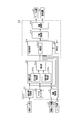
- the structure of ECU20 which is a vehicle control apparatus which concerns on this embodiment is demonstrated with reference to FIG.
- the ECU 20 according to the present embodiment has the function of the maintenance unit 28.
- the maintenance unit 28 holds the automatic brake in an operating state after the automatic brake is activated and the host vehicle is stopped.
- the host vehicle may collide with the target, and the vehicle sensors 11, the in-vehicle camera device 12, and the radar device 13 may have failed. Therefore, if the determination process for diagnosis is performed in a state where the automatic brake is in the hold state, there is a possibility that the diagnosis of the mainstream determination result is erroneous. Therefore, when the automatic brake is maintained in the operating state by the maintaining unit 28, that is, when the automatic brake is in the hold state, the invalid part 24a gives priority to the automatic brake hold process and performs the operation diagnosis. The diagnosis process by the unit 24 is invalidated. Then, the operation restricting unit 25 transmits the determination result of the operation determining unit 23 to the control processing unit 26 while the automatic brake is in the hold state.
- FIG. 6C shows the determination result for diagnosis when there is no hold function.
- the brake hold determination result in FIG. 6B is ON determination when in the hold state, and OFF determination when not in the hold state.
- the mainstream determination result is diagnosed as abnormal due to a systematic failure occurring in the mainstream determination process (OFF in the period T11 in FIG. 6D).
- the mainstream determination result and the diagnosis determination result are ON determination, the mainstream determination result is diagnosed as normal, and the automatic brake is in an operating state.
- the automatic brake is activated and the host vehicle is stopped, the automatic brake is in the hold state during the period T13, and the diagnosis determination process is in an invalid state.
- the mainstream ON determination is sent to the control processing unit 26.
- This processing procedure is repeatedly executed for each target by the ECU 20 for each target with respect to the automatic brake among the functions of the PCS. Note that this control cycle may be the same as or different from the predetermined cycle of the radar device 13 and the in-vehicle camera device 12.
- the processing from S40 to S48 of the processing procedure for operating the automatic brake of the vehicle control method according to the second embodiment is performed in S10 of the flowchart of FIG. 4 in the vehicle control method performed by the vehicle control device according to the first embodiment. Processes similar to the processes of S18. Subsequently, it is determined whether or not the automatic brake is in a hold state (S49). When the automatic brake is in the hold state (S49: YES), the mainstream determination result, that is, the automatic brake ON determination is transmitted to the control processing unit 26 (S50), and this process is terminated.
- the vehicle control device and the vehicle control method of the present invention are not limited to the first and second embodiments described above.
- the following modifications are also included in the scope of the invention.
- the processing of S19 to S23, S28 and S29 in the flowchart shown in FIG. 4 may be omitted.
- the determination process for diagnosis is not limited to determining whether the main automatic brake is ON, but may be performed when determining whether the main brake assist is ON or when determining whether the main alarm is ON. In this case, what is necessary is just to perform the flowchart shown in FIG.4 and FIG.7 about each of brake assistance and a warning. At that time, in the processing of S18 and S48, it may be determined whether or not the brake assist or warning is ON determination.
- diagnosis determination processing may be performed regardless of whether the main determination result is ON determination or not. In this case, in the diagnosis determination process, it is not assumed that the main determination result is ON determination as an operating condition.
- the operation determination unit 23 may not perform the PCS operation determination separately for the target in the region Re and the target outside the region Re in the forward direction of travel. That is, the processing of S15 to S17 shown in FIG. 4 may be a single processing, and similarly, the processing of S45 to S47 shown in FIG. 7 may be a single processing.
- the position information of the target detected by the in-vehicle camera device 12 may be used instead of the position information of the target detected by the radar device 13. That is, the operation diagnosis unit 24 activates each function of the PCS based on both the position of the target by the FSN calculation process and the position information of the target detected by the in-vehicle camera device 12 not through the FSN calculation process. It may be determined whether or not.
- the function of the integration unit 23c may be included in the operation diagnosis unit 24.
- the host vehicle is driven by the driver, but the ECU 20 can be similarly applied to a vehicle that is automatically driven by a vehicle control ECU or the like.
- the PCS function only needs to be an automatic brake function.
- the brake device 31 is provided as the safety device, and the alarm device 32 may not be provided.
- Each function of the ECU 20 is not limited to the ECU 20 that is a processing device (computer) mounted on the vehicle, but may be realized by a processing device such as a portable information terminal possessed by the driver. Further, the operation determination unit 23 and the operation diagnosis unit 24 may be realized by different processing devices.
Landscapes
- Engineering & Computer Science (AREA)
- Radar, Positioning & Navigation (AREA)
- Remote Sensing (AREA)
- Physics & Mathematics (AREA)
- General Physics & Mathematics (AREA)
- Mechanical Engineering (AREA)
- Transportation (AREA)
- Automation & Control Theory (AREA)
- Computer Networks & Wireless Communication (AREA)
- Human Computer Interaction (AREA)
- Electromagnetism (AREA)
- Combustion & Propulsion (AREA)
- Chemical & Material Sciences (AREA)
- Traffic Control Systems (AREA)
- Regulating Braking Force (AREA)
Priority Applications (1)
| Application Number | Priority Date | Filing Date | Title |
|---|---|---|---|
| US15/578,646 US10723347B2 (en) | 2015-06-02 | 2016-04-15 | Vehicle control device and vehicle control method |
Applications Claiming Priority (2)
| Application Number | Priority Date | Filing Date | Title |
|---|---|---|---|
| JP2015112075A JP6365421B2 (ja) | 2015-06-02 | 2015-06-02 | 車両制御装置、及び車両制御方法 |
| JP2015-112075 | 2015-06-02 |
Publications (1)
| Publication Number | Publication Date |
|---|---|
| WO2016194491A1 true WO2016194491A1 (ja) | 2016-12-08 |
Family
ID=57440461
Family Applications (1)
| Application Number | Title | Priority Date | Filing Date |
|---|---|---|---|
| PCT/JP2016/062096 Ceased WO2016194491A1 (ja) | 2015-06-02 | 2016-04-15 | 車両制御装置、及び車両制御方法 |
Country Status (3)
| Country | Link |
|---|---|
| US (1) | US10723347B2 (enExample) |
| JP (1) | JP6365421B2 (enExample) |
| WO (1) | WO2016194491A1 (enExample) |
Cited By (4)
| Publication number | Priority date | Publication date | Assignee | Title |
|---|---|---|---|---|
| CN109421740A (zh) * | 2017-08-28 | 2019-03-05 | 通用汽车环球科技运作有限责任公司 | 用于监测自主车辆的方法和装置 |
| CN109720313A (zh) * | 2018-12-29 | 2019-05-07 | 江西与德电子技术有限公司 | 一种控制方法、装置、设备及存储介质 |
| CN110341722A (zh) * | 2019-07-25 | 2019-10-18 | 百度在线网络技术(北京)有限公司 | 自动驾驶车辆的行驶方法和装置、电子设备、可读介质 |
| CN111055829A (zh) * | 2018-10-15 | 2020-04-24 | 现代自动车株式会社 | 自动驾驶控制装置、具有该装置的车辆及控制该装置的方法 |
Families Citing this family (6)
| Publication number | Priority date | Publication date | Assignee | Title |
|---|---|---|---|---|
| CN107571856A (zh) * | 2017-09-08 | 2018-01-12 | 合肥永烨信息科技有限公司 | 一种车辆交通紧急情况自动调整系统 |
| WO2019158204A1 (en) * | 2018-02-15 | 2019-08-22 | Toyota Motor Europe | Control method for a vehicle, computer program, non-transitory computer-readable medium, and automated driving system |
| CN111086508B (zh) | 2018-10-24 | 2024-11-22 | 罗伯特·博世有限公司 | 自动躲避或减轻碰撞的方法及控制系统、存储介质和汽车 |
| US11422229B2 (en) * | 2019-02-01 | 2022-08-23 | Preco Electronics, LLC | Display and alarm for vehicle object detection radar |
| JP7380171B2 (ja) * | 2019-12-17 | 2023-11-15 | 株式会社デンソー | 運転支援装置および運転支援プログラム |
| CN112249010A (zh) * | 2020-11-03 | 2021-01-22 | 浙江大华汽车技术有限公司 | 车辆自动紧急制动的控制方法和装置及存储介质 |
Citations (3)
| Publication number | Priority date | Publication date | Assignee | Title |
|---|---|---|---|---|
| JP2003015743A (ja) * | 2001-06-27 | 2003-01-17 | Denso Corp | 車両の自動運転システム |
| JP2007226680A (ja) * | 2006-02-24 | 2007-09-06 | Toyota Motor Corp | 物体検出装置 |
| JP2009271766A (ja) * | 2008-05-08 | 2009-11-19 | Hitachi Ltd | 自動車用障害物検知装置 |
Family Cites Families (6)
| Publication number | Priority date | Publication date | Assignee | Title |
|---|---|---|---|---|
| JP4528457B2 (ja) | 2001-03-15 | 2010-08-18 | 日立オートモティブシステムズ株式会社 | 自動車用ブレーキ装置及びその制御方法 |
| JP3960317B2 (ja) * | 2004-03-03 | 2007-08-15 | 日産自動車株式会社 | 車両用運転操作補助装置および車両用運転操作補助装置を備えた車両 |
| US20060091653A1 (en) * | 2004-11-04 | 2006-05-04 | Autoliv Asp, Inc. | System for sensing impending collision and adjusting deployment of safety device |
| JP4639930B2 (ja) | 2005-04-26 | 2011-02-23 | 日産自動車株式会社 | 冗長系システム及びその故障診断方法 |
| DE102012211391A1 (de) * | 2012-07-02 | 2014-01-02 | Continental Teves Ag & Co. Ohg | Verfahren und System zur Informationsnutzung |
| JP6036724B2 (ja) * | 2014-02-17 | 2016-11-30 | トヨタ自動車株式会社 | 車両周辺状況認識装置および車両制御装置 |
-
2015
- 2015-06-02 JP JP2015112075A patent/JP6365421B2/ja active Active
-
2016
- 2016-04-15 US US15/578,646 patent/US10723347B2/en active Active
- 2016-04-15 WO PCT/JP2016/062096 patent/WO2016194491A1/ja not_active Ceased
Patent Citations (3)
| Publication number | Priority date | Publication date | Assignee | Title |
|---|---|---|---|---|
| JP2003015743A (ja) * | 2001-06-27 | 2003-01-17 | Denso Corp | 車両の自動運転システム |
| JP2007226680A (ja) * | 2006-02-24 | 2007-09-06 | Toyota Motor Corp | 物体検出装置 |
| JP2009271766A (ja) * | 2008-05-08 | 2009-11-19 | Hitachi Ltd | 自動車用障害物検知装置 |
Cited By (4)
| Publication number | Priority date | Publication date | Assignee | Title |
|---|---|---|---|---|
| CN109421740A (zh) * | 2017-08-28 | 2019-03-05 | 通用汽车环球科技运作有限责任公司 | 用于监测自主车辆的方法和装置 |
| CN111055829A (zh) * | 2018-10-15 | 2020-04-24 | 现代自动车株式会社 | 自动驾驶控制装置、具有该装置的车辆及控制该装置的方法 |
| CN109720313A (zh) * | 2018-12-29 | 2019-05-07 | 江西与德电子技术有限公司 | 一种控制方法、装置、设备及存储介质 |
| CN110341722A (zh) * | 2019-07-25 | 2019-10-18 | 百度在线网络技术(北京)有限公司 | 自动驾驶车辆的行驶方法和装置、电子设备、可读介质 |
Also Published As
| Publication number | Publication date |
|---|---|
| JP2016224794A (ja) | 2016-12-28 |
| US10723347B2 (en) | 2020-07-28 |
| JP6365421B2 (ja) | 2018-08-01 |
| US20180162389A1 (en) | 2018-06-14 |
Similar Documents
| Publication | Publication Date | Title |
|---|---|---|
| JP6365421B2 (ja) | 車両制御装置、及び車両制御方法 | |
| CN108156822B (zh) | 车辆控制装置,以及车辆控制方法 | |
| CN107615092B (zh) | 车辆控制装置以及车辆控制方法 | |
| CN107615356B (zh) | 车辆控制装置以及车辆控制方法 | |
| US10854081B2 (en) | Driving assistance device and driving assistance method | |
| JP6136714B2 (ja) | 車両制御装置 | |
| CN109311474B (zh) | 行人保护中的自主制动故障管理 | |
| JP6527369B2 (ja) | 車両制御装置、及び車両制御方法 | |
| US10668919B2 (en) | Object detection apparatus and object detection method | |
| EP3007149B1 (en) | Driving assistance device for vehicles and onboard computer | |
| US20180118202A1 (en) | Vehicle control apparatus and vehicle control method | |
| US10861337B2 (en) | Vehicle control apparatus and vehicle control method | |
| CN108137007B (zh) | 车辆控制装置以及车辆控制方法 | |
| JP2016037203A (ja) | 運転支援装置 | |
| JP2019002689A (ja) | 物標検出装置 | |
| WO2017094891A1 (ja) | 物体検出装置及び物体検出方法 | |
| JP6462610B2 (ja) | 横断判定装置 |
Legal Events
| Date | Code | Title | Description |
|---|---|---|---|
| 121 | Ep: the epo has been informed by wipo that ep was designated in this application |
Ref document number: 16802928 Country of ref document: EP Kind code of ref document: A1 |
|
| WWE | Wipo information: entry into national phase |
Ref document number: 15578646 Country of ref document: US |
|
| NENP | Non-entry into the national phase |
Ref country code: DE |
|
| 122 | Ep: pct application non-entry in european phase |
Ref document number: 16802928 Country of ref document: EP Kind code of ref document: A1 |