WO2016192009A1 - 一种组合移相器及多频天线网络系统 - Google Patents
一种组合移相器及多频天线网络系统 Download PDFInfo
- Publication number
- WO2016192009A1 WO2016192009A1 PCT/CN2015/080493 CN2015080493W WO2016192009A1 WO 2016192009 A1 WO2016192009 A1 WO 2016192009A1 CN 2015080493 W CN2015080493 W CN 2015080493W WO 2016192009 A1 WO2016192009 A1 WO 2016192009A1
- Authority
- WO
- WIPO (PCT)
- Prior art keywords
- phase shifter
- signal
- output
- combined
- substrate
- Prior art date
Links
Images


Classifications
-
- H—ELECTRICITY
- H01—ELECTRIC ELEMENTS
- H01Q—ANTENNAS, i.e. RADIO AERIALS
- H01Q3/00—Arrangements for changing or varying the orientation or the shape of the directional pattern of the waves radiated from an antenna or antenna system
- H01Q3/26—Arrangements for changing or varying the orientation or the shape of the directional pattern of the waves radiated from an antenna or antenna system varying the relative phase or relative amplitude of energisation between two or more active radiating elements; varying the distribution of energy across a radiating aperture
- H01Q3/30—Arrangements for changing or varying the orientation or the shape of the directional pattern of the waves radiated from an antenna or antenna system varying the relative phase or relative amplitude of energisation between two or more active radiating elements; varying the distribution of energy across a radiating aperture varying the relative phase between the radiating elements of an array
- H01Q3/34—Arrangements for changing or varying the orientation or the shape of the directional pattern of the waves radiated from an antenna or antenna system varying the relative phase or relative amplitude of energisation between two or more active radiating elements; varying the distribution of energy across a radiating aperture varying the relative phase between the radiating elements of an array by electrical means
- H01Q3/36—Arrangements for changing or varying the orientation or the shape of the directional pattern of the waves radiated from an antenna or antenna system varying the relative phase or relative amplitude of energisation between two or more active radiating elements; varying the distribution of energy across a radiating aperture varying the relative phase between the radiating elements of an array by electrical means with variable phase-shifters
-
- H—ELECTRICITY
- H01—ELECTRIC ELEMENTS
- H01P—WAVEGUIDES; RESONATORS, LINES, OR OTHER DEVICES OF THE WAVEGUIDE TYPE
- H01P1/00—Auxiliary devices
- H01P1/18—Phase-shifters
-
- H—ELECTRICITY
- H01—ELECTRIC ELEMENTS
- H01P—WAVEGUIDES; RESONATORS, LINES, OR OTHER DEVICES OF THE WAVEGUIDE TYPE
- H01P1/00—Auxiliary devices
- H01P1/18—Phase-shifters
- H01P1/184—Strip line phase-shifters
-
- H—ELECTRICITY
- H01—ELECTRIC ELEMENTS
- H01Q—ANTENNAS, i.e. RADIO AERIALS
- H01Q1/00—Details of, or arrangements associated with, antennas
- H01Q1/12—Supports; Mounting means
- H01Q1/22—Supports; Mounting means by structural association with other equipment or articles
- H01Q1/24—Supports; Mounting means by structural association with other equipment or articles with receiving set
- H01Q1/241—Supports; Mounting means by structural association with other equipment or articles with receiving set used in mobile communications, e.g. GSM
- H01Q1/246—Supports; Mounting means by structural association with other equipment or articles with receiving set used in mobile communications, e.g. GSM specially adapted for base stations
-
- H—ELECTRICITY
- H01—ELECTRIC ELEMENTS
- H01Q—ANTENNAS, i.e. RADIO AERIALS
- H01Q3/00—Arrangements for changing or varying the orientation or the shape of the directional pattern of the waves radiated from an antenna or antenna system
- H01Q3/26—Arrangements for changing or varying the orientation or the shape of the directional pattern of the waves radiated from an antenna or antenna system varying the relative phase or relative amplitude of energisation between two or more active radiating elements; varying the distribution of energy across a radiating aperture
- H01Q3/30—Arrangements for changing or varying the orientation or the shape of the directional pattern of the waves radiated from an antenna or antenna system varying the relative phase or relative amplitude of energisation between two or more active radiating elements; varying the distribution of energy across a radiating aperture varying the relative phase between the radiating elements of an array
- H01Q3/32—Arrangements for changing or varying the orientation or the shape of the directional pattern of the waves radiated from an antenna or antenna system varying the relative phase or relative amplitude of energisation between two or more active radiating elements; varying the distribution of energy across a radiating aperture varying the relative phase between the radiating elements of an array by mechanical means
-
- H—ELECTRICITY
- H01—ELECTRIC ELEMENTS
- H01Q—ANTENNAS, i.e. RADIO AERIALS
- H01Q5/00—Arrangements for simultaneous operation of antennas on two or more different wavebands, e.g. dual-band or multi-band arrangements
- H01Q5/30—Arrangements for providing operation on different wavebands
- H01Q5/307—Individual or coupled radiating elements, each element being fed in an unspecified way
- H01Q5/342—Individual or coupled radiating elements, each element being fed in an unspecified way for different propagation modes
- H01Q5/357—Individual or coupled radiating elements, each element being fed in an unspecified way for different propagation modes using a single feed point
- H01Q5/364—Creating multiple current paths
- H01Q5/371—Branching current paths
-
- H—ELECTRICITY
- H01—ELECTRIC ELEMENTS
- H01Q—ANTENNAS, i.e. RADIO AERIALS
- H01Q1/00—Details of, or arrangements associated with, antennas
- H01Q1/12—Supports; Mounting means
- H01Q1/125—Means for positioning
-
- H—ELECTRICITY
- H01—ELECTRIC ELEMENTS
- H01Q—ANTENNAS, i.e. RADIO AERIALS
- H01Q1/00—Details of, or arrangements associated with, antennas
- H01Q1/12—Supports; Mounting means
- H01Q1/125—Means for positioning
- H01Q1/1257—Means for positioning using the received signal strength
-
- H—ELECTRICITY
- H01—ELECTRIC ELEMENTS
- H01Q—ANTENNAS, i.e. RADIO AERIALS
- H01Q1/00—Details of, or arrangements associated with, antennas
- H01Q1/12—Supports; Mounting means
- H01Q1/22—Supports; Mounting means by structural association with other equipment or articles
- H01Q1/24—Supports; Mounting means by structural association with other equipment or articles with receiving set
- H01Q1/241—Supports; Mounting means by structural association with other equipment or articles with receiving set used in mobile communications, e.g. GSM
- H01Q1/242—Supports; Mounting means by structural association with other equipment or articles with receiving set used in mobile communications, e.g. GSM specially adapted for hand-held use
- H01Q1/243—Supports; Mounting means by structural association with other equipment or articles with receiving set used in mobile communications, e.g. GSM specially adapted for hand-held use with built-in antennas
-
- H—ELECTRICITY
- H01—ELECTRIC ELEMENTS
- H01Q—ANTENNAS, i.e. RADIO AERIALS
- H01Q21/00—Antenna arrays or systems
- H01Q21/24—Combinations of antenna units polarised in different directions for transmitting or receiving circularly and elliptically polarised waves or waves linearly polarised in any direction
Definitions
- the invention relates to the technical field of communication, in particular to a combined phase shifter and a multi-frequency antenna network system.
- the phase shifter is the core component of the base station antenna.
- the phase shifter currently developed can not only adjust the phase, but also adjust the amplitude, so that the direction of the base station antenna in the spatial transmission direction is adjusted to meet the flexible adjustment coverage of different users. Regional needs.
- the excellent performance of the phase shifter not only affects the gain, pattern, isolation and other indicators of the antenna, but also affects the size and cost.
- a cavity phase shifter including a housing 1 in which a cavity is disposed, a substrate 3 located in the cavity, a conductor 4 disposed on the substrate, and activities disposed on both sides of the substrate 3.
- the conductor 4 shown may be a movable medium as a substrate or air as a substrate; the movable movable medium 2 shown includes upper and lower portions, and the conductor 4 is fixed in the movable medium 2.
- the movable medium 2 is free to slide in the wiring direction of the conductor 4, changing the position and coverage area of the covered conductor 4, thus affecting the change in the dielectric constant of the propagated signal. That is, the phase of the output signal changes to achieve phase shifting.
- FIG 2 shows the network connection diagram of the current traditional multi-frequency antenna (Note: CMB represents the combiner), the phase shifter and the combiner are designed separately, the cables are more, the wiring is complicated, and the single-sided base station antenna is integrated. More and more frequency bands, this kind of network connection is already difficult to meet the demand
- the invention provides a combined phase shifter multi-frequency antenna network system for reducing the cable of the multi-frequency antenna network system and facilitating the setting of the multi-frequency antenna network system.
- a combined phase shifter comprising at least two stacked phase shifters, and each phase shifter has a different frequency band, wherein each phase shifter comprises a signal layer and Phase a component that slides the signal layer and is used to change a phase of an output end of the signal layer, wherein an output end of the signal layer is provided with a filter circuit;
- the output ends of the filter circuits corresponding to the at least two phase shifters are connected by conductors and output through a common output terminal.
- the signal line layer includes an input end, a power splitter connected to the input end, and a first output end connected to the power splitter and Two signal transmission lines, wherein each signal transmission line is connected with at least one branch transmission line, and each branch transmission line is connected with a filter circuit, and the filter circuit is connected with the output end.
- the common output end has a U-shaped snap ring structure or a through hole structure
- the conductor card is mounted on the U-shaped snap ring structure or through-hole structure and signal connection.
- the two signal transmission lines are symmetrically distributed on both sides of the power splitter.
- phase shifter is a physical phase shifter
- the component is a swing arm
- a signal layer of the phase shifter is attached to the substrate.
- the number of the phase shifters is two, and the signal layers of the two phase shifters are respectively attached On opposite sides of the substrate.
- the first possible implementation manner of the first aspect, the second possible implementation manner of the first aspect, and the third possible implementation manner of the first aspect, in a sixth possible implementation manner There is further included a housing in which a chamber corresponding to each phase shifter is disposed, and each chamber is provided with a substrate for carrying a signal layer of a phase shifter in the chamber.
- the substrate is a substrate made of plastic or ceramic material.
- a partition is disposed between adjacent cavities, and the partition is provided with a pass for the conductor through hole.
- a card slot for chucking the phase shifter is disposed in each cavity.
- a multi-frequency antenna network system comprising the combined phase shifter of any of the above.
- a combined phase shifter in a first aspect, is provided, and in a second aspect, a multi-frequency antenna network system is provided, which integrates outputs of two phase shifters of different frequencies by using a conductor, and at the same time,
- the combined phase shifter provided by the embodiment does not need to use an additional combiner, which reduces the used device compared with the prior art, and also reduces the use of cables in the multi-frequency antenna network system, thereby facilitating layout. It facilitates the setting of the multi-frequency antenna network system, and in addition, facilitates the layout of the whole machine, reduces the weight of the whole machine, and saves costs.
- the combined phase shifter provided by the embodiment of the invention can also improve the antenna gain and optimize the direction parameter.
- Figure 1 is a cross-sectional view of a prior art combined phase shifter
- FIG. 2 is a system diagram of a multi-frequency antenna network system in the prior art
- FIG. 3 is an exploded perspective view of a combined phase shifter according to an embodiment of the present invention.
- FIG. 4 is a cross-sectional view of a combined phase shifter according to an embodiment of the present invention.
- FIG. 5 is a schematic structural diagram of a signal line layer of a combined phase shifter according to an embodiment of the present invention.
- FIG. 6 is a schematic structural diagram of another signal line layer according to an embodiment of the present disclosure.
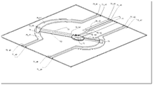
- FIG. 7 is a schematic structural diagram of another combined phase shifter according to an embodiment of the present invention.
- FIG. 8 is a side view of another combined phase shifter according to an embodiment of the present invention.
- FIG. 9 is a schematic structural diagram of another combined phase shifter according to an embodiment of the present invention.
- FIG. 10 is a system diagram of a multi-frequency antenna network system according to an embodiment of the present invention.
- Embodiments of the present invention provide a combined phase shifter including at least two stacked phase shifters, and each of the phase shifters has different frequency bands, wherein each phase shifter includes a signal layer and a member sliding relative to the signal layer and for changing a phase of an output end of the signal layer, wherein an output end of the signal layer is provided with a filter circuit;
- An output end of the filter circuit corresponding to the at least two phase shifters is connected through a conductor and passes through a A common output output.
- the output ends of the phase shifters of two different frequencies are integrated and output by using a conductor, and the combined phase shifter provided by the embodiment does not need to use an additional combiner, and the prior art
- the use of the cable in the multi-frequency antenna network system is reduced, and the layout is facilitated, thereby facilitating the setting of the multi-frequency antenna network system, and in addition, facilitating the layout of the whole machine and reducing the weight of the whole machine. ,save costs.
- the combined phase shifter provided by the embodiment of the invention can also improve the antenna gain and optimize the direction parameter.
- the combined phase shifter further includes a housing in which a chamber corresponding to each phase shifter is disposed.
- a substrate is provided within the chamber for carrying a signal layer of a phase shifter within the chamber.
- the housing has two layers of cavities, one phase shifter is disposed in each cavity, and the two phase shifters are different phase shifters for different frequencies.
- FIG. 3 shows an exploded view of the combined phase shifter provided in this embodiment
- FIG. 4 shows the combined phase shifter provided in this embodiment. Sectional view.
- a partition is disposed between adjacent cavities in the casing 10, and the partition is provided with a through hole for the conductor to be bored. That is, the cavity in the housing 10 is divided into the first cavity 11 and the second cavity 12 by the spacer, and the first cavity 11 and the second cavity 12 are respectively provided with the first phase shifter and the second cavity Phase shifter.
- the first phase shifter and the second phase shifter each include: a signal line layer disposed on the substrate; a dielectric layer symmetrically disposed on both sides of the signal line layer and slidable relative to the signal line layer (ie, in the embodiment) A component for changing the output of the signal layer).
- the substrate and the signal line layer can be formed by using a printed circuit, that is, the signal line is printed on the substrate to form a printed circuit board, or a substrate made of a plastic or ceramic material can also be used.
- a signal line layer is formed on the substrate by other means of fabricating the circuit.
- the first phase shifter includes a first substrate 30 and is disposed on the first substrate 30.
- the first signal line layer 20 is symmetrically disposed on the first dielectric layer 40 on both sides of the first signal line layer 20.
- the second phase shifter includes a second substrate 31 and a second signal line layer 21 disposed on the second substrate 31, and is symmetrically disposed on the two sides of the second signal line layer 21
- the first signal line layer 20 and the second signal line layer 21 have corresponding output ends, and the corresponding output ends are connected by conductors, so that the signals of the phase shifters of two different frequencies are integrated and sent out.
- a card slot for the card phase shifter is disposed in each cavity. That is, the side walls of the first cavity 11 and the second cavity 12 are respectively provided with card slots, and the two card slots are respectively used for fixing the first substrate 30 of the first phase shifter and the second phase of the second phase shifter.
- the substrate 31 is such that the first phase shifter and the second phase shifter can be stably disposed in the first cavity 11 and the second cavity 12.
- the signal line layer comprises an input end, a power splitter connected to the input end, a first output end connected to the power splitter and two signal transmission lines, wherein each signal transmission line is connected with at least one branch transmission line, each The branch transmission line is connected to a filter circuit, and the filter circuit is connected to the output end. That is, the output end of the signal line layer is connected to the power splitter through the filter circuit and the connection line, and in actual setting, the number of output ends can be set as needed, that is, by setting different branch transmission lines and correspondingly set filters, it can be set. Different outputs.
- the output terminal of the filter circuit of one of the plurality of phase shifters is connected to the common output terminal.
- FIG. 5 shows the structure of the signal line layer when two layers of signal lines are used.
- the phase shifting principle of the phase shifter of the present invention is the same as that of the prior art phase shifter:
- the signal is divided into three by the power splitter 20a2: one way is transmitted to the signal transmission line 20a3, and one signal is transmitted to the signal.
- the transmission line 20a5 is transmitted to the output of the first output terminal 62, and the signal is output through the first output terminal 62.
- the signal is transmitted along the signal transmission line 20a3 to the branch signal transmission line 20a4, and then transmitted to the filter.
- the wave circuit 20b1 wherein the circuit of the filter circuit 20b1 has a filtering function, is transmitted to the conductor post 51 disposed at the output end, and is output through the common output terminal 61; the signal propagates along the signal transmission line 20a5 to the signal transmission line 20a6, and is transmitted to the signal transmission line 20a6 to The filter circuit 20b2, similarly, the filter circuit 20b2 also has a filtering function, which is transmitted to the conductor post 50 disposed in the output end via the filter circuit 20b2, and the conductor post 50 propagates the signal to the common output terminal 60, and the signal is output through the common output terminal 60. .
- another signal of different frequency bands is input from 21a1, and one of the power splitters 21a2 is three, one is transmitted to the signal transmission line 21a3, one is transmitted to the signal transmission line 21a5, and one is transmitted to the first output terminal 63, and the signal is first.
- the output terminal 63 is connected to the cable output; the signal is transmitted along the signal transmission line 21a3 to the signal transmission line 21a4, and the signal is transmitted along the signal transmission line 21a4 to the filter circuit 21b1 having the filtering function, after being filtered by the filter circuit 21b1, and then transmitted to the common output terminal 61;
- the 21a5 is transmitted to the signal transmission line 21a6, transmitted to the filter circuit 21b2 having the filtering function via the signal transmission line 21a6, and finally outputted through the common output terminal 60.
- Each of the above output terminals (60, 61, 62, 63) is connected to the antenna radiating unit.
- the conductors 50, 51 have the function of connecting the output ends of the phase shifters of different frequency bands, and can turn on the signals: the filter circuit 20b1, the filter circuit 21b1 and the conductor 51 form a combiner; the filter circuit 20b2, the filter circuit 21b2 and the conductor 50 form a combiner .
- both sides of each signal transmission line correspond to a pair of dielectric layers sliding relative to the signal line layer.
- the first dielectric layer 40 is distributed on both sides of the signal line 20 and is slidable along the signal lines 20a3, 20a5, thereby changing the phase of the signals on the 20a3, 20a5.
- the second dielectric layer 41 is distributed on both sides of the signal line 21 and is slidable along the signal lines 21a3, 21a5, thereby changing the phase of the signals on 21a3, 21a5.
- one signal transmission line corresponds to one branch signal transmission line
- the formed output ports are the first output terminals 62, 63, and the common output terminals 60, 61.
- FIG. 6 shows the structure of another signal line layer.
- Fig. 6 is a view showing the structure of a two-branch signal transmission line.
- each of the signal line layers shown in FIG. 6 corresponds to two branch signal output lines.
- the signal transmission line 21a5 corresponds to two branch signal transmission lines 21a6 and 21a7, each branch signal transmission line corresponds to one filter circuit, and each filter circuit corresponds to one output terminal; the signal transmission line 21a3 corresponds to two branch signal transmission lines 21a4.
- each branch signal transmission line corresponds to a filter circuit, and each filter circuit has an output end.
- the output ends of the branch signal transmission lines 20a6 and 21a6 are connected by the conductor 50 and outputted at the common output terminal 60, and the corresponding output ends of the branch signal transmission lines 20a7 and 21a7 are connected by the conductor 52 and passed through the common output terminal.
- the output terminals corresponding to the branch signal lines 20a4 and 21a4 are connected by the conductor 51, and are output through the common output terminal 61.
- the output terminal 65 connected to the branch signal transmission line 20a8 and the output terminal 64 connected to the branch signal transmission line 21a8 are not connected by conductors (may also be connected by conductors, and outputted by the common output terminal) . Therefore, the combined phase shifter formed by the signal line layer shown in Figure 6 has six output ports (60, 61, 62, 63, 64, 65, 66).
- FIG. 5 and FIG. 6 only show two specific structures of the signal line layer provided by this embodiment.
- the signal line layer provided in this embodiment is not limited to the specific ones shown in FIG. 5 and FIG. 6 above. Structures, other variations are also applicable in this embodiment.
- the common output end When the conductor is connected to the signal line layer, specifically, the common output end has a U-shaped snap ring structure or a through hole structure, and the conductor is carded in the U-shaped snap ring structure or the through hole structure and connected in signal.
- the conductor When the conductor is specifically mounted, the conductor is directly attached to the above-mentioned U-shaped snap ring structure or through hole structure. With the above structure, the connection of the conductor to the two signal line layers is facilitated.
- the two signal transmission lines are symmetrically distributed on both sides of the power splitter. That is, the signal transmission line is set by using a symmetrical structure.
- the setting of the branch signal line is also set in a symmetrical manner, thereby facilitating the setting of the signal transmission line and the branch signal transmission line, avoiding interaction between the lines, and improving the signal line. The overall beauty of the layer.
- the combined phase shifter provided by the embodiment of the present invention is not limited to the structure of the two-layer phase shifter listed in the above specific embodiment, and a phase shifter of three layers, four layers and the like may be disposed in the cavity of the housing 10, The principle is similar to the structure of the combined phase shifter listed in the above specific embodiment, and will not be further described herein.
- phase shifter provided in this embodiment is not limited to the specific phase shifting of the medium described above, and may be a phase shifter of other principles, such as: the phase shifter is a physical phase shifter, and the component is a swing arm, and The signal layer of the phase shifter is attached to the substrate.
- FIG. 7, FIG. 8 and FIG. 9. The specific structure is shown in FIG. 7, FIG. 8 and FIG. 9.
- two phase shifters are taken as an example.
- the number of phase shifters is two, and the signals of the two phase shifters are The layers are respectively attached to opposite sides of the substrate.
- FIG. 7, FIG. 8, and FIG. 9 are physical displacement devices of the prior art: signal lines 82 and 83 are attached to both sides of the substrate 80 (82, 83 is a signal line of two phase shifters on both sides of the substrate), and a metal ground (also referred to as a reference surface) 81 is formed in the middle of the substrate 80 to form a microstrip line: the working principle is described below.
- the signal is input through the input terminal 70 and transmitted to the power splitter 70_b1: one is divided into two, one is transmitted through the transmission line 70_b2, and output through the output terminal 70_a5; the other is transmitted through the transmission line 70_b3, coupled to the swing arm 73: two along the swing arm 73
- the signal is transmitted to the coupling rectangular piece 70_b6 via the transmission line 70_b4, and the signal is coupled to the curved line 74 by 70_b6: the signal is transmitted in two directions 70_b7, 70_b8 along the curved line 74: respectively through the output terminals 70_a1, 70_a2 Output.
- the swing arm (the member for changing the phase of the output end of the signal layer in the present embodiment) can be swung in the arc transmission direction with the rotating shaft 75 as the axis: thus the coupling rectangular piece 70_b6 is on the curved line 74.
- the ends 70_a2, 70_a4 also change the phase of the output by swinging the swing arm.
- the above is the working principle of the phase shifter of the scheme.
- phase shifter signal line 83 on the other side of the substrate 80 is the same as the above: that is, the signal is input from the input terminal 71, and is output through 71_a1, 71_a2, 71_a3, 71_a4, and 71_a5, and the phase of the output end is changed by swinging the swing arm 72 to realize shifting. Phase function, detailed process is no longer described.
- the combined phase shifter signal lines 82, 83 are attached to the substrate 80.
- the substrate and the signal line layer can be fabricated by using a printed circuit, that is, the signal line is printed on the substrate to form a printing.
- the circuit substrate, or a substrate made of a plastic or ceramic material may also be used.
- the signal layer is formed on the substrate by other means of fabricating the circuit; or the signal line is realized by sheet metal, and the substrate is not required.
- the branch nodes 91, 92, 93, 94 ie, filter circuits having the filtering function integrated at the output end are connected through the conductors (such as 90) to form a combined circuit, and the output terminals are outputted to form a kind.
- Combine phase shifters The frequency of the input signals of the upper and lower layers of the substrate is different.
- phase shifting principle of the phase shifter provided in this embodiment may be the phase shifting of the cavity structure in the embodiment, or may be a phase shifter of other implementation forms, such as implementation.
- the physical phase shifter can be implemented as long as the phase of the output port can be changed.
- an embodiment of the present invention further provides a multi-frequency antenna network system, where the multi-frequency antenna network system includes the combined phase shifter of any of the above.
- the output ends of the phase shifters of two different frequencies are integrated and output by using a conductor, and the combined phase shifter provided by the embodiment does not need to use an additional combiner, and the prior art
- the use of the cable in the multi-frequency antenna network system is reduced, and the layout is facilitated, thereby facilitating the setting of the multi-frequency antenna network system, and in addition, facilitating the layout of the whole machine and reducing the weight of the whole machine. ,save costs.
- the combined phase shifter provided by the embodiment of the invention can also improve the antenna gain and optimize the direction parameter.
Landscapes
- Engineering & Computer Science (AREA)
- Computer Networks & Wireless Communication (AREA)
- Waveguide Switches, Polarizers, And Phase Shifters (AREA)
- Variable-Direction Aerials And Aerial Arrays (AREA)
- Details Of Aerials (AREA)
Priority Applications (10)
| Application Number | Priority Date | Filing Date | Title |
|---|---|---|---|
| EP15893669.0A EP3291362B1 (de) | 2015-06-01 | 2015-06-01 | Kombinierter phasenschieber und mehrfrequenzantennennetzwerksystem |
| PCT/CN2015/080493 WO2016192009A1 (zh) | 2015-06-01 | 2015-06-01 | 一种组合移相器及多频天线网络系统 |
| EP19219779.6A EP3703181B1 (de) | 2015-06-01 | 2015-06-01 | Kombinierter phasenschieber und mehrbandantennennetzwerksystem |
| CN201580072395.9A CN107710498B (zh) | 2015-06-01 | 2015-06-01 | 一种组合移相器及多频天线网络系统 |
| CN201911397385.9A CN111029776B (zh) | 2015-06-01 | 2015-06-01 | 一种天线 |
| ES15893669T ES2779530T3 (es) | 2015-06-01 | 2015-06-01 | Desfasador combinado y sistema de red de antena multifrecuencia |
| MX2017015406A MX2017015406A (es) | 2015-06-01 | 2015-06-01 | Desfasador combinado y sistema de red de antena multi-banda. |
| EP24164777.5A EP4411984A2 (de) | 2015-06-01 | 2015-06-01 | Kombinierter phasenschieber und mehrbandantennennetzwerksystem |
| US15/820,921 US10498028B2 (en) | 2015-06-01 | 2017-11-22 | Combined phase shifter and multi-band antenna network system |
| US16/418,900 US10573964B2 (en) | 2015-06-01 | 2019-05-21 | Combined phase shifter and multi-band antenna network system |
Applications Claiming Priority (1)
| Application Number | Priority Date | Filing Date | Title |
|---|---|---|---|
| PCT/CN2015/080493 WO2016192009A1 (zh) | 2015-06-01 | 2015-06-01 | 一种组合移相器及多频天线网络系统 |
Related Child Applications (1)
| Application Number | Title | Priority Date | Filing Date |
|---|---|---|---|
| US15/820,921 Continuation US10498028B2 (en) | 2015-06-01 | 2017-11-22 | Combined phase shifter and multi-band antenna network system |
Publications (1)
| Publication Number | Publication Date |
|---|---|
| WO2016192009A1 true WO2016192009A1 (zh) | 2016-12-08 |
Family
ID=57441695
Family Applications (1)
| Application Number | Title | Priority Date | Filing Date |
|---|---|---|---|
| PCT/CN2015/080493 WO2016192009A1 (zh) | 2015-06-01 | 2015-06-01 | 一种组合移相器及多频天线网络系统 |
Country Status (6)
| Country | Link |
|---|---|
| US (2) | US10498028B2 (de) |
| EP (3) | EP4411984A2 (de) |
| CN (2) | CN111029776B (de) |
| ES (1) | ES2779530T3 (de) |
| MX (1) | MX2017015406A (de) |
| WO (1) | WO2016192009A1 (de) |
Cited By (3)
| Publication number | Priority date | Publication date | Assignee | Title |
|---|---|---|---|---|
| CN108270076A (zh) * | 2017-01-03 | 2018-07-10 | 和硕联合科技股份有限公司 | 平面天线模块及电子装置 |
| CN109904597A (zh) * | 2017-12-11 | 2019-06-18 | 华为技术有限公司 | 一种馈电设备、天线及电子设备 |
| WO2022067609A1 (zh) * | 2020-09-30 | 2022-04-07 | 华为技术有限公司 | 多频段相控阵和电子设备 |
Families Citing this family (13)
| Publication number | Priority date | Publication date | Assignee | Title |
|---|---|---|---|---|
| CN109802234B (zh) * | 2019-01-30 | 2023-09-29 | 京信通信技术(广州)有限公司 | 基站天线及移相馈电装置 |
| CN110661102B (zh) * | 2019-09-29 | 2021-05-07 | 华南理工大学 | 移相装置及基站天线 |
| CN112864548A (zh) * | 2019-11-12 | 2021-05-28 | 康普技术有限责任公司 | 腔体移相器以及基站天线 |
| CN111106417B (zh) * | 2019-12-18 | 2024-08-16 | 摩比科技(深圳)有限公司 | 一种移相器及基站天线 |
| CN111063970A (zh) * | 2019-12-27 | 2020-04-24 | 华南理工大学 | 微波器件及天线 |
| CN111342174B (zh) * | 2020-03-12 | 2021-03-30 | 华南理工大学 | 滤波移相器及天线 |
| CN114447542A (zh) * | 2020-10-30 | 2022-05-06 | 康普技术有限责任公司 | 滑动件、移相器和基站天线 |
| CN116529953A (zh) * | 2020-12-21 | 2023-08-01 | 华为技术有限公司 | 天线及通讯设备 |
| CN113540794B (zh) * | 2021-07-01 | 2022-08-19 | 华南理工大学 | 移相装置、天线及基站 |
| CN116031651A (zh) * | 2021-10-27 | 2023-04-28 | 康普技术有限责任公司 | 移相器组件和基站天线 |
| CN116207500A (zh) * | 2021-11-30 | 2023-06-02 | 康普技术有限责任公司 | 多频带移相器组件、多频带天线系统和基站天线 |
| CN114497930B (zh) * | 2022-01-06 | 2023-06-23 | 京信通信技术(广州)有限公司 | 合路移相装置与天线 |
| CN114883764B (zh) * | 2022-05-23 | 2024-02-02 | 中国人民解放军63660部队 | 一种宽频带高功率微波移相器 |
Citations (5)
| Publication number | Priority date | Publication date | Assignee | Title |
|---|---|---|---|---|
| JP2001196804A (ja) * | 2000-01-14 | 2001-07-19 | Sumitomo Electric Ind Ltd | 可変移相器及びフェーズドアレイアンテナ |
| CN2838051Y (zh) * | 2005-11-07 | 2006-11-15 | 杨斌 | 连续可调同轴移相器 |
| CN101694897A (zh) * | 2009-10-30 | 2010-04-14 | 网拓(上海)通信技术有限公司 | 移相器 |
| CN103474724A (zh) * | 2013-09-24 | 2013-12-25 | 上海无线电设备研究所 | 高性能可调双频移相器及其双频通带调整方法 |
| WO2015013063A1 (en) * | 2013-07-26 | 2015-01-29 | Radio Frequency Systems Inc. | Devices for providing phase adjustments in multi-element antenna arrays and related methods |
Family Cites Families (46)
| Publication number | Priority date | Publication date | Assignee | Title |
|---|---|---|---|---|
| US2432026A (en) * | 1943-09-20 | 1947-12-02 | Hazeltine Research Inc | Position-indicating arrangement |
| US4599585A (en) * | 1982-03-01 | 1986-07-08 | Raytheon Company | N-bit digitally controlled phase shifter |
| US7663502B2 (en) * | 1992-05-05 | 2010-02-16 | Intelligent Technologies International, Inc. | Asset system control arrangement and method |
| GB2235590B (en) | 1989-08-21 | 1994-05-25 | Radial Antenna Lab Ltd | Planar antenna |
| US5278574A (en) | 1991-04-29 | 1994-01-11 | Electromagnetic Sciences, Inc. | Mounting structure for multi-element phased array antenna |
| RU2053549C1 (ru) * | 1992-01-24 | 1996-01-27 | Северо-Западный Заочный Политехнический Институт | Устройство для моделирования системы радиолокационного зондирования тонких немагнитных слоев |
| US6449469B1 (en) * | 1999-03-01 | 2002-09-10 | Visteon Global Technologies, Inc. | Switched directional antenna for automotive radio receivers |
| KR100399605B1 (ko) * | 2001-08-22 | 2003-09-29 | 학교법인 포항공과대학교 | 공기-유전체 샌드위치 구조 및 이를 이용한 유전체공진기, 대역 통과 및 소거 필터, 동조 변위기 그리고위상 배열 안테나 |
| US7301422B2 (en) * | 2005-06-02 | 2007-11-27 | Andrew Corporation | Variable differential phase shifter having a divider wiper arm |
| US7701115B2 (en) * | 2007-05-01 | 2010-04-20 | Panasonic Corporation | Drive unit |
| JP4320348B2 (ja) * | 2007-05-30 | 2009-08-26 | 電気興業株式会社 | 結合回路 |
| CN201181729Y (zh) * | 2007-12-12 | 2009-01-14 | 西安海天天线科技股份有限公司 | 用于电调天线的移相器 |
| US7907096B2 (en) | 2008-01-25 | 2011-03-15 | Andrew Llc | Phase shifter and antenna including phase shifter |
| JP4650561B2 (ja) * | 2008-12-02 | 2011-03-16 | 住友電気工業株式会社 | 移相器 |
| CN101567667B (zh) * | 2009-04-24 | 2011-10-19 | 福建三元达通讯股份有限公司 | 增强型模拟预失真线性化功率放大器 |
| CN101645524B (zh) * | 2009-07-13 | 2013-02-13 | 电子科技大学 | 一种基于螺旋慢波线的小型化电调智能天线移相器 |
| CN102082326B (zh) * | 2009-11-26 | 2014-03-19 | 中国移动通信集团公司 | 一种支持异系统独立电调的智能天线设备及方法 |
| US20110183624A1 (en) * | 2010-01-28 | 2011-07-28 | Thiagarajar College Of Engineering | Devices and Methods for Phase Shifting a Radio Frequency (RF) Signal for a Base Station Antenna |
| EP2612440A4 (de) * | 2010-08-30 | 2014-02-19 | Physical Devices Llc | Einstellbare filtervorrichtungen und verfahren dafür |
| CN102055049B (zh) * | 2010-10-19 | 2013-07-17 | 电子科技大学 | 一种集总元件360度射频模拟电调移相器 |
| CN102176524B (zh) * | 2011-03-28 | 2014-03-26 | 京信通信系统(中国)有限公司 | 同轴介质移相系统、移相器及移相驱动装置 |
| CN202121034U (zh) * | 2011-03-28 | 2012-01-18 | 京信通信系统(中国)有限公司 | 同轴介质移相系统、移相器及移相驱动装置 |
| KR101230507B1 (ko) * | 2011-05-23 | 2013-02-06 | 주식회사 굿텔 | 마주보는 접지면을 구비한 위상가변기 |
| FR2977381B1 (fr) * | 2011-06-30 | 2014-06-06 | Alcatel Lucent | Dephaseur et repartiteur de puissance |
| CN102544733B (zh) * | 2012-01-31 | 2014-04-02 | 广东博纬通信科技有限公司 | 一种基站电调天线相位连续线性可变的移相器 |
| CN202523820U (zh) * | 2012-04-23 | 2012-11-07 | 华为技术有限公司 | 移相器以及天线 |
| JP5619069B2 (ja) * | 2012-05-11 | 2014-11-05 | 株式会社東芝 | アクティブフェーズドアレイアンテナ装置 |
| CN102738553B (zh) * | 2012-06-29 | 2014-08-27 | 武汉虹信通信技术有限责任公司 | 一种高性能的排气管电调天线的机械结构 |
| CN202712432U (zh) * | 2012-07-13 | 2013-01-30 | 良特电子科技(东莞)有限公司 | 一种天线移相器 |
| CN202839907U (zh) * | 2012-10-22 | 2013-03-27 | 华为技术有限公司 | 移相器和具有移相器的天线 |
| RU125775U1 (ru) * | 2012-10-25 | 2013-03-10 | Федеральное Государственное Унитарное Предприятие "Научно-Производственное Предприятие "Пульсар" | Активный фазовращатель (варианты) |
| CN203180015U (zh) * | 2012-12-18 | 2013-09-04 | 张家港保税区国信通信有限公司 | 超宽带一体化空气带线移相器 |
| CN103107387B (zh) * | 2013-02-08 | 2015-03-25 | 华为技术有限公司 | 具有滤波元件的移相器以及滤波元件和天线 |
| CN103779635B (zh) * | 2013-12-31 | 2016-04-27 | 北京长峰广播通讯设备有限责任公司 | 一种大功率传输线移相器 |
| US9444151B2 (en) * | 2014-01-10 | 2016-09-13 | Commscope Technologies Llc | Enhanced phase shifter circuit to reduce RF cables |
| CN203910971U (zh) * | 2014-02-27 | 2014-10-29 | 京信通信技术(广州)有限公司 | 移相系统 |
| KR101415540B1 (ko) * | 2014-04-04 | 2014-07-04 | 주식회사 선우커뮤니케이션 | 대역별 가변틸트 안테나 장치 |
| CN203813002U (zh) * | 2014-04-11 | 2014-09-03 | 深圳国人通信股份有限公司 | 一种电调天线的移相器 |
| CN103928762B (zh) * | 2014-04-15 | 2016-01-27 | 华为技术有限公司 | 天线设备 |
| CN203826558U (zh) * | 2014-04-30 | 2014-09-10 | 广东晖速通信技术有限公司 | 一种4g天线的一体化馈电网络 |
| CN104051821B (zh) * | 2014-05-23 | 2019-03-01 | 京信通信技术(广州)有限公司 | 介质移相器 |
| CN104181521B (zh) * | 2014-06-24 | 2016-09-14 | 合肥工业大学 | 一种发射多频载波的高距离分辨率雷达 |
| CN104090268B (zh) * | 2014-06-26 | 2016-08-24 | 中国电子科技集团公司第二十研究所 | 一种基于真时延技术的折返型微波组件 |
| CN104362438B (zh) * | 2014-10-30 | 2017-04-26 | 西安欣创电子技术有限公司 | 一种整体式大扫描角波束合成移相器 |
| CN204144434U (zh) * | 2014-11-10 | 2015-02-04 | 广东盛华德通讯科技股份有限公司 | 独立电调智能天线 |
| CN204348871U (zh) * | 2014-12-30 | 2015-05-20 | 电联工程技术股份有限公司 | 一种小型微带移相器 |
-
2015
- 2015-06-01 CN CN201911397385.9A patent/CN111029776B/zh active Active
- 2015-06-01 EP EP24164777.5A patent/EP4411984A2/de active Pending
- 2015-06-01 EP EP15893669.0A patent/EP3291362B1/de active Active
- 2015-06-01 EP EP19219779.6A patent/EP3703181B1/de active Active
- 2015-06-01 CN CN201580072395.9A patent/CN107710498B/zh active Active
- 2015-06-01 MX MX2017015406A patent/MX2017015406A/es active IP Right Grant
- 2015-06-01 WO PCT/CN2015/080493 patent/WO2016192009A1/zh active Application Filing
- 2015-06-01 ES ES15893669T patent/ES2779530T3/es active Active
-
2017
- 2017-11-22 US US15/820,921 patent/US10498028B2/en active Active
-
2019
- 2019-05-21 US US16/418,900 patent/US10573964B2/en active Active
Patent Citations (5)
| Publication number | Priority date | Publication date | Assignee | Title |
|---|---|---|---|---|
| JP2001196804A (ja) * | 2000-01-14 | 2001-07-19 | Sumitomo Electric Ind Ltd | 可変移相器及びフェーズドアレイアンテナ |
| CN2838051Y (zh) * | 2005-11-07 | 2006-11-15 | 杨斌 | 连续可调同轴移相器 |
| CN101694897A (zh) * | 2009-10-30 | 2010-04-14 | 网拓(上海)通信技术有限公司 | 移相器 |
| WO2015013063A1 (en) * | 2013-07-26 | 2015-01-29 | Radio Frequency Systems Inc. | Devices for providing phase adjustments in multi-element antenna arrays and related methods |
| CN103474724A (zh) * | 2013-09-24 | 2013-12-25 | 上海无线电设备研究所 | 高性能可调双频移相器及其双频通带调整方法 |
Cited By (5)
| Publication number | Priority date | Publication date | Assignee | Title |
|---|---|---|---|---|
| CN108270076A (zh) * | 2017-01-03 | 2018-07-10 | 和硕联合科技股份有限公司 | 平面天线模块及电子装置 |
| CN109904597A (zh) * | 2017-12-11 | 2019-06-18 | 华为技术有限公司 | 一种馈电设备、天线及电子设备 |
| US11196183B2 (en) | 2017-12-11 | 2021-12-07 | Huawei Technologies Co., Ltd. | Feeding device, antenna, and electronic device |
| EP4254811A3 (de) * | 2017-12-11 | 2023-11-29 | Huawei Technologies Co., Ltd. | Stromspeisungsvorrichtung, antenne und elektronisches vorrichtung |
| WO2022067609A1 (zh) * | 2020-09-30 | 2022-04-07 | 华为技术有限公司 | 多频段相控阵和电子设备 |
Also Published As
| Publication number | Publication date |
|---|---|
| US20190273317A1 (en) | 2019-09-05 |
| EP3291362A1 (de) | 2018-03-07 |
| EP3291362B1 (de) | 2020-01-15 |
| CN107710498B (zh) | 2020-01-10 |
| CN107710498A (zh) | 2018-02-16 |
| EP3291362A4 (de) | 2018-05-23 |
| EP3703181B1 (de) | 2024-04-10 |
| US20180108990A1 (en) | 2018-04-19 |
| MX2017015406A (es) | 2018-03-01 |
| EP3703181A1 (de) | 2020-09-02 |
| CN111029776A (zh) | 2020-04-17 |
| EP3703181C0 (de) | 2024-04-10 |
| US10573964B2 (en) | 2020-02-25 |
| US10498028B2 (en) | 2019-12-03 |
| EP4411984A2 (de) | 2024-08-07 |
| CN111029776B (zh) | 2021-04-09 |
| ES2779530T3 (es) | 2020-08-18 |
Similar Documents
| Publication | Publication Date | Title |
|---|---|---|
| WO2016192009A1 (zh) | 一种组合移相器及多频天线网络系统 | |
| Rosenberg et al. | A novel frequency-selective power combiner/divider in single-layer substrate integrated waveguide technology | |
| Chu et al. | Dual-mode substrate integrated waveguide filter with flexible response | |
| JP5153866B2 (ja) | 電力分配器 | |
| CN104037475A (zh) | 腔体式微波器件 | |
| KR20120017452A (ko) | 합성 우/좌향 위상-선도/지연 라인들을 이용한 다이플렉서 합성 | |
| Feng et al. | Compact single-/dual-band planar crossovers based on strong coupled lines | |
| WO2018094994A1 (zh) | 电调天线馈电装置及方法 | |
| Yang et al. | Analytical design method and implementation of broadband 4× 4 Nolen matrix | |
| Lin et al. | A new concept and approach for integration of three-state cavity diplexer based on triple-mode resonators | |
| US6900706B2 (en) | Compact balun with rejection filter for 802.11a and 802.11b simultaneous operation | |
| JP2013085075A (ja) | アンテナ給電回路 | |
| WO2015052838A1 (ja) | 減結合回路 | |
| JP4842245B2 (ja) | トリプレクサ回路 | |
| CN115966875A (zh) | 基于多层电路板的微波定向耦合器 | |
| US20230147406A1 (en) | AU and RU having CWG Filters, and BS having the AU or RU | |
| JPH0878916A (ja) | 方向性結合器 | |
| US6791431B2 (en) | Compact balun with rejection filter for 802.11a and 802.11b simultaneous operation | |
| Chen et al. | Investigation of compact balun‐bandpass filter using folded open‐loop ring resonators and microstrip lines | |
| JP5084678B2 (ja) | パワーデバイダ回路とその素子並びにその回路を備えた回路基板及び回路モジュール | |
| JP2017520164A (ja) | マルチプレクサ、およびマルチプレクサを備えるモバイル用通信機器 | |
| TWI757979B (zh) | 電路板 | |
| JP7075079B2 (ja) | バトラーマトリクス回路 | |
| JP3589446B2 (ja) | 電力増幅器 | |
| CN109428143B (zh) | 基于180°理想反相器的三频平衡式耦合器 |
Legal Events
| Date | Code | Title | Description |
|---|---|---|---|
| 121 | Ep: the epo has been informed by wipo that ep was designated in this application |
Ref document number: 15893669 Country of ref document: EP Kind code of ref document: A1 |
|
| WWE | Wipo information: entry into national phase |
Ref document number: MX/A/2017/015406 Country of ref document: MX |
|
| NENP | Non-entry into the national phase |
Ref country code: DE |