WO2016189989A1 - 減速又は増速装置 - Google Patents
減速又は増速装置 Download PDFInfo
- Publication number
- WO2016189989A1 WO2016189989A1 PCT/JP2016/061766 JP2016061766W WO2016189989A1 WO 2016189989 A1 WO2016189989 A1 WO 2016189989A1 JP 2016061766 W JP2016061766 W JP 2016061766W WO 2016189989 A1 WO2016189989 A1 WO 2016189989A1
- Authority
- WO
- WIPO (PCT)
- Prior art keywords
- crown gear
- cam
- tooth
- gear
- crown
- Prior art date
- Legal status (The legal status is an assumption and is not a legal conclusion. Google has not performed a legal analysis and makes no representation as to the accuracy of the status listed.)
- Ceased
Links
Images







Classifications
-
- F—MECHANICAL ENGINEERING; LIGHTING; HEATING; WEAPONS; BLASTING
- F16—ENGINEERING ELEMENTS AND UNITS; GENERAL MEASURES FOR PRODUCING AND MAINTAINING EFFECTIVE FUNCTIONING OF MACHINES OR INSTALLATIONS; THERMAL INSULATION IN GENERAL
- F16H—GEARING
- F16H1/00—Toothed gearings for conveying rotary motion
- F16H1/28—Toothed gearings for conveying rotary motion with gears having orbital motion
- F16H1/32—Toothed gearings for conveying rotary motion with gears having orbital motion in which the central axis of the gearing lies inside the periphery of an orbital gear
-
- F—MECHANICAL ENGINEERING; LIGHTING; HEATING; WEAPONS; BLASTING
- F16—ENGINEERING ELEMENTS AND UNITS; GENERAL MEASURES FOR PRODUCING AND MAINTAINING EFFECTIVE FUNCTIONING OF MACHINES OR INSTALLATIONS; THERMAL INSULATION IN GENERAL
- F16C—SHAFTS; FLEXIBLE SHAFTS; ELEMENTS OR CRANKSHAFT MECHANISMS; ROTARY BODIES OTHER THAN GEARING ELEMENTS; BEARINGS
- F16C19/00—Bearings with rolling contact, for exclusively rotary movement
- F16C19/02—Bearings with rolling contact, for exclusively rotary movement with bearing balls essentially of the same size in one or more circular rows
- F16C19/10—Bearings with rolling contact, for exclusively rotary movement with bearing balls essentially of the same size in one or more circular rows for axial load mainly
-
- F—MECHANICAL ENGINEERING; LIGHTING; HEATING; WEAPONS; BLASTING
- F16—ENGINEERING ELEMENTS AND UNITS; GENERAL MEASURES FOR PRODUCING AND MAINTAINING EFFECTIVE FUNCTIONING OF MACHINES OR INSTALLATIONS; THERMAL INSULATION IN GENERAL
- F16C—SHAFTS; FLEXIBLE SHAFTS; ELEMENTS OR CRANKSHAFT MECHANISMS; ROTARY BODIES OTHER THAN GEARING ELEMENTS; BEARINGS
- F16C33/00—Parts of bearings; Special methods for making bearings or parts thereof
- F16C33/30—Parts of ball or roller bearings
- F16C33/58—Raceways; Race rings
- F16C33/581—Raceways; Race rings integral with other parts, e.g. with housings or machine elements such as shafts or gear wheels
-
- F—MECHANICAL ENGINEERING; LIGHTING; HEATING; WEAPONS; BLASTING
- F16—ENGINEERING ELEMENTS AND UNITS; GENERAL MEASURES FOR PRODUCING AND MAINTAINING EFFECTIVE FUNCTIONING OF MACHINES OR INSTALLATIONS; THERMAL INSULATION IN GENERAL
- F16C—SHAFTS; FLEXIBLE SHAFTS; ELEMENTS OR CRANKSHAFT MECHANISMS; ROTARY BODIES OTHER THAN GEARING ELEMENTS; BEARINGS
- F16C33/00—Parts of bearings; Special methods for making bearings or parts thereof
- F16C33/30—Parts of ball or roller bearings
- F16C33/58—Raceways; Race rings
- F16C33/583—Details of specific parts of races
- F16C33/585—Details of specific parts of races of raceways, e.g. ribs to guide the rollers
-
- F—MECHANICAL ENGINEERING; LIGHTING; HEATING; WEAPONS; BLASTING
- F16—ENGINEERING ELEMENTS AND UNITS; GENERAL MEASURES FOR PRODUCING AND MAINTAINING EFFECTIVE FUNCTIONING OF MACHINES OR INSTALLATIONS; THERMAL INSULATION IN GENERAL
- F16H—GEARING
- F16H1/00—Toothed gearings for conveying rotary motion
- F16H1/28—Toothed gearings for conveying rotary motion with gears having orbital motion
- F16H1/32—Toothed gearings for conveying rotary motion with gears having orbital motion in which the central axis of the gearing lies inside the periphery of an orbital gear
- F16H1/321—Toothed gearings for conveying rotary motion with gears having orbital motion in which the central axis of the gearing lies inside the periphery of an orbital gear the orbital gear being nutating
-
- F—MECHANICAL ENGINEERING; LIGHTING; HEATING; WEAPONS; BLASTING
- F16—ENGINEERING ELEMENTS AND UNITS; GENERAL MEASURES FOR PRODUCING AND MAINTAINING EFFECTIVE FUNCTIONING OF MACHINES OR INSTALLATIONS; THERMAL INSULATION IN GENERAL
- F16H—GEARING
- F16H37/00—Combinations of mechanical gearings, not provided for in groups F16H1/00 - F16H35/00
- F16H37/12—Gearings comprising primarily toothed or friction gearing, links or levers, and cams, or members of at least two of these types
-
- F—MECHANICAL ENGINEERING; LIGHTING; HEATING; WEAPONS; BLASTING
- F16—ENGINEERING ELEMENTS AND UNITS; GENERAL MEASURES FOR PRODUCING AND MAINTAINING EFFECTIVE FUNCTIONING OF MACHINES OR INSTALLATIONS; THERMAL INSULATION IN GENERAL
- F16C—SHAFTS; FLEXIBLE SHAFTS; ELEMENTS OR CRANKSHAFT MECHANISMS; ROTARY BODIES OTHER THAN GEARING ELEMENTS; BEARINGS
- F16C2380/00—Electrical apparatus
- F16C2380/26—Dynamo-electric machines or combinations therewith, e.g. electro-motors and generators
- F16C2380/27—Motor coupled with a gear, e.g. worm gears
-
- F—MECHANICAL ENGINEERING; LIGHTING; HEATING; WEAPONS; BLASTING
- F16—ENGINEERING ELEMENTS AND UNITS; GENERAL MEASURES FOR PRODUCING AND MAINTAINING EFFECTIVE FUNCTIONING OF MACHINES OR INSTALLATIONS; THERMAL INSULATION IN GENERAL
- F16H—GEARING
- F16H2200/00—Transmissions for multiple ratios
- F16H2200/003—Transmissions for multiple ratios characterised by the number of forward speeds
- F16H2200/0043—Transmissions for multiple ratios characterised by the number of forward speeds the gear ratios comprising four forward speeds
-
- F—MECHANICAL ENGINEERING; LIGHTING; HEATING; WEAPONS; BLASTING
- F16—ENGINEERING ELEMENTS AND UNITS; GENERAL MEASURES FOR PRODUCING AND MAINTAINING EFFECTIVE FUNCTIONING OF MACHINES OR INSTALLATIONS; THERMAL INSULATION IN GENERAL
- F16H—GEARING
- F16H48/00—Differential gearings
- F16H48/12—Differential gearings without gears having orbital motion
- F16H48/14—Differential gearings without gears having orbital motion with cams
- F16H48/147—Differential gearings without gears having orbital motion with cams with driven cam followers or balls engaging two opposite cams
-
- F—MECHANICAL ENGINEERING; LIGHTING; HEATING; WEAPONS; BLASTING
- F16—ENGINEERING ELEMENTS AND UNITS; GENERAL MEASURES FOR PRODUCING AND MAINTAINING EFFECTIVE FUNCTIONING OF MACHINES OR INSTALLATIONS; THERMAL INSULATION IN GENERAL
- F16H—GEARING
- F16H53/00—Cams or cam-followers, e.g. rollers for gearing mechanisms
- F16H53/02—Single-track cams for single-revolution cycles; Camshafts with such cams
Definitions
- the present invention relates to a first crown gear, a second crown gear, a tooth facing the first crown gear and a tooth facing the second crown gear so as to be inclined and meshed with the first crown gear and the second crown gear. And a third crown gear having a back-to-back configuration.
- Patent Document 1 discloses a reduction gear including a first crown gear, a second crown gear, and a third crown gear.
- the third crown gear is inclined between the first crown gear and the second crown gear so that the third crown gear meshes with the first crown gear and the third crown gear meshes with the second crown gear. Be placed.
- the third crown gear is rotatably supported by an input shaft having a bent portion. The input shaft causes the third crown gear to make a wave motion so that the meshing position of the first crown gear and the third crown gear and the meshing position of the third crown gear and the second crown gear move in the circumferential direction.
- the first crown gear is fixed to the housing, and the second crown gear is connected to the output shaft.
- the third crown gear rotates relative to the first crown gear by the difference in the number of teeth of the third crown gear due to the wave motion of the third crown gear.
- the second crown gear rotates relative to the third crown gear by the difference in the number of teeth.
- the rotational speed of the second crown gear is the sum of the relative rotational speed of the third crown gear with respect to the first crown gear and the relative rotational speed of the second crown gear with respect to the third crown gear.
- the two sets of gears (the first crown gear and the third crown gear, the third crown gear and the second crown gear) are rotated in directions that cancel each other, a large reduction ratio can be obtained, and in a direction that promotes each other. If it is rotated, a small reduction ratio can be obtained.
- the speed reducer described in Patent Document 1 has a problem to be solved due to its structure, and this problem hinders practical application. That is, in this reduction gear, a cross roller ring is used as a bearing that rotatably supports the third crown gear at the bent portion of the input shaft. The reason why the cross roller ring is used is to withstand a large moment acting on the bearing due to a reaction force generated at the meshing portion of the gear.
- the cross roller ring is a bearing in which a large number of rollers are arranged so that the axes of adjacent rollers are perpendicular to each other, and can withstand a large moment.
- the input shaft rotates at a high speed and the output shaft rotates at a low speed.
- a cross roller ring is used as a bearing for an input shaft that rotates at a high speed, the bearing heats up due to the slipping of the roller, or the loss torque increases and efficiency decreases.
- the third crown gear cannot be supported with high rigidity. The same problem occurs even when the input side and the output side of the reduction gear are switched and the reduction gear is used as a speed increase device.
- an object of the present invention is to provide a speed reduction or speed increasing device that can support a third crown gear that performs wave motion with high rigidity and that can also improve efficiency.
- an aspect of the present invention includes a first crown gear, a second crown gear, an opposing tooth facing the first crown gear, and an opposing tooth facing the second crown gear.
- the third crown gear has the first crown, and the third crown gear meshes with the first crown gear, and the third crown gear meshes with the second crown gear.
- a cam portion that is inclined with respect to the gear and the second crown gear and that causes the third crown gear to wave-act so that the meshing portion moves in a circumferential direction, and the cam portion includes the third crown A first cam disposed closer to the first crown gear than the gear, and a second cam disposed closer to the second crown gear than the third crown gear, the first cam and the The third crown gear is sandwiched between the second cam and the first cam is capable of rolling motion between the first cam and the third crown gear.
- Body is interposed, is movably deceleration or speed increasing system is second rolling elements interposed rolling between said second cam the third crown gear.
- the third crown gear that performs wave motion is sandwiched between the first cam and the second cam, the third crown gear can be supported with high rigidity.
- the first and second balls are interposed between the first and second cams and the third crown gear, the third crown gear can be smoothly rotated to improve the efficiency of the speed reduction or speed increasing device. Can be made.
- FIG. 4B the meshing position moves by 90 degrees
- FIGS. 4B to 4C the meshing position moves by 90 degrees.
- FIG. 5 (a) shows a 1st crown gear and a 2nd crown gear
- FIG. b) shows the third crown gear
- FIG. 5 (a) shows a 1st crown gear and a 2nd crown gear
- FIG. b) shows the third crown gear
- FIG. 5 (a) shows a 1st crown gear and a 2nd crown gear
- FIG. b) shows the third crown gear
- FIG. 5 (a) shows a 1st crown gear and a 2nd crown gear
- FIG. b) shows the third crown gear
- gear of the 3rd crown gear of this embodiment shows meshing
- FIG. 10A is a perspective view showing a state where the apex of the moving cone (base of the third crown gear) and the constant cone (base of the first crown gear) are in contact with the bus
- FIG. 10B is the moving cone.
- It is a perspective view which shows no precession. It is a figure which shows the relationship between the point on a moving cone, and a vector. It is a graph which shows the relationship between (theta) and (psi).
- FIG. 16A shows the root curve of the third crown gear
- FIG. 16B shows the root curve of the first crown gear. It is a figure which shows mesh
- FIG. 1 is a cross-sectional perspective view of the speed reducer according to the first embodiment of the present invention
- FIG. 2 is a cross-sectional view. Both show cross-sectional views along the center line of the input shaft.
- the same reference numerals are given to the same components.
- a cylindrical input shaft 5 and a ring-shaped output portion 7 are rotatably accommodated.
- the axis 5a of the input shaft 5 coincides with the axis of the output unit 7.
- the reduction ratio is determined by the number of teeth of the first crown gear 1, the second crown gear 2, and the third crown gear 3 accommodated in the housing 4.
- the configuration of the reduction gear will be described using the direction when the axis 5a of the input shaft 5 and the output unit 7 is arranged in the X direction, that is, the X, Y, and Z directions shown in FIG. To do.
- the housing 4 includes a cylindrical housing main body 4a and a flange 4b fixed to one end of the housing main body 4a in the X direction by a fastening member such as a bolt.
- a through hole 4c for attaching the speed reducer to the counterpart part is opened.
- the output unit 7 is rotatably supported by the flange 4b via, for example, a cross roller 6.
- a ring-shaped raceway 8a having a V-shaped cross section is formed on the inner peripheral surface of the flange 4b.
- a raceway 8b having a ring-shaped cross section facing the raceway 8a is formed on the outer peripheral surface of the output part 7.
- a cross roller 6 is arranged between the raceways 8a and 8b.
- a ring-shaped first crown gear 1 and a ring-shaped second crown gear 2 are arranged such that their axes coincide with the axis 5a of the input shaft 5.
- a third crown gear 3 is disposed between the first crown gear 1 and the second crown gear 2.
- the first crown gear 1 has ring-shaped opposing teeth 1a on the side facing the third crown gear 3 (see also FIG. 3).
- the second crown gear 2 has ring-shaped opposing teeth 2a on the side facing the third crown gear 3 (see also FIG. 3).
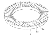
- the third crown gear 3 has a ring-shaped facing tooth 3a facing the first crown gear 1 and a ring-shaped facing tooth 3b facing the second crown gear 2 on the back side (see also FIG. 3).
- Detailed shapes of the opposing teeth 1a, 2a, 3a, 3b of the first crown gear 1, the second crown gear 2, and the third crown gear 3 will be described later.
- the third crown gear 3 is inclined by an angle ⁇ around the Y axis with respect to a plane (YZ plane) orthogonal to the axis 5a (X axis) of the input shaft 5 (see FIG. 2).
- the counter tooth 3a of the third crown gear 3 meshes with the counter tooth 1a of the first crown gear 1 at one place in the circumferential direction, and the counter tooth 3b is the second crown.
- the counter teeth 2a of the gear 2 are meshed at one place in the circumferential direction.
- the first crown gear 1 is fixed to the end of the housing body 4a in the X-axis direction by a fastening member such as a bolt.
- the first crown gear 1 constitutes a part of the housing 4. Thereby, size reduction of the X-axis direction of the reduction gear can be achieved.
- the second crown gear 2 is fixed to the output unit 7 by a fastening member such as a bolt and rotates together with the output unit 7.
- the input shaft 5 passes through the first crown gear 1 and the second crown gear 2.
- the input shaft 5 is rotatably supported by the first crown gear 1 and the second crown gear 2 via bearings 13 and 14.
- the cam portion for wave-moving the third crown gear 3 is attached to the input shaft 5.
- the cam portion includes a first cam 11 disposed on the first crown gear 1 side relative to the third crown gear 3, a second cam 12 disposed on the second crown gear 2 side relative to the third crown gear 3, Is provided.
- the first and second cams 11 and 12 have first and second inclined surfaces 11a and 12a that are parallel to each other and are inclined with respect to the axis 5a. Similar to the third crown gear 3, the first and second inclined surfaces 11a and 12a have an angle ⁇ around the Y axis with respect to a plane (YZ plane) orthogonal to the axis 5a (X axis) of the input shaft 5. Inclined (see FIG. 2).
- the third crown gear 3 is sandwiched between the first cam 11 and the second cam 12 in the axial direction.
- a first ball 15 as a first rolling element is interposed between the first cam 11 and the third crown gear 3 so as to be capable of rolling motion.
- the first inclined surface 11a of the first cam 11 is formed in a circular shape when viewed from the direction of the axis 5a (X axis) (see FIG. 3).
- a circular first ball rolling groove 11a1 is formed on the first inclined surface 11a when viewed from a direction orthogonal to the first inclined surface 11a.
- On the surface of the third crown gear 3 facing the first crown gear 1, a circular third ball rolling groove 3c1 facing the first ball rolling groove 11a1 is formed.
- a large number of first balls 15 are arranged between the first and third ball rolling grooves 11a1 and 3c1.
- the first and third ball rolling grooves 11a1 and 3c1 are designed such that the first ball 15 can receive axial and radial loads.
- the first ball 15 is held by a ring-shaped cage 16.
- the second inclined surface 12a of the second cam 12 is formed with a circular second ball rolling groove 12a1 as viewed from a direction orthogonal to the second inclined surface 12a.
- a circular fourth ball rolling groove 3c2 facing the second ball rolling groove 12a1 is formed on the surface of the third crown gear 3 facing the second crown gear 2.
- a large number of second balls 17 are arranged between the second and fourth ball rolling grooves 12a1 and 3c2.
- the second and fourth ball rolling grooves 12a1 and 3c2 are designed so that the second ball 17 can receive axial and radial loads.
- the second ball 17 is held by a ring-shaped cage 18.
- a preload is applied to the first ball 15 and the second ball 17 so that backlash does not occur in the third crown gear 3 sandwiched between the first and second cams 11 and 12. That is, the first ball 15 is compressed between the first and third ball rolling grooves 11a1 and 3c1, and the second ball 17 is compressed between the second and fourth ball rolling grooves 12a1 and 3c2.
- the third crown gear 3 sandwiched between the first cam 11 and the second cam 12 performs a wave motion (that is, the center of the third crown gear 3).
- the line 3d rotates to draw the trajectory of two cones (this wave motion is called precession).
- the apex of the cone is indicated by point P in FIGS.
- This point P is the center point of the wave motion of the third crown gear 3, and when viewed from the side, the third crown gear 3 swings around the point P like a seesaw. As shown in FIG.
- the center C1 of the circular first ball rolling groove 11a1 is the axis 5a of the input shaft 5 so that the center P of the wave motion of the thick third crown gear 3 can be arranged on the axis.
- the center C2 of the circular second ball rolling groove 12a1 is first from the axis 5a of the input shaft 5 so that the center P of the wave motion of the thick third crown gear 3 can be arranged on the axis 5a. It deviates from the center C1 of the ball rolling groove 11a1 to the opposite side so as to be point symmetric about the point P.
- the meshing location of the first crown gear 1 and the third crown gear 3 and the meshing location of the third crown gear 3 and the second crown gear 2 move in the circumferential direction. .
- the meshing part moves by 90 degrees
- the meshing part moves by 90 degrees.
- the third crown gear 3 rotates about the axis 5a relative to the first crown gear 1 by the difference in the number of teeth of both.
- the second crown gear 2 rotates about the axis 5 a relative to the third crown gear 3 by the difference in the number of teeth of both.
- the rotational speed of the second crown gear 2 is the sum of the relative rotational speed of the third crown gear 3 with respect to the first crown gear 1 and the relative rotational speed of the second crown gear 2 with respect to the third crown gear 3. Become a thing. If the two sets of gears (the first crown gear 1 and the third crown gear 3 and the third crown gear 3 and the second crown gear 2) are rotated in a direction that cancels each other, a large reduction ratio can be obtained. A small reduction ratio can be obtained by rotating in the promoting direction.
- the counter crown 1a of the first crown gear 1 has a fraction of Z1 and the counter crown 3a of the third crown gear 3 meshes with the counter tooth 1a of the first crown gear 1.
- 3 is Z3
- the number of teeth of the counter teeth 2a of the second crown gear 2 is Z4, the reduction ratio GR is given by the following equation (1).
- the overall reduction ratio GR can be obtained from the reduction ratio of the first gear (first crown gear 1 and third crown gear 3) and the reduction ratio of the second gear (third crown gear 3 and second crown gear 2). It is possible to set various reduction ratios from a low reduction ratio to a high reduction ratio.
- the first crown gear 1 serves only as a rotation stop for the third crown gear 3, and the reduction ratio is left to the second gear. If Z1 ⁇ Z2, the first gear has a role of stopping rotation and decelerating. If Z2> Z1 and Z3 ⁇ Z4, or Z2 ⁇ Z1 and Z3> Z4 are set, the first gear and the second gear can be rotated in the direction to cancel each other, and a high reduction ratio can be obtained.
- the input shaft 5 is straight and passes through the first and second cams 11 and 12 and the third crown gear 3.
- the input shaft 5 includes a cylindrical main body portion 5b and a flange 5c.
- the main body 5b is formed with a key groove 5d for preventing rotation on the mating part.
- a hole 5e into which a pin (not shown) for fixing the input shaft 5 and the first and second cams 11 and 12 is inserted is formed in the main body 5b.
- the 1st cam 11 is provided with the cylindrical main-body part 11b inserted in the bearing 13 (refer FIG. 1), and the flange 11c in which the 1st inclined surface 11a is formed.
- the first cam 11 is formed with a hole 11e into which a pin is inserted.
- the 2nd cam 12 is also provided with the cylindrical main-body part 12b inserted in the bearing 14 (refer FIG. 1), and the flange 12c in which the 2nd inclined surface 12a is formed.
- the second cam 12 is also formed with a hole 12e into which a pin is inserted.
- the first cam 11 and the second cam 12 have the same shape. However, the shapes of the first cam 11 and the second cam 12 are not limited to the same.
- the center of gravity of the entire first cam 11 and the second cam 12 is on the axis 5a of the input shaft 5, and even if the first cam 11 and the second cam 12 are rotated at a high speed, they can be prevented from swinging. it can.
- ⁇ Shapes of the teeth of the first to third crown gears (example where the tooth tip portion and the tooth bottom portion are formed from conical side surfaces)>
- FIG. 5A shows a side view of the first crown gear 1 and the second crown gear 2
- FIG. 5B shows a side view of the third crown gear 3.
- the first crown gear 1 has a bevel gear shape and has a conical base.
- corrugated opposing teeth 1a are continuously formed in the circumferential direction.
- the first crown gear 1 has a plurality of tooth tip portions 1a2 arranged radially and a plurality of tooth bottom portions 1a1 arranged radially, alternately in the circumferential direction.
- the tooth bottom 1a1 of the opposing tooth 1a has a concave shape constituted by the side surface of the cone Co1.
- the vertices of the cone Co1 of many tooth bottom portions 1a1 intersect at one point. This intersecting point is the meshing center P.
- the meshing center P is on the axis 5 a of the input shaft 5.
- the tooth tip portion 1a2 of the opposing tooth 1a also has a convex shape constituted by the side surface of the cone Co1 ′ (see the enlarged side view of FIG. 7).
- the vertices of the cone Co1 ′ of the multiple tooth tip portions 1a2 also intersect at the meshing center P.
- the second crown gear 2 has a bevel gear shape and has a conical base. Similar to the first crown gear 1, corrugated opposing teeth 2 a are continuously formed in the circumferential direction on the surface of the ring-shaped second crown gear 2 facing the third crown gear 3.
- the second crown gear 2 has a plurality of tooth tip portions 2a2 arranged radially and a plurality of tooth bottom portions 2a1 arranged radially, alternately in the circumferential direction.
- the bottom portion 2a1 and the tip portion 2a2 of the opposing tooth 2a of the second crown gear 2 are also formed on a part of the side surface of the cone Co2.
- the apex of the tooth bottom portion 2a1 of the opposing tooth 2a of the second crown gear 2 and the cone Co2 of the tooth tip portion 2a2 intersects at one point of the meshing center P.
- the meshing center P of the second crown gear 2 coincides with the meshing center P of the first crown gear 1.
- the third crown gear 3 has a reverse bevel gear shape whose side surface is recessed in a mortar shape.
- the third crown gear 3 is continuously formed in the circumferential direction with an opposing tooth 3a having a waveform facing the first crown gear 1 on the first crown gear 1 side.
- the opposing teeth 3a alternately have a plurality of tooth tip portions 3a2 arranged radially and a plurality of tooth bottom portions 3a1 arranged radially.
- the tooth bottom 3a1 of the opposing tooth 3a is formed on a part of the side surface of the cone Co3.
- the vertices of the cone Co3 of the many tooth bottom portions 3a1 intersect at one point of the meshing center P. As shown in FIG.
- the bottom portion 3 a 1 of the opposed tooth 3 a of the inclined third crown gear 3 meshes with the tooth tip portion 1 a 2 of the opposed tooth 1 a of the first crown gear 1, and therefore the bottom portion of the third crown gear 3.
- the radius of the cone Co3 of 3a1 is larger than the radius of the cone Co1 'of the tooth tip portion 1a2 of the first crown gear 1.
- the tooth tip portion 3a2 of the opposing tooth 3a of the third crown gear 3 is also formed on a part of the side surface of the cone Co3 ′.
- the vertices of the cone Co3 ′ of the multiple tooth tip portions 3a2 intersect at one point of the meshing center P. As shown in FIG.
- the tooth tip portion 3 a 2 of the counter tooth 3 a of the third crown gear 3 meshes with the tooth bottom portion 1 a 1 of the counter tooth 1 a of the first crown gear 1, and therefore the tooth tip portion 3 a 2 of the third crown gear 3.
- the radius of the cone Co3 ′ is smaller than the radius of the cone Co1 of the tooth bottom 1a1 of the first crown gear 1.
- the third crown gear 3 is continuously formed in the circumferential direction with wave-shaped counter teeth 3 b facing the second crown gear 2 on the second crown gear 2 side. Is done.
- the opposing teeth 3b alternately have a plurality of tooth tip portions 3b2 arranged radially and a plurality of tooth bottom portions 3b1 arranged radially.
- the tooth bottom part 3b1 and the tooth tip part 3b2 of the opposing tooth 3b of the third crown gear 3 are formed on part of the side surface of the cone Co4 (only the cone Co4 of the tooth bottom part 3b1 is shown).
- the meshing center P of the counter tooth 3 b of the third crown gear 3 coincides with the mesh center P of the counter tooth 3 a of the third crown gear 3.
- the meshing center P of the third crown gear 3 also coincides with the center P of wave motion of the third crown gear 3 (see FIG. 1).
- the tooth tip portions 1a2, 2a2, 3a2, 3b2 and the tooth bottom portions 1a1, 2a1, 3a1, 3b1 of the first to third crown gears 1 to 3 are configured from conical side surfaces, the first to third crown gears 1 to 3 are formed. 3 is easy to manufacture. However, as shown in the development view of the teeth of the first crown gear 1 and the third crown gear 3 in FIG. 8, when the locus of the tooth tip portion 3a2 (indicated by a circle) of the third crown gear 3 is drawn, the first crown There is a slight gap g between the gear 1 and the third crown gear 3. This gap g may cause an increase in angle transmission error and driving sound.
- the gap g is filled so that the tooth tip portion 3a2 and the tooth bottom portion 1a1 roll completely, and the angle transmission accuracy and quietness are improved.
- the gap g is extremely small, and even if the gap g is not filled, an angle transmission accuracy equivalent to that of the involute tooth profile can be obtained.
- a method for designing the tooth profile curved surfaces of the first crown gear 1 and the third crown gear 3 will be described, but the tooth profile curved surfaces of the second crown gear 2 and the third crown gear 3 can be designed in the same manner. (Overview of design)
- the created tooth profile curve is a single curve, not a surface.
- Tooth tip 1a2,3a2 of the first crown gear 1 and the third crown gear 3 is to be composed of the side surface of the cone, the tooth tip of the reference circle r first crown on c gear 1 and the third crown gear 3 1a2 , 3a2 is a single R arc.
- the tooth bottom curve of the tooth bottom portions 1a1 and 3a1 is a locus drawn by the tooth tip portions 1a2 and 3a2.
- tooth profile curve on the circle r c can be obtained.
- the tooth profile curve is created in the following order.
- the radius of the tooth tip portions 1a2 and 3a2 is determined so that the tooth tip curve (arc) of the tooth tip portions 1a2 and 3a2 and the tooth bottom curve of the tooth bottom portions 1a1 and 3a1 are smoothly connected to each other. (Calculation of the trochoid curve that the tooth tip should pass)
- the third crown gear 3 meshes with the first crown gear 1 while precessing.
- the first crown gear 1 has a conical base that is convex toward the third crown gear 3, and the third crown gear 3 has a cone-shaped base that is mortar-shaped toward the first crown gear 1.
- the tooth surfaces of the first crown gear 1 and the third crown gear 3 are on respective conical bases. Therefore, although congruent tooth profile curves are arranged in the circumferential direction, the tooth profile curves are similar but not congruent in the radial direction. Therefore, defining a certain reference circle r c, determining the tooth profile curve on the reference circle r c.
- the locus drawn by the point P 2 at the time of the dynamic cone is precession a curve should pass through the teeth (trochoid curve).
- FIG. 10B consider a case where the moving cone performs precession without leaving the fixed cone. If this precession is such that the moving cone rotates by - ⁇ around its own axis OH 2 and ⁇ rotates around the constant cone, the point P 1 is ⁇ around OH 1 and the point P 2 is It can be regarded as having rotated ⁇ around OH 2 .
- FIG. 10B consider a case where the moving cone performs precession without leaving the fixed cone. If this precession is such that the moving cone rotates by - ⁇ around its own axis OH 2 and ⁇ rotates around the constant cone, the point P 1 is ⁇ around OH 1 and the point P 2 is It can be regarded as having rotated ⁇ around OH 2 .
- FIG. 10B consider a case where the moving cone performs precession without leaving the fixed cone.
- the vector normalized in parallel with the line segment OH 2 is n
- the vector from the point O to the point P 1 is p 1
- the vector from the point O to the point P 2 is p 2 .
- p 2 can be regarded as a vector obtained by rotating p 1 around n by ⁇
- the p 2 obtained so far can represent a vector representing a curve through which the centers of the tooth tip portions 1a2 and 3a2 of the first crown gear 1 and the third crown gear 3 pass by changing the value of ⁇ .
- a curve through which the center of the tooth tip portion 3a2 of the third crown gear 3 should pass is obtained.
- the moving cone is regarded as the third crown gear 3
- the constant cone is regarded as the first crown gear 1
- the number of teeth is set to z i and z 0 , respectively.
- Equation 5 and 6 are selected according to the characteristics of the gear to be combined and substituting Equation 2 for ⁇ .
- Equation 2 for ⁇ , a curve through which the center of the tooth tip portion passes can be obtained.
- An example of the obtained curve is shown in FIG. 13, the locus vector p 2 draws is trochoidal curve.
- the rotation angles and directions of p1 and p2 are the same as those in FIG. (Calculation of root curve)
- Locus addendum portion 3a2 of the mating gear depicted as shown in FIG. 14 is tooth root curve p 3. That is, the trajectory obtained when you move the trochoidal curve p 2 should pass through the center of the tooth tip 3a2 of the mating gear determined, a circle with a radius of the tooth tip 3a2 of the mating gear on the trochoid curve p 2 Should be calculated.
- the tooth tip radius of the counterpart gear is h k , and this circle is C.
- Equation 7 a vector p 3 representing the tooth bottom curve, among the points when a circle C on p 2, also orthogonal to both p 2 and p 2 of the direction vector Delta] p 2 a vector of up to P 3 points to. Therefore, the relationship of Equation 7 and Equation 8 is established.
- FIG. 16A shows the tooth profile curve (tooth tip curve and root curve) of the third crown gear 3 calculated according to the above
- FIG. 16B shows the tooth profile curve of the first crown gear 1 calculated according to the above.
- (Tooth tip curve and root curve) are shown.
- the radius of the tooth tip curve is determined so that the tooth tip curve and the root curve are smoothly connected.
- the radius of the tooth tip curve is determined on the condition that “the tooth tip curve and the bottom curve have only one contact point”.
- (Equation for tooth tip curve) (Equation for tooth bottom curve) is established, and the value of the tooth tip radius when this has multiple solutions may be found.
- the tooth profile curves of the first crown gear 1 and the third crown gear 3 can be generated.
- FIG. 17 shows the tooth profile curves of the first crown gear 1 and the third crown gear 3 obtained according to the above.
- Black circles in the figure indicate contact points. It can be seen that the first crown gear 1 and the third crown gear 3 are always in contact from the start of contact in (S1) to the end of contact in (S5), and the contact point moves. Since the contact point moves, it can be seen that the first crown gear 1 and the third crown gear 3 roll on each other.
- FIG. 17 shows that the first crown gear 1 moves in the circumferential direction, the third crown gear 3 actually moves in the circumferential direction.
- the bottom portions 1a1 and 3a1 of the first crown gear 1 and the third crown gear 3 are configured from conical side surfaces, and the tooth tip portions 1a2 and 3a2 of the first crown gear 1 and the third crown gear 3 are formed using a trochoid curve. Can also be generated.
- the reference circle r c on the first crown gear 1 and the curve of the tooth bottom 1a1,3a1 the third crown gear 3 an arc of a single R, addendum of the tooth tip 1a2,3a2 with trochoid curve Calculate the curve.
- the teeth of the tooth tip portion 3a2 and the tooth bottom portion 3a1 are obtained.
- Streaks can be helical.
- the phase of the tooth profile curve is different between the outside and the inside of the third crown gear 3.
- the tooth trace of the first crown gear 1 can be similarly helical.
- the logarithmic spiral shown in FIG. 19 can be used for the helical tooth trace.
- the logarithmic helix has a constant angle ⁇ formed with the generatrix of the conical parent body, and can be expressed by the following equation (10).
- a and b are parameters of how to wind the spiral.
- the third crown gear 3 moving in wave motion is sandwiched between the first cam 11 and the second cam 12, the third crown gear 3 can be supported with high rigidity. Further, since the first and second balls 15 and 17 are interposed between the first and second cams 11 and 12 and the third crown gear 3, the third crown gear 3 can be smoothly rotated, and the speed reduction The efficiency of the apparatus can be improved.
- first and second cams 11 and 12 are fixed to the straight input shaft 5 passing through the first and second cams 11 and 12 and the third crown gear 3, the first and second cams 11 and 12 The structure sandwiching the three-crown gear 3 and the assembling property thereof are improved.
- first and second ball rolling grooves 11a1, 12a1 are formed in the first and second cams 11, 12, and the third and fourth ball rolling grooves 3c1, 3c2 are formed in the third crown gear 3.
- the load that can be applied to the first and second balls 15 and 17 can be increased, and the support rigidity of the third crown gear 3 is further improved.
- the center P of the wave motion of the gear 3 can be arranged on the axis 5 a of the input shaft 5.
- the tooth tip portion 1a2 of the first crown gear 1, the tooth tip portion 2a2 of the second crown gear 2, and the tooth tip portions 3a2 and 3b2 of the third crown gear 3 are shown as cones Co1 ′ to Co4 ′ (only Co1 ′ and Co3 ′).
- the tooth root 1a1 of the first crown gear 1, the tooth bottom 2a1 of the second crown gear 2, and the tooth bottoms 3a1 and 3b1 of the third crown gear 3 are conical Co1 to Co4. Since the concave shape is based on the side surface, most of the meshing can be made rolling, and the efficiency of the gear can be improved.
- the “convex shape and concave shape based on the side surface of the cone” means the convex shape and concave shape constituted by the side surfaces of the cones Co1 to Co4, Co1 ′ to Co4 ′, and the third crown gear 3.
- This includes a convex shape and a concave shape generated by using a trochoid curve drawn when the conical base body is rolled along the conical base body of the first crown gear 1 or the second crown gear 2.
- the case where the tooth traces of the tooth tip portions 1a2, 2a2, 3a2, 3b2 and the tooth bottom portions 1a1, 2a1, 3a1, 3b1 having such convex and concave shapes are helical is included.
- first and second balls are interposed between the first and second cams and the third crown gear, but first and second rollers may be interposed.
- the application of the deceleration or speed increasing device of the present invention is not particularly limited, and can be used for various applications such as robot joints, machine tools, automobiles, and the like. Since the reduction ratio can be increased and there is no backlash, it is suitable for high-accuracy positioning and can also be used for semiconductor or liquid crystal manufacturing apparatuses, electron microscopes, and the like. Further, by reversing the input side and the output side, it can be used as a speed increasing device, and can be used as a speed increasing device for a generator having a large input side power, such as a hydroelectric generator.
- First ball (first rolling element), 17 ... First Two balls (second rolling element), C1 ... center of first ball rolling groove (center of first rolling element rolling groove), C2 ... center of second ball rolling groove (second rolling element rolling groove) Center), P ... center of meshing of the first to third crown gears (center of wave motion of the third crown gear), Co1 to Co4, Co1 ', Co3' ... cone
Landscapes
- Engineering & Computer Science (AREA)
- General Engineering & Computer Science (AREA)
- Mechanical Engineering (AREA)
- Retarders (AREA)
- Gears, Cams (AREA)
Abstract
波動運動する第三冠ギヤを高い剛性で支持することができ、効率も向上させることができる減速装置を提供する。 本発明の減速装置は、第一冠ギヤ1と、第二冠ギヤ2と、第一冠ギヤ1に対向する対向歯3aと第二冠ギヤ2に対向する対向歯3bとを背面合わせで持つ第三冠ギヤ3と、第三冠ギヤ3を波動運動させるカム部11,12と、を備える。カム部11,12は、第三冠ギヤ3よりも第一冠ギヤ1側に配置される第一カム11と、第三冠ギヤ3よりも第二冠ギヤ2側に配置される第二カム12と、を有する。第一カム11と第二カム12とで第三冠ギヤ3を挟み、第一カム11と第三冠ギヤ3との間に転がり運動可能に第一転動体15が介在し、第二カム12と第三冠ギヤ13との間に転がり運動可能に第二転動体17が介在する。
Description
本発明は、第一冠ギヤと、第二冠ギヤと、傾斜して第一冠ギヤ及び第二冠ギヤに噛み合うように、第一冠ギヤに対向する歯と第二冠ギヤに対向する歯とを背面合わせで持つ第三冠ギヤと、を備える減速又は増速装置に関する。
特許文献1には、第一冠ギヤ、第二冠ギヤ及び第三冠ギヤを備える減速装置が開示されている。第一冠ギヤと第二冠ギヤとの間には、第三冠ギヤが第一冠ギヤに噛み合い、かつ第三冠ギヤが第二冠ギヤに噛み合うように、第三冠ギヤが傾斜して配置される。第三冠ギヤは、屈曲部を備える入力軸に回転可能に支持される。入力軸は、第一冠ギヤと第三冠ギヤとの噛み合い箇所、及び第三冠ギヤと第二冠ギヤとの噛み合い箇所が円周方向に移動するように第三冠ギヤを波動運動させる。
第一冠ギヤはハウジングに固定され、第二冠ギヤは出力軸に連結される。入力軸を回転させると、第三冠ギヤの波動運動によって、第三冠ギヤが第一冠ギヤに対して両者の歯数差の分だけ相対的に回転する。また、第三冠ギヤの波動運動によって、第二冠ギヤが第三冠ギヤに対して両者の歯数差の分だけ相対的に回転する。第二冠ギヤの回転数は、第一冠ギヤに対する第三冠ギヤの相対的な回転数と、第三冠ギヤに対する第二冠ギヤの相対的な回転数とを合算したものである。二組のギヤ(第一冠ギヤと第三冠ギヤ、第三冠ギヤと第二冠ギヤ)を、互いに打ち消し合う方向に回転させれば、大きな減速比が得られるし、互いに助長する方向に回転させれば、小さな減速比が得られる。
しかし、特許文献1に記載の減速装置には、構造上、解決すべき課題があり、この課題が実用化を妨げている。すなわち、この減速装置においては、入力軸の屈曲部で第三冠ギヤを回転可能に支持する軸受として、クロスローラリングを使用している。クロスローラリングを使用するのは、ギヤの噛み合い箇所に生ずる反力によって軸受に作用する大きなモーメントに耐えるためである。クロスローラリングは、隣接するローラの軸線が互いに直角になるように多数のローラを配列した軸受であり、大きなモーメントに耐えることができる。
しかし、減速装置は、その性質上、入力軸が高速転し、出力軸が低速回転するものである。高速回転する入力軸の軸受としてクロスローラリングを使用すると、ローラの滑りが原因で、軸受が発熱したり、ロストルクが大きくなって効率が低下したりする。これを避けるために、クロスローラの替わりにボールを用いると、第三冠ギヤを高い剛性で支持できない。なお、減速装置の入力側と出力側を入れ替えて、減速装置を増速装置として使用した場合でも、同様な課題が生じる。
そこで、本発明は、波動運動する第三冠ギヤを高い剛性で支持することができ、効率も向上させることができる減速又は増速装置を提供することを目的とする。
上記課題を解決するために、本発明の一態様は、第一冠ギヤと、第二冠ギヤと、前記第一冠ギヤに対向する対向歯と前記第二冠ギヤに対向する対向歯とを背面合わせで持つ第三冠ギヤと、前記第三冠ギヤが前記第一冠ギヤに噛み合い、前記第三冠ギヤが前記第二冠ギヤに噛み合うように、前記第三冠ギヤを前記第一冠ギヤ及び前記第二冠ギヤに対して傾斜させ、かつ噛み合う箇所が円周方向に移動するように前記第三冠ギヤを波動運動させるカム部と、を備え、前記カム部は、前記第三冠ギヤよりも前記第一冠ギヤ側に配置される第一カムと、前記第三冠ギヤよりも前記第二冠ギヤ側に配置される第二カムと、を有し、前記第一カムと前記第二カムとで前記第三冠ギヤを挟み、前記第一カムと前記第三冠ギヤとの間に転がり運動可能に第一転動体が介在し、前記第二カムと前記第三冠ギヤとの間に転がり運動可能に第二転動体が介在する減速又は増速装置である。
本発明によれば、波動運動する第三冠ギヤを第一カムと第二カムとで挟むので、第三冠ギヤを高い剛性で支持することができる。また、第一及び第二カムと第三冠ギヤとの間に第一及び第二ボールが介在するので、第三冠ギヤを円滑に回転させることができ、減速又は増速装置の効率を向上させることができる。
以下、添付図面を参照して、本発明の減速又は増速装置の実施形態を詳細に説明する。ただし、本発明の減速又は増速装置は種々の形態で具体化することができ、本明細書に記載される実施形態に限定されるものではない。本実施形態は、明細書の開示を十分にすることによって、当業者が発明の範囲を十分に理解できるようにする意図をもって提供されるものである。また、本実施形態では、入力軸の回転数を減速して出力軸に伝達する減速装置の例を説明するが、減速装置の入力軸と出力軸を入れ替えることで、減速装置を増速装置としても使用することができる。
<第一の実施形態の減速装置の全体構成>
<第一の実施形態の減速装置の全体構成>
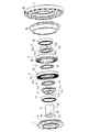
図1は本発明の第一の実施形態の減速装置の断面斜視図であり、図2は断面図である。いずれも入力軸の中心線に沿った断面図を示す。添付の図面及び以下の明細書を通して、同一の構成には同一の符号を附す。ハウジング4には、筒形の入力軸5、リング形の出力部7が回転可能に収容される。入力軸5の軸線5aと出力部7の軸線とは一致する。入力軸5を回転させると、入力軸5の回転数が減速されて出力部7に伝達される。減速比は、ハウジング4に収容される第一冠ギヤ1、第二冠ギヤ2、及び第三冠ギヤ3の歯数によって決定される。なお、以下においては、説明の便宜上、入力軸5及び出力部7の軸線5aをX方向に配置したときの方向、すなわち図1に示すX,Y,Z方向を用いて減速装置の構成を説明する。
ハウジング4は、筒形のハウジング本体4aと、ハウジング本体4aのX方向の一端部にボルト等の締結部材によって固定されるフランジ4bと、を備える。フランジ4bには、減速装置を相手部品に取り付けるための通し孔4cが開けられる。
フランジ4bには、例えばクロスローラ6を介して出力部7が回転可能に支持される。フランジ4bの内周面には、リング形の断面V字のレースウェイ8aが形成される。出力部7の外周面には、レースウェイ8aに対向するリング形の断面V字のレースウェイ8bが形成される。これらのレースウェイ8a,8bの間には、クロスローラ6が配列される。クロスローラ6を使用することで、第二冠ギヤ2と第三冠ギヤ3の噛み合い箇所に生ずる反力によって出力部7に作用するモーメント等の大きな力に耐えることができる。フランジ4bの内側には、クロスローラ6に塵芥等の異物が侵入するのを防止するラビリンスシール9が取り付けられる。
ハウジング本体4aには、リング形の第一冠ギヤ1及びリング形の第二冠ギヤ2が、これらの軸線が入力軸5の軸線5aに一致するように配置される。第一冠ギヤ1と第二冠ギヤ2との間に第三冠ギヤ3が配置される。第一冠ギヤ1は、第三冠ギヤ3に対向する側にリング形の対向歯1aを持つ(図3も参照)。第二冠ギヤ2は、第三冠ギヤ3に対向する側にリング形の対向歯2aを持つ(図3も参照)。第三冠ギヤ3は、第一冠ギヤ1に対向するリング形の対向歯3aと第二冠ギヤ2に対向するリング形の対向歯3bとを背面合わせで持つ(図3も参照)。第一冠ギヤ1、第二冠ギヤ2及び第三冠ギヤ3の対向歯1a,2a,3a,3bの詳細な形状は後述する。
第三冠ギヤ3は、入力軸5の軸線5a(X軸)に直交する平面(YZ平面)に対してY軸の回りに角度αだけ傾く(図2参照)。第三冠ギヤ3が傾くことで、第三冠ギヤ3は、その対向歯3aが第一冠ギヤ1の対向歯1aに円周方向の一箇所で噛み合い、かつその対向歯3bが第二冠ギヤ2の対向歯2aに円周方向の一箇所で噛み合う。
図1に示すように、第一冠ギヤ1は、ボルト等の締結部材によってハウジング本体4aのX軸方向の端部に固定される。第一冠ギヤ1は、ハウジング4の一部を構成する。これにより、減速装置のX軸方向の小型化が図れる。第二冠ギヤ2は、ボルト等の締結部材によって出力部7に固定され、出力部7と一緒に回転する。
第一冠ギヤ1及び第二冠ギヤ2には、入力軸5が貫通する。入力軸5は、軸受13,14を介して第一冠ギヤ1及び第二冠ギヤ2に回転可能に支持される。
入力軸5には、第三冠ギヤ3を波動運動させるカム部が取り付けられる。カム部は、第三冠ギヤ3よりも第一冠ギヤ1側に配置される第一カム11と、第三冠ギヤ3よりも第二冠ギヤ2側に配置される第二カム12と、を備える。第一及び第二カム11,12は、互いに平行で軸線5aに対して傾斜する第一及び第二傾斜面11a,12aを有する。第一及び第二傾斜面11a,12aは、第三冠ギヤ3と同様に、入力軸5の軸線5a(X軸)に直交する平面(YZ平面)に対してY軸の回りに角度αだけ傾斜する(図2参照)。第三冠ギヤ3は、第一カム11と第二カム12とに軸線方向に挟まれる。
図1に示すように、第一カム11と第三冠ギヤ3との間には、転がり運動可能に第一転動体としての第一ボール15が介在する。第一カム11の第一傾斜面11aは、軸線5a(X軸)方向から見て円形に形成される(図3参照)。第一傾斜面11aには、第一傾斜面11aに直交する方向から見て円形の第一ボール転走溝11a1が形成される。第三冠ギヤ3の、第一冠ギヤ1との対向面には、第一ボール転走溝11a1に対向する円形の第三ボール転走溝3c1が形成される。これら第一及び第三ボール転走溝11a1,3c1の間には、多数の第一ボール15が配列される。第一及び第三ボール転走溝11a1,3c1は、第一ボール15が軸方向及び半径方向の荷重を受けられるように設計される。第一ボール15はリング形の保持器16に保持される。
第二カム12と第三冠ギヤ3との間には、転がり運動可能に第二転動体としての第二ボール17が介在する。第二カム12の第二傾斜面12aには、第二傾斜面12aに直交する方向から見て円形の第二ボール転走溝12a1が形成される。第三冠ギヤ3の、第二冠ギヤ2との対向面には、第二ボール転走溝12a1に対向する円形の第四ボール転走溝3c2が形成される。これら第二及び第四ボール転走溝12a1,3c2の間には、多数の第二ボール17が配列される。第二及び第四ボール転走溝12a1,3c2は、第二ボール17が軸方向及び半径方向の荷重を受けられるように設計される。第二ボール17はリング形の保持器18に保持される。
第一及び第二カム11,12で挟まれる第三冠ギヤ3にバックラッシが生じないように、第一ボール15及び第二ボール17には予圧が与えられる。すなわち、第一ボール15は第一及び第三ボール転走溝11a1,3c1の間で圧縮され、第二ボール17は第二及び第四ボール転走溝12a1,3c2の間で圧縮される。
図示しないモータ等の駆動源を用いて、入力軸5を回転させると、第一カム11及び第二カム12に挟まれる第三冠ギヤ3が波動運動する(すなわち、第三冠ギヤ3の中心線3dが2つの円錐の軌跡を描くように回転する。この波動運動は歳差運動と呼ばれる)。円錐の頂点を図1及び図2において点Pで示す。この点Pは第三冠ギヤ3の波動運動の中心点であり、側面から見たとき、第三冠ギヤ3は点Pを中心にシーソーのように揺動する。図2に示すように、厚みのある第三冠ギヤ3の波動運動の中心Pを軸線上に配置できるように、円形の第一ボール転走溝11a1の中心C1は、入力軸5の軸線5aからずれる。同様に、厚みのある第三冠ギヤ3の波動運動の中心Pを軸線5a上に配置できるように、円形の第二ボール転走溝12a1の中心C2は、入力軸5の軸線5aから第一ボール転走溝11a1の中心C1とは点Pを中心にして点対称になるように反対側にずれる。
第三冠ギヤ3の波動運動に伴い、第一冠ギヤ1と第三冠ギヤ3との噛み合い箇所、及び第三冠ギヤ3と第二冠ギヤ2との噛み合い箇所が円周方向に移動する。図4(a)から図4(b)で噛み合い箇所が90度だけ移動し、図4(b)から図4(c)で噛み合い箇所が90度だけ移動する。第三冠ギヤ3の波動運動に伴い、第三冠ギヤ3が第一冠ギヤ1に対して両者の歯数差の分だけ相対的に軸線5aの回りを回転する。また、第二冠ギヤ2が第三冠ギヤ3に対して両者の歯数差の分だけ相対的に軸線5aの回りを回転する。第二冠ギヤ2の回転数は、第一冠ギヤ1に対する第三冠ギヤ3の相対的な回転数と、第三冠ギヤ3に対する第二冠ギヤ2の相対的な回転数とを合算したものになる。二組のギヤ(第一冠ギヤ1と第三冠ギヤ3、第三冠ギヤ3と第二冠ギヤ2)を、互いに打ち消し合う方向に回転させれば、大きな減速比が得られるし、互いに助長する方向に回転させれば、小さな減速比が得られる。
第一冠ギヤ1の対向歯1aの端数をZ1,第一冠ギヤ1の対向歯1aに噛み合う第三冠ギヤ3の対向歯3aの端数をZ2、第二冠ギヤ2に噛み合う第三冠ギヤ3の対向歯3bの端数をZ3、第二冠ギヤ2の対向歯2aの歯数をZ4とすると、減速比GRは以下の式1で与えられる。

例えば、Z1=40、Z2=41、Z3=51、Z4=50とすると、減速比は200である。Z1=50、Z2=49、Z3=50、Z4=50とすると、減速比は50である。全体の減速比GRは、第一ギヤ(第一冠ギヤ1と第三冠ギヤ3)の減速比と第二ギヤ(第三冠ギヤ3と第二冠ギヤ2)の減速比から求めることができ、低い減速比から高い減速比まで多様な減速比を設定することができる。
Z1=Z2とすると、第一冠ギヤ1は第三冠ギヤ3の回転止めのみの役割を持ち、減速比は第二ギヤに委ねられる。Z1≠Z2とすると、第一ギヤは回転止め及び減速の役割を持つ。また、Z2>Z1かつZ3<Z4、又はZ2<Z1かつZ3>Z4に設定すれば、第一ギヤ及び第二ギヤを互いに打ち消し合う方向に回転させることができ、高い減速比が得られる。
図3を参照しつつ、入力軸5、第一及び第二カム11,12の詳細な構造を説明する。入力軸5は、真直であり、第一及び第二カム11,12、並びに第三冠ギヤ3を貫通する。図3に示すように、入力軸5は筒形の本体部5bと、フランジ5cと、を備える。本体部5bには、相手部品に回り止めするためのキー溝5dが形成される。また、本体部5bには、入力軸5と第一及び第二カム11,12を固定するためのピン(図示せず)が挿入される孔5eが形成される。
第一カム11は、軸受13(図1参照)に挿入される筒形の本体部11bと、第一傾斜面11aが形成されるフランジ11cと、を備える。第一カム11には、ピンが挿入される孔11eが形成される。第二カム12も、軸受14(図1参照)に挿入される筒形の本体部12bと、第二傾斜面12aが形成されるフランジ12cと、を備える。第二カム12にも、ピンが挿入される孔12eが形成される。第一カム11と第二カム12とは同一の形状である。ただし、第一カム11と第二カム12の形状は同一に限定されない。第一カム11及び第二カム12の全体の重心は入力軸5の軸線5a上にあり、第一カム11及び第二カム12を高速で回転させても、これらの振れ回りを防止することができる。
<第一ないし第三冠ギヤの歯の形状(歯先部及び歯底部が円錐の側面から構成される例)>
<第一ないし第三冠ギヤの歯の形状(歯先部及び歯底部が円錐の側面から構成される例)>
図5ないし図7を参照しつつ、第一冠ギヤ1、第二冠ギヤ2及び第三冠ギヤ3の歯の形状を説明する。図5(a)は第一冠ギヤ1及び第二冠ギヤ2の側面図を示し、図5(b)は第三冠ギヤ3の側面図を示す。第一冠ギヤ1は、傘歯車状であり、円錐形の母体を持つ。リング形の第一冠ギヤ1の、第三冠ギヤ3との対向面には、波形の対向歯1aが円周方向に連続して形成される。第一冠ギヤ1は、放射状に配置される複数の歯先部1a2と、放射状に配置される複数の歯底部1a1と、を円周方向に交互に有する。対向歯1aの歯底部1a1は、円錐Co1の側面から構成される凹形状である。多数の歯底部1a1の円錐Co1の頂点は、1点で交わる。この交わった点が噛み合い中心Pである。上記のように、噛み合い中心Pは、入力軸5の軸線5a上にある。対向歯1aの歯先部1a2も、円錐Co1´の側面から構成される凸形状である(図7の拡大側面図参照)。多数の歯先部1a2の円錐Co1´の頂点も、噛み合い中心Pで交わる。
第二冠ギヤ2は、傘歯車状であり、円錐形の母体を持つ。第一冠ギヤ1と同様に、リング形の第二冠ギヤ2の、第三冠ギヤ3との対向面にも、波形の対向歯2aが円周方向に連続して形成される。第二冠ギヤ2は、放射状に配置される複数の歯先部2a2と、放射状に配置される複数の歯底部2a1と、を円周方向に交互に有する。第二冠ギヤ2の対向歯2aの歯底部2a1及び歯先部2a2も、円錐Co2の側面の一部に形成される。第二冠ギヤ2の対向歯2aの歯底部2a1及び歯先部2a2の円錐Co2の頂点は、噛み合い中心Pの1点で交わる。第二冠ギヤ2の噛み合い中心Pは、第一冠ギヤ1の噛み合い中心Pに一致する。
図5(b)及び図6に示すように、第三冠ギヤ3は、側面がすり鉢状に凹んだ逆傘歯車状である。第三冠ギヤ3には、第一冠ギヤ1側に第一冠ギヤ1に対向する波形の対向歯3aが円周方向に連続して形成される。対向歯3aは、放射状に配置される複数の歯先部3a2と、放射状に配置される複数の歯底部3a1と、を円周方向に交互に有する。対向歯3aの歯底部3a1は、円錐Co3の側面の一部に形成される。多数の歯底部3a1の円錐Co3の頂点は、噛み合い中心Pの1点で交わる。図7に示すように、傾斜した第三冠ギヤ3の対向歯3aの歯底部3a1は、第一冠ギヤ1の対向歯1aの歯先部1a2と噛み合うので、第三冠ギヤ3の歯底部3a1の円錐Co3の半径は、第一冠ギヤ1の歯先部1a2の円錐Co1´の半径よりも大きい。第三冠ギヤ3の対向歯3aの歯先部3a2も、円錐Co3´の側面の一部に形成される。多数の歯先部3a2の円錐Co3´の頂点は、噛み合い中心Pの1点で交わる。図7に示すように、第三冠ギヤ3の対向歯3aの歯先部3a2は、第一冠ギヤ1の対向歯1aの歯底部1a1と噛み合うので、第三冠ギヤ3の歯先部3a2の円錐Co3´の半径は、第一冠ギヤ1の歯底部1a1の円錐Co1の半径よりも小さい。
図5(b)及び図6に示すように、第三冠ギヤ3には、第二冠ギヤ2側に第二冠ギヤ2に対向する波形の対向歯3bが円周方向に連続して形成される。対向歯3bは、放射状に配置される複数の歯先部3b2と、放射状に配置される複数の歯底部3b1と、を円周方向に交互に有する。第三冠ギヤ3の対向歯3bの歯底部3b1及び歯先部3b2は、円錐Co4(歯底部3b1の円錐Co4のみを図示する)の側面の一部に形成される。第三冠ギヤ3の対向歯3bの歯底部3b1及び歯先部3b2の円錐Co4の頂点は、噛み合い中心Pの1点で交わる。第三冠ギヤ3の対向歯3bの噛み合い中心Pは、第三冠ギヤ3の対向歯3aの噛み合い中心Pに一致する。そして、第三冠ギヤ3の噛み合い中心Pは、第三冠ギヤ3の波動運動の中心P(図1参照)にも一致する。
<第一ないし第三冠ギヤの歯の形状の他の例(歯先部が円錐の側面から構成され、歯底部がトロコイド曲線を用いて生成される例)>
<第一ないし第三冠ギヤの歯の形状の他の例(歯先部が円錐の側面から構成され、歯底部がトロコイド曲線を用いて生成される例)>
第一ないし第三冠ギヤ1~3の歯先部1a2,2a2,3a2,3b2及び歯底部1a1,2a1,3a1,3b1が円錐の側面から構成されると、第一ないし第三冠ギヤ1~3の製作が容易である。しかし、図8の第一冠ギヤ1及び第三冠ギヤ3の歯の展開図に示すように、第三冠ギヤ3の歯先部3a2(円形で示す)の軌跡を描くと、第一冠ギヤ1と第三冠ギヤ3との間に僅かな隙間gが空く。この隙間gは、角度伝達誤差や駆動音の増大を招くおそれがある。この隙間gを埋めて、歯先部3a2と歯底部1a1が完全に転がるようにし、角度伝達精度と静音性とを向上させたのがこの例である。ただし、この隙間gは極めて僅かなものであり、隙間gを埋めなくても、インボリュート歯形と同等の角度伝達精度を得られる。なお、以下では、第一冠ギヤ1と第三冠ギヤ3の歯形曲面の設計方法を説明するが、第二冠ギヤ2と第三冠ギヤ3の歯形曲面も同様に設計できる。
(設計の概要)
(設計の概要)
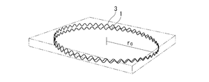
第一冠ギヤ1及び第三冠ギヤ3の歯形曲面の設計は、図9に示すように、まず、第一冠ギヤ1及び第三冠ギヤ3の基準円rc上の歯形曲線を作成することから始まる。作成した歯形曲線は一本の曲線であり、面ではない。第一冠ギヤ1及び第三冠ギヤ3の歯形曲面を得るために、基準円の半径rcを変化させて得られる歯形曲線を第一冠ギヤ1及び第三冠ギヤ3の円錐形の母体に沿って並べる。これにより、第一冠ギヤ1及び第三冠ギヤ3の歯形曲面が得られる。
(歯形曲線の設計指針)
(歯形曲線の設計指針)
第一冠ギヤ1及び第三冠ギヤ3の歯先部1a2,3a2が円錐の側面から構成されるとし、基準円rc上の第一冠ギヤ1及び第三冠ギヤ3の歯先部1a2,3a2の曲線を単一Rの円弧とする。このとき、歯先部1a2,3a2と歯底部1a1,3a1が互いに転がり運動を行うためには、歯底部1a1,3a1の歯底曲線は、歯先部1a2,3a2が描く軌跡となる。歯先部1a2,3a2の単一Rの円弧と歯底部1a1,3a1の歯底曲線を滑らかに接続することで、図9に示すように、第一冠ギヤ1及び第三冠ギヤ3の基準円rc上の歯形曲線が得られる。歯形曲線の作成は、下記の順序で行われる。
(i)波動運動(以下、歳差運動という)によって歯先部1a2,3a2が通るべき曲線(トロコイド曲線)を求める。
(ii)歯先部1a2,3a2の半径を仮定し、歯先部1a2,3a2が(i)で求めたトロコイド曲線上を通ったときに描く曲線を求め、これを歯底部1a1,3a1の歯底曲線とする。
(iii)歯先部1a2,3a2の歯先曲線(円弧)と歯底部1a1,3a1の歯底曲線とを互いになめらかに接続するように歯先部1a2,3a2の半径を決定する。
(歯先部が通るべきトロコイド曲線の計算)
(ii)歯先部1a2,3a2の半径を仮定し、歯先部1a2,3a2が(i)で求めたトロコイド曲線上を通ったときに描く曲線を求め、これを歯底部1a1,3a1の歯底曲線とする。
(iii)歯先部1a2,3a2の歯先曲線(円弧)と歯底部1a1,3a1の歯底曲線とを互いになめらかに接続するように歯先部1a2,3a2の半径を決定する。
(歯先部が通るべきトロコイド曲線の計算)
第三冠ギヤ3は、歳差運動をしながら第一冠ギヤ1に噛み合う。第一冠ギヤ1は、第三冠ギヤ3に向かって凸の円錐形の母体を持ち、第三冠ギヤ3は、第一冠ギヤ1に向かってすり鉢状の円錐形の母体を持つ。第一冠ギヤ1及び第三冠ギヤ3それぞれの歯面はそれぞれの円錐形の母体上にある。したがって、周方向には合同な歯形曲線が並ぶが、半径方向では歯形曲線は相似ではあるが合同ではない。このため、ある基準円rcを定め、この基準円rc上での歯形曲線を求める。
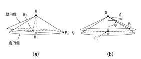
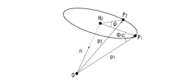
まず、この基準円rcを底面にもつ2つの円錐があり、図10(a)に示すように互いの頂点と母線が接触している状態を仮定し、歳差運動を行う円錐を動円錐、固定された円錐を定円錐とする。ここで、円錐頂点を原点O、底面同士の接触点を点P1、動円錐の底面上の定点を点P2、定円錐の頂点から底面へ下ろした垂線の足をH1、動円錐の頂点から底面へ下ろした垂線の足をH2とする。このとき、動円錐を歳差運動させたときの点P2の描く軌跡が歯の通るべき曲線(トロコイド曲線)となる。いま、図10(b)に示すように、動円錐が定円錐から離れることなく歳差運動を行った場合を考える。この歳差運動が、動円錐が自身の軸OH2回りに-ψだけ回転し、かつ定円錐回りをθ回転するものだとすれば、点P1がOH1回りにθ、点P2がOH2回りに-ψ回転したものとみなせる。ここで、図11に示すように、線分OH2に平行で正規化したベクトルをn、点Oから点P1までのベクトルをp1、点Oから点P2までのベクトルをp2とすれば、p2はp1をn回りにψだけ回転したベクトルとみなせるため、

と表すことができる。ここで、動円錐の底面半径をrcr、底角をΦcrとし、定円錐の底面半径をrcf、底角をΦcfとすれば、nとp1はそれぞれ、

と表すことができる。
ここまで求めてきたp2は、ψの値を変えることで第一冠ギヤ1と第三冠ギヤ3それぞれの歯先部1a2,3a2の中心が通るべき曲線を表すベクトルを表すことができる。まず、第三冠ギヤ3の歯先部3a2の中心が通るべき曲線を求める。動円錐が第三冠ギヤ3、定円錐が第一冠ギヤ1とみなし、歯数をそれぞれzi,z0とする。また、動円錐の歳差運動のパラメータはθ=θi,ψ=ψiとする。このとき、正転ギヤであれば、図12に示すようにθが1回転する間にψは反対方向に1歯分だけ多く回転し、逆転ギヤであれば、θが1回転する間にψは反対方向に1歯分だけ少なく回転するため、数4が成り立つ。

これを整理して、

第一冠ギヤ1の歯先部1a2の中心が通るべき曲線を求める場合、動円錐を第一冠ギヤ1、定円錐を第三冠ギヤ3とみなし、歳差運動のパラメータはθ=θo,ψ=ψoとすれば、同様にして数6が成り立つ。

このように、組み合わせるギヤの特性によって、数5、数6を選択し、ψについて数2に代入することで、歯先部の中心が通るべき曲線を求められる。このとき、求めた曲線の例を図13に示す。図13において、ベクトルp2が描く軌跡がトロコイド曲線である。p1とp2の回転角と方向は図12と同じである。
(歯底曲線の計算)
(歯底曲線の計算)
次に、歯底曲線を求める。図14に示すように相手側ギヤの歯先部3a2が描く軌跡が歯底曲線p3となる。すなわち、相手側ギヤの歯先部3a2の中心が通るべきトロコイド曲線p2を求め、相手側ギヤの歯先部3a2の半径をもつ円をこのトロコイド曲線p2上で動かしたときに得られる軌跡を計算すればよい。ここで、相手側ギヤの歯先半径をhk、この円をCとする。このとき、図15に示すように、歯底曲線を表すベクトルp3は、p2上に円Cを描いたときの点のうち、p2とp2の方向ベクトルΔp2のどちらにも直交する点P3までのベクトルとなる。したがって、数7と数8の関係が成り立つ。


以上の結果から、

が成り立つ。なお、式中の正負は、方向ベクトルの向きによって決定される。
(歯先曲線と歯底曲線の接続)
図16(a)は、上記に従って計算した第三冠ギヤ3の歯形曲線(歯先曲線と歯底曲線)を示し、図16(b)は、上記に従って計算した第一冠ギヤ1の歯形曲線(歯先曲線と歯底曲線)を示す。ここでは、歯先曲線と歯底曲線が滑らかに繋がるように歯先曲線の半径を決定する。歯先曲線の半径は、「歯先曲線と歯底曲線が接点をただ一つ持つとき」を条件にして決定する。(歯先曲線の方程式)=(歯底曲線の方程式)を立式し、これが重解を持つときの歯先半径の値を探せばよい。以上により、第一冠ギヤ1及び第三冠ギヤ3の歯形曲線を生成することができる。
図17は、上記に従って得られた第一冠ギヤ1及び第三冠ギヤ3の歯形曲線を示す。図中の黒丸が接触点を示す。(S1)の接触開始時から(S5)の接触終了時に至るまで、第一冠ギヤ1と第三冠ギヤ3とが常に接触し、接触点が移動することがわかる。接触点が移動することから、第一冠ギヤ1と第三冠ギヤ3とが互いに転がることがわかる。この図17には第一冠ギヤ1が円周方向に移動するように示されているが、実際には第三冠ギヤ3が円周方向に移動する。
なお、第一冠ギヤ1及び第三冠ギヤ3の歯底部1a1,3a1を円錐の側面から構成し、第一冠ギヤ1及び第三冠ギヤ3の歯先部1a2,3a2をトロコイド曲線を用いて生成することもできる。この場合、基準円rc上の第一冠ギヤ1及び第三冠ギヤ3の歯底部1a1,3a1の曲線を単一Rの円弧とし、トロコイド曲線を用いて歯先部1a2,3a2の歯先曲線を計算すればよい。
<第一ないし第三冠ギヤの歯の形状のさらに他の例(歯すじがヘリカル状である例)>
<第一ないし第三冠ギヤの歯の形状のさらに他の例(歯すじがヘリカル状である例)>
図18に示すように、第三冠ギヤ3の基準円上の歯形曲線の位相を、基準円の半径を変化させる毎に円周方向にずらすことで、歯先部3a2及び歯底部3a1の歯すじをヘリカル状にすることができる。図18に示すように、第三冠ギヤ3の外側と内側とでは、歯形曲線の位相が異なる。同様に、第一冠ギヤ1の歯すじも同様にヘリカル状にすることができる。
ヘリカル状の歯すじには、図19に示す対数らせんを採用することができる。対数らせんは、円錐形の母体の母線とのなす角βが常に一定のらせんであり、数10で表すことができる。

ここで、a,bはらせんの巻き方のパラメータである。
<本実施形態の減速装置の効果>
以上に本実施形態の減速装置の構造を説明した。本実施形態の減速装置によれば、以下の効果を奏する。
波動運動する第三冠ギヤ3を第一カム11と第二カム12とで挟むので、第三冠ギヤ3を高い剛性で支持することができる。また、第一及び第二カム11,12と第三冠ギヤ3との間に第一及び第二ボール15,17が介在するので、第三冠ギヤ3を円滑に回転させることができ、減速装置の効率を向上させることができる。
第一及び第二カム11,12、並びに第三冠ギヤ3を貫通する真直な入力軸5に第一及び第二カム11,12を固定するので、第一及び第二カム11,12で第三冠ギヤ3を挟む構造、及びこれらの組立て性が向上する。
第一及び第二カム11,12に第一及び第二ボール転走溝11a1,12a1を形成し、第三冠ギヤ3に第三及び第四ボール転走溝3c1,3c2を形成するので、第一及び第二ボール15,17が負荷できる荷重を増やすことができ、第三冠ギヤ3の支持剛性がより向上する。
第一カム11の第一ボール転走溝11a1の中心C1と第二カム12の第二ボール転走溝12a1の中心C2とを入力軸5の軸線5aからずらすことで、厚みのある第三冠ギヤ3の波動運動の中心Pを入力軸5の軸線5a上に配置することができる。
第一冠ギヤ1の歯先部1a2、第二冠ギヤ2の歯先部2a2、第三冠ギヤ3の歯先部3a2,3b2が円錐Co1´~Co4´(Co1´、Co3´のみを図示する)の側面を基礎とした凸形状であり、第一冠ギヤ1の歯底部1a1、第二冠ギヤ2の歯底部2a1、第三冠ギヤ3の歯底部3a1,3b1が円錐Co1~Co4の側面を基礎とした凹形状であるので、これらの噛み合いのほとんどを転がりにすることができ、歯車の効率を向上させることができる。
なお、本発明において、「円錐の側面を基礎とした凸形状及び凹形状」は、円錐Co1~Co4,Co1´~Co4´の側面から構成される凸形状及び凹形状、並びに第三冠ギヤ3の円錐形の母体を第一冠ギヤ1又は第二冠ギヤ2の円錐形の母体に沿って転がしたときに描かれるトロコイド曲線を用いて生成された凸形状及び凹形状を含む。また、このような凸形状及び凹形状を持つ歯先部1a2,2a2,3a2,3b2及び歯底部1a1,2a1,3a1,3b1の歯すじがヘリカル状である場合を含む。
円錐Co1~Co4,Co1´~Co4´の頂点Pが第三冠ギヤ3の歳差運動の中心Pに一致するので、歯先部1a2,2a2,3a2,3b2と歯底部1a1,2a1,3a1,3b1とを線接触させることができる。歯当たり面積を大きく、噛み合い率を大きくすることができるので、高剛性化、高効率、静音化が実現できる。
なお、本発明は、上記実施形態に具現化されるのに限られることはなく、本発明の要旨を変更しない範囲でさまざまな実施形態に具現化可能である。上記実施形態では、第一及び第二カムと第三冠ギヤとの間に第一及び第二ボールを介在させているが、第一及び第二ローラを介在させることもできる。
本発明の減速又は増速装置の用途は、特に限定されるものではなく、ロボットの関節、工作機械、自動車等のさまざまな用途に使用することができる。減速比を大きくすることができ、バックラッシもないことから、高精度の位置決めに適しており、半導体又は液晶製造装置、電子顕微鏡等にも使用することができる。また、入力側と出力側を逆にすることで、増速装置として使用することもでき、水力発電機のような入力側のパワーの大きい発電機の増速装置として使用することができる。
本明細書は、2015年5月25日出願の特願2015-105072及び2016年3月2日出願の特願2016-039521に基づく。この内容はすべてここに含めておく。
1…第一冠ギヤ、1a…第一冠ギヤの対向歯、1a1…第一冠ギヤの対向歯の歯底部、1a2…第一冠ギヤの対向歯の歯先部、2…第二冠ギヤ、2a…第二冠ギヤの対向歯、2a1…第二冠ギヤの対向歯の歯底部、2a2…第二冠ギヤの対向歯の歯先部、3…第三冠ギヤ、3a…第三冠ギヤの対向歯、3a1…第三冠ギヤの対向歯の歯底部、3a2…第三冠ギヤの対向歯の歯先部、3b…第三冠ギヤの対向歯、3b1…第三冠ギヤの対向歯の歯底部、3b2…第三冠ギヤの対向歯の歯先部、3c1…第三ボール転走溝(第三転動体転走溝)、3c2…第四ボール転走溝(第四転動体転走溝)、5…入力軸(軸)、5a…軸線、7…出力部、11…第一カム(カム部)、11a…第一傾斜面、11a1…第一ボール転走溝(第一転動体転走溝)、12…第二カム(カム部)、12a…第二傾斜面、12a1…第二ボール転走溝(第二転動体転走溝)、15…第一ボール(第一転動体)、17…第二ボール(第二転動体)、C1…第一ボール転走溝の中心(第一転動体転走溝の中心)、C2…第二ボール転走溝の中心(第二転動体転走溝の中心)、P…第一ないし第三冠ギヤの噛み合い中心(第三冠ギヤの波動運動の中心)、Co1~Co4,Co1´,Co3´…円錐
Claims (6)
- 第一冠ギヤと、
第二冠ギヤと、
前記第一冠ギヤに対向する対向歯と前記第二冠ギヤに対向する対向歯とを背面合わせで持つ第三冠ギヤと、
前記第三冠ギヤが前記第一冠ギヤに噛み合い、前記第三冠ギヤが前記第二冠ギヤに噛み合うように、前記第三冠ギヤを前記第一冠ギヤ及び前記第二冠ギヤに対して傾斜させ、かつ噛み合う箇所が円周方向に移動するように前記第三冠ギヤを波動運動させるカム部と、を備え、
前記カム部は、前記第三冠ギヤよりも前記第一冠ギヤ側に配置される第一カムと、前記第三冠ギヤよりも前記第二冠ギヤ側に配置される第二カムと、を有し、
前記第一カムと前記第二カムとで前記第三冠ギヤを挟み、
前記第一カムと前記第三冠ギヤとの間に転がり運動可能に第一転動体が介在し、
前記第二カムと前記第三冠ギヤとの間に転がり運動可能に第二転動体が介在する減速又は増速装置。 - 前記第一及び前記第二カムは、前記第一及び前記第二カム並びに前記第三冠ギヤを貫通する真直な軸に固定されることを特徴とする請求項1に記載の減速又は増速装置。
- 前記第一及び前記第二カムは、互いに平行で、前記第一及び前記第二カムの軸線に対して傾斜する第一及び第二傾斜面を有し、
前記第一及び前記第二傾斜面に、前記第一及び前記第二傾斜面に対して直交する方向から見て円形の第一及び第二転動体転走溝が形成され、
前記第三冠ギヤに、前記第一及び前記第二転動体転走溝に対向する円形の第三及び第四転動体転走溝が背面合わせで形成されることを特徴とする請求項1又は2に記載の減速又は増速装置。 - 厚みのある前記第三冠ギヤの波動運動の中心が前記第一及び前記第二カムの軸線上にあるように、前記第一カムの前記第一転動体転走溝の中心と前記第二カムの前記第二転動体転走溝の中心とが前記軸線からずれることを特徴とする請求項3に記載の減速又は増速装置。
- 前記第一冠ギヤ、前記第二冠ギヤ及び前記第三冠ギヤの対向歯は、歯先部と歯底部とを円周方向に交互に有し、
前記歯先部が、円錐の側面を基礎とした凸形状であり、
前記歯底部が、円錐の側面を基礎とした凹形状であることを特徴とする請求項1ないし4のいずれか1項に記載の減速又は増速装置。 - 前記円錐の頂点が前記第三冠ギヤの波動運動の中心に一致することを特徴とする請求項5に記載の減速又は増速装置。
Priority Applications (3)
| Application Number | Priority Date | Filing Date | Title |
|---|---|---|---|
| CN201680030287.XA CN107614931B (zh) | 2015-05-25 | 2016-04-12 | 减速或增速装置 |
| DE112016002380.4T DE112016002380T5 (de) | 2015-05-25 | 2016-04-12 | Drehzahlreduktions- oder Drehzahlerhöhungsvorrichtung |
| US15/569,128 US10281008B2 (en) | 2015-05-25 | 2016-04-12 | Speed reduction or speed increasing apparatus |
Applications Claiming Priority (4)
| Application Number | Priority Date | Filing Date | Title |
|---|---|---|---|
| JP2015-105072 | 2015-05-25 | ||
| JP2015105072 | 2015-05-25 | ||
| JP2016-039521 | 2016-03-02 | ||
| JP2016039521A JP6010243B1 (ja) | 2015-05-25 | 2016-03-02 | 減速又は増速装置 |
Publications (1)
| Publication Number | Publication Date |
|---|---|
| WO2016189989A1 true WO2016189989A1 (ja) | 2016-12-01 |
Family
ID=57140243
Family Applications (1)
| Application Number | Title | Priority Date | Filing Date |
|---|---|---|---|
| PCT/JP2016/061766 Ceased WO2016189989A1 (ja) | 2015-05-25 | 2016-04-12 | 減速又は増速装置 |
Country Status (6)
| Country | Link |
|---|---|
| US (1) | US10281008B2 (ja) |
| JP (1) | JP6010243B1 (ja) |
| CN (1) | CN107614931B (ja) |
| DE (1) | DE112016002380T5 (ja) |
| TW (1) | TWI614431B (ja) |
| WO (1) | WO2016189989A1 (ja) |
Cited By (1)
| Publication number | Priority date | Publication date | Assignee | Title |
|---|---|---|---|---|
| WO2020049938A1 (ja) * | 2018-09-06 | 2020-03-12 | Thk株式会社 | アクチュエータ |
Families Citing this family (14)
| Publication number | Priority date | Publication date | Assignee | Title |
|---|---|---|---|---|
| US10267383B2 (en) * | 2017-05-03 | 2019-04-23 | The Boeing Company | Self-aligning virtual elliptical drive |
| US10392094B2 (en) * | 2017-06-06 | 2019-08-27 | The Boeing Company | Transmissions for rotating coaxial drive shafts in opposite directions |
| KR102189843B1 (ko) | 2018-09-14 | 2020-12-11 | 류근웅 | 병렬형 블록체인 기반 정보 관리 및 운영 시스템 |
| KR102406241B1 (ko) | 2018-09-14 | 2022-06-08 | 류근웅 | 반중앙화 방식의 블록체인 기반 정보 관리 및 운영 시스템 |
| AT521780B1 (de) * | 2019-01-03 | 2020-07-15 | Miba Sinter Austria Gmbh | Verfahren zur Einstellung eines Zahnflankenspiels |
| KR102752750B1 (ko) * | 2019-02-19 | 2025-01-10 | 엘지이노텍 주식회사 | 필터 액추에이터 및 이를 포함하는 카메라 모듈 |
| MD4781C1 (ro) * | 2019-12-31 | 2022-07-31 | Виорел БОСТАН | Transmisii planetare precesionale |
| DE102020103026A1 (de) | 2020-02-06 | 2021-08-12 | Rolless Gmbh | Getriebe und Hilfsantrieb für ein Fahrzeug |
| CN111219447B (zh) * | 2020-03-17 | 2022-07-19 | 苏州大学 | 一种弧面二次包络冠齿轮章动传动装置 |
| CN111237400B (zh) * | 2020-03-20 | 2023-01-17 | 苏州大学 | 双球面摆线滚子章动传动装置 |
| CN114198460B (zh) * | 2021-12-22 | 2023-05-16 | 姜虹 | 一种章动减速器 |
| CN114198464B (zh) * | 2021-12-22 | 2023-04-28 | 姜虹 | 一种齿轮副及章动减速器 |
| KR102605516B1 (ko) * | 2022-02-14 | 2023-11-23 | 블루로빈 주식회사 | 조화 감속기 및 이를 포함하는 동력 전달 시스템 |
| DE102024102315B4 (de) * | 2024-01-26 | 2025-11-13 | Harald Weisz | Exzentergetriebe mit rotationssymmetrischen Übertragungselementen |
Citations (3)
| Publication number | Priority date | Publication date | Assignee | Title |
|---|---|---|---|---|
| JPS5939346U (ja) * | 1982-09-07 | 1984-03-13 | 有限会社大機製作所 | 高減速比を有する向斜面「ばい」歯車装置 |
| JPH01229165A (ja) * | 1988-03-10 | 1989-09-12 | Shinko Seisakusho:Kk | フェースギャの歯形、該歯形の創成加工方法及び該歯形を利用した差動減速装置 |
| JPH06235445A (ja) * | 1993-02-09 | 1994-08-23 | Hiroshi Murakami | 減速装置 |
Family Cites Families (10)
| Publication number | Priority date | Publication date | Assignee | Title |
|---|---|---|---|---|
| US544796A (en) * | 1895-08-20 | Gearing | ||
| DE838100C (de) * | 1952-03-27 | Staad Rorschach Alois Tscherne (Schweiz) | Reduziergetriebe mit Selbsthemmung | |
| US1611981A (en) * | 1922-03-23 | 1926-12-28 | William O Peterson | Gear mechanism |
| US2699690A (en) * | 1951-03-06 | 1955-01-18 | Arnold J Kobler | Speed reduction gearing |
| DE3033521A1 (de) | 1980-09-05 | 1982-04-29 | Robert Hadlow South Canterbury Davidson | Mechanische kraftuebertragung |
| JPS5939346A (ja) | 1982-08-27 | 1984-03-03 | Kiyataraa Kogyo Kk | セラミツクハニカム触媒担体の製造方法 |
| JPS604647A (ja) | 1983-06-22 | 1985-01-11 | Sanwa Tekki Corp | フエ−スギア減速機の軸受装置 |
| SU1545019A1 (ru) | 1987-07-20 | 1990-02-23 | Ленинградский Политехнический Институт Им.М.И.Калинина | Планетарна коническа зубчата передача |
| CN2235046Y (zh) | 1995-06-23 | 1996-09-11 | 韩利生 | 齿轮减速器 |
| WO2014076771A1 (ja) * | 2012-11-13 | 2014-05-22 | 国立大学法人福島大学 | クラウンギア減速機構 |
-
2016
- 2016-03-02 JP JP2016039521A patent/JP6010243B1/ja active Active
- 2016-04-12 DE DE112016002380.4T patent/DE112016002380T5/de active Pending
- 2016-04-12 US US15/569,128 patent/US10281008B2/en active Active
- 2016-04-12 CN CN201680030287.XA patent/CN107614931B/zh active Active
- 2016-04-12 WO PCT/JP2016/061766 patent/WO2016189989A1/ja not_active Ceased
- 2016-04-19 TW TW105112107A patent/TWI614431B/zh active
Patent Citations (3)
| Publication number | Priority date | Publication date | Assignee | Title |
|---|---|---|---|---|
| JPS5939346U (ja) * | 1982-09-07 | 1984-03-13 | 有限会社大機製作所 | 高減速比を有する向斜面「ばい」歯車装置 |
| JPH01229165A (ja) * | 1988-03-10 | 1989-09-12 | Shinko Seisakusho:Kk | フェースギャの歯形、該歯形の創成加工方法及び該歯形を利用した差動減速装置 |
| JPH06235445A (ja) * | 1993-02-09 | 1994-08-23 | Hiroshi Murakami | 減速装置 |
Cited By (1)
| Publication number | Priority date | Publication date | Assignee | Title |
|---|---|---|---|---|
| WO2020049938A1 (ja) * | 2018-09-06 | 2020-03-12 | Thk株式会社 | アクチュエータ |
Also Published As
| Publication number | Publication date |
|---|---|
| DE112016002380T5 (de) | 2018-02-15 |
| US20180106328A1 (en) | 2018-04-19 |
| JP6010243B1 (ja) | 2016-10-19 |
| TW201704660A (zh) | 2017-02-01 |
| TWI614431B (zh) | 2018-02-11 |
| CN107614931B (zh) | 2019-08-20 |
| US10281008B2 (en) | 2019-05-07 |
| CN107614931A (zh) | 2018-01-19 |
| JP2016217532A (ja) | 2016-12-22 |
Similar Documents
| Publication | Publication Date | Title |
|---|---|---|
| JP6010243B1 (ja) | 減速又は増速装置 | |
| JP5335152B1 (ja) | 波動歯車装置の波動発生器 | |
| CN110469651A (zh) | 波动齿轮装置 | |
| US10161480B2 (en) | Eccentric oscillating speed reducer | |
| JP2019148308A (ja) | 偏心揺動型減速装置 | |
| JP2017137989A (ja) | 減速機 | |
| CN107250607B (zh) | 减速或者增速装置 | |
| JP2024061877A (ja) | 偏心揺動型歯車装置 | |
| TWI763689B (zh) | 齒輪裝置 | |
| JP6770873B2 (ja) | 減速又は増速装置及びアクチュエータ | |
| JP5475153B2 (ja) | 撓み噛合い式歯車装置 | |
| JP6803273B2 (ja) | 差動減速機 | |
| JP6690964B2 (ja) | 減速又は増速装置 | |
| JP2014139483A (ja) | 減速装置 | |
| JP6777404B2 (ja) | 減速又は増速装置 | |
| JP2017125597A (ja) | 歯車伝達装置 | |
| US12366283B2 (en) | Speed reducer | |
| JP2015121239A (ja) | 偏心揺動型減速機 | |
| JP7614753B2 (ja) | 減速又は増速装置 | |
| JP2016211643A (ja) | 減速装置および減速装置の製造方法 | |
| JP7770417B2 (ja) | はすば歯車及び減速機 | |
| WO2022210339A1 (ja) | ころ軸受け及び遊星減速機 | |
| JP2022163521A (ja) | 減速機 | |
| CN111043252A (zh) | 减速机的齿间传动结构 | |
| JP2018076887A (ja) | 波動歯車装置 |
Legal Events
| Date | Code | Title | Description |
|---|---|---|---|
| 121 | Ep: the epo has been informed by wipo that ep was designated in this application |
Ref document number: 16799697 Country of ref document: EP Kind code of ref document: A1 |
|
| WWE | Wipo information: entry into national phase |
Ref document number: 15569128 Country of ref document: US |
|
| WWE | Wipo information: entry into national phase |
Ref document number: 112016002380 Country of ref document: DE |
|
| 122 | Ep: pct application non-entry in european phase |
Ref document number: 16799697 Country of ref document: EP Kind code of ref document: A1 |