WO2016189823A1 - カメラカバー及びそれを備えた撮像システム - Google Patents
カメラカバー及びそれを備えた撮像システム Download PDFInfo
- Publication number
- WO2016189823A1 WO2016189823A1 PCT/JP2016/002384 JP2016002384W WO2016189823A1 WO 2016189823 A1 WO2016189823 A1 WO 2016189823A1 JP 2016002384 W JP2016002384 W JP 2016002384W WO 2016189823 A1 WO2016189823 A1 WO 2016189823A1
- Authority
- WO
- WIPO (PCT)
- Prior art keywords
- air
- lid
- camera
- camera cover
- housing
- Prior art date
- Legal status (The legal status is an assumption and is not a legal conclusion. Google has not performed a legal analysis and makes no representation as to the accuracy of the status listed.)
- Ceased
Links
Images





Classifications
-
- G—PHYSICS
- G03—PHOTOGRAPHY; CINEMATOGRAPHY; ANALOGOUS TECHNIQUES USING WAVES OTHER THAN OPTICAL WAVES; ELECTROGRAPHY; HOLOGRAPHY
- G03B—APPARATUS OR ARRANGEMENTS FOR TAKING PHOTOGRAPHS OR FOR PROJECTING OR VIEWING THEM; APPARATUS OR ARRANGEMENTS EMPLOYING ANALOGOUS TECHNIQUES USING WAVES OTHER THAN OPTICAL WAVES; ACCESSORIES THEREFOR
- G03B17/00—Details of cameras or camera bodies; Accessories therefor
- G03B17/56—Accessories
-
- H—ELECTRICITY
- H04—ELECTRIC COMMUNICATION TECHNIQUE
- H04N—PICTORIAL COMMUNICATION, e.g. TELEVISION
- H04N23/00—Cameras or camera modules comprising electronic image sensors; Control thereof
- H04N23/80—Camera processing pipelines; Components thereof
- H04N23/81—Camera processing pipelines; Components thereof for suppressing or minimising disturbance in the image signal generation
- H04N23/811—Camera processing pipelines; Components thereof for suppressing or minimising disturbance in the image signal generation by dust removal, e.g. from surfaces of the image sensor or processing of the image signal output by the electronic image sensor
-
- B—PERFORMING OPERATIONS; TRANSPORTING
- B08—CLEANING
- B08B—CLEANING IN GENERAL; PREVENTION OF FOULING IN GENERAL
- B08B17/00—Methods preventing fouling
- B08B17/02—Preventing deposition of fouling or of dust
- B08B17/04—Preventing deposition of fouling or of dust by using removable coverings
-
- B—PERFORMING OPERATIONS; TRANSPORTING
- B08—CLEANING
- B08B—CLEANING IN GENERAL; PREVENTION OF FOULING IN GENERAL
- B08B5/00—Cleaning by methods involving the use of air flow or gas flow
- B08B5/02—Cleaning by the force of jets, e.g. blowing-out cavities
-
- B—PERFORMING OPERATIONS; TRANSPORTING
- B23—MACHINE TOOLS; METAL-WORKING NOT OTHERWISE PROVIDED FOR
- B23P—METAL-WORKING NOT OTHERWISE PROVIDED FOR; COMBINED OPERATIONS; UNIVERSAL MACHINE TOOLS
- B23P19/00—Machines for simply fitting together or separating metal parts or objects, or metal and non-metal parts, whether or not involving some deformation; Tools or devices therefor so far as not provided for in other classes
- B23P19/04—Machines for simply fitting together or separating metal parts or objects, or metal and non-metal parts, whether or not involving some deformation; Tools or devices therefor so far as not provided for in other classes for assembling or disassembling parts
-
- B—PERFORMING OPERATIONS; TRANSPORTING
- B25—HAND TOOLS; PORTABLE POWER-DRIVEN TOOLS; MANIPULATORS
- B25J—MANIPULATORS; CHAMBERS PROVIDED WITH MANIPULATION DEVICES
- B25J11/00—Manipulators not otherwise provided for
-
- B—PERFORMING OPERATIONS; TRANSPORTING
- B25—HAND TOOLS; PORTABLE POWER-DRIVEN TOOLS; MANIPULATORS
- B25J—MANIPULATORS; CHAMBERS PROVIDED WITH MANIPULATION DEVICES
- B25J19/00—Accessories fitted to manipulators, e.g. for monitoring, for viewing; Safety devices combined with or specially adapted for use in connection with manipulators
- B25J19/02—Sensing devices
- B25J19/04—Viewing devices
-
- G—PHYSICS
- G03—PHOTOGRAPHY; CINEMATOGRAPHY; ANALOGOUS TECHNIQUES USING WAVES OTHER THAN OPTICAL WAVES; ELECTROGRAPHY; HOLOGRAPHY
- G03B—APPARATUS OR ARRANGEMENTS FOR TAKING PHOTOGRAPHS OR FOR PROJECTING OR VIEWING THEM; APPARATUS OR ARRANGEMENTS EMPLOYING ANALOGOUS TECHNIQUES USING WAVES OTHER THAN OPTICAL WAVES; ACCESSORIES THEREFOR
- G03B11/00—Filters or other obturators specially adapted for photographic purposes
- G03B11/04—Hoods or caps for eliminating unwanted light from lenses, viewfinders or focusing aids
- G03B11/043—Protective lens closures or lens caps built into cameras
-
- G—PHYSICS
- G03—PHOTOGRAPHY; CINEMATOGRAPHY; ANALOGOUS TECHNIQUES USING WAVES OTHER THAN OPTICAL WAVES; ELECTROGRAPHY; HOLOGRAPHY
- G03B—APPARATUS OR ARRANGEMENTS FOR TAKING PHOTOGRAPHS OR FOR PROJECTING OR VIEWING THEM; APPARATUS OR ARRANGEMENTS EMPLOYING ANALOGOUS TECHNIQUES USING WAVES OTHER THAN OPTICAL WAVES; ACCESSORIES THEREFOR
- G03B17/00—Details of cameras or camera bodies; Accessories therefor
- G03B17/02—Bodies
-
- H—ELECTRICITY
- H04—ELECTRIC COMMUNICATION TECHNIQUE
- H04N—PICTORIAL COMMUNICATION, e.g. TELEVISION
- H04N23/00—Cameras or camera modules comprising electronic image sensors; Control thereof
- H04N23/50—Constructional details
-
- H—ELECTRICITY
- H04—ELECTRIC COMMUNICATION TECHNIQUE
- H04N—PICTORIAL COMMUNICATION, e.g. TELEVISION
- H04N23/00—Cameras or camera modules comprising electronic image sensors; Control thereof
- H04N23/50—Constructional details
- H04N23/51—Housings
-
- H—ELECTRICITY
- H04—ELECTRIC COMMUNICATION TECHNIQUE
- H04N—PICTORIAL COMMUNICATION, e.g. TELEVISION
- H04N23/00—Cameras or camera modules comprising electronic image sensors; Control thereof
- H04N23/50—Constructional details
- H04N23/55—Optical parts specially adapted for electronic image sensors; Mounting thereof
-
- Y—GENERAL TAGGING OF NEW TECHNOLOGICAL DEVELOPMENTS; GENERAL TAGGING OF CROSS-SECTIONAL TECHNOLOGIES SPANNING OVER SEVERAL SECTIONS OF THE IPC; TECHNICAL SUBJECTS COVERED BY FORMER USPC CROSS-REFERENCE ART COLLECTIONS [XRACs] AND DIGESTS
- Y10—TECHNICAL SUBJECTS COVERED BY FORMER USPC
- Y10S—TECHNICAL SUBJECTS COVERED BY FORMER USPC CROSS-REFERENCE ART COLLECTIONS [XRACs] AND DIGESTS
- Y10S901/00—Robots
- Y10S901/14—Arm movement, spatial
- Y10S901/15—Jointed arm
-
- Y—GENERAL TAGGING OF NEW TECHNOLOGICAL DEVELOPMENTS; GENERAL TAGGING OF CROSS-SECTIONAL TECHNOLOGIES SPANNING OVER SEVERAL SECTIONS OF THE IPC; TECHNICAL SUBJECTS COVERED BY FORMER USPC CROSS-REFERENCE ART COLLECTIONS [XRACs] AND DIGESTS
- Y10—TECHNICAL SUBJECTS COVERED BY FORMER USPC
- Y10S—TECHNICAL SUBJECTS COVERED BY FORMER USPC CROSS-REFERENCE ART COLLECTIONS [XRACs] AND DIGESTS
- Y10S901/00—Robots
- Y10S901/30—End effector
- Y10S901/31—Gripping jaw
Definitions
- the present invention relates to a camera cover and an imaging system including the same.
- a manufacturing site for manufacturing a product is equipped with a camera for imaging component parts, products, and the like (hereinafter referred to as “workpieces”), and based on image information acquired by the camera, It is known to perform assembly and product inspection.
- workpieces for imaging component parts, products, and the like
- Patent Document 1 a work placed on a workbench is imaged with a camera installed above the workbench, and a predetermined work is performed on the work based on the position and orientation data of the work obtained from the image information. It is described to do.
- the camera installed at such a manufacturing site is usually installed so that the lens does not face upward, for example, downward or sideways, so that dust or dust does not fall and adhere to the lens of the camera.
- the present invention provides a camera cover that can prevent dust and dirt from being deposited on the camera lens even if the camera is arranged so that the camera lens faces upward, and an imaging system including the camera cover. With the goal.
- a camera cover for housing a camera lens, and includes a housing having an opening opened upward, and a lid attached to the housing. And a lid moving mechanism that moves the body between an open position that opens the opening and a closed position that closes the opening, and the lid is in the open position.
- “upward” includes not only vertically upward but also obliquely upward.
- the lid when the lid is in the closed position, the lid prevents the dust and the like from entering the housing through the opening, so the camera housed in the camera cover It is possible to prevent dust and dirt on the lens.
- the lid When the lid is in the open position, air is blown upward from the air blowing portion, that is, from the inside of the housing toward the opening of the housing. Thereby, even if the opening is opened, it is possible to prevent dust or dust from entering the housing and adhering to the camera lens by the air blown out from the air blowing portion.
- the lid is rotatably attached to the housing, and the lid moving mechanism is moved from one of an open position and a closed position by supplying air. It may be an air cylinder that moves the lid to the other position. According to this structure, the opening / closing operation
- movement of a cover body is realizable with a simple mechanism.
- the camera cover is provided in the air passage, branches from a control valve that controls the supply of air from the air supply source to the air blowing portion, and downstream of the control valve in the air passage,
- a branch path for introducing air to the lid body moving mechanism, and the lid body moving mechanism includes a branch path when the control valve is controlled to start supplying air to the air blowing section.
- the control valve is controlled to stop the supply of air to the air blowing section. It may be an air cylinder that stops supplying air and moves the lid from the open position to the closed position.
- An imaging system includes the above-described camera cover and a camera lens accommodated in the camera cover, and images a workpiece positioned above the camera cover when the lid is in an open position.
- a camera unit includes the above-described camera cover and a camera lens accommodated in the camera cover, and images a workpiece positioned above the camera cover when the lid is in an open position.
- the above imaging system may further include an articulated robot that holds the workpiece.
- the workpiece can be imaged while being held by the articulated robot, and since the camera cover is positioned below the workpiece, the articulated robot avoids the camera cover during work. There is no need to do. For this reason, the working time by the articulated robot can be shortened.
- the camera cover may be disposed outside the operating range of the articulated robot. According to this configuration, it is possible to reliably prevent the articulated robot from coming into contact with the camera cover.
- a camera cover that can prevent dust and dirt from being deposited on the camera lens even when the camera lens is arranged so that the camera lens faces upward, and an imaging system including the camera cover. Can do.
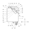
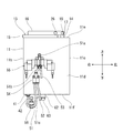
- FIG. 2 is a partial front view of the camera cover shown in FIG. 1, showing a state where the cover of the camera cover is in a closed position. It is a partial right view of the camera cover shown in FIG. It is a partial top view of the camera cover shown in FIG. It is a partial rear view of the camera cover shown in FIG. It is a figure which shows the state which has the cover body of the camera cover shown in FIG. 1 in an open position. It is a partial schematic sectional drawing of the camera cover shown in FIG. It is an air circuit diagram which shows the flow of the air of the camera cover shown in FIG.
- FIG. 1 is a schematic configuration diagram of an imaging system 1 including a camera cover 10 according to this embodiment.
- the imaging system 1 is incorporated in a manufacturing line for manufacturing products, and in this manufacturing line, parts are assembled using an industrial articulated robot 7.
- the imaging system 1 includes an articulated robot 7 that grips a work W, a camera unit 6 that captures an image of the work W gripped by the articulated robot 7, and a camera cover 10 that houses a camera lens 61 of the camera unit 6.
- the articulated robot 7 includes a base 71 fixed to a floor, a frame, or the like, a plurality of arms 72a to 72d, and a gripping portion 73 that grips a workpiece W.
- the plurality of arms 72a to 72d are connected in a row so as to be rotatable with respect to adjacent arms.
- the arm 72a at one end is rotatably connected to the base 71
- the grip portion 73 is rotatably connected to the arm 72d at the other end.
- the articulated robot 7 operates to grip the work W that is a work target by the gripping portion 73 and to transport the work W to a main body part (not shown), and assembles the work W on the main body part.
- the imaging system 1 images the workpiece W by the camera unit 6 and detects the phase of the workpiece W from the obtained image information. Then, based on the detected phase, the articulated robot 7 adjusts the phase of the gripped work W to the phase of the main body part, and then assembles the work W on the main body part.
- the camera unit 6 captures an image of the workpiece W gripped by the articulated robot 7 and conveyed above the camera unit 6 from below.
- the camera unit 6 has a camera lens 61 arranged so as to face upward.
- the camera lens 61 is accommodated in the camera cover 10 so that dust, dust, and the like fall and do not adhere to the camera lens.
- the camera cover 10 is disposed outside the operating range of the articulated robot 7 in order to reliably prevent the articulated robot 7 from coming into contact with the camera cover 10.
- FIGS. 2 to 5 are a partial front view, a partial right side view, a partial top view, and a partial rear view of the camera cover 10, respectively.
- 2 shows a state where the lid 13 of the camera cover 10 is in a closed position where the opening 12 is closed
- FIG. 6 shows a state where the lid 13 is in an open position where the opening 12 is opened.
- FIG. 7 is a partial schematic cross-sectional view of the camera cover 10. In each figure, some or all of the first to third air passages 51 to 53 described later, components of the camera unit 6, signal lines extending from the control valve 55, and the like are omitted for simplification.
- the camera cover 10 includes a housing 11 having an opening 12 that opens upward, and a lid 13 attached to the housing 11.
- the housing 11 accommodates the camera lens 61 by a substantially rectangular front wall 11a, right side wall 11b, left side wall 11c, rear wall 11d, top wall 11e, and bottom wall 11f.
- An internal space is formed.
- a lid support portion 14 for supporting the lid 13 so as to be rotatable with respect to the housing 11 via a rotation shaft 19. It is erected.
- the opening 12 is formed in a substantially square shape by a part of the upper edge of the right wall 11b, the right edge of the top wall 11e, and the upper edge of each of the front wall 11a and the rear wall 11d. Has been.
- the lid 13 is configured to be movable between a closed position (see FIG. 2) and an open position (see FIG. 6).
- the lid body 13 includes a plate portion 15 that closes the opening 12, and two plate support portions 16 that are fixed to the upper surface of the plate portion 15.
- the plate portion 15 has substantially the same shape as the opening portion 12 in plan view when the lid 13 is in the closed position.
- Each plate support portion 16 has a quadrangular prism shape extending from the lid support portion 14 toward the opening 12 when the lid 13 is in the closed position.
- Each plate support portion 16 is formed with a first insertion hole 17 and a second insertion hole 18 in a direction perpendicular to the longitudinal direction, and the plate support portion 16 has a rotation shaft 19 passing through the first insertion hole 17. It is rotatably supported by the lid support part 14 via the.
- an air cylinder 2 is attached to the front wall 11 a of the housing 11 as a lid moving mechanism that moves the lid 13 between the open position and the closed position.
- the air cylinder 2 includes a cylinder portion 22 having a piston 21 inside, and a piston rod 23 provided with a piston 21 at one end and transmitting motion from the piston 21.
- the cylinder portion 22 has an internal space in which the piston 21 moves. The internal space is partitioned by the piston 21 into a rod chamber 24 on the piston rod 23 side and a head chamber 25 on the opposite side.
- the piston rod 23 is connected to the lid body 13 via a connecting shaft 26 that passes through the second insertion hole 18 of the plate support 16 at the tip opposite to the piston 21.
- the lid 13 connected thereto moves between the open position and the closed position.
- the rod chamber 24 and the head chamber 25 are provided with air through holes 27 and 28 for supplying and discharging air, respectively.
- the piston rod 23 moves the lid 13 from the open position to the closed position via the connecting shaft 26 when air is supplied to the rod chamber 24 from the air passage hole 27 (see FIG. 2).
- the piston rod 23 moves the lid 13 from the closed position to the open position via the connecting shaft 26 when air is supplied to the head chamber 25 from the air passage hole 28 (see FIG. 6).
- the internal configuration of the housing 11 of the camera cover 10 will be described. Inside the housing 11, the above-described camera lens 61, the illumination unit 3 that emits light toward the workpiece W when the workpiece W is imaged by the camera unit 6, and the upper side when the lid 13 is in the open position And an air blowing section 4 for blowing air toward.
- the camera lens 61 is arranged facing the opening 12 of the housing 11 so that an image can be taken through the opening 12 of the housing 11.
- the camera unit 6 includes a camera lens 61 arranged to face upward, a camera casing 62 that holds the camera lens 61, and an image sensor that detects light guided through the camera lens 61 and converts it into an electrical signal. (Not shown).
- the camera casing 62 is fixed to the bottom wall 11f so as to penetrate the bottom wall 11f of the housing 11. Image information obtained by the imaging device of the camera unit 6 is sent to a control device (not shown) via a signal line (not shown) extending from the connection port 63 of the camera casing 62. In this control device, the phase of the workpiece W is detected based on the sent information, and the detected phase information is used for the assembling work in the articulated robot 7.
- the camera unit 6 may have a plurality of camera lenses, but it is not necessary that all the lenses are accommodated in the camera cover 10.
- the camera lens of the present invention refers to a lens disposed closest to (uppermost) the opening 12 through which light first passes among the plurality of lenses of the camera unit 6.
- the illumination unit 3 is supported by an illumination support base 31 fixed to the bottom wall 11 f of the housing 11.
- the illumination unit 3 is disposed upward between the camera lens 61 and the opening 12 in the housing 11.
- the illumination unit 3 in this embodiment is ring illumination, and is arranged so that the center axis of the ring illumination and the optical axis of the camera lens 61 coincide.
- An attachment portion 41 for attaching to the bottom wall 11f is provided at one end of the air blowing portion 4 so as to penetrate the bottom wall 11f of the housing 11, and an air supply port 42 is formed in the attachment portion 41. ing.
- the air supply port 42 is disposed outside the housing 11. The air supplied to the air supply port 42 is blown out from an air outlet 43 formed at the other end of the air blowing portion 4.
- FIG. 8 is an air circuit diagram for explaining supply of air to the air blowing portion 4 of the camera cover 10.
- the camera cover 10 branches from a first air passage 51 (air passage of the present invention) 51 that guides air from an air supply source 50 arranged outside the housing 11 to the air blowing portion 4, and the first air passage 51.
- a second air passage (branch path of the present invention) 52 that guides air to the head chamber 25 of the air cylinder 2.
- a control valve 55 for controlling whether or not to supply air to the air blowing section 4 is provided on the upstream side (air supply source 50 side) portion of the first air passage 51 with respect to the branch point 54 with the second air passage 52.
- the control valve 55 is a two-position valve that moves between a first operating position (upper position in FIG. 8) and a second operating position (lower position in FIG. 8). is there.
- One output port of the two output ports of the control valve 55 is connected to the downstream (air cylinder 2 side) portion 51 b of the first air passage 51 from the control valve 55.
- the camera cover 10 includes a third air passage 53 that connects the other output port of the control valve 55 and the rod chamber 24 of the air cylinder 2.
- the air supplied from the air supply source 50 passes through the control valve 55 and is supplied to the air blowing unit 4 through the first air passage 51, and at the same time, Air is also supplied to the head chamber 25 of the air cylinder 2 through the second air passage 52.
- the piston rod 23 operates and the lid 13 moves from the closed position to the open position.
- the third air passage 53 connected to the rod chamber 24 of the air cylinder 2 is connected to the exhaust port of the control valve 55 and released to the atmosphere.
- the air supplied from the air supply source 50 passes through the control valve 55 and is supplied to the rod chamber 24 of the air cylinder 2 through the third air passage 53. Is done. As a result, the piston rod 23 operates and the lid 13 moves from the open position to the closed position. At this time, the downstream portion 51b of the first air passage 51 from the control valve 55 is connected to the exhaust port of the control valve 55 and is released to the atmosphere.
- control valve 55 when the control valve 55 is shifted from the second operating position to the first operating position, the movement of the lid 13 from the closed position to the open position and the blowing of air from the air blowing unit 4 are performed simultaneously.
- control valve 55 When the control valve 55 is shifted from the first operating position to the second operating position, the movement of the lid 13 from the open position to the closed position and the stop of the air blowing from the air blowing unit 4 are performed simultaneously.
- a flow rate adjusting valve 56 that adjusts the flow rate of the air blown from the air blowing portion 4 is provided at a portion 51c downstream of the branch point 54 in the first air passage 51.
- the second air passage 52 and the third air passage 53 are respectively provided with flow rate adjusting valves 57 and 58 for controlling the air flow rate in order to adjust the speed of the piston rod 23.
- the control valve 55 is attached to the rear wall 11d of the casing 11, and the first to third air passages 51 to 53 are constituted by tubes or the like.
- the tube corresponding to a part of the second air passage 52 extending from the branch joint constituting the branch point 54 is connected to the flow rate adjusting valve 57 connected to the air passage hole 28 (FIG. 5). 2).
- a tube corresponding to a part of the third air passage 53 extending from the control valve 55 is connected to a flow rate adjusting valve 58 connected to the air passage hole 27 (see FIG. 2).
- the articulated robot 7 grips the work W that is a work target by the gripping portion 73 and transports the work W to the upper side of the camera cover 10.
- the control valve 55 is controlled so as to shift from the second operating position to the first operating position. Thereby, air is supplied from the air supply source 50 to the air blowing part 4 and the head chamber 25 of the air cylinder 2 respectively.
- the air cylinder 2 operates to move the lid 13 from the closed position to the open position, and air is blown out from the air blowing portion 4. While the lid 13 is in the open position, air continues to be blown out from the air blowing portion 4.
- the illumination of the illumination unit 3 is switched on and the workpiece W is imaged by the camera unit 6.
- control valve 55 is controlled to shift from the first operating position to the second operating position. Thereby, the supply of air from the air supply source 50 to the air blowing part 4 and the head chamber 25 of the air cylinder 2 is stopped. In this way, the air cylinder 2 operates to move the lid 13 from the open position to the closed position, and air blowing from the air blowing portion 4 stops.
- the image information of the workpiece W imaged by the camera unit 6 is sent to the control device via a signal line extending from the connection port 63 of the camera casing 62, and the phase of the workpiece W is detected. Based on the detected phase information, the articulated robot 7 adjusts the phase of the gripped work W to the phase of the main body part, and then transports the work W and assembles it to the main body part.
- the lid body 13 when the lid body 13 is in the closed position, the lid body 13 may cause dust or dust to enter the housing 11 through the opening 12. Therefore, it is possible to prevent dust and dirt from being deposited on the camera lens 61 accommodated in the camera cover 10.
- the lid 13 When the lid 13 is in the open position, air is blown upward from the air blowing portion 4, that is, from the inside of the housing 11 toward the opening 12 of the housing 11. Thereby, even if the opening 12 is opened, it is possible to prevent dust or dust from entering the housing 11 and adhering to the camera lens 61 by the air blown from the air blowing portion 4.
- the lid body 13 is rotatably attached to the housing 11, and air is supplied from the air cylinder 2 to the other position from the open position and the closed position. Since the lid 13 is moved to the position, the opening / closing operation of the lid 13 can be realized with a simple mechanism.
- air is guided to the air cylinder 2 through the second air passage 52 branched from the control valve 55 in the first air passage 51 on the downstream side, and the control valve 55 is blown out from the air cylinder 2.
- the lid 13 is moved from the closed position to the open position, and the control valve 55 is controlled to stop supplying air to the air blowing unit 4.
- the lid 13 is moved from the open position to the closed position.
- the workpiece W can be imaged from below the workpiece W while being gripped by the articulated robot 7, and the camera cover 10 is positioned below the workpiece W.
- the type robot 7 does not need to avoid the camera cover 10 during work. For this reason, the working time by the articulated robot 7 can be shortened.
- the shape and configuration of the casing 11 and the lid 13 and the arrangement of the air cylinder 2 and the air blowing part 4 are merely shown as examples in the above embodiment, and the scope of the present invention is limited to these. It is not a thing.
- the housing 11 does not have to be hermetically sealed when the lid body 13 is in the closed position, and may be anything that covers the camera lens 61 so that dust or the like is not deposited.
- some or all of the bottom wall 11f may not be present, and other portions of the housing 11 may not be partially.
- the air blowing part 4 the camera lens 61, and the illumination part 3 should just be supported by another form.
- the camera cover 10 and the camera lens 61 accommodated in the camera cover 10 are shown to be imaged vertically upward.
- the present invention is not limited to this. It may be.
- the cover body 13 was attached to the housing
- the camera cover 10 is provided with an urging member in the air cylinder 2 instead of having the third air passage 53, and when the supply of air to the air cylinder 2 through the second air passage 52 is stopped.
- the piston 21 may be configured to move toward the head chamber 25 by the biasing force of the biasing member.
- the air cylinder 2 and the air blowing part 4 are from different air supply sources. Air may be supplied.
- the air cylinder 2 has been described as the lid moving mechanism.
- the present invention is not limited to this, and the lid moving mechanism of the present invention may be another driving mechanism. In this case, the opening / closing operation of the lid body 13 by the lid body movement mechanism and the air blowing from the air blowing section may be controlled separately.
- the imaging system 1 of the present invention is applied to the assembly work by the articulated robot 7 .
- the present invention is not limited to this. Applicable.
Landscapes
- Engineering & Computer Science (AREA)
- Physics & Mathematics (AREA)
- General Physics & Mathematics (AREA)
- Multimedia (AREA)
- Signal Processing (AREA)
- Mechanical Engineering (AREA)
- Robotics (AREA)
- Manipulator (AREA)
- Studio Devices (AREA)
- Accessories Of Cameras (AREA)
- Automatic Assembly (AREA)
Abstract
Description
1作動位置に移行するように制御される。これにより、エア供給源50からエア吹出部4とエアシリンダ2のヘッド室25にそれぞれエアが供給される。こうして、エアシリンダ2が動作して蓋体13が閉位置から開位置へ移動するとともに、エア吹出部4からエアが吹き出される。蓋体13が開位置にある間、エア吹出部4からエアは吹き出され続ける。
10 カメラカバー
11 筐体
12 開口部
13 蓋体
2 エアシリンダ(蓋体移動機構)
4 エア吹出部
50 エア供給源
51 第1エア通路(エア通路)
52 第2エア通路(分岐路)
55 制御弁
6 カメラ
61 カメラレンズ
7 多関節型ロボット
W ワーク
Claims (6)
- カメラレンズを収容するためのカメラカバーであって、
上方に開口した開口部を有する筐体と、
前記筐体に取り付けられた蓋体と、
前記蓋体を、前記開口部を開放する開位置と前記開口部を塞ぐ閉位置との間で移動させる蓋体移動機構と、
前記筐体内に設けられ、前記蓋体が開位置にあるときに、上方に向かってエアを吹き出すエア吹出部と、
前記筐体外に配置されるエア供給源から前記エア吹出部にエアを導くエア通路と、
を備える、カメラカバー。 - 前記蓋体は、前記筐体に回動可能に取り付けられており、
前記蓋体移動機構は、エアが供給されることにより開位置及び閉位置のうちの一方の位置から他方の位置に前記蓋体を移動させるエアシリンダである、請求項1に記載のカメラカバー。 - 前記エア通路に設けられ、前記エア供給源から前記エア吹出部へのエアの供給を制御する制御弁と、
前記エア通路における前記制御弁より下流側で分岐して、前記蓋体移動機構にエアを導く分岐路と、を更に備え、
前記蓋体移動機構は、
前記制御弁が前記エア吹出部へのエアの供給を開始するように制御されたとき、前記分岐路を介してエアが供給されて、前記蓋体を閉位置から開位置に移動させ、
前記制御弁が前記エア吹出部へのエアの供給を停止するように制御されたとき、前記分岐路を介したエアの供給が停止されて、前記蓋体を開位置から閉位置に移動させる、エアシリンダである、請求項1又は2に記載のカメラカバー。 - 請求項1~3のいずれか一項に記載のカメラカバーと、
前記カメラカバーに収容されたカメラレンズを有し、前記蓋体が開位置にあるときに、前記カメラカバーの上方に位置するワークを撮像するカメラ部と、
を備える、撮像システム。 - 前記ワークを把持する多関節型ロボットを更に備える、請求項4に記載の撮像システム。
- 前記カメラカバーは、前記多関節型ロボットの動作範囲外に配置される、請求項5に記載の撮像システム。
Priority Applications (3)
| Application Number | Priority Date | Filing Date | Title |
|---|---|---|---|
| CN201680029554.1A CN107710068B (zh) | 2015-05-22 | 2016-05-16 | 摄像机罩及具备该摄像机罩的摄像系统 |
| US15/576,312 US20180160016A1 (en) | 2015-05-22 | 2016-05-16 | Camera cover and imaging system including the same |
| KR1020177035526A KR102076204B1 (ko) | 2015-05-22 | 2016-05-16 | 카메라 커버 및 이를 구비한 촬상 시스템 |
Applications Claiming Priority (2)
| Application Number | Priority Date | Filing Date | Title |
|---|---|---|---|
| JP2015-104850 | 2015-05-22 | ||
| JP2015104850A JP6581808B2 (ja) | 2015-05-22 | 2015-05-22 | カメラカバー及びそれを備えた撮像システム |
Publications (1)
| Publication Number | Publication Date |
|---|---|
| WO2016189823A1 true WO2016189823A1 (ja) | 2016-12-01 |
Family
ID=57392628
Family Applications (1)
| Application Number | Title | Priority Date | Filing Date |
|---|---|---|---|
| PCT/JP2016/002384 Ceased WO2016189823A1 (ja) | 2015-05-22 | 2016-05-16 | カメラカバー及びそれを備えた撮像システム |
Country Status (6)
| Country | Link |
|---|---|
| US (1) | US20180160016A1 (ja) |
| JP (1) | JP6581808B2 (ja) |
| KR (1) | KR102076204B1 (ja) |
| CN (1) | CN107710068B (ja) |
| TW (1) | TWI604256B (ja) |
| WO (1) | WO2016189823A1 (ja) |
Cited By (4)
| Publication number | Priority date | Publication date | Assignee | Title |
|---|---|---|---|---|
| CN109048248A (zh) * | 2018-07-24 | 2018-12-21 | 安庆瑞莱博汽车配件有限公司 | 一种活塞环装配机用清洁结构 |
| CN111594713A (zh) * | 2020-05-18 | 2020-08-28 | 浙江安防职业技术学院 | 一种安全监测用视频监控的摄像头防护装置及安装结构 |
| CN113028206A (zh) * | 2021-02-25 | 2021-06-25 | 江西财经大学 | 一种具有调节功能的用于金融数据管理的数据展示系统 |
| CN114811216A (zh) * | 2022-03-01 | 2022-07-29 | 武汉船用机械有限责任公司 | 防护装置 |
Families Citing this family (10)
| Publication number | Priority date | Publication date | Assignee | Title |
|---|---|---|---|---|
| JP6503015B2 (ja) * | 2017-06-19 | 2019-04-17 | ファナック株式会社 | カメラカバー装置、モニタカメラシステムおよびロボットシステム |
| CN107527767B (zh) * | 2017-09-19 | 2019-11-26 | 海盐众信电子有限公司 | 一种用于生产继电器的磁保持盖壳机及盖壳方法 |
| CN108275084B (zh) * | 2018-03-02 | 2023-10-27 | 四川贝能达交通设备有限公司 | 一种多功能智能车载多媒体系统 |
| CN110549371B (zh) * | 2019-09-19 | 2024-04-23 | 佛山职业技术学院 | 一种机械手收纳清洁装置 |
| CN114178839A (zh) * | 2020-09-15 | 2022-03-15 | 成都秦川物联网科技股份有限公司 | 一种实现燃气表智慧生产的防反接组件装配机构 |
| KR102949375B1 (ko) * | 2020-12-17 | 2026-04-08 | 삼성전자주식회사 | 기판 처리 장치 |
| CN112845489A (zh) * | 2020-12-31 | 2021-05-28 | 大庆市伍玖工程机械设备租赁有限公司 | 一种户外使用时避免雪水堆积的智能制造用摄影辅助装置 |
| CN113349949B (zh) * | 2021-06-03 | 2022-06-07 | 西安存济眼科医院有限公司 | 一种具有屈光检测功能的眼科手术显微镜 |
| CN114393584B (zh) * | 2021-12-17 | 2024-05-31 | 北京未末卓然科技有限公司 | 一种适用于工厂的物料自动补充机器人 |
| CN114406982B (zh) * | 2022-01-05 | 2023-06-30 | 青岛黄海学院 | 一种基于双目立体视觉的运动工件识别抓取装置及方法 |
Citations (3)
| Publication number | Priority date | Publication date | Assignee | Title |
|---|---|---|---|---|
| JPS6298229U (ja) * | 1985-12-11 | 1987-06-23 | ||
| JPH0981244A (ja) * | 1995-09-20 | 1997-03-28 | Canon Inc | ワーク移載装置 |
| JP2002350971A (ja) * | 2001-05-29 | 2002-12-04 | Toshiba Corp | カメラハウジング装置 |
Family Cites Families (12)
| Publication number | Priority date | Publication date | Assignee | Title |
|---|---|---|---|---|
| JPS6052261B2 (ja) * | 1981-05-09 | 1985-11-18 | アイシン精機株式会社 | 局部洗浄装置 |
| JPS6437392A (en) * | 1987-07-21 | 1989-02-08 | Tokyo Tatsuno Kk | Lid of gathering box for underground tank |
| JP3781077B2 (ja) * | 1997-09-18 | 2006-05-31 | フジノン株式会社 | リモコン雲台の前面カバー |
| JP2000064323A (ja) * | 1998-08-19 | 2000-02-29 | Yokohama Yoshikura:Kk | 共同溝点検口の開閉機構 |
| JP2004142015A (ja) * | 2002-10-24 | 2004-05-20 | Fanuc Ltd | センサ付きロボット |
| JP5043519B2 (ja) * | 2007-06-05 | 2012-10-10 | 大和ハウス工業株式会社 | 移動ロボット用粉塵除去機構 |
| CN202602788U (zh) * | 2012-04-12 | 2012-12-12 | Abb技术有限公司 | 矿井摄像机及其摄像头防护罩 |
| KR101426351B1 (ko) * | 2013-01-14 | 2014-08-05 | 주식회사 한성시스코 | 감지를 위한 기기의 렌즈에 이물질이 부착되는 것을 방지하는 장치 |
| JP5776716B2 (ja) * | 2013-03-15 | 2015-09-09 | 株式会社安川電機 | ロボットシステム及び被作業物の製造方法 |
| DE102013212200A1 (de) * | 2013-06-26 | 2014-12-31 | Robert Bosch Gmbh | Vorrichtung zur Fahrzeugvermessung |
| CN203968227U (zh) * | 2014-07-23 | 2014-11-26 | 合肥金星机电科技发展有限公司 | 摄像机伸缩装置 |
| US9930230B2 (en) * | 2014-10-03 | 2018-03-27 | Larry Costa | Harsh environment vision camera system |
-
2015
- 2015-05-22 JP JP2015104850A patent/JP6581808B2/ja active Active
-
2016
- 2016-05-16 WO PCT/JP2016/002384 patent/WO2016189823A1/ja not_active Ceased
- 2016-05-16 CN CN201680029554.1A patent/CN107710068B/zh active Active
- 2016-05-16 US US15/576,312 patent/US20180160016A1/en not_active Abandoned
- 2016-05-16 KR KR1020177035526A patent/KR102076204B1/ko active Active
- 2016-05-18 TW TW105115307A patent/TWI604256B/zh active
Patent Citations (3)
| Publication number | Priority date | Publication date | Assignee | Title |
|---|---|---|---|---|
| JPS6298229U (ja) * | 1985-12-11 | 1987-06-23 | ||
| JPH0981244A (ja) * | 1995-09-20 | 1997-03-28 | Canon Inc | ワーク移載装置 |
| JP2002350971A (ja) * | 2001-05-29 | 2002-12-04 | Toshiba Corp | カメラハウジング装置 |
Cited By (7)
| Publication number | Priority date | Publication date | Assignee | Title |
|---|---|---|---|---|
| CN109048248A (zh) * | 2018-07-24 | 2018-12-21 | 安庆瑞莱博汽车配件有限公司 | 一种活塞环装配机用清洁结构 |
| CN111594713A (zh) * | 2020-05-18 | 2020-08-28 | 浙江安防职业技术学院 | 一种安全监测用视频监控的摄像头防护装置及安装结构 |
| CN111594713B (zh) * | 2020-05-18 | 2021-07-27 | 浙江安防职业技术学院 | 一种安全监测用视频监控的摄像头防护装置及安装结构 |
| CN113028206A (zh) * | 2021-02-25 | 2021-06-25 | 江西财经大学 | 一种具有调节功能的用于金融数据管理的数据展示系统 |
| CN113028206B (zh) * | 2021-02-25 | 2022-06-17 | 江西财经大学 | 一种具有调节功能的用于金融数据管理的数据展示系统 |
| CN114811216A (zh) * | 2022-03-01 | 2022-07-29 | 武汉船用机械有限责任公司 | 防护装置 |
| CN114811216B (zh) * | 2022-03-01 | 2023-11-17 | 武汉船用机械有限责任公司 | 防护装置 |
Also Published As
| Publication number | Publication date |
|---|---|
| CN107710068B (zh) | 2021-03-12 |
| JP2016218325A (ja) | 2016-12-22 |
| TW201710774A (zh) | 2017-03-16 |
| US20180160016A1 (en) | 2018-06-07 |
| TWI604256B (zh) | 2017-11-01 |
| CN107710068A (zh) | 2018-02-16 |
| KR20180005229A (ko) | 2018-01-15 |
| KR102076204B1 (ko) | 2020-02-11 |
| JP6581808B2 (ja) | 2019-09-25 |
Similar Documents
| Publication | Publication Date | Title |
|---|---|---|
| JP6581808B2 (ja) | カメラカバー及びそれを備えた撮像システム | |
| US12528206B2 (en) | Tool stocker, interchangeable tool, robot apparatus, robot system, control method of robot system, and storage medium | |
| JP6764259B2 (ja) | 電子部品挿入装置 | |
| TWI783300B (zh) | 刀片更換裝置及切斷系統 | |
| JP2010251450A (ja) | 部品実装装置 | |
| CN111246981A (zh) | 自动工具更换用联接器及自动工具更换装置 | |
| CN202557862U (zh) | 一种封箱机 | |
| KR102205638B1 (ko) | 산업용 로봇의 보정값 산출 방법 | |
| KR20140094456A (ko) | 로봇 핸드 및 로봇 | |
| AU2005242222B2 (en) | Control system | |
| JP2011131340A (ja) | ハンド装置 | |
| CN109789546B (zh) | 用于材料加工的工业机器人 | |
| KR102209497B1 (ko) | 산업용 로봇의 보정값 산출 방법 | |
| JP4876230B2 (ja) | 搬送装置 | |
| JP6441920B2 (ja) | テープフィーダ | |
| WO2020255803A1 (ja) | 工作機械 | |
| CN109151264B (zh) | 摄像机罩装置、监控摄像机系统以及机器人系统 | |
| KR102213545B1 (ko) | 산업용 로봇의 보정값 산출 방법 | |
| JP6797836B2 (ja) | 部品装着機 | |
| JP2020045950A (ja) | マルチコントロールバルブユニット及び油圧ショベル用油圧駆動装置 | |
| JP5005360B2 (ja) | ノズル交換装置および表面実装機 | |
| JP7065385B2 (ja) | 実装装置 | |
| CN220525627U (zh) | 光束处理装置及光学检测设备 | |
| CN116034000B (zh) | 基板保持机械手和基板搬运机器人 | |
| JP5110592B2 (ja) | レーザ加工機 |
Legal Events
| Date | Code | Title | Description |
|---|---|---|---|
| 121 | Ep: the epo has been informed by wipo that ep was designated in this application |
Ref document number: 16799537 Country of ref document: EP Kind code of ref document: A1 |
|
| WWE | Wipo information: entry into national phase |
Ref document number: 15576312 Country of ref document: US |
|
| NENP | Non-entry into the national phase |
Ref country code: DE |
|
| ENP | Entry into the national phase |
Ref document number: 20177035526 Country of ref document: KR Kind code of ref document: A |
|
| 122 | Ep: pct application non-entry in european phase |
Ref document number: 16799537 Country of ref document: EP Kind code of ref document: A1 |