WO2016189634A1 - 作業機械の出力装置及び作業機械の出力方法 - Google Patents
作業機械の出力装置及び作業機械の出力方法 Download PDFInfo
- Publication number
- WO2016189634A1 WO2016189634A1 PCT/JP2015/064969 JP2015064969W WO2016189634A1 WO 2016189634 A1 WO2016189634 A1 WO 2016189634A1 JP 2015064969 W JP2015064969 W JP 2015064969W WO 2016189634 A1 WO2016189634 A1 WO 2016189634A1
- Authority
- WO
- WIPO (PCT)
- Prior art keywords
- mode
- satisfied
- switching
- output
- conditions
- Prior art date
- Legal status (The legal status is an assumption and is not a legal conclusion. Google has not performed a legal analysis and makes no representation as to the accuracy of the status listed.)
- Ceased
Links
Images




Classifications
-
- B—PERFORMING OPERATIONS; TRANSPORTING
- B62—LAND VEHICLES FOR TRAVELLING OTHERWISE THAN ON RAILS
- B62D—MOTOR VEHICLES; TRAILERS
- B62D7/00—Steering linkage; Stub axles or their mountings
- B62D7/06—Steering linkage; Stub axles or their mountings for individually-pivoted wheels, e.g. on king-pins
- B62D7/14—Steering linkage; Stub axles or their mountings for individually-pivoted wheels, e.g. on king-pins the pivotal axes being situated in more than one plane transverse to the longitudinal centre line of the vehicle, e.g. all-wheel steering
- B62D7/15—Steering linkage; Stub axles or their mountings for individually-pivoted wheels, e.g. on king-pins the pivotal axes being situated in more than one plane transverse to the longitudinal centre line of the vehicle, e.g. all-wheel steering characterised by means varying the ratio between the steering angles of the steered wheels
- B62D7/1509—Steering linkage; Stub axles or their mountings for individually-pivoted wheels, e.g. on king-pins the pivotal axes being situated in more than one plane transverse to the longitudinal centre line of the vehicle, e.g. all-wheel steering characterised by means varying the ratio between the steering angles of the steered wheels with different steering modes, e.g. crab-steering, or steering specially adapted for reversing of the vehicle
-
- B—PERFORMING OPERATIONS; TRANSPORTING
- B60—VEHICLES IN GENERAL
- B60R—VEHICLES, VEHICLE FITTINGS, OR VEHICLE PARTS, NOT OTHERWISE PROVIDED FOR
- B60R16/00—Electric or fluid circuits specially adapted for vehicles and not otherwise provided for; Arrangement of elements of electric or fluid circuits specially adapted for vehicles and not otherwise provided for
- B60R16/02—Electric or fluid circuits specially adapted for vehicles and not otherwise provided for; Arrangement of elements of electric or fluid circuits specially adapted for vehicles and not otherwise provided for electric constitutive elements
-
- B—PERFORMING OPERATIONS; TRANSPORTING
- B60—VEHICLES IN GENERAL
- B60K—ARRANGEMENT OR MOUNTING OF PROPULSION UNITS OR OF TRANSMISSIONS IN VEHICLES; ARRANGEMENT OR MOUNTING OF PLURAL DIVERSE PRIME-MOVERS IN VEHICLES; AUXILIARY DRIVES FOR VEHICLES; INSTRUMENTATION OR DASHBOARDS FOR VEHICLES; ARRANGEMENTS IN CONNECTION WITH COOLING, AIR INTAKE, GAS EXHAUST OR FUEL SUPPLY OF PROPULSION UNITS IN VEHICLES
- B60K35/00—Instruments specially adapted for vehicles; Arrangement of instruments in or on vehicles
- B60K35/10—Input arrangements, i.e. from user to vehicle, associated with vehicle functions or specially adapted therefor
-
- B—PERFORMING OPERATIONS; TRANSPORTING
- B60—VEHICLES IN GENERAL
- B60K—ARRANGEMENT OR MOUNTING OF PROPULSION UNITS OR OF TRANSMISSIONS IN VEHICLES; ARRANGEMENT OR MOUNTING OF PLURAL DIVERSE PRIME-MOVERS IN VEHICLES; AUXILIARY DRIVES FOR VEHICLES; INSTRUMENTATION OR DASHBOARDS FOR VEHICLES; ARRANGEMENTS IN CONNECTION WITH COOLING, AIR INTAKE, GAS EXHAUST OR FUEL SUPPLY OF PROPULSION UNITS IN VEHICLES
- B60K35/00—Instruments specially adapted for vehicles; Arrangement of instruments in or on vehicles
- B60K35/20—Output arrangements, i.e. from vehicle to user, associated with vehicle functions or specially adapted therefor
- B60K35/21—Output arrangements, i.e. from vehicle to user, associated with vehicle functions or specially adapted therefor using visual output, e.g. blinking lights or matrix displays
- B60K35/22—Display screens
-
- B—PERFORMING OPERATIONS; TRANSPORTING
- B60—VEHICLES IN GENERAL
- B60K—ARRANGEMENT OR MOUNTING OF PROPULSION UNITS OR OF TRANSMISSIONS IN VEHICLES; ARRANGEMENT OR MOUNTING OF PLURAL DIVERSE PRIME-MOVERS IN VEHICLES; AUXILIARY DRIVES FOR VEHICLES; INSTRUMENTATION OR DASHBOARDS FOR VEHICLES; ARRANGEMENTS IN CONNECTION WITH COOLING, AIR INTAKE, GAS EXHAUST OR FUEL SUPPLY OF PROPULSION UNITS IN VEHICLES
- B60K35/00—Instruments specially adapted for vehicles; Arrangement of instruments in or on vehicles
- B60K35/20—Output arrangements, i.e. from vehicle to user, associated with vehicle functions or specially adapted therefor
- B60K35/28—Output arrangements, i.e. from vehicle to user, associated with vehicle functions or specially adapted therefor characterised by the type of the output information, e.g. video entertainment or vehicle dynamics information; characterised by the purpose of the output information, e.g. for attracting the attention of the driver
-
- B—PERFORMING OPERATIONS; TRANSPORTING
- B60—VEHICLES IN GENERAL
- B60K—ARRANGEMENT OR MOUNTING OF PROPULSION UNITS OR OF TRANSMISSIONS IN VEHICLES; ARRANGEMENT OR MOUNTING OF PLURAL DIVERSE PRIME-MOVERS IN VEHICLES; AUXILIARY DRIVES FOR VEHICLES; INSTRUMENTATION OR DASHBOARDS FOR VEHICLES; ARRANGEMENTS IN CONNECTION WITH COOLING, AIR INTAKE, GAS EXHAUST OR FUEL SUPPLY OF PROPULSION UNITS IN VEHICLES
- B60K35/00—Instruments specially adapted for vehicles; Arrangement of instruments in or on vehicles
- B60K35/80—Arrangements for controlling instruments
- B60K35/81—Arrangements for controlling instruments for controlling displays
-
- E—FIXED CONSTRUCTIONS
- E02—HYDRAULIC ENGINEERING; FOUNDATIONS; SOIL SHIFTING
- E02F—DREDGING; SOIL-SHIFTING
- E02F9/00—Component parts of dredgers or soil-shifting machines, not restricted to one of the kinds covered by groups E02F3/00 - E02F7/00
- E02F9/20—Drives; Control devices
- E02F9/2058—Electric or electro-mechanical or mechanical control devices of vehicle sub-units
- E02F9/2079—Control of mechanical transmission
-
- E—FIXED CONSTRUCTIONS
- E02—HYDRAULIC ENGINEERING; FOUNDATIONS; SOIL SHIFTING
- E02F—DREDGING; SOIL-SHIFTING
- E02F9/00—Component parts of dredgers or soil-shifting machines, not restricted to one of the kinds covered by groups E02F3/00 - E02F7/00
- E02F9/26—Indicating devices
-
- E—FIXED CONSTRUCTIONS
- E02—HYDRAULIC ENGINEERING; FOUNDATIONS; SOIL SHIFTING
- E02F—DREDGING; SOIL-SHIFTING
- E02F9/00—Component parts of dredgers or soil-shifting machines, not restricted to one of the kinds covered by groups E02F3/00 - E02F7/00
- E02F9/26—Indicating devices
- E02F9/264—Sensors and their calibration for indicating the position of the work tool
-
- B—PERFORMING OPERATIONS; TRANSPORTING
- B60—VEHICLES IN GENERAL
- B60K—ARRANGEMENT OR MOUNTING OF PROPULSION UNITS OR OF TRANSMISSIONS IN VEHICLES; ARRANGEMENT OR MOUNTING OF PLURAL DIVERSE PRIME-MOVERS IN VEHICLES; AUXILIARY DRIVES FOR VEHICLES; INSTRUMENTATION OR DASHBOARDS FOR VEHICLES; ARRANGEMENTS IN CONNECTION WITH COOLING, AIR INTAKE, GAS EXHAUST OR FUEL SUPPLY OF PROPULSION UNITS IN VEHICLES
- B60K2360/00—Indexing scheme associated with groups B60K35/00 or B60K37/00 relating to details of instruments or dashboards
- B60K2360/128—Axially displaceable input devices for instruments
-
- B—PERFORMING OPERATIONS; TRANSPORTING
- B60—VEHICLES IN GENERAL
- B60K—ARRANGEMENT OR MOUNTING OF PROPULSION UNITS OR OF TRANSMISSIONS IN VEHICLES; ARRANGEMENT OR MOUNTING OF PLURAL DIVERSE PRIME-MOVERS IN VEHICLES; AUXILIARY DRIVES FOR VEHICLES; INSTRUMENTATION OR DASHBOARDS FOR VEHICLES; ARRANGEMENTS IN CONNECTION WITH COOLING, AIR INTAKE, GAS EXHAUST OR FUEL SUPPLY OF PROPULSION UNITS IN VEHICLES
- B60K2360/00—Indexing scheme associated with groups B60K35/00 or B60K37/00 relating to details of instruments or dashboards
- B60K2360/16—Type of output information
- B60K2360/161—Explanation of functions, e.g. instructions
-
- B—PERFORMING OPERATIONS; TRANSPORTING
- B60—VEHICLES IN GENERAL
- B60K—ARRANGEMENT OR MOUNTING OF PROPULSION UNITS OR OF TRANSMISSIONS IN VEHICLES; ARRANGEMENT OR MOUNTING OF PLURAL DIVERSE PRIME-MOVERS IN VEHICLES; AUXILIARY DRIVES FOR VEHICLES; INSTRUMENTATION OR DASHBOARDS FOR VEHICLES; ARRANGEMENTS IN CONNECTION WITH COOLING, AIR INTAKE, GAS EXHAUST OR FUEL SUPPLY OF PROPULSION UNITS IN VEHICLES
- B60K2360/00—Indexing scheme associated with groups B60K35/00 or B60K37/00 relating to details of instruments or dashboards
- B60K2360/16—Type of output information
- B60K2360/167—Vehicle dynamics information
-
- B—PERFORMING OPERATIONS; TRANSPORTING
- B60—VEHICLES IN GENERAL
- B60K—ARRANGEMENT OR MOUNTING OF PROPULSION UNITS OR OF TRANSMISSIONS IN VEHICLES; ARRANGEMENT OR MOUNTING OF PLURAL DIVERSE PRIME-MOVERS IN VEHICLES; AUXILIARY DRIVES FOR VEHICLES; INSTRUMENTATION OR DASHBOARDS FOR VEHICLES; ARRANGEMENTS IN CONNECTION WITH COOLING, AIR INTAKE, GAS EXHAUST OR FUEL SUPPLY OF PROPULSION UNITS IN VEHICLES
- B60K2360/00—Indexing scheme associated with groups B60K35/00 or B60K37/00 relating to details of instruments or dashboards
- B60K2360/40—Hardware adaptations for dashboards or instruments
- B60K2360/48—Sensors
-
- B—PERFORMING OPERATIONS; TRANSPORTING
- B60—VEHICLES IN GENERAL
- B60K—ARRANGEMENT OR MOUNTING OF PROPULSION UNITS OR OF TRANSMISSIONS IN VEHICLES; ARRANGEMENT OR MOUNTING OF PLURAL DIVERSE PRIME-MOVERS IN VEHICLES; AUXILIARY DRIVES FOR VEHICLES; INSTRUMENTATION OR DASHBOARDS FOR VEHICLES; ARRANGEMENTS IN CONNECTION WITH COOLING, AIR INTAKE, GAS EXHAUST OR FUEL SUPPLY OF PROPULSION UNITS IN VEHICLES
- B60K2360/00—Indexing scheme associated with groups B60K35/00 or B60K37/00 relating to details of instruments or dashboards
- B60K2360/60—Structural details of dashboards or instruments
- B60K2360/61—Specially adapted for utility vehicles
-
- B—PERFORMING OPERATIONS; TRANSPORTING
- B60—VEHICLES IN GENERAL
- B60Y—INDEXING SCHEME RELATING TO ASPECTS CROSS-CUTTING VEHICLE TECHNOLOGY
- B60Y2400/00—Special features of vehicle units
- B60Y2400/92—Driver displays
Definitions
- the present invention relates to a work machine output device and a work machine output method by which an operator (driver) can easily recognize a switching condition that is not satisfied when the traveling mode is switched.
- the wheeled hydraulic excavator has three driving modes in which the steering control method for the front wheels and the rear wheels differs depending on the steering operation. Also in each traveling mode, the steering of the front wheels is controlled according to the steering angle of the steering, but the steering of the rear wheels differs depending on each traveling mode as follows. In the 2WS (two-wheel steering) mode, the steering of the rear wheels remains facing the upper turning body regardless of the steering angle. In the 4WS-R (opposite phase four-wheel steering) mode, the steering of the rear wheels is controlled in the opposite direction to the steering direction of the front wheels. In the 4WS-C (in-phase four-wheel steering) mode, the steering of the rear wheels is controlled in the same direction as the steering direction of the front wheels. In addition to the three travel modes described above, a public road travel mode (street mode) can be selected when traveling on a public road. In this street mode, as in the 2WS mode, the rear wheels remain facing the upper turning body regardless of the steering operation.
- Patent Document 1 has a display means for displaying the current travel mode and whether or not the front wheels and the rear wheels are in the neutral position. When the front wheels and the rear wheels are not in the neutral position, the travel mode is changed. There is described a steering device for a working vehicle that displays a disabled state and that does not perform mode switching even when there is a switching instruction from the mode switching means.
- the present invention has been made in view of the above, and provides a work machine output device and a work machine output method capable of easily recognizing a switching condition not satisfied by an operator at the time of traveling mode switching.
- the purpose is to do.
- an output device for a work machine has a first mode and a second mode, and the first mode to the second mode.
- An output device of a work machine having a switching control unit that switches from the first mode to the second mode when a plurality of conditions for switching to the second mode are satisfied, wherein two or more of the plurality of conditions If the above condition is not satisfied, a part or all of the individual condition information corresponding to each of the two or more conditions that are not satisfied is output to the output unit, and the two or more conditions that are not satisfied
- An output control unit is provided that restricts output of the individual condition information corresponding to the one condition when one of the conditions is satisfied.
- the output control unit when the output control unit does not satisfy one or more of the plurality of conditions, the output from the first mode is performed in the second mode. State information indicating that the condition for switching to the mode is not satisfied is output to the output unit.
- the output device of the work machine according to the present invention is characterized in that, in the above invention, the output of the individual condition information or the state information is an image display, a character display, a lighting display, or a sound output.
- the image display, the character display, or the lighting display may be a color and / or color depending on the content of the individual condition information or the state information.
- the display mode is changed.
- the output device for a work machine is characterized in that, in the above invention, the first mode and the second mode are a first travel mode and a second travel mode, respectively.
- the first traveling mode and the second traveling mode are a two-wheel steering mode, an anti-phase four-wheel steering mode, and an in-phase four-wheel steering mode. It is one of public road driving modes.
- something is displayed as a region for displaying the individual condition information or the state information on the output unit until before switching to the second mode. Displayed in place of the display, displayed in the area where nothing was displayed before switching to the second mode, or displayed until before switching to the second mode. It is characterized by being displayed so as to partially overlap the area.
- the output unit is a display unit
- the output control unit is a display control unit
- the output device is a display device.
- the output method of the work machine according to the present invention has a first mode and a second mode, and satisfies a plurality of conditions for switching from the first mode to the second mode.
- the step of switching from the first mode to the second mode and the individual condition information corresponding to each of the two or more conditions that do not satisfy the two or more conditions when the two or more conditions are not satisfied A step of outputting a part or all of the individual condition information to the output unit, and the individual condition corresponding to the one condition when one of the two or more unsatisfied conditions is satisfied Limiting the output of information.
- the first mode and the second mode are satisfied.
- An output device of a work machine including a switching control unit that switches to the second mode, and when two or more of the plurality of conditions are not satisfied, each of the two or more conditions that are not satisfied Of the corresponding individual condition information, a part or all of the individual condition information is output to the output unit, and when one of the two or more unsatisfied conditions is satisfied, the one condition is dealt with An output control unit that restricts output of the individual condition information is provided.
- FIG. 1 is a side view showing a wheel-type hydraulic excavator which is an example of a work machine including a display device for a work machine according to an embodiment of the present invention.
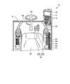
- FIG. 2 is a diagram showing an internal arrangement in the driver's seat.
- FIG. 3 is a block diagram showing a schematic configuration of a control system of the wheeled hydraulic excavator.
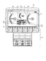
- FIG. 4 is a diagram showing a schematic configuration of the monitor.
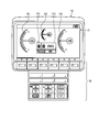
- FIG. 5 is a diagram showing a display screen configuration of the monitor when the driving mode is switched.
- FIG. 6 is a state transition diagram of travel mode switching.
- FIG. 7 is a diagram showing transition of the display screen when switching from the 2WS mode to the 4WS-R mode.
- FIG. 8 is a diagram illustrating transition of the display screen when switching from the 2WS mode to the street mode.
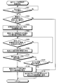
- FIG. 9 is a flowchart showing a traveling mode switching display control processing procedure by the monitor controller.
- FIG. 1 is a side view showing a wheel-type hydraulic excavator 1 which is an example of a work machine including a display device for a work machine according to an embodiment of the present invention.
- a wheel-type hydraulic excavator 1 includes a lower traveling body 2 having a front wheel 11 attached to the front left and right of the vehicle and a rear wheel 12 attached to the rear left and right of the vehicle, and a lower traveling body 2.
- the upper revolving unit 3 provided on the upper revolving unit 3 and the working machine 4 mounted on the upper revolving unit 3 are provided.
- the lower traveling body 2 may be provided with an outrigger for stabilizing the vehicle body during work such as excavation by the wheeled hydraulic excavator 1, a blade for extruding or leveling earth and sand, and the like.
- the work machine 4 has a boom 41, an arm 42, and a bucket 43.
- the boom 41, the arm 42, and the bucket 43 are each flexibly driven by the expansion / contraction drive of the hydraulic cylinder 44.
- the boom 41 has a two-piece structure having two booms 45 and 46.
- a power container such as an engine 33 (see FIG. 3), a hydraulic pump 34 (see FIG. 3), a radiator, and an oil cooler is mounted behind the upper swing body 3.
- a counterweight 32 is attached to the rear end of the upper swing body 3. Further, a hydraulic oil tank or the like is disposed on the front left side of the upper swing body 3.
- a cab 31 is arranged on the right front side of the upper swing body 3. As shown in FIG. 2, the cab 31 has an operator seat 50. Operation levers 51 and 52 are arranged on the left and right sides of the operator seat 50. The operation lever 51 is arranged on the left hand side when the operator is seated on the operator seat 50. The operation lever 52 is disposed on the right hand side when the operator is seated on the operator seat 50. The operation lever 51 corresponds to the turning operation of the upper revolving body 3 and the operation of the arm 42. When the operating lever 51 is operated left and right, the upper revolving body 3 is turned left and right, and when the operating lever 51 is operated up and down, the arm is operated. 42 rotates in the front-rear direction.
- the operation lever 52 corresponds to the operation of the boom 41 and the operation of the bucket 43.
- the operation lever 52 is operated to the left and right, the bucket 43 rotates in the excavation and soil removal direction, and when the operation lever 52 is operated up and down, the boom is operated. 41 rotates in the vertical direction.
- the combination of the operation of the operation levers 51 and 52 and which work machine operates is not limited to that of the present embodiment.
- a steering handle 53, a shift lever 54, and a pedal group 55 are provided in front of the operator seat 50.
- the pedal group 55 includes an accelerator pedal 55a and a brake pedal 55b.
- the steering handle 53 steers the front wheels 11 and the rear wheels 12 according to the travel mode.
- the shift lever 54 performs a selection operation of forward travel, neutral, and reverse travel.
- the accelerator pedal 55a performs engine control according to the depression operation.
- the brake pedal 55b activates a brake (not shown) according to the stepping operation to stop the front wheels 11 and the rear wheels 12.
- the above-described travel modes are classified into 2WS (two-wheel steering) mode M1, 4WS-R (antiphase four-wheel steering) mode M2, 4WS-C (in-phase four-wheel steering) mode M3, and street. It is described as mode M4.
- the method of steering the front wheels 11 and the rear wheels 12 according to the steering of the steering wheel 53 in each traveling mode is as described above.
- the front wheels are controlled in accordance with the steering angle of the steering handle 53, but the rear wheels remain facing the upper swing body 3 regardless of the steering angle of the steering handle 53.
- the steering control is similar to that of a general automobile.
- front wheel steering is the same as in the 2WS mode, but the rear wheel steering is controlled in the opposite direction to the steering direction of the front wheels, so it is smaller than the 2WS mode.
- the front wheel steering is the same as in the 2WS mode, but the rear wheel steering is controlled in the same direction as the steering direction of the front wheels. It is possible to do so-called crab running without changing.
- a kind of driving mode it is not restricted to the thing of this embodiment.
- the console on the right side of the cab 31 is provided with a suspension lock switch 57, travel mode changeover switches 58 and 59, a street mode changeover switch 60, and a speed mode changeover switch 61 as examples of various changeover switches.
- the suspension lock switch 57 is a switch for locking the expansion and contraction of a suspension cylinder 81 (see FIG. 3) provided in the lower traveling body 2, and may be, for example, an ON / OFF switching type switch. This is because, by locking the suspension cylinder 81, the workability is ensured by suppressing the swinging of the vehicle body due to the change of the center of gravity during the work using the work machine 4.
- the travel mode changeover switches 58 and 59 are switches for selecting / switching the 2WS mode M1, 4WS-R mode M2, and 4WS-C mode M3.
- the travel mode changeover switch 58 includes “2WS” and “4WS”.
- the travel mode switch 59 may be a switch that switches between “4WS-R” and “4WS-C”. That is, if the travel mode changeover switch 58 is in the “2WS” position, the travel mode changeover switch 59 is set to the 2WS mode M1 regardless of the position, and if the travel mode changeover switch 58 is in the “4WS” position.
- the travel mode may be determined depending on which position of the travel mode selector switch 59 is “4WS-R” or “4WS-C”.
- the street mode changeover switch 60 is a switch for making a request for switching to the street mode M4, and may be, for example, an ON / OFF switchable switch. A request for switching to the street mode is issued in the ON state, and a request for switching to the street mode is not issued in the OFF state.
- the speed mode changeover switch 61 may be a switch for switching, for example, three speed modes for changing the upper limit of the vehicle speed, a Hi (high speed) mode, a Low (low speed) mode, and a Creep (slow speed) mode.
- the high-speed mode is a mode for traveling at a speed of 30 km / h or less, for example.
- the low speed mode is a mode for traveling at a speed of 10 km / h or less, for example. Further, the slow speed mode is a mode for traveling at a speed of 4.5 km / h or less, for example. Note that the configuration of the various switches is not limited to that of the present embodiment.
- a monitor 70 is arranged in front of the cab 31.
- the monitor 70 includes a display unit (output unit) 71 that displays various information, and an operation unit 72 for operating information displayed on the display unit (output unit) 71.
- FIG. 3 is a block diagram showing a schematic configuration of the control system of the wheeled hydraulic excavator 1.
- the main controller C10, the monitor controller C11, and the engine controller C12 are connected to a CAN 100 that is an in-vehicle network.
- the CAN 100 is connected to a suspension lock switch 57, travel mode changeover switches 58 and 59, a street mode changeover switch 60, and a speed mode changeover switch 61.
- the monitor controller C11 transmits / receives information to / from various switches such as the travel mode changeover switches 58 and 59 and other controllers such as the main controller C10 and the engine controller C12 via the CAN 100 and to the monitor 70 based on the information. Display control.
- the monitor controller C11 constitutes a “display controller (output controller)”, and the monitor controller C11 and the monitor 70 constitute a “display device (output device)”. Specific display contents displayed on the monitor will be described later.
- the engine controller C12 exchanges information with other controllers via the CAN 100, and controls the fuel injection device 33a to control the output of the engine 33.
- the output shaft of the engine 33 is connected to the input shaft of the hydraulic pump 34.
- the hydraulic pump 34 is driven to rotate by driving the engine 33.
- the hydraulic oil discharged from the hydraulic pump 34 is supplied to the traveling-related, turning-related, and working machine-related hydraulic devices via the main valve 35.
- the hydraulic oil that has passed through the main valve 35 is supplied to the hydraulic motor 21.
- the hydraulic motor 21 is rotationally driven by the supplied hydraulic oil and rotationally drives the rear wheel 12 via the transmission 22.
- suspension cylinders 81 are provided at the suspension portions of the front wheels 11 and the rear wheels 12. Hydraulic fluid is supplied from the main valve 35 to the suspension cylinder 81 via the suspension lock valve 82.
- the main controller C10 is connected to a suspension lock solenoid (not shown) incorporated in the suspension lock valve 82. When the main controller C10 receives a signal that the suspension lock switch 57 is switched to the ON side, the suspension controller drives the suspension lock solenoid. 82 is closed, the flow path between the main valve 35 and the suspension cylinder 81 is shut off, and the damper function due to the expansion and contraction of the suspension cylinder 81 is locked.
- the front wheels 11 and the rear wheels 12 are steered by known steering mechanisms 83 and 84.
- the steering mechanisms 83 and 84 have a steering hydraulic cylinder (not shown).
- the hydraulic oil is supplied to the steering hydraulic cylinder via the main valve 35 and the steering valve 36.
- the steering valve 36 performs valve control so that the front wheels 11 and the rear wheels 12 are steered in a predetermined direction with respect to the steering direction of the steering handle 53 according to the traveling mode.
- the main controller C10 is connected to a steering valve solenoid (not shown) incorporated in the steering valve 36.
- the 2WS mode also the street mode
- 4WS-R mode 4WS set by the travel mode changeover switches 58 and 59.
- the steering valve solenoid is driven in accordance with one of the three traveling modes in the -C mode, and the steering in accordance with the set traveling mode is performed via the steering mechanisms 83 and 84.
- the steering amount of the front wheels 11 and the rear wheels 12 is an amount corresponding to the steering angle of the steering handle 53.
- a front wheel facing sensor S1 and a rear wheel facing sensor S2 are connected to the main controller C10.
- “frontal” of the front wheel 11 and the rear wheel 12 is a state in which the steering angle of the front wheel 11 is zero when the front wheel 11 is taken as an example, and the direction of the lower traveling body 2 and the direction of the front wheel 11 are the same. It shows the state you are doing. For example, it can be said that the front wheel 11 and the rear wheel 12 in FIG.
- the front wheel facing sensor S1 detects whether or not the front wheel 11 is facing the front.
- the rear wheel facing sensor S2 detects whether or not the rear wheel 12 is facing the front.
- a vehicle speed sensor S3 is connected to the main controller C10.
- the vehicle speed sensor S3 may calculate the vehicle speed of the wheeled hydraulic excavator 1 by detecting the rotational speed of the front wheels 11, for example.
- the hydraulic oil that has passed through the main valve 35 is supplied to a swing motor 37 provided in the upper swing body 3.
- the turning motor 37 is rotationally driven by the supplied hydraulic oil. Then, the turning motor 37 turns the upper turning body 3 through a swing machinery (not shown).
- the turning position detection sensor S4 is connected to the main controller C10.
- the turning position detection sensor S4 detects whether or not the turning position (turning angle) of the upper turning body 3 with respect to the lower traveling body 2 is directly facing.
- the “facing” of the upper swing body 3 indicates a state in which the direction of the work implement 4 provided on the upper swing body 3 is coincident with the straight traveling direction L of the lower travel body 2. It will face directly at one place of the 0 ° phase. In addition, you may set so that it may judge facing directly in two places of 0 degree and a 180 degree phase.
- the hydraulic oil is supplied from the main valve 35 to each hydraulic cylinder 44 in the work machine 4.
- a predetermined amount of hydraulic oil is supplied to the hydraulic cylinder 44 (for example, boom cylinder) corresponding to the predetermined work machine 4 (for example, boom 41).
- the hydraulic cylinder expands and contracts, and the predetermined working machine 4 rotates.
- an engine water temperature gauge G1 indicating the coolant temperature of the engine is displayed.
- a fuel level gauge G3 indicating the level of the remaining amount of fuel is displayed.
- a hydraulic oil temperature gauge G2 indicating the oil temperature of the hydraulic oil in the hydraulic circuit is displayed on the upper center portion of the display unit 71 smaller than the engine water temperature gauge G1 and the fuel level gauge G3.
- an area E1 is displayed, which is an area for displaying information related to driving mode switching.
- the icon I10 displayed in the area E1 indicates state information that the current travel mode is the 2WS mode.
- FIG. 5 shows that although a request for switching to the 4WS-R mode is output from the state of the 2WS mode in FIG. 4 by operating the travel mode changeover switches 58 and 59, the predetermined condition is not satisfied.
- the icon I1 is a case where a switching request is output from a certain traveling mode to another traveling mode, and since all of the plurality of conditions for switching to another traveling mode are not satisfied, under which conditions the unsatisfied conditions are satisfied It is an icon for displaying individual condition information indicating whether or not there is.
- three small icons are displayed in the area of the icon I1 as unsatisfied conditions, that is, there are three unsatisfied conditions. Details of specific conditions will be described later.
- the icon I2 displays state information indicating that the switching of the driving mode is not completed because the condition is not satisfied when one or more conditions for switching to another driving mode are not satisfied.
- the front wheel 11 and the rear wheel 12 are respectively displayed.
- the front wheel 11 or the rear wheel 12 facing the front is displayed in green and is not facing the front.
- the front wheels 11 or the rear wheels 12 that are not facing each other are displayed in yellow. Thereby, the operator can determine whether the front wheels 11 and the rear wheels 12 are facing each other at a glance.
- the selection state of the shift lever 54 is displayed on the icon I4, and in the example of FIG. 5, the neutral state is indicated.
- the icon I5 indicates the suspension lock state. In the example of FIG. 5, the suspension lock is activated, that is, the suspension lock switch 57 is turned on. If the suspension lock is not activated, the color of the icon I5 may be changed.
- the icon I6 displays the state of the request for switching to the street mode M4.
- the state in which the request for switching to the street mode M4 is issued that is, the street mode switch 60 is ON. It shows that it has become.
- the icon I6 may be blank when a request for switching to the street mode M4 has not been issued.
- FIG. 6 is a state transition diagram of travel mode switching. This state transition is performed by the main controller C10 functioning as a “switching control unit” in the travel mode. As shown in FIG. 6, the 2WS mode M1, 4WS-R mode M2, and 4WS-C mode M3 can be switched to each other. On the other hand, the street mode M4 can be switched only between the 2WS mode M1.
- Switching from the 4WS-R mode M2, the 4WS-C mode M3, and the street mode M4 to the 2WS mode M1 is performed when all the following conditions A are satisfied.
- the selection of the 2WS mode M1 is based on the condition that the travel mode changeover switch 58 (the switch for switching between 2WS and 4WS) is in the “2WS” state (the travel mode changeover switch 59 may be in any position). ). Further, as the predetermined vehicle speed, any vehicle speed may be set, but it may be set to a vehicle speed close to approximately 0 km / h. This is because if the traveling mode can be switched during traveling, the rudder angle of the rear wheel 12 may suddenly change during traveling, and the behavior of the vehicle against the operator's intention may occur. Further, the front wheel 11 and the rear wheel 12 facing each other is whether or not the front wheel 11 and the rear wheel 12 are “facing” as described above using the front wheel facing sensor S2 and the rear wheel facing sensor S3. Is detected.
- Condition B 4WS-R mode M2 selection + predetermined vehicle speed or less + front wheel 11 and rear wheel 12 facing + selection of street mode M4
- the selection of the 4WS-R mode M2 means that the travel mode changeover switch 58 (switch for switching between 2WS and 4WS) is set to the state of “4WS”, and the travel mode changeover switch 59 (4WS-R and 4WS-C is changed). This is based on the condition that the switch to be switched is in the “4WS-R” state.
- the deselection of the street mode M4 indicates that a request for switching to the street mode M4 has not been issued, that is, the street mode switch 60 is in an OFF state.
- Condition C Selection of 4WS-C mode M3 + predetermined vehicle speed or less + front wheel 11 and rear wheel 12 facing + selection cancellation of street mode M4 + selection of speed mode other than Hi mode
- the selection of the 4WS-C mode M3 means that the travel mode changeover switch 58 (switch for switching between 2WS and 4WS) is set to the state of “4WS”, and the travel mode changeover switch 59 (4WS-R and 4WS-C is changed). The switch is to be in the “4WS-C” state.
- “Selection of speed mode other than Hi mode (high speed mode)” is that the speed mode is set to Low mode or Creep mode. This is because when the vehicle is operated in the 4WS-C mode, that is, in the crab running, the direction of the operator seat 50 may not coincide with the traveling direction of the vehicle, and the high speed running during the crab running is restricted.
- the switching from the 2WS mode M1 to the street mode M4 is switched when the following condition D is satisfied after the street mode M4 is selected by the travel mode switch 58.
- Condition D Selection of street mode M4 + 2WS mode state + predetermined vehicle speed or less + facing the upper turning body 3 + release of suspension lock
- the selection of the street mode M4 is based on the condition that the street mode changeover switch 60 is in the ON state.
- the 2WS mode state is on condition that the current travel mode is the 2WS mode.
- whether or not the upper swing body 3 is directly facing is determined by the swing position detection sensor S6 as to whether or not the upper swing body 3 is “facing” as described above.
- the suspension lock is released on condition that the suspension lock switch 57 is in the released state. This is because if the vehicle travels on a public road with the suspension lock activated, a shock due to the rattling of the road surface is transmitted to the operator.
- the driving mode switching is not completed because one or more conditions are not satisfied, and the other driving
- the travel mode before the selection of another travel mode is maintained. For example, when the current travel mode is the 2WS mode M1, if the selection is made to the 4WS-R mode M2 after the 4WS-R mode M2 is selected and before the switching is completed, the 2WS mode M1 is changed. maintain.
- FIG. 7 is a diagram showing transition of the display screen when switching from the 2WS mode to the 4WS-R mode.
- the display screen 200 in the 2WS mode displays an icon I10 as state information indicating the 2WS mode that is the current travel mode. Further, since the icon I6 is displayed, it can be seen that the street mode changeover switch 60 is ON.
- the travel mode changeover switch 58 (a switch for switching between “2WS” and “4WS”) is set to “4WS”
- the travel mode changeover switch 59 (a switch for switching between “4WS-R” and “4WS-C”) is set to “4WS”.
- the monitor controller C11 determines whether all the plurality of switching conditions (condition B) for switching to the 4WS-R mode are satisfied. If there are switching conditions that are not satisfied, for example, display Like the screen 201, the icons I11 to I13 corresponding to the switching conditions that are not satisfied are displayed as individual condition information, and the icon I2 indicating that the switching conditions are not satisfied is displayed as status information.
- the icon I11 satisfies the condition “below the predetermined vehicle speed” in the condition B described above, the icon I12 satisfies the condition “facing the front wheel 11”, and the icon I13 satisfies the condition “deselection of the street mode M4”. It shows no. Based on the individual condition information, when the operator performs a deceleration operation to satisfy the condition of “below the predetermined vehicle speed”, the icon I11 disappears as shown in the display screen 202, and the operator makes the condition of “below the predetermined vehicle speed” Can be recognized.
- the icon I12 disappears as shown in the display screen 203, and the operator It can be recognized that the “pair” condition is satisfied.
- the condition “deselection of the street mode M4” is satisfied by turning off the street mode switch 60, as shown in the display screen 204, all the switching conditions are satisfied.
- An icon I15 indicating that the mode has been switched to the 4WS-R mode is displayed.
- an icon I7 (blank) indicating that the street mode changeover switch 60 is OFF is displayed instead of the icon I6.
- the traveling mode changeover switch 58 is switched to “2WS”, that is, the selection of the 4WS-R mode is canceled, the current traveling mode 2WS mode is maintained.
- the display transitions to the display screen 200 indicating the 2WS mode.
- FIG. 8 is a diagram showing the transition of the display screen when switching from the 2WS mode to the street mode.
- the display screen 300 in the 2WS mode displays an icon I20 as state information indicating the 2WS mode that is the current travel mode, similarly to the display screen 200.
- the suspension lock is activated (icon I5 is displayed) and the street mode changeover switch 60 is OFF (icon I7 is displayed).
- the monitor controller C11 determines whether or not all the plurality of changeover conditions (condition D) for changing to the street mode are satisfied. If there is a switching condition that is not present, for example, the icons I21 to I23 that are individual condition information may be displayed in the area of the icon I7 as in the display screen 301. Since the street mode is the same type as the 2WS mode, the icon I20 may be left as it is. In addition, an icon I21 indicating that switching to the street mode has not been completed may be displayed as one piece of individual condition information.
- the icon I22 indicates that the “upward turning body 3 is directly facing”, and the icon I23 indicates that the condition of “release of suspension lock” is not satisfied.
- the icon I22 indicating that the upper swing body 3 is not facing is disappeared, A screen like the display screen 302 is displayed. Further, when the suspension lock is released by switching the suspension lock switch 57 to OFF in the state of the display screen 302, the icon I23 indicating that the suspension lock is not released disappears, and all the switching conditions are satisfied. Therefore, the icon I21 also disappears, and an icon I6 that is state information indicating that the mode has been switched to the street mode is displayed in the area where the individual condition information is displayed.
- the operator recognizes that the mode has been changed to the street mode by displaying the icons I20 and I6.
- an icon I8 (changed color of the icon I5) indicating a suspension lock release state is displayed.
- step S101 it is determined whether or not another travel mode has been selected. Whether or not another travel mode has been selected is determined based on the selection states of the travel mode changeover switches 58 and 59 and the street mode changeover switch 60. If the current travel mode is the 2WS mode M1, this determination is made when no other travel mode such as the 4WS-R mode M2, the 4WS-C mode M3, or the street mode M4 is selected (No in step S101). Repeat the process. On the other hand, if another travel mode is selected (step S101, Yes), the process proceeds to the next step.
- step S102 it is determined whether there are any unsatisfied conditions among a plurality of switching conditions for the selected other travel mode.
- step S102 Yes
- status information indicating that the switching condition is not satisfied is displayed (step S103).
- status information indicating that switching from the 2WS mode to the 4WS-R mode cannot be performed is displayed.
- individual condition information indicating the content of the switching condition that is not satisfied is displayed (step S104). For example, as shown by icons I11, I12, and I13 in the display screen 201 of FIG. 7, three pieces of individual condition information are displayed.
- the monitor controller C11 determines whether there is a satisfied switching condition among the unsatisfied switching conditions (step S106).
- the display of the individual condition information is deleted (step S107). For example, in the state of the display screen 201 in FIG. 7, when a deceleration operation is performed so as to satisfy the condition of a predetermined vehicle speed or less, the display of the icon I ⁇ b> 11 that is the individual condition information is deleted and the display screen 202 is displayed as shown in FIG. It becomes a screen.
- the process proceeds to Step S108.
- step S108 Deselection of the selected other travel mode means that the travel mode changeover switch 58, 59 is used so that the travel mode before the selection of another travel mode by the travel mode changeover switches 58, 59, that is, the current travel mode is maintained. The case where 59 is operated again is shown.
- the display returns to the current travel mode before the selection of the other travel mode, so that the status information indicating that the current travel mode is displayed (Step S109), the process returns to step S101 and the above-described processing is repeated.
- the selected 4WS-R mode is deselected in the state of the display screen 202 in FIG. 6, the display returns to the display screen 200, and the icon I10, which is state information indicating that the current running mode (2WS mode) is present. Is displayed.
- step S108 determines whether or not all switching conditions are satisfied.
- step S110 Yes
- step S110 Yes
- step S110 Yes
- step S110 Yes
- step S110 Yes
- step S110 Yes
- step S110 Yes
- step S110 Yes
- step S110 Yes
- step S110 Yes
- step S110 Yes
- step S110 Yes
- step S110 Yes
- step S110 Yes
- step S110 Yes
- step S110 Yes
- step S111 for example, an icon I15 of status information is displayed as in the display screen 203 of FIG. 7, and an icon of individual condition information indicating a condition that is not satisfied with the display of this icon I15 is also displayed. Erased.
- step S110 No
- step S106 if all the switching conditions are not satisfied (step S110, No) the process proceeds to step S106 and this loop is repeated.
- step S103 when there is no unsatisfied condition among the plurality of switching conditions (No in step S103), since all the switching conditions are satisfied, the process proceeds to step S111 and immediately other Status information indicating that the mode has been switched to the travel mode is displayed. Then, it transfers to step S101 and repeats the process mentioned above.
- the display of the individual condition information is sequentially deleted every time the switching condition is satisfied.
- the present invention is not limited to this, and when all the conditions are satisfied, all the individual condition information is collectively displayed. Then, it may be erased.
- the individual condition information and the state information may be not only an image display such as an icon but also a character display such as a message. Furthermore, a lamp corresponding to the individual condition information and the state information may be displayed in a lit state. Depending on the contents of the individual condition information and the state information, the color of the lamp and icon and other display modes (such as brightness / darkness, transmittance, presence / absence of blinking) may be changed. Moreover, the aspect by audio
- displaying all icons corresponding to unsatisfied conditions may be cumbersome, it may be displayed in a more simplified form. For example, when there are a plurality of conditions that are not satisfied, only a part of the conditions, for example, only icons corresponding to one or two conditions may be displayed. In this case, the display may be made based on the priority order of items set in advance.
- the travel mode changeover switches 58 and 59 and the street mode changeover switch 60 are used as the switches for switching the travel modes.
- any type of switch for mode switching may be used. . It may be a button type, a dial type, or a touch panel type.
- the main controller C10 may store the travel mode when the key switch is off, and may control the previous travel mode stored when the key switch is on.
- a predetermined traveling mode for example, the 2WS mode may be selected whenever the key is turned on.
- the type and form of sensors such as the front wheel facing sensor S1, the rear wheel facing sensor S2, the vehicle speed sensor S3, and the turning position detecting sensor S4 may be any.
- the rear-wheel drive vehicle via the transmission 22 has been described as an example, but any drive system such as front-wheel drive or four-wheel drive may be used. Further, the present invention may be applied not only to a wheel-type hydraulic excavator but also to any work machine such as a crawler-type hydraulic excavator, a wheel loader, a bulldozer, and a dump truck.
- the four travel modes are used.
- the present invention is not limited to modes related to travel, and may be applied to any “mode” switching. Any number of modes may be provided as long as it is two or more.
- the outrigger installation release may be added as a mode switching condition.
- the individual condition information may be displayed instead of the display in an area where something was displayed until the mode switching as in the above embodiment. It is also possible to display individual condition information in an area where nothing has been displayed until then, or to display individual condition information so that it partially overlaps the area where something was displayed before the mode was switched. May be.
Landscapes
- Engineering & Computer Science (AREA)
- Mechanical Engineering (AREA)
- Chemical & Material Sciences (AREA)
- Combustion & Propulsion (AREA)
- Transportation (AREA)
- Mining & Mineral Resources (AREA)
- Civil Engineering (AREA)
- General Engineering & Computer Science (AREA)
- Structural Engineering (AREA)
- Steering-Linkage Mechanisms And Four-Wheel Steering (AREA)
- Component Parts Of Construction Machinery (AREA)
Abstract
Description
まず、図1は、本発明の実施の形態にかかる作業機械の表示装置を含む作業機械の一例であるホイール式油圧ショベル1を示す側面図である。図1に示すように、ホイール式油圧ショベル1は、車両の前方左右に取り付けられた前輪11と車両の後方左右に取り付けられた後輪12とを有した下部走行体2と、下部走行体2上に旋回自在に設けられた上部旋回体3と、上部旋回体3に装着された作業機4とを有する。なお、下部走行体2には、ホイール式油圧ショベル1による掘削等の作業時に車体を安定させるためのアウトリガーや、土砂を押し出したり、均したりするためのブレードなどを設けるようにしてもよい。
次に、図4を参照してモニタ70の概要について説明する。表示部71の左側には、エンジンの冷却水の水温を示すエンジン水温ゲージG1が表示される。また、表示部71の右側には、燃料の残量のレベルを示す燃料レベルゲージG3が表示される。さらに、表示部71の中央上部には、油圧回路内の作動油の油温を示す作動油温ゲージG2が、エンジン水温ゲージG1及び燃料レベルゲージG3に比して小さく表示される。
図6は、走行モード切替の状態遷移図である。この状態遷移は、走行モードの「切替制御部」として機能するメインコントローラC10によって行われる。図6に示すように2WSモードM1,4WS-RモードM2,4WS-CモードM3の間は、相互に切替可能である。一方、ストリートモードM4は、2WSモードM1との間でのみ、切替可能である。
条件A:2WSモードM1の選択+所定車速以下+前輪11及び後輪12の正対
条件B:4WS-RモードM2の選択+所定車速以下+前輪11及び後輪12の正対+ストリートモードM4の選択解除
条件C:4WS-CモードM3の選択+所定車速以下+前輪11及び後輪12の正対+ストリートモードM4の選択解除+速度モードがHiモード以外の選択
条件D:ストリートモードM4の選択+2WSモード状態+所定車速以下+上部旋回体3の正対+サスペンションロックの解除
図7は、2WSモードから4WS-Rモードに切り替える場合の表示画面の遷移を示す図である。図7に示すように、2WSモードのときの表示画面200は、現在の走行モードである2WSモードを示す状態情報としてアイコンI10を表示する。また、アイコンI6が表示されていることから、ストリートモード切替スイッチ60がONとなっていることがわかる。
次に、図9に示すフローチャートを参照して、モニタコントローラC11による走行モード切替表示制御処理手順について説明する。
2 下部走行体
3 上部旋回体
4 作業機
11 前輪
12 後輪
21 油圧モータ
22 トランスミッション
31 運転室
32 カウンタウェイト
33 エンジン
33a 燃料噴射装置
34 油圧ポンプ
35 メインバルブ
36 ステアリングバルブ
37 旋回モータ
38 旋回ブレーキ
41,45,46 ブーム
42 アーム
43 バケット
44 油圧シリンダ
50 オペレータシート
51,52 操作レバー
53 操舵ハンドル
54 シフトレバー
55 ペダル群
55a アクセルペダル
55b ブレーキペダル
57 サスペンションロックスイッチ
58,59 走行モード切替スイッチ
60 ストリートモード切替スイッチ
61 速度モード切替スイッチ
70 モニタ
71 表示部
72 操作部
81 サスペンションシリンダ
82 サスペンションロックバルブ
83,84 ステアリング機構
200~203,301~303 表示画面
C10 メインコントローラ
C11 モニタコントローラ
C12 エンジンコントローラ
E1
G1 エンジン水温ゲージ
G2 作動油温ゲージ
G3 燃料レベルゲージ
I1~I8,I10~I13,I15,I20~I23 アイコン
S1 前輪正対センサ
S2 後輪正対センサ
S3 車速センサ
S4 旋回位置検出センサ
Claims (9)
- 第1のモードと第2のモードとを有し、前記第1のモードから前記第2のモードに切り替えるための複数の条件を満たした場合に、前記第1のモードから前記第2のモードに切り替える切替制御部を備えた作業機械の出力装置であって、
前記複数の条件の内2つ以上の条件を満たしていない場合、当該満たしていない2つ以上の条件にそれぞれ対応した個別条件情報の内、一部もしくはすべての個別条件情報を出力部に出力し、当該満たしていない2つ以上の条件の内ある1つの条件を満たした場合に当該1つの条件に対応する前記個別条件情報の出力を制限する出力制御部を備えたことを特徴とする作業機械の出力装置。 - 前記出力制御部は、前記複数の条件の内1つ以上の条件を満たしていない場合、前記第1のモードから前記第2のモードへの切替の条件を満足しない旨を示す状態情報を前記出力部に出力することを特徴とする請求項1に記載の作業機械の出力装置。
- 前記個別条件情報または前記状態情報の出力は、画像表示、文字表示、点灯表示、または音声出力であることを特徴とする請求項1または2に記載の作業機械の出力装置。
- 前記画像表示、前記文字表示、または前記点灯表示は、前記個別条件情報または前記状態情報の内容に応じて、色及び/または表示態様を変化させることを特徴とする請求項3に記載の作業機械の出力装置。
- 前記第1のモードおよび第2のモードは、それぞれ第1の走行モードおよび第2の走行モードであることを特徴とする請求項1~4のいずれか一つに記載の作業機械の出力装置。
- 前記第1の走行モードおよび前記第2の走行モードは、二輪操舵モード、逆位相四輪操舵モード、同位相四輪操舵モード、公道走行モードのいずれかであることを特徴とする請求項5に記載の作業機械の出力装置。
- 前記個別条件情報または前記状態情報を前記出力部へ表示させる領域として、前記第2のモードに切り替える前まで何か表示されていた領域に当該表示に代えて表示させる、前記第2のモードに切り替える前まで何も表示されていなかった領域に新たに表示させる、もしくは、前記第2のモードに切り替える前まで何か表示されていた領域に一部重なるように表示させることを特徴とする請求項1~6のいずれか一つに記載の作業機械の出力装置。
- 前記出力部は表示部であり、前記出力制御部は表示制御部であり、前記出力装置は表示装置であることを特徴とする請求項1~7のいずれか一つに記載の作業機械の出力装置。
- 第1のモードと第2のモードとを有し、前記第1のモードから前記第2のモードに切り替えるための複数の条件を満たした場合に、前記第1のモードから前記第2のモードに切り替えるステップと、
前記複数の条件の内2つ以上の条件を満たしていない場合、当該満たしていない2つ以上の条件にそれぞれ対応した個別条件情報の内、一部もしくはすべての個別条件情報を出力部に出力するステップと、
当該満たしていない2つ以上の条件の内ある1つの条件を満たした場合に当該1つの条件に対応する前記個別条件情報の出力を制限するステップと、
を含むことを特徴とする作業機械の出力方法。
Priority Applications (3)
| Application Number | Priority Date | Filing Date | Title |
|---|---|---|---|
| KR1020167025836A KR20160148518A (ko) | 2015-05-25 | 2015-05-25 | 작업 기계의 출력 장치 및 작업 기계의 출력 방법 |
| PCT/JP2015/064969 WO2016189634A1 (ja) | 2015-05-25 | 2015-05-25 | 作業機械の出力装置及び作業機械の出力方法 |
| DE112015000969.8T DE112015000969B4 (de) | 2015-05-25 | 2015-05-25 | Ausgabevorrichtung von Arbeitsmaschine und Ausgabeverfahren von Arbeitsmaschine |
Applications Claiming Priority (1)
| Application Number | Priority Date | Filing Date | Title |
|---|---|---|---|
| PCT/JP2015/064969 WO2016189634A1 (ja) | 2015-05-25 | 2015-05-25 | 作業機械の出力装置及び作業機械の出力方法 |
Publications (1)
| Publication Number | Publication Date |
|---|---|
| WO2016189634A1 true WO2016189634A1 (ja) | 2016-12-01 |
Family
ID=57393982
Family Applications (1)
| Application Number | Title | Priority Date | Filing Date |
|---|---|---|---|
| PCT/JP2015/064969 Ceased WO2016189634A1 (ja) | 2015-05-25 | 2015-05-25 | 作業機械の出力装置及び作業機械の出力方法 |
Country Status (3)
| Country | Link |
|---|---|
| KR (1) | KR20160148518A (ja) |
| DE (1) | DE112015000969B4 (ja) |
| WO (1) | WO2016189634A1 (ja) |
Cited By (2)
| Publication number | Priority date | Publication date | Assignee | Title |
|---|---|---|---|---|
| JP2022188496A (ja) * | 2021-06-09 | 2022-12-21 | 井関農機株式会社 | 作業車両 |
| IT202100026735A1 (it) * | 2021-10-19 | 2023-04-19 | Magni Real Estate S R L | Sollevatore telescopico |
Citations (3)
| Publication number | Priority date | Publication date | Assignee | Title |
|---|---|---|---|---|
| JPH0723686U (ja) * | 1993-10-13 | 1995-05-02 | 小松メック株式会社 | 操向モード切換装置 |
| JP2003252230A (ja) * | 2002-02-27 | 2003-09-10 | Hitachi Constr Mach Co Ltd | 作業用車両の操向装置 |
| JP2006050262A (ja) * | 2004-08-04 | 2006-02-16 | Ntt Docomo Inc | 携帯端末 |
Family Cites Families (4)
| Publication number | Priority date | Publication date | Assignee | Title |
|---|---|---|---|---|
| US4175638A (en) * | 1977-10-21 | 1979-11-27 | J. I. Case Company | Electronically controlled four-wheel steering |
| FR2547260B1 (fr) * | 1983-06-10 | 1989-06-30 | Chapuis Laurent | Dispositif de commande de direction d'un vehicule |
| JPH0730456Y2 (ja) * | 1989-05-11 | 1995-07-12 | 株式会社神戸製鋼所 | ホイールクレーンのステアリング制御装置 |
| FR2952893B1 (fr) * | 2009-11-23 | 2016-06-10 | Artec Pulverisation | Systeme de direction pour vehicules a deux ou quatre roues directrices |
-
2015
- 2015-05-25 DE DE112015000969.8T patent/DE112015000969B4/de active Active
- 2015-05-25 WO PCT/JP2015/064969 patent/WO2016189634A1/ja not_active Ceased
- 2015-05-25 KR KR1020167025836A patent/KR20160148518A/ko not_active Ceased
Patent Citations (3)
| Publication number | Priority date | Publication date | Assignee | Title |
|---|---|---|---|---|
| JPH0723686U (ja) * | 1993-10-13 | 1995-05-02 | 小松メック株式会社 | 操向モード切換装置 |
| JP2003252230A (ja) * | 2002-02-27 | 2003-09-10 | Hitachi Constr Mach Co Ltd | 作業用車両の操向装置 |
| JP2006050262A (ja) * | 2004-08-04 | 2006-02-16 | Ntt Docomo Inc | 携帯端末 |
Cited By (4)
| Publication number | Priority date | Publication date | Assignee | Title |
|---|---|---|---|---|
| JP2022188496A (ja) * | 2021-06-09 | 2022-12-21 | 井関農機株式会社 | 作業車両 |
| JP7643193B2 (ja) | 2021-06-09 | 2025-03-11 | 井関農機株式会社 | 作業車両 |
| IT202100026735A1 (it) * | 2021-10-19 | 2023-04-19 | Magni Real Estate S R L | Sollevatore telescopico |
| WO2023066744A1 (en) * | 2021-10-19 | 2023-04-27 | Magni Real Estate S.R.L. | Telescopic boom lift |
Also Published As
| Publication number | Publication date |
|---|---|
| KR20160148518A (ko) | 2016-12-26 |
| DE112015000969B4 (de) | 2020-08-13 |
| DE112015000969T5 (de) | 2017-05-18 |
Similar Documents
| Publication | Publication Date | Title |
|---|---|---|
| JP5337220B2 (ja) | 作業機械の表示装置および表示装置を搭載した作業機械 | |
| JP6648296B2 (ja) | 作業車両 | |
| JP6949483B2 (ja) | 作業機 | |
| JP2019019522A (ja) | 建設機械 | |
| JP4569739B2 (ja) | 建設機械の表示装置 | |
| WO2022176991A1 (ja) | 作業機械の制御システム、作業機械の制御方法、および作業機械 | |
| JP6577433B2 (ja) | ホイール式油圧ショベル | |
| JP5011150B2 (ja) | 作業車両の表示装置 | |
| KR101491942B1 (ko) | 건설중장비의 트랜스미션 컷 오프 제어장치 및 제어방법 | |
| KR20160148518A (ko) | 작업 기계의 출력 장치 및 작업 기계의 출력 방법 | |
| JP2019019523A (ja) | 建設機械 | |
| JP7514248B2 (ja) | 作業機械 | |
| EP3647571B1 (en) | Work machine | |
| WO2019176453A1 (ja) | 作業車両 | |
| CN116368277A (zh) | 作业机械、作业机械的控制装置以及作业机械的控制方法 | |
| CN105026655B (zh) | 轮式作业车辆的状态信息显示装置、维护用画面的显示方法 | |
| KR20170077537A (ko) | 작업기계의 유압모터 제어 시스템 및 방법 | |
| JP6852257B2 (ja) | 作業車両 | |
| JP2021024330A (ja) | 作業車両 | |
| JP2009096376A (ja) | ホイール式建設機械 | |
| JP2024094117A (ja) | 作業車両の操作装置、及び作業車両 | |
| JP2024094118A (ja) | 作業車両の支援装置、及び作業車両 | |
| JP2024094116A (ja) | 作業車両の操作装置、及び作業車両 | |
| JP2024094119A (ja) | 作業車両の支援装置、及び作業車両 | |
| WO2016181712A1 (ja) | 作業機械の前後進誤作動報知装置 |
Legal Events
| Date | Code | Title | Description |
|---|---|---|---|
| ENP | Entry into the national phase |
Ref document number: 20167025836 Country of ref document: KR Kind code of ref document: A |
|
| WWE | Wipo information: entry into national phase |
Ref document number: 112015000969 Country of ref document: DE |
|
| 121 | Ep: the epo has been informed by wipo that ep was designated in this application |
Ref document number: 15893269 Country of ref document: EP Kind code of ref document: A1 |
|
| 122 | Ep: pct application non-entry in european phase |
Ref document number: 15893269 Country of ref document: EP Kind code of ref document: A1 |
|
| NENP | Non-entry into the national phase |
Ref country code: JP |