WO2016189614A1 - イオンミリング装置、及びイオンミリング方法 - Google Patents
イオンミリング装置、及びイオンミリング方法 Download PDFInfo
- Publication number
- WO2016189614A1 WO2016189614A1 PCT/JP2015/064884 JP2015064884W WO2016189614A1 WO 2016189614 A1 WO2016189614 A1 WO 2016189614A1 JP 2015064884 W JP2015064884 W JP 2015064884W WO 2016189614 A1 WO2016189614 A1 WO 2016189614A1
- Authority
- WO
- WIPO (PCT)
- Prior art keywords
- ion
- gas
- ion gun
- sample
- gas injection
- Prior art date
- Legal status (The legal status is an assumption and is not a legal conclusion. Google has not performed a legal analysis and makes no representation as to the accuracy of the status listed.)
- Ceased
Links
Images










Classifications
-
- H—ELECTRICITY
- H01—ELECTRIC ELEMENTS
- H01J—ELECTRIC DISCHARGE TUBES OR DISCHARGE LAMPS
- H01J27/00—Ion beam tubes
- H01J27/02—Ion sources; Ion guns
- H01J27/04—Ion sources; Ion guns using reflex discharge, e.g. Penning ion sources
-
- H—ELECTRICITY
- H01—ELECTRIC ELEMENTS
- H01J—ELECTRIC DISCHARGE TUBES OR DISCHARGE LAMPS
- H01J37/00—Discharge tubes with provision for introducing objects or material to be exposed to the discharge, e.g. for the purpose of examination or processing thereof
- H01J37/02—Details
- H01J37/04—Arrangements of electrodes and associated parts for generating or controlling the discharge, e.g. electron-optical arrangement or ion-optical arrangement
- H01J37/08—Ion sources; Ion guns
-
- H—ELECTRICITY
- H01—ELECTRIC ELEMENTS
- H01J—ELECTRIC DISCHARGE TUBES OR DISCHARGE LAMPS
- H01J37/00—Discharge tubes with provision for introducing objects or material to be exposed to the discharge, e.g. for the purpose of examination or processing thereof
- H01J37/02—Details
- H01J37/24—Circuit arrangements not adapted to a particular application of the tube and not otherwise provided for
- H01J37/243—Beam current control or regulation circuits
-
- H—ELECTRICITY
- H01—ELECTRIC ELEMENTS
- H01J—ELECTRIC DISCHARGE TUBES OR DISCHARGE LAMPS
- H01J37/00—Discharge tubes with provision for introducing objects or material to be exposed to the discharge, e.g. for the purpose of examination or processing thereof
- H01J37/30—Electron-beam or ion-beam tubes for localised treatment of objects
-
- H—ELECTRICITY
- H01—ELECTRIC ELEMENTS
- H01J—ELECTRIC DISCHARGE TUBES OR DISCHARGE LAMPS
- H01J37/00—Discharge tubes with provision for introducing objects or material to be exposed to the discharge, e.g. for the purpose of examination or processing thereof
- H01J37/30—Electron-beam or ion-beam tubes for localised treatment of objects
- H01J37/302—Controlling tubes by external information, e.g. program control
-
- H—ELECTRICITY
- H01—ELECTRIC ELEMENTS
- H01J—ELECTRIC DISCHARGE TUBES OR DISCHARGE LAMPS
- H01J37/00—Discharge tubes with provision for introducing objects or material to be exposed to the discharge, e.g. for the purpose of examination or processing thereof
- H01J37/30—Electron-beam or ion-beam tubes for localised treatment of objects
- H01J37/305—Electron-beam or ion-beam tubes for localised treatment of objects for casting, melting, evaporating, or etching
-
- H—ELECTRICITY
- H01—ELECTRIC ELEMENTS
- H01J—ELECTRIC DISCHARGE TUBES OR DISCHARGE LAMPS
- H01J37/00—Discharge tubes with provision for introducing objects or material to be exposed to the discharge, e.g. for the purpose of examination or processing thereof
- H01J37/30—Electron-beam or ion-beam tubes for localised treatment of objects
- H01J37/305—Electron-beam or ion-beam tubes for localised treatment of objects for casting, melting, evaporating, or etching
- H01J37/3053—Electron-beam or ion-beam tubes for localised treatment of objects for casting, melting, evaporating, or etching for evaporating or etching
-
- H—ELECTRICITY
- H01—ELECTRIC ELEMENTS
- H01J—ELECTRIC DISCHARGE TUBES OR DISCHARGE LAMPS
- H01J2237/00—Discharge tubes exposing object to beam, e.g. for analysis treatment, etching, imaging
- H01J2237/006—Details of gas supplies, e.g. in an ion source, to a beam line, to a specimen or to a workpiece
-
- H—ELECTRICITY
- H01—ELECTRIC ELEMENTS
- H01J—ELECTRIC DISCHARGE TUBES OR DISCHARGE LAMPS
- H01J2237/00—Discharge tubes exposing object to beam, e.g. for analysis treatment, etching, imaging
- H01J2237/02—Details
- H01J2237/022—Avoiding or removing foreign or contaminating particles, debris or deposits on sample or tube
-
- H—ELECTRICITY
- H01—ELECTRIC ELEMENTS
- H01J—ELECTRIC DISCHARGE TUBES OR DISCHARGE LAMPS
- H01J2237/00—Discharge tubes exposing object to beam, e.g. for analysis treatment, etching, imaging
- H01J2237/06—Sources
- H01J2237/08—Ion sources
Definitions
- the present invention relates to an ion milling apparatus and an ion milling method.
- An ion milling method is known as one of sample cross-section preparation methods for the purpose of analysis with a scanning electron microscope.
- An ion milling apparatus that performs the ion milling method includes a sample chamber, an ion gun, a sample stage, a vacuuming mechanism, and the like.
- a Penning discharge type ion gun As an ion gun applicable to an ion milling apparatus, for example, a Penning discharge type ion gun can be mentioned.
- a first chamber which is an ion gun for reducing the amount of sputtered particles deposited on an anode, and an ion generator that ionizes gas in the first chamber to generate ions.
- the ion generation unit is provided with an anode provided in the first chamber, a first cathode that is provided facing the first chamber and emits electrons, and a gas that supplies a gas to the first chamber A supply unit; and a magnetic field generation unit configured to generate a magnetic field in the first chamber, wherein electrons emitted from the first cathode are swirled by the magnetic field generated by the magnetic field generation unit, and the gas supply unit By colliding with the supplied gas, ions are generated in the first chamber, and irregularities are formed in the first region facing the first chamber in the surface of the first cathode.
- An ion source is disclosed.
- the inventor of the present application has earnestly examined the deposits attached to the component parts of the ion gun, and as a result, has obtained the following knowledge.
- the ions generated in the ionization chamber are irradiated to the components of the ion gun such as the cathode and the acceleration electrode. For this reason, a phenomenon (hereinafter referred to as redeposition as appropriate) that sputtered particles are emitted from the component parts of the ion gun and adhere to other component parts occurs inside the ion gun.
- deposits adhering to the components of the ion gun due to redeposition may cause unstable discharge of the ion gun or stop of discharge due to abnormal discharge or short circuit.
- Patent Document 1 can be operated normally for a long time without causing abnormal discharge inside an ion gun as an ion source. However, the invention described in Patent Document 1 does not consider the processing of deposits.
- an object of the present invention is to provide an ion milling apparatus capable of processing a deposit attached with an ion gun and an ion milling method capable of processing a deposit attached with an ion gun.
- the present invention relates to an ion milling device comprising gas injection means for injecting gas toward an ion gun.
- the present invention also relates to moving a deposit adhered to the ion gun by injecting a gas toward the ion gun by gas injection means provided in the ion milling apparatus.
- the ion milling apparatus which can process the deposit which adhered the ion gun, and the ion milling method which can process the deposit which adhered the ion gun can be provided. Problems, configurations, and effects other than those described above will be described in the specification.
- FIG. 1 is a schematic diagram illustrating a configuration of an ion milling apparatus 100 according to the present embodiment.
- An ion milling apparatus 100 includes an ion gun 1, a gas injection nozzle 2, a sample holding system 3, a sample chamber 5, a control system 6, a vacuuming system 7, and a power supply system 8 (see FIG. 2).
- the ion gun 1 and the gas injection nozzle 2 may be present on the side of the sample chamber 5, that is, on the front side of the paper surface.
- the ion gun 1 is an ion source that generates ions inside the ion gun 1 and ejects the generated ions toward the sample S held in the sample holding system 3. Components necessary for generating ions are arranged inside the ion gun 1.
- the sample S is irradiated with an ion beam B (see FIG. 3) made of ions ejected from the ion gun 1 and processed (see FIG. 3).
- the sample holding system 3 includes a sample holding member 31, a sample holding member installation unit 41, and a sample holding member driving unit 44.
- the sample holding member 31 is a member that holds the sample S by any means.
- the sample holding member installation section 41 is configured such that the sample holding member 31 is installed and can be pulled out of the sample chamber 5 when the sample chamber 5 is opened to atmospheric pressure.
- the sample holding member driving unit 44 is configured such that the sample holding member 31 can be driven by a predetermined method. That is, the sample holding system 3 holds the sample S inside the sample chamber 5.
- the control system 6 includes a control unit 61, an operation unit 62, and a display unit 63.
- the control unit 61 controls the irradiation position and range of the ion beam B (see FIG. 3) by controlling the position and orientation of the sample holding system 3.
- the controller 61 is electrically connected to the discharge power supply 81 and the acceleration power supply 82 of the power supply system 8 (see FIG. 2), controls the discharge voltage and the acceleration voltage, and controls the ion beam B (see FIG. 3). Control the current density.
- the control unit 61 is electrically connected to the roughing pump and the high vacuum pump of the vacuuming system 7 and controls the degree of vacuum in the sample chamber 5.
- the operation unit 62 includes, for example, start / stop, operation switches such as vacuum / atmospheric pressure, a discharge / acceleration voltage variable knob, an argon gas flow rate setting knob, a stage mode setting button, a deposit processing start button, and the like.
- the display unit 63 displays the pressure in the sample chamber 5, the discharge current value, the ion beam current value, the argon gas flow rate, the operation mode, the injection gas flow rate, the injection gas injection frequency, the discharge instability warning, the short circuit warning, and the like. indicate.
- the display unit 63 includes, for example, a light emitting diode, a liquid crystal panel, an organic electroluminescence panel, and the like.
- the sample chamber 5 is a space (vacuum chamber) in which the sample S is arranged and kept airtight, and is a space where the sample S is milled, that is, the sample S is processed.
- the shape of the sample chamber 5 is a box shape that forms a space for forming a vacuum atmosphere, or a shape that conforms to the box shape.
- the pressure inside the sample chamber 5 is maintained at atmospheric pressure or a vacuum (10 ⁇ 4 to 10 ⁇ 3 Pa) by the evacuation system 7.
- An observation window for observing the state of processing may be provided.
- the evacuation system 7 includes a roughing pump for exhausting the inside of the sample chamber 5 to make a vacuum, and a high vacuum pump.
- the roughing pump is a pump that can be evacuated to a pressure at which the high vacuum pump can operate.
- Examples of the roughing pump include a vacuum pump having an exhaust capacity of 135/162 L / min (single-phase 100 V 50/60 Hz).
- An example of the high vacuum pump is a turbo molecular pump.
- the power supply system 8 (see FIG. 2) includes a discharge power supply 81 that generates a voltage to be applied between the anode 11 and the cathode 12, and an acceleration power supply 82 that generates a voltage to be applied between the cathode 13 and the acceleration electrode 14. It is comprised including.
- the discharge power supply 81 generates an applied voltage of 0 to 1.5 kV.
- the acceleration power supply 82 generates an applied voltage of 0 to 6 kV, for example.
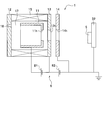
- FIG. 2 is a schematic diagram showing the configuration of the ion gun 1 and parts related to the ion gun 1 of the ion milling apparatus 100 in the present embodiment.
- the ion gun 1 includes an anode 11, a pair of cathodes 12 and 13 arranged so as to sandwich the anode 11, an acceleration electrode 14, a magnet 15, and a gas inlet 16.
- the anode 11 includes a cylindrical portion and a bottom portion, and is formed in a cylindrical shape extending in the ion beam emission direction.
- the anode 11 is made of, for example, a nonmagnetic conductor such as aluminum.
- the anode 11 is fitted inside an insulator (not shown).
- the outer peripheral surface of the cylindrical portion is in contact with the inner peripheral surface of the insulator, and the inner peripheral surface of the cylindrical portion faces the inside of the ionization chamber 17.
- the bottom is formed on the side opposite to the cathode 12, and an opening 11h (anode hole) is provided in the center of the bottom.
- an opening 11h anode hole
- the anode 11 is electrically insulated from the cathode 12, the cathode 13, and the magnet 15 by an insulator (not shown).
- the cathode 13 disposed on the same side as the acceleration electrode 14 is made of a magnetic conductor such as pure iron, for example.
- the cathode 13 is provided with an opening 13h in the center.
- the opening 13h allows ions to pass through, and an appropriate gas partial pressure between the space in the ionization chamber 17 of the ion gun 1 to which a predetermined gas is supplied from a gas introduction port 16 to be described later and the space in the sample chamber 5. It is formed in the size necessary to keep
- the cathode 13 disposed on the same side as the acceleration electrode 14 functions as an electrode for generating ions while maintaining an appropriate gas partial pressure between the atmosphere on the anode 11 side and the atmosphere on the acceleration electrode 14 side. .
- the cathode 12 disposed on the opposite side of the acceleration electrode 14 across the anode 11 is made of a magnetic conductor such as pure iron, for example.
- the cathode 12 may be provided with, for example, a gas introduction port 16 through which a discharge gas G supplied from a gas cylinder or the like described later flows.
- the acceleration electrode 14 is provided on the opposite side to the inside of the ionization chamber 17 with the opening 13h of the cathode 13 interposed therebetween.
- the acceleration electrode 14 is formed on the side opposite to the cathode 13.
- the acceleration electrode 14 is made of a nonmagnetic material having conductivity, such as stainless steel.
- An opening 14 h is provided at the center of the acceleration electrode 14.
- the acceleration electrode 14 is kept at the ground potential.
- the acceleration electrode 14 may be formed in a cylindrical shape or a cylindrical shape.
- the magnet 15 is made of a ferromagnetic material having conductivity including a ferromagnetic metal, such as a neodymium magnet, and is formed in a cylindrical shape extending in the ion beam emission direction.
- the cathode 12 is attracted to one end of the magnet 15 by, for example, a magnetic force.
- One end of the magnet 15 is connected to the cathode 12.
- the cathode 13 is attracted to the other end of the magnet 15 by, for example, a magnetic force.
- the cathode 13 is connected to the other end of the magnet 15. Since the cathode 12, the cathode 13 and the magnet 15 are electrically connected to each other, the cathode 12, the cathode 13 and the magnet 15 are kept at the same potential.
- the ionization chamber 17 is partitioned by the magnet 15, the cathode 12 and the cathode 13, and the opening 13h is also a hole formed in the ionization chamber 17. At this time, the magnet 15 generates a magnetic field inside the ionization chamber 17. Further, since the cathode 12 and the cathode 13 form a magnetic path, the magnetic field generated in the ionization chamber 17 can be strengthened by the cathode 12 and the cathode 13.
- the shape of the magnet 15 is not limited to a cylindrical shape. Therefore, the magnet 15 may be formed in a cylindrical shape.
- the insulator (not shown) is formed in a cylindrical shape extending in the ion beam emission direction.
- the insulator is disposed inside the magnet 15, and the outer peripheral surface of the insulator is in contact with the inner peripheral surface of the magnet 15.
- the insulator is made of, for example, a nonmagnetic material having electrical insulation properties such as ceramics.
- the Penning ion gun used in the present embodiment is a three-electrode system, so that the energy of ions hitting the opening 13h (cathode hole) and the opening 14h (ion beam passage hole) can be suppressed. For this reason, the Penning ion gun can reduce the deformation and contamination of the opening 13h of the cathode 13 and the opening 14h of the acceleration electrode 14 and obtain a stable ion current.
- the cathode 13 disposed on the same side as the acceleration electrode 14 has a role as an orifice for maintaining an appropriate gas partial pressure in the ion gun 1. That is, if the opening 13h is consumed and deformed (mainly enlarged), the appropriate gas partial pressure cannot be maintained and the discharge becomes unstable. For this reason, periodic replacement of the cathode and adjustment at each use of the gas flow rate are preferable.
- the electrode member such as the cathode is preferably a material having both conductivity and ion resistance.
- the electrode member such as the cathode is preferably formed of a hard metal material such as titanium, molybdenum, or tungsten.
- the gas introduction port 16 is a supply port for supplying a discharge gas to be ionized in the ion gun 1 into the ion gun 1.
- the gas inlet 16 is provided, for example, in the cathode 12 disposed on the side opposite to the acceleration electrode 14.
- a discharge gas having a low flow rate that does not affect the start of discharge between the electrodes from the gas inlet 16 is introduced into the ionization chamber 17 of the ion gun 1.
- Examples of the discharge gas (ionized gas) introduced into the ion gun 1 include rare gases such as argon, helium, and xenon.
- One terminal of the discharge power supply 81 is electrically connected to the cathode 12 and the cathode 13.
- the other terminal of the discharge power supply 81 is electrically connected to the anode 11.
- a discharge voltage is applied by the discharge power supply 81 between the cathode 12 and the cathode 13 and the anode 11.
- One terminal of the acceleration power source 82 is electrically connected to the cathode 12 and the cathode 13.
- the other terminal of the acceleration power source 82 is electrically connected to the acceleration electrode 14.
- An acceleration voltage is applied by the acceleration power source 82 between the cathode 12 and the cathode 13 and the acceleration electrode 14.
- FIG. 3 is a schematic view showing a state in which the ion beam B is emitted from the ion gun 1 of the ion milling apparatus 100 according to the present embodiment.
- a discharge gas G is introduced through a gas inlet 16 into a space surrounded by the anode 11 in the ionization chamber 17 of the ion gun 1.
- a voltage of about several kV is applied between the anode 11 and the cathodes 12 and 13 by the discharge power supply 81 while maintaining an appropriate gas partial pressure.
- a positive voltage is applied to the anode 11 with respect to the cathode 12 and the cathode 13.
- the cathodes 12 and 13 are applied with a negative voltage with respect to the anode 11 and emit electrons from the surface.
- the magnet 15 exists around the ionization chamber 17 and a magnetic field is formed in the ionization chamber 17. Further, cathodes 12 and 13 exist on both sides of the anode 11. For this reason, the emitted electrons are swung by the orbit being bent by the magnetic field formed in the ionization chamber 17.
- the collided discharge gas G is ionized.
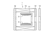
- FIG. 4A is a schematic diagram showing a state in which the deposit D adheres to the surface of the anode 11 of the ion milling apparatus 100 in the present embodiment.
- FIG. 4B is a schematic diagram illustrating a state in which the deposit D attached to the surface of the anode 11 of the ion milling apparatus 100 according to the present embodiment short-circuits the anode 11 and the cathode 12.
- the direct current discharge type plasma discharge ion gun irradiates the ion beam to the ion gun components such as the acceleration electrode 14 and the sample stage.
- the ion gun components such as the acceleration electrode 14 and the sample stage.
- the cathode 13 is irradiated with the ion beam B.
- sputtered particles are also emitted from the component parts of the ion gun 1 and adhere to other component parts (redeposition) in the sample chamber 5 or inside the ion gun 1 (see FIG. 4A).
- the sputtered particles adhering to the anode 11 due to redeposition accumulate in layers with the processing (discharge) time, and peel off in a needle shape when reaching a certain thickness.
- the Penning discharge type ion gun 1 has a structure in which the cathodes 12 and 13 sandwich the anode 11 from both sides, and a voltage is applied between the anode 11 and the cathodes 12 and 13. And since the peeled substance De has electroconductivity, it may contact and short-circuit the anode 11 and the cathodes 12 and 13 (refer FIG. 4B). Therefore, the ion milling apparatus 100 requires periodic cleaning and maintenance of the ion gun 1 (anode 11).
- the anode maintenance cycle is often about 100 hours, depending on the cathode material and usage conditions. Assuming that one use time is 8 hours and twice a day, the ion gun will be serviced every week.
- the redeposition that occurs in the ion gun 1 may cause a short circuit between the electrodes, but the conductivity of the electrodes may also decrease. Since the deposit D derived from the cathode made of a metal such as titanium or molybdenum is easily oxidized, the oxidation of the deposit D deposited on the anode 11 causes the conductivity of the anode 11 to decrease. When the conductivity of the anode 11 is lowered, the anode 11 is charged and discharge becomes unstable.
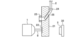
- FIG. 5A is a schematic diagram showing a beam current detection plate 21 provided with a nozzle insertion mechanism in the present embodiment.
- FIG. 5B is a schematic diagram showing beam current detection by the beam current detection plate 21 provided with the nozzle insertion mechanism in the present embodiment.
- FIG. 5C is a schematic diagram showing a state where the gas injection nozzle 2 in this embodiment is inserted into the ion gun 1.
- a beam current detection plate 21 for blocking the ion beam B and measuring the current of the ion beam B is opposed to the opening of the ion gun 1 in front of the ion gun 1. Be placed.
- the beam current detection plate 21 in this embodiment includes a beam current detection region 22, a beam current blocking region 26, and a gas nozzle port 23 in this order on the opposite surface of the ion gun 1, and the sample S side ( The nozzle insertion port 25 and the nozzle fixing jig 24 are provided on the opposite side.
- the beam current detection plate 21 has a structure in which the gas nozzle port 23 and the nozzle insertion port 25 communicate with each other and the gas injection nozzle 2 can pass through the beam current detection plate 21. ing.
- the path from the nozzle insertion port 25 to the gas nozzle port 23 has a circular cross section and is arranged in an arc shape in cross section toward the opening of the ion gun 1 to prevent the gas injection nozzle 2 from being blocked due to crushing or the like. .
- the gas injection nozzle 2 may be connected to an injection gas supply mechanism including a gas supply valve capable of adjusting the pressure, injection amount, injection time, and the like of the injection gas, and a gas holder that temporarily stores the injection gas (illustrated). (Omitted).
- the injection gas is supplied from a gas supply source such as a gas cylinder to the injection gas supply mechanism.
- the gas injection nozzle 2 is inserted and fixed in the nozzle fixing jig 24 on the back surface of the beam current detection plate 21, and is inserted into the nozzle insertion port 25 from the back surface.
- the inserted gas injection nozzle 2 is supported by a path from the nozzle insertion port 25 to the gas nozzle port 23.
- the gas injection nozzle 2 is supported by the gas nozzle port 23 and jumps out of the gas nozzle port 23 (see FIG. 5C).
- the gas injection nozzle 2 is preferably formed of a material that is deformed by an external stress having appropriate elasticity that can be inserted from the nozzle insertion port 25 to the gas nozzle port 23. Further, the gas injection nozzle 2 may be formed of a material that is not easily deformed by its own weight or injection of the injection gas. Examples of the material forming the gas injection nozzle 2 include a polyethylene resin, a polypropylene resin, and a fluorine resin.
- the shape of the gas injection port at the tip of the gas injection nozzle 2 may be any shape.
- the shape of the gas injection port at the tip of the gas injection nozzle 2 is, for example, an ellipse, a wide range of deposits D can be processed at a time.
- the shape of the gas injection port a small-diameter circle, for example, the pressure of the injection gas is increased and the treatment of the deposit D is ensured.
- the outer diameter of the gas injection nozzle 2 may be appropriately configured to be an outer diameter that can be inserted into the ion gun 1 through the opening of the ion gun 1. What is necessary is just to comprise the internal diameter of the gas injection nozzle 2 suitably in the internal diameter which can inject injection gas into the opening part of the ion gun 1, and the inside of the ion gun 1.
- FIG. The length of the gas injection nozzle 2 may be appropriately configured so as to be inserted into the ion gun 1 through the opening of the ion gun 1.
- the beam current detection plate 21 includes, for example, a support portion that is threaded at the top, and is configured to be movable (movable up and down) at least on one axis in the vertical direction by rotation of a gear that meshes with the screw. (Not shown).
- the gas injection nozzle 2 has a threaded portion, and is configured to be movable (movable up and down) at least on one axis in the vertical direction by rotation of a gear meshing with the threaded portion.
- These screw portions may be configured, for example, by inserting a cylindrical separate member (gear) having a thread on the outer periphery through the gas injection nozzle 2.
- the gear that drives the beam current detection plate 21 and the gear that drives the gas injection nozzle 2 may be the same, and the beam current detection plate 21 and the gas injection nozzle 2 may be driven by one gear.
- the number of threads of the beam current detection plate 21 with respect to the number of threads of the gear and the number of threads of the gas injection nozzle 2 with respect to the number of threads of the gear are changed. (By changing the gear ratio), the movement amount of the beam current detection plate 21 and the movement amount of the gas injection nozzle 2 can be changed. That is, the number of threads of the beam current detection plate 21 is made larger than the number of threads of the gas injection nozzle 2, and the amount of movement of the gas injection nozzle 2 is larger than the amount of movement of the beam current detection plate when one gear rotates. Can be increased.
- the gas injection nozzle 2 protrudes or retracts from the gas nozzle port 23.
- the gas injection nozzle 2 may be configured to be inserted into the inside through the opening of the ion gun 1.
- the injection gas injected to process (remove and move) the deposit D remains in the sample chamber 5 or the ion gun 1, it is a gas that does not easily affect the injection or processing of the ion beam B. preferable.
- the injection gas is more preferably the same type of gas as the discharge gas G in the ion gun 1.
- the sample holding member installation unit 41 in the present embodiment is configured to include, for example, an X direction moving stage, a Y direction moving stage, and a Z direction moving stage.
- sample holding member installation portion 41 in the present embodiment is a stage capable of three-dimensional movement in the XYZ directions, rotation around an axis perpendicular to the XY plane, and tilting which can be known and controlled by five axes. Also good.
- the sample holding system 3 is a sample rotation stage that rotates the installed sample holding member 31 and an angle adjustment that can arbitrarily adjust the inclination angle of the rotation center axis of the sample rotation stage with respect to the center line of the ion beam B. It may be configured to include a mechanism and a sample position adjusting mechanism that can eccentrically adjust the positional relationship between the rotation axis of the sample rotating stage and the center line of the ion beam B.
- the sample rotation stage includes, for example, a gear mechanism, and is driven by the sample holding member driving unit 44 so that the installed sample holding member 31 rotates.
- control system 6 in this embodiment will be described in detail.
- the control system 6 includes the control unit 61, the operation unit 62, and the display unit 63.
- the control unit 61 includes an arithmetic processing unit, a storage unit, an input unit, and an output unit.
- the arithmetic processing unit includes a CPU (Central Processing Unit).
- the arithmetic processing unit reads a program stored in the storage unit and performs a calculation necessary for controlling the ion milling apparatus 100.
- the arithmetic processing unit is connected to an input unit, an output unit, and the like, receives various information signals, and transmits a calculation result as a signal necessary for controlling the ion milling apparatus 100.
- the storage unit includes storage media such as ROM (Read Only Memory) and RAM (Random Access Memory).
- the storage unit includes an ion milling automation program, deposit processing (short circuit elimination, discharge stabilization, etc.) automation program, ion gun 1 control program, evacuation system 7 control program, power supply system 8 control program, and the like. Stored. Further, data on various states during processing of the apparatus, such as an applied voltage between the anode and the cathode and between the cathode accelerating electrodes, a beam current value, and the like may be stored. Processing conditions for ion milling set by the user, conditions for ion milling performed previously, and the like may be stored.
- the arithmetic processing unit and the storage unit constituting the control unit 61 may be configured as a microcomputer having these functions (hereinafter, referred to as a microcomputer as appropriate). Moreover, the arithmetic processing part and the memory
- the input unit includes detection measuring means such as a sensor for measuring the current flowing through the cathode, an applied voltage between the anode and the cathode, a sensor for measuring the applied voltage between the cathode acceleration electrodes, and a sensor for measuring the current value of the beam current. Is done.
- detection measuring means such as a sensor for measuring the current flowing through the cathode, an applied voltage between the anode and the cathode, a sensor for measuring the applied voltage between the cathode acceleration electrodes, and a sensor for measuring the current value of the beam current. Is done.
- a receiving unit that receives an operation instruction in the operation unit 62 may be included.
- the output unit includes means for creating a sound for notifying the end of processing, an alarm sound for notifying abnormality during automatic control, a calculation result of the arithmetic processing unit, and display data for notifying a control mode of automatic control.
- the input window can be selected by a select key (Select) and numerical values can be input by using the “Up” and “Down” buttons. Allows selection. Furthermore, the selected numerical value is registered by the enter key (Enter).
- the operation unit 62 (operation panel) is provided with a gas injection condition setting unit (not shown) that sets conditions for maintenance of the ion gun 1 by gas injection of the injection gas from the gas injection nozzle 2.
- a gas injection nozzle 2 that injects an injection gas into the ion gun 1 is inserted, and an injection gas is injected between the anode 11 and the cathode 12 to cause a short circuit or unstable discharge. It is characterized by processing (blowing off) the deposit D which is a factor.
- the operation signal (selection information) in the operation unit 62 is transmitted to the arithmetic processing unit via the input unit constituting the control system 6.
- the calculation processing unit performs calculation based on the read program for the transmitted input signal, and transmits the calculation result to the sample holding member driving unit 44 and the output unit. Based on the received control signal, the sample holding member driving unit 44 drives the condition selected by the operation unit 62.
- FIG. 6 is a flowchart showing an operation procedure before starting machining in the present embodiment.
- the sample S to be processed is placed in the sample chamber 5 by the user of the ion milling method. After the arrangement of the sample S is completed, the user presses the evacuation start button arranged on the operation unit 62 (exhaust start).
- a signal for pressing the evacuation start button is transmitted to the arithmetic processing unit via the input unit of the control unit 61.
- the arithmetic processing unit that has received the signal to press the evacuation start button reads the maintenance program for the ion gun 1 before processing performed by injecting the injection gas from the storage unit, or based on the maintenance program that has been read in advance. Perform maintenance. Specifically, it is as follows.
- the controller 61 confirms that all the vacuum pumps of the evacuation system 7 (see FIG. 1) are stopped (S1). When all the vacuum pumps are not stopped, the control unit 61 stops all the vacuum pumps. This operation prevents the vacuuming system 7 from being damaged due to the inside of the sample chamber 5 being opened to the atmosphere while the vacuuming system 7 (see FIG. 1) is operating.
- the control unit 61 may transmit a signal indicating that the inside of the ion gun 1 is being maintained to the output unit and notify the user by displaying the output unit or the like.
- control unit 61 confirms that the inside of the sample chamber 5 is open to the atmosphere by a pressure sensor constituting the input unit (S2).
- the control unit 61 transmits a signal to the vacuum system 7, for example, stops the pump and opens the inside of the sample chamber 5 to the atmosphere.
- the control unit 61 moves the beam current detection plate 21 including the gas injection nozzle 2 through the output unit so that the gas injection nozzle 2 (the opening thereof) faces the opening (emission port) of the ion gun 1 (S3).
- the control unit 61 may feed the gas injection nozzle 2 close to the opening of the ion gun 1 in accordance with the movement of the beam current detection plate 21.
- the control unit 61 injects the injection gas from the gas injection nozzle 2 toward the inside (opening) of the ion gun 1 with the gas injection nozzle 2 facing the opening of the ion gun 1 (S4).
- the injection pressure of the injection gas is preferably 0.01 MPa or more.
- the total injection time of the injection gas is preferably 1 second or more. Even when the injection range of the injection gas is expanded by moving the beam current detection plate 21 provided with the gas injection nozzle 2 while maintaining the state where the gas injection nozzle 2 faces the opening of the ion gun 1 during the injection of the injection gas. Good.
- the injection pressure of the injection gas may be changed during the injection of the injection gas.
- the injection of the injection gas may be intermittent. Since the inside of the sample chamber 5 and the inside of the ion gun 1 are open to the atmosphere, it is preferable that the injection pressure of the injection gas is high in consideration of the deceleration of the injection gas.
- the ejected gas blows away deposits D, dust and the like adhering to the acceleration electrode 14 arranged around the opening of the ion gun 1.
- a sample processing interruption cause such as a short circuit between the acceleration electrode 14 and the cathode 13 due to the deposit D during the sample processing and a short circuit between the anode 11 and the cathodes 12 and 13. Become.
- the control unit 61 continuously sends out the gas injection nozzle 2 and inserts the gas injection nozzle 2 into the opening (injection port) of the ion gun 1 (see FIG. 5C) (S5).
- the controller 61 injects the injection gas from the gas injection nozzle 2 toward the inside of the ion gun 1 with the gas injection nozzle 2 inserted into the opening of the ion gun 1 (S6).
- the injection pressure of the injection gas is preferably 0.01 MPa or more.
- the total injection time of the injection gas is preferably 1 second or more.
- the gas injection nozzle 2 may be moved to widen the injection range of the injection gas.
- the injection pressure of the injection gas may be changed during the injection of the injection gas.
- the injection of the injection gas may be intermittent.
- the injected jet gas blows away deposits D, dust and other deposits attached to the acceleration electrode 14 arranged around the injection port of the ion gun 1. Further, the injected jet gas blows away deposits D, dust, and the like attached to the anode 11, the cathodes 12, 13, etc. disposed inside the ion gun 1.
- a sample processing interruption cause such as a short circuit between the anode 11 and the cathodes 12 and 13 and a short circuit between the acceleration electrode 14 and the cathode 13 due to the deposit D during the sample processing. Become. Furthermore, it is possible to reduce the number of times of maintenance accompanying the decomposition of the ion gun 1.
- the maintenance (S3 to S6) of the ion gun 1 prior to processing performed by injecting the injection gas J is performed for the purpose of preventing the occurrence of the sample processing interruption, and therefore, it may be performed for a total of 15 seconds or less at the same location. preferable. As a result, it is possible to prevent the injection gas from being injected more than necessary, improve the processing efficiency, and save the injection gas.
- the control unit 61 moves the gas injection nozzle 2 (ion current detection plate 21) to a position that does not hinder the irradiation of the ion beam B (S7). ). At the same time, the control unit 61 moves the shutter position of the ion current detection plate 21 so as to face the ion gun 1.
- control unit 61 transmits a signal to the vacuuming system 7 to close the atmosphere release valve, and prepares for vacuuming by the vacuuming system 7.
- the control unit 61 transmits a signal to the evacuation system 7 and evacuates the sample chamber 5 and the ion gun 1 to a pressure at which the ion beam B can be emitted by the pump of the evacuation system 7 (S8).
- the pump for high vacuuming may be operated after the state in the sample chamber 5 is stabilized.
- the control unit 61 confirms that the inside of the sample chamber 5 is evacuated by a pressure sensor that constitutes the input unit.
- the control unit 61 may transmit a display for informing that the evacuation in the sample chamber 5 is completed or a signal for generating a sound to the output unit, and notify the user by a display on the output unit. At the same time, the control unit 61 may notify the user that an operation such as input of machining conditions is possible and prompt the operation.
- the control unit 61 waits for an operation by the user such as input of processing conditions and pressing of a processing start button (standby).
- control unit 61 when controlling from the sample installation in the sample chamber to the release of the sample chamber to the atmosphere after the completion of processing based on the control program, the control unit 61 confirms that the evacuation in the sample chamber 5 has been completed and the processing conditions are satisfied. Processing of the sample S may be continued without notifying that the input is possible.
- the deposit D due to redeposition accumulates inside the ion gun 1, and the deposit D also adheres to the acceleration electrode 14 and the cathode 13 around the opening of the ion beam B. I will do it.
- detection of the deposit D during sample processing and processing of the deposit D will be described.
- the controller 61 constantly checks the state of the ion gun 1 during discharge and the state of the ion gun 1 during sample processing. When the short circuit between the electrodes or the instability of the discharge of the ion gun 1 is detected, the control unit 61 temporarily stops the processing of the sample S and injects the injection gas toward the ion gun 1.
- Detecting the short circuit between the electrodes and the unstable discharge of the ion gun 1 is performed, for example, as follows (determination criteria for short circuit between the electrodes and unstable discharge).
- the control unit 61 monitors the current of the beam B in the beam current detection region 22 of the beam current detection plate 21 connected to the input unit. If the current flowing through the detector in the beam current detection region 22 is equal to or lower than the detection limit of the beam B despite the discharge voltage being applied to the ion gun 1, the control unit 61 determines that the discharge of the ion gun 1 has stopped. It is determined that a short circuit has occurred between the electrodes.
- the control unit 61 When the current flowing through the cathode 12 and the discharge power supply 81 is detected by the sensor constituting the input unit and the current value becomes larger than a predetermined current value, the control unit 61 causes a short circuit between the anode 11 and the cathode 12. It may be determined that it has occurred. When the current flowing between the anode 11 and the discharge power supply 81 is measured and the current becomes larger than a predetermined value, the control unit 61 may determine that a short circuit has occurred between the anode 11 and the cathode 12. .
- control unit 61 monitors the current of the beam B in the beam current detection region 22 of the beam current detection plate 21 connected to the input unit.
- a predetermined time for example, 5 minutes
- a predetermined value for example, 5% or more
- the control unit 61 discharges the ion gun 1. May be determined to be unstable.
- the control unit 61 discharges the ion gun 1. May be determined to be unstable.
- the current flowing through the acceleration electrode 14 and the acceleration power source 82 is measured and the current becomes larger than a predetermined value, it may be determined that a short circuit has occurred between the cathode 13 and the acceleration electrode 14.
- the current flowing through the acceleration electrode 14 and the acceleration power source 82 is measured and the current fluctuation in a predetermined time (for example, 5 minutes) becomes large (for example, 5% or more), the discharge of the ion gun 1 is unstable. You may judge. The state of the ion gun 1 may be confirmed at an appropriate time interval such as every 1 minute or every 3 minutes in parallel with the processing of the sample S.
- control unit 61 When the control unit 61 detects a short circuit between the electrodes or an unstable discharge of the ion gun 1, the control unit 61 is ready to inject the injection gas.
- FIG. 7 is a flowchart showing an operation procedure for processing (removing) the deposit D of the ion milling apparatus 100 during sample processing in the present embodiment.
- the control unit 61 stops the high vacuum pump such as a turbo molecular pump that constitutes the vacuum system 7 (S11). ) Confirm that the pump for high vacuuming has stopped. By this operation, failure of the high vacuum pump of the vacuum system 7 due to a sudden change in the degree of vacuum in the sample chamber 5 due to the injection of the injection gas is avoided.
- the high vacuum pump such as a turbo molecular pump that constitutes the vacuum system 7 (S11).
- the exhaust of the sample chamber 5 by the roughing pump such as a rotary pump constituting the evacuation system 7 is continued.
- the inside of the sample chamber 5 and the ion gun 1 can be kept in a vacuum state or a reduced pressure state lower than the atmospheric pressure.
- the discharge gas supplied from the gas supply port of the ion gun 1 is extremely small, it does not affect the injection of the injection gas from the gas injection nozzle 2. Therefore, the supply of the discharge gas may be continued or stopped before the injection gas is injected.
- control unit 61 moves the beam current detection plate 21 downward while keeping the inside of the sample chamber 5 and the ion gun 1 in a vacuum state or a reduced pressure state lower than the atmospheric pressure, thereby opening the ion gun 1.
- the outlet) and the gas nozzle port 23 face each other (S12).
- the control unit 61 extends the gas injection nozzle 2 toward the opening of the ion gun 1 (S13).
- the movement of the beam current detection plate 21 (S12) and the feeding of the gas injection nozzle 2 (S13) may be performed simultaneously.
- the control unit 61 supplies the injection gas from the injection gas supply mechanism to the gas injection nozzle 2 and injects the injection gas from the gas injection nozzle 2 toward the acceleration electrode 14 and the cathode 13 (S14).
- the deposit D adherered matter
- the ion gun 1 cathode 13
- the injection of the injection gas may be performed not only once but a plurality of times.
- the deposit D may move only a little. That is, the contact (short circuit) between the anode 11 and the cathode 12 due to the deposit D, the contact (short circuit) between the acceleration electrode 14 and the cathode 13 may be eliminated.
- the discharge of the deposit D from the ion gun 1 will be described in a fourth embodiment to be described later.
- the inside of the sample chamber 5 and the inside of the ion gun 1 are in a vacuum state or a reduced pressure state lower than the atmospheric pressure, the injected injection gas is difficult to decelerate. Therefore, even if the injection pressure of the injection gas is smaller than the injection pressure of the injection gas before the sample processing (S4), the same effect as before the sample processing can be obtained. By reducing the injection pressure of the injection gas, it is possible to save the injection gas.
- control unit 61 When the deposit D is adhered between the anode 11 and the cathode 12, the control unit 61 further extends the gas injection nozzle 2 and inserts it into the inside from the openings (opening 14h, opening 13h) of the ion gun 1 (see FIG. 5B). (S15). The movement of the beam current detection plate 21 and the feeding of the gas injection nozzle 2 may be performed simultaneously.
- the control unit 61 supplies the injection gas from the injection gas supply mechanism to the gas injection nozzle 2 and injects the injection gas from the gas injection nozzle 2 toward the anode 11 and the cathodes 12 and 13 (S16).
- the deposit D adherered matter
- the injection of the injection gas may be performed not only once but a plurality of times.
- control unit 61 moves the gas jet nozzle 2 to a position that does not hinder the irradiation of the ion beam B (S17).
- the controller 61 moves the ion gun 1 so as to face the beam current detection region 22.
- the control unit 61 again activates the high vacuum pump (S18). Thereby, the control unit 61 reduces the pressure in the sample chamber 5 and the ion gun 1 to a pressure at which the ion beam B can be emitted.
- the operation of the pump for high vacuum again may be performed after the gas state in the sample chamber 5 is stabilized.
- the control unit 61 resumes the processing of the sample S that has been temporarily suspended.
- the control unit 61 applies a discharge voltage to the ion gun 1 so that there is no short circuit between the electrodes and no unstable discharge of the ion gun 1 (does not correspond to the criteria for determining the short circuit between the electrodes or the unstable discharge). After confirmation, the processing of the temporarily suspended sample S may be resumed.
- the control unit 61 When processing (removal) of the deposit D by injection of the injection gas is insufficient, the control unit 61 performs a short circuit between the electrodes or the ion gun 1 during re-application of the discharge voltage to the ion gun 1 or after resuming the sample processing. It will be detected again as an unstable discharge. Therefore, when the controller 61 detects again the short circuit between the electrodes or the instability of the discharge of the ion gun 1, the control unit 61 may inject the injection gas again and try to process (remove) the deposit D.
- the control unit 61 (arithmetic processing unit) May display on the display unit 63 that the ion gun 1 is recommended for maintenance because of the short circuit between the anode 11 and the cathodes 12 and 13 caused by the deposit D, or the unstable discharge. Further, the control unit 61 may interrupt the processing of the sample S and display the fact on the display unit 63 for safety in order to prevent the processing of the sample S from failing.
- the ion milling apparatus 100 has a configuration in which the gas injection nozzle 2 is disposed in the sample chamber 5, so that the deposit D is injected by injecting an injection gas while keeping the inside of the sample chamber 5 in a vacuum. Can be processed (removed).
- the ion milling method in the present embodiment makes it possible to return from the short-circuit state without opening the sample chamber 5 to the atmosphere even when a short circuit occurs during sample processing. Even when the discharge becomes unstable during sample processing, the discharge can be stabilized without opening the sample chamber 5 to the atmosphere.
- the ion gun when an ion gun electrode short-circuit occurs during ion milling, the ion gun is disassembled to treat (remove) deposits on the anode surface or deposits that short-circuit the anode and cathode. Needed to be maintained. In addition, it is necessary to stop the ion milling process and wait until the temperature of the electrode component of the ion gun, which has increased in temperature due to application of a high voltage, is lowered to a level where it can be touched by hand. And in order to decompose
- Cross-sectional ion milling may be performed while indirectly cooling the sample using liquid nitrogen or the like. If the sample chamber is opened to the atmosphere while the ion milling apparatus is cooled, frost adheres to the apparatus. Due to frost adhesion, the performance of the apparatus deteriorates. For this reason, in the case of short-circuiting during cooling processing, in addition to the operation when the sample is not cooled, in order to avoid frost adhesion to the sample when the sample chamber is open to the atmosphere, cooling is stopped and the temperature of the sample is The apparatus was returned to room temperature by waiting for a long time in a state where the vacuum was maintained until it rose to room temperature. After that, the apparatus was opened to the atmosphere, and the deposit D or the like was processed (removed) to eliminate problems such as a short circuit.
- the sample chamber 5 is provided with the gas injection nozzle 2 supported by the beam current detection plate 21. Thereby, it is possible to inject the injection gas while keeping the inside of the sample chamber 5 at a vacuum level capable of preventing frost adhesion without opening the sample chamber 5 to the atmosphere.
- the deposit (D) can be treated (removed) without opening the sample chamber 5 to the atmosphere while preventing frost from adhering, and the short circuit can be eliminated and the discharge can be stabilized.
- the deposit D is processed (removed) by injecting the injection gas from the gas injection nozzle 2, it is possible to recover from the short-circuit state or the like without disassembling the ion gun 1. Further, since the deposit D is processed (removed) by injecting the injection gas, it is possible to return from the short-circuit state or the like without waiting for the temperature drop of the components of the ion gun 1 that has risen with the processing.
- the injection gas can be injected while maintaining the position of the sample stage 32, the reproducibility of the irradiation position (processing position) of the ion beam B even if the processing is continued after the short-circuit state is resolved. Is high and inconvenient.
- the so-called inert gas argon or the like
- the sample S to be processed does not react with the jet gas used for the treatment of the deposit D or the like.
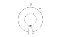
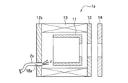
- FIG. 8A is a schematic diagram showing the cathode 12a of the ion gun 1a in which the gas injection nozzle insertion port 18a in the present embodiment is provided in the cathode 12a.
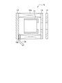
- FIG. 8B is a schematic cross-sectional view of the ion gun 1a in which the gas injection nozzle insertion port 18a in the present embodiment is provided in the cathode 12a.
- the position where the insertion port 18a of the gas injection nozzle 2a is provided is preferably a position that does not affect the ionization (plasmaization) of the gas, and is preferably a place other than the discharge region 20. (See FIG. 8A) It is sufficient to provide at least one insertion port 17.
- the insertion port 18a of the gas injection nozzle 2 in the cathode 12a located on the opposite side to the opening of the ion gun 1 it becomes easy to inject the injection gas J in the vicinity of the anode 11 and the cathode 12a, and the injection pressure of the injection gas J Can be lowered (see FIG. 8B).
- the usage amount of the injection gas J such as argon can be reduced.
- Deposits (not shown) that short-circuit the anode 11 and the cathode 12a are easily treated (removed) by gas injection by the gas injection nozzle 2a.
- the deposit (not shown) deposited on the surface of the anode 11 is treated (removed) so as to peel from the surface of the anode 11. It becomes possible.
- the material for forming the gas injection nozzle 2a there is no limitation on the material for forming the gas injection nozzle 2a.
- the gas injection nozzle 2a is formed of a material that is not easily deformed by external stress, moderate weight, injection of the injection gas J, or the like having appropriate elasticity that can be inserted into the ion gun 1a from the insertion port 18a.
- the material for forming the gas injection nozzle 2a include polyethylene resin, polypropylene resin, and fluorine resin.
- the shape of the gas injection nozzle 2a may be any shape.
- the gas injection port of the gas injection nozzle 2a on the side surface of the nozzle tip portion with the nozzle tip closed, it becomes possible to directly inject the gas to the deposit that short-circuits the anode 11 and the cathodes 12 and 13. .
- the gas injection nozzle insertion mechanism (not shown) can have an arbitrary structure, for example, a mechanism using gears as in the first embodiment.
- FIG. 9 is a schematic cross-sectional view of the ion gun 1b in which the gas injection nozzle insertion port 18b in the present embodiment is provided in the magnet 15b.
- the position where the insertion port 18b of the gas injection nozzle 2b is provided is preferably a position that does not affect the magnetic field formed by the magnet 15b. At least one insertion port 18b may be provided, and a plurality of insertion ports 18b may be provided in order to suppress the influence on the magnetic field. When a plurality of insertion openings are provided, it is preferable that the insertion opening 18b is provided symmetrically with respect to the central axis (ion beam axis) of the magnet 15b in order to suppress the influence on the magnetic field.
- the insertion port 18b between the anode 11 and the cathode 12 it becomes easy to inject the injection gas in the vicinity of the anode 11 and the cathode 12, and the injection pressure of the injection gas can be lowered.
- the injection pressure of the injection gas By reducing the injection pressure of the injection gas, the amount of injection gas such as argon can be reduced. Deposits (not shown) that short-circuit the anode 11 and the cathode 12 are easily treated (removed) by gas injection by the gas injection nozzle 2b.
- the injection gas can be injected while holding the position of the sample holding system 3 (see FIG. 1), and the processing accuracy of the sample S can be maintained.
- the gas injection nozzle 2b is preferably formed of a material that is difficult to be deformed by external stress, moderate weight, injection of injection gas, or the like having appropriate elasticity that can be inserted into the ion gun 1b from the insertion port 18b.
- the material for forming the gas injection nozzle 2b include a polyethylene resin, a polypropylene resin, and a fluorine resin.
- the shape of the gas injection nozzle 2b may be any shape.
- the gas injection port of the gas injection nozzle 2b is treated (removed) so that deposits (not shown) deposited on the surface of the anode 11 are peeled off from the surface of the anode 12 by providing the gas injection port on the side surface of the nozzle tip with the nozzle tip closed, for example. ). Further, since the nozzle tip is closed, the deposit (not shown) that short-circuits the anode and the cathode at the nozzle tip can be directly moved.
- the insertion mechanism (not shown) of the gas injection nozzle 2b can have an arbitrary structure, for example, a mechanism using gears as in the first embodiment.
- FIG. 10A is a schematic diagram showing an ion gun 1c in which a discharge port is provided in the magnet 15c in the present embodiment.
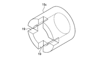
- FIG. 10B is a schematic diagram showing a magnet 15c of the ion gun 1c in the present embodiment.
- the deposit D removed from the surface of the anode 11 by the injection gas J can be discharged from the ion gun 1c.
- an ion milling apparatus can be used for a long time, without decomposing
- the position where the discharge port 19 is provided is preferably a position where there is no influence on gas ionization (plasmaization).
- a plurality of discharge ports 19 may be provided in order to suppress the influence on the magnetic field.
- the discharge port 19 is preferably provided symmetrically with respect to the central axis (ion beam axis) of the magnet 15c in order to suppress the influence on the magnetic field (see FIG. 10B).
- the discharge port 19 When the discharge port 19 is provided between the cathode 12 and the anode 11 located on the opposite side of the opening of the ion gun 1c, the deposit D which has short-circuited the anode 11 and the cathode 12 by injecting a spray gas from the opening of the ion gun 1c. It becomes easy to discharge. Further, by providing the discharge port 19 between the cathode 13 and the anode 11 located on the opening side of the ion gun 1c, the deposit D attached to the acceleration electrode 14 can be easily discharged. At least one discharge port 19 may be provided.
- the inside of the ion gun 1b and the inside of the sample chamber 17 can be kept in a vacuum state except when the deposit D is discharged.
- the deposit D may be sucked and discharged from the discharge port 19 by bringing suction means into contact with the discharge port 19.
- the discharge port 19 of the deposit D is not an essential constituent element of the present invention.
- a beam current detection plate is provided with a coating target.
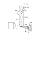
- FIG. 11A is a schematic diagram showing a beam current detection plate 21d provided with a conductive target and a nozzle insertion mechanism in the present embodiment.
- FIG. 11B is a schematic diagram showing beam current detection by the beam current detection plate 21d provided with the conductive target 27 and the nozzle insertion mechanism in the present embodiment.
- the beam current detection plate 21d of this embodiment is provided with a conductive target 27 such as carbon at the lower part (tip portion) of the beam current detection plate 21 of the first embodiment (see FIG. 11A).
- the detection method of the ion beam B is the same as that in the first embodiment (see FIG. 11B).
- beam current detection plates generally require a metal material that is difficult to be sputtered because they require conductivity and strength against ion beams. If the beam current detection plate is formed of the same material as the conductive target, the entire beam current detection plate needs to be replaced when it is consumed due to the coating. By configuring as in the present embodiment, the ion milling apparatus can be easily maintained and the target can be exchanged according to the sample.
- the beam current detection plate 21d When coating the sample S, the beam current detection plate 21d is moved so that the target 27 is positioned in front of the opening (injection port) of the ion gun 1. By irradiating the target 27 with the ion beam B, the material constituting the target 27 is sputtered (see FIG. 11C). The sputtered particles uniformly adhere to the surface of the sample S.
- the conductive coating film C having an arbitrary film thickness can be formed on the surface of the sample S by adjusting the irradiation time (sputtering) time of the ion beam B. Since the coating by sputtering of the ion beam B is not accompanied by heating, thermal damage to the sample S can be reduced as compared with the coating by the conventional resistance heating method.
- the target 27 it is preferable to arrange the target 27 around 70 ° with respect to the ion beam B. By arranging in this way, the sputtering efficiency is increased.
- the angle of the target 27 with respect to the ion beam B may be adjusted by inclining the beam current detection plate 21d itself that processes the shape of the target 27.
- coating with different particle diameters can be achieved.
- the coating may be performed while rotating the sample stage or continuously changing the angle. As a result, it is possible to uniformly coat even a sample with severe irregularities.
- FIG. 12 is a schematic diagram centering on the sample chamber 5 of the ion milling apparatus 100e in the present embodiment.
- the ion gun 1 (not shown) and the gas injection nozzle 2 (not shown) exist on the side of the sample chamber 5, that is, on the front side of the paper surface.
- the sample holding member 31 includes a sample table 32 that fixes the sample S, and a shielding unit 33 that shields a part of the sample S fixed to the sample table 32.
- the sample stage 32 and the shielding part 33 may be integrally formed.
- FIG. 12 shows a state in which the sample stage 32 and the shielding part 33 are integrally formed.
- the sample holding member 31 further includes a sample stage drive unit (not shown) that rotates the sample stage 32 and a shielding unit position adjusting unit (not shown) that adjusts the shielding positional relationship between the shielding unit 33 and the sample S.
- a sample shielding unit 34 and a sample shielding unit fine movement mechanism 35 that can drive the sample shielding unit 34 perpendicularly to the ion beam B may be included.
- the sample holding member installation portion 41 is provided with a rotating body 42 on which the sample holding member 31 (a member that holds the sample S including the sample shielding unit fine movement mechanism 35) can be mounted.
- the rotating body 42 functions as a support base that supports the sample holding member 31.
- the sample holding member installation unit 41 includes, for example, a rotating body 42, a gear (not shown), and a bearing (not shown).
- the sample shielding unit fine movement mechanism 35 is provided with a shielding unit fixing portion 43 on the rear surface of the sample shielding unit fine movement mechanism 35.
- the sample shielding unit fine movement mechanism 35 is mounted on the sample holding member installation part 41 by contacting the fixed surface (rear surface) of the sample shielding unit fine movement mechanism 35 with the upper surface of the rotating body 42 of the sample holding member installation part 41. Screws are fixed by the fixing portion 43.
- the entire sample holding member installation section 41 is not rotated and tilted, and an arbitrary angle with respect to the optical axis of the ion beam B irradiated from the side surface direction of the sample chamber 5 by the rotating body 42 mounted on the sample holding member installation section 41. It can be rotated and tilted.
- the direction and angle of rotation are controlled by a sample holding member driving unit (not shown).
- the method of rotating and tilting the rotating body 42 by the sample holding member driving unit can be any method.
- the sample S installed on the sample shielding unit fine movement mechanism 35 is rotated by tilting the rotating body 42 of the sample holding member installation unit 41 by the sample holding member driving unit provided below the sample holding member installation unit 41.
- a predetermined angle can be set with respect to the optical axis of the ion beam B.
- the sample shielding unit fine movement mechanism 35 is configured to be movable in the front-rear and right-and-left directions perpendicular to the optical axis of the ion beam B, that is, in the X and Y directions.
- the sample holding member installation portion 41 is disposed on a flange 52 that also serves as a part of the wall of the sample chamber 5.
- the flange 52 is configured to be pulled out along the linear guide 53. That is, the sample holding member installation portion 41 is pulled out from the sample chamber 5 along the linear guide 53.
- the sample shielding unit fine movement mechanism 35 provided with the sample shielding unit 34 has a configuration that is detachably fixed to the sample holding member installation portion 41.
- the sample shielding unit fine movement mechanism 35 including the sample shielding unit 34 is mounted on the sample holding member installation unit 41 by drawing the sample holding member installation unit 41 from the sample chamber 5.
- the sample shielding unit fine movement mechanism 35 including the sample shielding unit 34 mounted on the sample holding member installation unit 41 is pulled out of the sample chamber 5
- the sample shielding unit fine movement mechanism 35 including the sample shielding unit 34 is The holding member installation unit 41 is detachable. This attachment and detachment is performed manually or with an appropriate instrument.
- sample shielding unit 34 body The configuration of the sample shielding unit 34 body will be described.
- sample stage 32 and the sample stage rotation mechanism (not shown), the shielding part 33, and a shielding part position adjusting part (not shown) for finely adjusting the shielding positional relationship between the shielding part and the sample. Is integrally formed as a sample shielding unit 34 (main body).
- the sample table rotation mechanism (not shown) includes a sample table rotation ring and a sample table rotation screw, and is configured to rotate the sample table 32 perpendicular to the optical axis of the ion beam B.
- the sample stage rotation ring is configured to rotate by turning a sample stage rotation screw, and is configured to return in reverse rotation by the elastic force of the elastic body.
- the sample shielding unit 34 includes a mechanism that can finely adjust the position and rotation angle of the shielding portion 33, and can be attached to and detached from the sample shielding unit fine movement mechanism 35.
- the sample shielding unit 34 and the sample shielding unit fine movement mechanism 35 are composed of two parts, but may be composed of one part.
- the shielding part 33 is fixed to a shielding part holding part (not shown) by a shielding part fixing screw (not shown).
- the shielding part holding part moves along the linear guide 53 by operating the shielding part fine adjustment mechanism (that is, the shielding position adjustment part). Thereby, the position of the sample S and the shielding part 33 is finely adjusted.
- the sample stage 32 is inserted and fixed to a sample stage rotating ring (not shown) from the lower side.
- the sample S is bonded and fixed to the sample table 32.
- the position of the sample table 32 in the height direction is adjusted by a sample table position control mechanism (not shown), and the sample table 32 is brought into close contact with the shielding part 33.
- a method for making the cross section of the sample S parallel to the shielding part 33 will be described.
- the position is adjusted by turning a sample stage rotation screw (not shown), and fine adjustment is performed under the microscope so that the cross section of the sample S and the ridge line of the shielding portion 33 are parallel to each other.
- the setting is made by turning the shielding portion fine adjustment mechanism (not shown) so that the cross section of the sample S slightly protrudes from the shielding portion 33, for example, about 50 ⁇ m.
- the sample holding member installation unit 41 is provided with a rotation function (rotating body 42), and an inclination mechanism having an inclination axis perpendicular to the central axis of the ion beam B is provided. Is provided. Furthermore, the ion milling apparatus 100e according to the present embodiment is provided with an eccentric mechanism that shifts the central axis of the ion beam B and the rotation axis of the sample shielding unit fine movement mechanism 35 when the tilt angle is 90 degrees.
- the cross-section milling (apparatus for milling the sample S through a mask and creating a smooth surface)
- Planar milling smooth machining of a surface perpendicular to the ion beam axis (when the tilt angle of the sample holder is 90 degrees) is possible).
- the ion milling apparatus 100e includes a central axis of the ion beam B and a first axis on the sample holding member installation portion 41 having a first rotation axis that exists in a plane perpendicular to the central axis of the ion beam B.
- a second rotation axis that is perpendicular to each of the one rotation axes can be rotated, rotated about the center of tilt, or reciprocating tilt drive. That is, the sample holding system 3 of the present embodiment performs the reciprocating tilt driving at the time of cross-sectional milling and the rotation or reciprocating tilt driving of the sample S at the time of planar milling by the sample holding member installation portion 41 (rotating mechanism). It is characterized by that.
- the ion gun 1 (not shown) is installed on the side of the sample chamber 5 (the front side of the paper).
- the reason for such a configuration is that the sample holding member installation portion 41 can be in a stable state when the sample holding member installation portion 41 (stage 51) is not inclined (for example, during cross-sectional milling).
- the sample holding member installation portion 41 In order to perform cross-section processing in a non-tilted state of the sample holding member installation portion 41, it is necessary to irradiate the ion beam B from the side, and the ion gun 1 is installed on the side of the sample chamber 5 for that purpose.
- a processing observation window 54 for confirming the processing cross section was installed above the sample chamber 5 (in a gravitational environment, the direction opposite to the direction of the gravitational field). According to such a configuration, it is possible to check the processing cross section at the time of cross-section milling and the processing surface at the time of plane milling with one processing observation window 54.
- a shutter 55 is provided between the processing observation window 54 and the sample S.
- the shutter 55 is installed to prevent sputtered particles from accumulating on the processing observation window 54.
- the ion milling apparatus 100e in this embodiment may be provided with the optical microscope and electron microscope which observe the shielding positional relationship of the shielding part 33 and the sample S other than the processing observation window 54 in which vacuum sealing is possible. . These may be exchangeably provided in an opening (processing observation window 54) provided in the sample chamber 5.
- the operation unit 62 includes a processing mode setting unit, a sample stage operation condition setting unit, a rotation mechanism operation condition setting unit, and a gas injection condition setting unit.
- the processing mode setting section provided in the operation section 62 has buttons for selecting either flat milling (Flat) or cross-section milling (Cross-section). Is possible.
- the sample stage operating condition setting unit is provided with a button for selecting either tilt or reciprocating tilt (swing), and either one can be selected alternatively.
- the sample stage operating condition setting unit is further provided with a setting unit for setting an inclination angle or an angle range (Angle) of the reciprocating inclination and a periodic speed (Speed) in the case of the reciprocating inclination.
- the rotating mechanism operating condition setting unit (not shown) is provided with a setting unit for setting a reciprocating inclination angle (Angle) by the rotating mechanism and a periodic speed (Speed) of the reciprocating inclination.
- the sample stage is a sample holding member driving unit of the sample holding system 3
- the rotation mechanism is a rotating body 42 constituting the sample holding member installation unit 41 of the sample holding system 3.
- a gas injection condition setting part sets conditions about maintenance of ion gun 1 by gas injection of injection gas from gas injection nozzle 2 like a 1st embodiment.
- the cross-section milling process requires the reciprocating tilt driving of the rotating body (rotating mechanism) 42, but does not require the reciprocating tilt driving of the sample holding member installation portion 41. Therefore, when the cross-section milling process is selected (Cross-Section button is selected), the control system 6 of the ion milling apparatus 100e is configured to prohibit or invalidate the setting in the sample stage operating condition setting unit. good. Further, if the sample stage 32 is tilted during the cross-section milling, the ion beam B is irradiated to a portion unrelated to the processing target, or the cross section of the sample S is processed obliquely.
- control is performed so as not to irradiate the ion beam B, or a warning is issued to alert the user. You may do it. Further, the control may be performed so that the inclination angle of the sample stage 32 becomes zero.
- the sample stage operation condition setting unit (not shown) and the rotation mechanism operation condition setting unit ( It is necessary to validate both inputs (not shown).
- the rotating body 42 performs both reciprocating tilt driving at the time of cross-sectional milling and rotational driving at the time of planar milling, so that one ion milling apparatus 100e has two different types. Milling is possible.
- whether to perform cross-section milling or planar milling is selected by selecting a processing type using a changeover switch provided in the operation unit 62.
- the present invention is not limited to this.
- a sensor for recognizing the shape of the sample holding member 31 is provided, and a signal of the recognition result is transmitted to the arithmetic processing unit so that the control unit 61 performs the processing without the user's operation. You may make it choose a kind.
- the processing type selection in the operation unit 62 is compared with the device state, and when the selection or the device state is not appropriate, the arithmetic processing unit transmits a warning signal to the output unit to the user. An alarm may be generated. Thereby, the user can avoid the processing based on an erroneous condition.
- the unit 61 may switch the processing type. Furthermore, when there is a contradiction between the position setting of the sample stage and the selection of the processing type, the control unit 61 may issue a predetermined signal to issue a warning. Also in this case, it is possible to suppress erroneous setting by performing the setting through the steps illustrated in FIG. 12 to be described later. Further, the processing unit may control the position of the sample stage by selecting the processing type.
- FIG. 13 is a flowchart for comparing the processing type of the ion milling method according to this embodiment with the state of the ion milling apparatus, and displaying a message prompting the operator to set an accurate apparatus.
- the user of the ion milling method in the present embodiment inputs the type of processing at the operation unit 62 after arranging the sample S to be processed in the sample chamber 5 (S21).
- the control unit 61 determines which processing is selected (S22), and determines whether the sample holding member 31 corresponding to the selected processing is installed in the sample holding member installation unit 41 (S23, Or, S26).
- Whether the predetermined sample holding member 31 is installed is determined by providing a sensor in the sample chamber 5 for determining the difference between them and whether the sample holding member 31 is installed.
- the control unit 61 passes the output unit through the output unit. Then, a predetermined signal is transmitted to the display unit 63 and a warning is issued (S30).
- a display such as “Err” may be displayed on the display unit 63, or another display means or an alarm generator may be used.
- the control unit 61 determines whether the sample holding member 31 is installed (S23), and then tilts the sample stage 51 (sample holding member installation unit 41). It is determined whether the angle is zero (S24). If it is not zero, a predetermined signal is transmitted to the display unit 63 via the output unit, and a warning is issued. By generating such a warning, it is possible to grasp that the state of the sample holding member 31 is not suitable for cross-sectional milling, and it is possible to suppress a situation in which erroneous processing is performed. After confirming that the tilt angle of the sample stage 32 is set appropriately, the control unit 61 shifts to a state in which it is possible to input conditions for the reciprocating tilt drive of the rotating body 42 (S25).
- both the tilting stage 51 and the rotating body 42 (rotating mechanism) are driven, so that the condition of both can be set (S27). .
- control unit 61 determines that other conditions (ion beam current, processing time, etc.) to be set are set (S28), and starts processing (S29).
- the control unit 61 controls the sample holding member installation unit 41 (sample holding) so as to be in a non-inclined state. You may make it control a member drive part.
- control unit 61 recognizes the processing type setting information, the type of the mounted sample holding member 31 and the state of the apparatus, and compares the information to determine the current setting state. It can be easily determined whether or not it is appropriate. Therefore, it is possible to prevent processing based on an incorrect setting.
- Modification 1 This modification is a modification in which the beam current detection plate used for inserting the gas injection nozzle is changed from the first embodiment, and the gas injection nozzle is not provided in the beam current detection plate without providing the nozzle insertion port and the gas nozzle port. It is a form to arrange.
- the gas injection nozzle 2 is inserted into the ion gun 1 using the gas nozzle port 23 provided in the beam current detection plate 21.
- a tubular member is provided along the side surface of the beam current detection plate, and the end portion of the tubular member is a gas nozzle port.
- the beam current detection plate not only moves up and down in the vertical direction, but also moves left and right in the horizontal direction.
- the beam current detection plate has a horizontally long shape, and a tubular member may be provided along the side surface of the beam current detection plate, and the end may be a gas nozzle port. In this configuration, the beam current detection plate moves left and right at least on one axis in the horizontal direction.
- the beam current detection plate may be provided with a tubular member along the back surface, and the end of the tubular member may be disposed at the lower end of the beam current detection plate, and the end may be configured as a gas nozzle port. In this configuration, the beam current detection plate moves left and right at least on one axis in the horizontal direction.
- the beam current detection plate may have a horizontally long shape, a tubular member may be provided along the back surface, an end of the tubular member may be disposed at the lower end, and the end may be configured as a gas nozzle port. In this configuration, the beam current detection plate may move not only in the vertical direction but also in the horizontal direction.
- the beam current detection plate may be configured as a gas nozzle port by disposing an end portion of a tubular member separate from the beam current detection plate at the top.
- the gas injection nozzle 2 is inserted into a gas nozzle port through a tubular member. In any case, there is no difference from the first embodiment in the effect of processing (removing) the deposit by injecting the injection gas.
- the sample holding system is not moved at the time of gas injection. However, even if the sample holding system is retracted from the processing position and the gas injection nozzle is directly inserted into the opening (injection port) of the ion gun. Good. Further, the gas injection nozzle may be inserted from the opening of the ion gun to the inside of the ion gun.
- the gas injection nozzle 2 is preferably formed of a material that is not easily deformed by an external stress having an appropriate elasticity that can be inserted into the ion gun from the opening of the ion gun. Further, the gas injection nozzle 2 may be formed of a material that is not easily deformed by its own weight or injection of injection gas. Examples of the material forming the gas injection nozzle 2 include a polyethylene resin, a polypropylene resin, and a fluorine resin.
- Such a configuration makes it difficult for the insertion position to be displaced due to deformation of the gas injection nozzle 2 and the like, and the insertion accuracy of the gas injection nozzle 2 is increased. And it becomes easy to control the gas injection position, and it becomes easier to process (remove) the deposit D.
- Modification 3 In this modification, the short circuit of the electrode and the discharge instability occur between the step of injecting the gas toward the acceleration electrode in the first embodiment (S14) and the step of inserting the gas injection nozzle into the ion gun (S15). It is the form which provided the step which confirms whether it eliminated or not.
- the control unit 61 monitors the current of the beam B at the detector in the beam current detection region 22 of the beam current detection plate 21 connected to the input unit. If the current flowing through the detector in the beam current detection region 22 is not less than a predetermined value with the discharge voltage applied to the ion gun 1, it is determined that the short circuit between the electrodes of the ion gun 1 has been eliminated.
- the current flowing through the acceleration electrode 14 and the acceleration power source 82 is measured by a sensor constituting the input unit, the current value becomes smaller than a predetermined current value, and the current flowing through the cathode 13 and the acceleration power source 82 is measured. When the current value becomes smaller than the predetermined current value, it is determined that the short circuit has been eliminated between the sword 13 and the acceleration electrode 14.
- control unit 61 monitors the current of the beam B at the detector in the beam current detection region 22 of the beam current detection plate 21 connected to the input unit.
- a predetermined time for example, 5 minutes
- a predetermined value for example, less than 5%
- the current flowing through the accelerating electrode 14 and the accelerating power source 82 is measured by the sensor constituting the input unit, and the fluctuation range of the current in a predetermined time (for example, 5 minutes) becomes small (for example, 5% or less), and the cathode 13 And the current flowing through the acceleration power source 82 is measured, and when the fluctuation range of the current in a predetermined time (for example, 5 minutes) becomes small (for example, 5% or more), it is determined that the discharge of the ion gun 1 is stable. .
- the control unit 61 When the controller 61 determines that the short circuit and the discharge instability have been resolved, the control unit 61 resumes the temporarily suspended processing.
- an ion gas is injected to maintain the ion gun.
- the ion gun may be maintained by injecting an injection gas into the ion gun in the same procedure when the ion milling apparatus is turned on.
- a deposit deposited on the ion gun may be treated (removed) by injecting an injection gas in the same procedure after the ion beam processing is completed.
- the gas injection nozzle 2 is inserted into the ion gun 1 using the beam current detection plate 21.
- the gas injection nozzle 2 may be inserted into the ion gun 1 using a robot arm, for example, without using the beam current detection plate 21. Even if it is this structure, there is no difference in the effect of invention.
- Modification 7 This modification is a modification in which the ion gun in the first embodiment is changed to a cold cathode type DC discharge (glow discharge) type ion gun.
- the ion gun used in this modification includes an anode, a cathode, an insulator that insulates the anode and the cathode, and an ionization chamber.
- the ion gun used in this modification has, for example, a bottomed cylindrical ionization chamber.
- This ionization chamber includes an anode (on the central axis in the ion beam ejection direction) at the center of the opening serving as the ion beam ejection port.
- the ion gun includes a cathode provided with an opening serving as an ion beam outlet at the center on the central axis in the ion beam emission direction.
- the anode and the cathode are insulated by an insulator.
- the ionization chamber supports an anode, a cathode, and an insulator, and has an inlet for a discharge gas (inert gas) such as a rare gas.
- a discharge gas inert gas
- the anode and cathode are connected to a power supply system.
- Ion beam ejection is performed as follows. A high voltage is applied between the anode and cathode electrodes insulated by an insulator in the ionization chamber. An inert gas is introduced into the ionization chamber so that the pressure is suitable for discharge. This causes glow discharge between both electrodes. Some of the ions of the inert gas generated by the glow discharge are emitted as an ion beam from an opening provided in the cathode, which is a cathode.
- Modification 8 This modification is a modification in which the ion gun in the first embodiment is changed to a hot cathode type DC discharge (arc discharge) type ion gun.
- the ion gun used in this modification includes a plasma generation chamber, an anode, a cathode, a solenoid coil, and an extraction electrode.
- the shape of the plasma generation chamber is not limited, and is, for example, a bottomed cylindrical shape.
- the plasma generation chamber has an inlet for introducing an inert gas.
- the plasma generation chamber includes a cathode at the center of the bottom (on the central axis in the ion beam emission direction).
- the plasma generation chamber is provided with an anode on the inner surface of the cylinder.
- the cathode is preferably an electrode that emits thermal electrons, such as a filament.
- the cathode may be composed of a plurality of filaments and the like.
- the extraction electrode has an opening through which the ion beam is extracted. The number of openings is not limited.
- the cathode is connected to an electrode power source so that a negative terminal is located on the outer side (side closer to the inner wall of the plasma generation chamber), and a predetermined voltage is applied.
- the anode is connected to the positive electrode side of the arc power source, and the negative electrode side is connected to the positive electrode side of the electrode power source to apply an arc voltage.
- Ion beam ejection is performed as follows.
- An inert gas is introduced into the plasma generation chamber so as to obtain a pressure suitable for discharge in a state where a current flows from the electrode power source to the cathode and thermoelectrons are generated.
- An arc voltage is applied to cause arc discharge between the anode and cathode electrodes in the plasma generation chamber.
- the inert gas molecules collide violently with the thermoelectrons and are ionized to be ionized.
- inert gas ions, electrons, and inert gas are mixed, and plasma having a neutral charge as a whole exists.
- Some of the ions of the generated inert gas are attracted by the extraction electrode provided in the opening of the plasma generation chamber, and are emitted as an ion beam from the opening of the extraction electrode.
- a cusp magnetic field is formed in the vicinity of the inner wall of the plasma generation chamber by a solenoid coil disposed around the plasma generation chamber. This cusp magnetic field increases the flight distance of electrons and increases the ionization rate.
- the generation of plasma in the entire plasma generation chamber increases the flight distance until electrons from the cathode (thermoelectrons emitted from the filament) reach the anode, and there is a probability of colliding with inert gas molecules in the plasma generation chamber. It becomes high and becomes advantageous in producing high-density plasma.
- the extraction electrode may have a large number of apertures (holes) provided uniformly over the entire surface. Furthermore, the deceleration electrode may be disposed to face the acceleration electrode at a predetermined interval, and the apertures (holes) of both electrodes may be matched. Further, the acceleration electrode and the deceleration electrode may be slightly bent at the center so that the center bulges toward the sample chamber.
- the heater may be formed in a ring shape that extends substantially all around the acceleration electrode and the deceleration electrode, and may be attached to both surfaces of each electrode. You may comprise so that the peripheral part of an acceleration electrode and a deceleration electrode may be inserted
- Modification 9 This modification is a modification in which the ion gun in the first embodiment is changed to a high frequency discharge ion gun.
- the ion gun used in this modification includes a plasma generation chamber, a plasma expansion chamber, a high-frequency coil, and an extraction electrode.
- the shape of the plasma generation chamber is not limited.
- the plasma generation chamber has a bottomed cylindrical shape and is made of quartz.
- the plasma generation chamber is formed by winding a high frequency coil.
- the plasma generation chamber includes an inlet for introducing an inert gas that is a discharge gas.
- the plasma expansion chamber is connected to the plasma expansion chamber.
- the plasma expansion chamber is formed with a larger diameter than the plasma generation chamber.
- multipolar permanent magnets are arranged on the outer periphery. The permanent magnets are arranged so that the opposite poles are adjacent.
- An extraction electrode is disposed between the plasma expansion chamber and the sample chamber.
- the extraction electrode is formed in a disk shape with a conductive material.
- the extraction electrode is preferably formed of a high melting point material such as molybdenum or tungsten.
- the extraction electrode is composed of an acceleration electrode and a deceleration electrode.
- the accelerating electrode and the decelerating electrode are arranged to face each other with an interval in this order from the plasma expansion chamber to the sample chamber.
- the distance between the acceleration electrode and the deceleration electrode is, for example, about 1.5 mm to 2.0 mm.
- a number of extraction holes through which the ion beam passes may be formed in the acceleration electrode and the deceleration electrode.
- the extraction holes of the acceleration electrode and the deceleration electrode may have substantially the same diameter, or may be different from each other.
- the extraction holes of the acceleration electrode and the deceleration electrode are arranged so as to overlap in plan view, and are arranged so that the ion beam is extracted to the sample chamber without loss.
- the plasma generation chamber, plasma expansion chamber, and sample chamber are exhausted by the exhaust means. After exhausting, a discharge gas (inert gas) is supplied to the plasma generation chamber.
- the high frequency coil is connected to a high frequency power supply and supplied with high frequency power.
- the discharge gas is turned into plasma.
- the generated plasma expands into the plasma expansion chamber.
- Permanent magnets contain plasma in a plasma expansion chamber by a magnetic field, and increase the ionization rate by applying a magnetic field to the discharge region to increase the flight distance of ions.
- the acceleration electrode is connected to an acceleration power source, and a voltage of, for example, 500 V to 2000 V is applied.
- the deceleration electrode is connected to a deceleration power source and is applied with a voltage of ⁇ 100V to ⁇ 500V.
- a ground electrode may be provided on the sample side as an extraction electrode. The ground electrode is applied with a voltage of less than ⁇ 100 V with respect to the ground or the ground. Thereby, the ion beam is stably extracted.
- the ions are attracted from the plasma expanded into the plasma expansion chamber to the extraction hole of the acceleration electrode.
- the attracted ions are emitted as an ion beam through the extraction holes of the acceleration electrode and the deceleration electrode.
- This modification is a modification in which the ion gun in the first embodiment is changed to a microwave discharge ion gun.
- the ion gun used in this modification includes a plasma generation chamber, a plasma expansion chamber, a solenoid coil, a magnet, and acceleration means.
- the shape of the plasma generation chamber is not limited, and is, for example, a cylindrical shape.
- the plasma generation chamber has an inlet for introducing an inert gas.
- a microwave transmission window is provided at one end of the plasma generation chamber.
- the microwave generated by the microwave generator is introduced into the plasma generation chamber via, for example, a waveguide.
- the wall surface of the plasma generation chamber is made of stainless steel, for example.
- a plasma expansion chamber is connected to the other end of the plasma generation chamber in an airtight manner.
- the space in the plasma generation chamber communicates with the space in the plasma expansion chamber.
- a solenoid coil is disposed around the plasma generation chamber. This coil generates a magnetic field parallel to the propagation direction of the microwave introduced from the transmission window in the plasma generation chamber.
- the shape of the plasma expansion chamber is not limited, and is, for example, a cylindrical shape.
- a large number of magnets are arranged around the plasma expansion chamber so that the magnetic poles alternate.
- An ion extraction electrode is provided in a portion where the plasma expansion chamber and the processing chamber communicate with each other.
- a 2.45 GHz microwave is introduced while introducing argon gas into the plasma generation chamber, an argon gas plasma is generated due to the interaction between the microwave and the magnetic field.
- the plasma of argon gas generated in the plasma generation chamber passes through the plasma expansion chamber that expands the plasma, and is extracted as an ion beam by an extraction electrode that accelerates ions in the plasma in the plasma expansion chamber.
- the ion gun in the first to seventh embodiments may be configured to be replaceable for disassembly and maintenance.
- the number of ion guns is not limited to one, and a plurality of ion guns may be provided. Even if it is this structure, there is no difference in the effect of invention.
Landscapes
- Chemical & Material Sciences (AREA)
- Analytical Chemistry (AREA)
- Engineering & Computer Science (AREA)
- Physics & Mathematics (AREA)
- Plasma & Fusion (AREA)
- Combustion & Propulsion (AREA)
- Electron Sources, Ion Sources (AREA)
Abstract
Description
しかし、特許文献1に記載の発明は、堆積物の処理について考慮していない。
上記した以外の課題、構成及び効果は、明細書中において説明する。
図1は、本実施形態におけるイオンミリング装置100の構成を示す概略図である。
試料保持部材31は、任意の手段により試料Sを保持する部材である。試料保持部材設置部41は、試料保持部材31が設置され、試料室5が大気圧に開放されたときに試料室5の外へ引き出すことができる様に構成されている。試料保持部材駆動部44は、試料保持部材31が所定の方法により駆動可能に構成されている。即ち、試料保持系3は、試料室5の内部で試料Sを保持する。
粗引きポンプは、高真空ポンプが運転可能な圧力まで真空引き可能なポンプである。粗引きポンプとしては、例えば、135/162L/min(単相100V50/60Hz)の排気容量である真空ポンプが挙げられる。高真空ポンプとしては、例えば、ターボ分子ポンプが挙げられる。
イオンガン1は、アノード11と、アノード11を挟み込む様に配置された一対のカソード12、13と、加速電極14と、磁石15と、ガス導入口16と、を含んで構成される。
又、アノード11は、インシュレータ(図示省略)により、カソード12、カソード13、及び、磁石15に対して電気的に絶縁されている。
イオンガン1に導入される放電ガス(イオン化ガス)は、例えば、アルゴン、ヘリウム、キセノン等の希ガスが挙げられる。
イオンガン1のイオン化室17内のアノード11に囲まれた空間にガス導入口16により放電ガスGを導入する。イオンガン1のイオン化室17内のアノード11に囲まれた空間において、適切ガス分圧を保った状態で、放電電源81によりアノード11とカソード12、13間に数kV程度の電圧を印加する。アノード11は、カソード12及びカソード13に対して正の電圧が印加される。カソード12、13は、アノード11に対して負の電圧が印加され、表面から電子を放出する。
例えば、図5Aに示す様に、本実施形態におけるビーム電流検出板21は、イオンガン1の対向面にビーム電流検出領域22、ビーム電流遮断領域26、ガスノズル口23をこの順に備え、試料S側(反対側)にノズル挿入口25、ノズル固定冶具24を備える。
ガス噴射ノズル2は、例えば、ネジが切ってある部分を有し、このネジ部分と噛み合い対をなす歯車の回転により、少なくとも鉛直方向の1軸上を移動可能(上下動可能)に構成される。これらネジ部分は、例えば、外周にネジが切ってある円筒形の別体の部材(歯車)をガス噴射ノズル2に挿通することで構成されてもよい。
前記のとおり、制御系6は、制御部61と、操作部62と、表示部63と、を含んで構成される。制御部61は、演算処理部、記憶部、入力部、及び、出力部を含んで構成される。
制御部61は、イオンガン1内を整備中である旨を表示する信号を出力部に伝達し、出力部の表示等により使用者に知らせてもよい。
制御部61は、ビーム電流検出板21の移動に合わせて、ガス噴射ノズル2を繰り出して、イオンガン1の開口に近付けてもよい。
堆積物Dのイオンガン1からの排出については、後記する実施形態4で説明する。
制御部61は、真空引き系7に信号を送信して真空引き系7のポンプによりイオンビームBが射出可能な圧力まで試料室5内及びイオンガン1内を真空引きする(S8)。高真空引き用のポンプの作動は、試料室5内の状態が安定した後でもよい。
制御部61は、入力部を構成する圧力センサによって、試料室5内が真空引きされていることを確認する。
そして、制御部61は、加工条件の入力、加工開始ボタンの押下等使用者による操作を待つ(待機)。
ここでは、試料加工中における堆積物Dの検知、及び、堆積物Dの処理について説明する。
加速電極14と加速電源82に流れる電流を測定して、所定時間(例えば、5分間)における電流変動が大きくなった場合(例えば、5%以上)は、イオンガン1の放電が不安定であると判定してもよい。
なお、イオンガン1の状態の確認は、試料Sの加工と並行して1分ごと、3分ごと等適宜時間間隔を空けて行ってもよい。
なお、ビーム電流検出板21の移動(S12)と、ガス噴射ノズル2の繰り出し(S13)は、同時に行ってもよい。
堆積物Dのイオンガン1からの排出については、後記する実施形態4で説明する。
なお、ビーム電流検出板21の移動と、ガス噴射ノズル2の繰り出しは、同時に行ってもよい。
又は、制御部61は、イオンガン1に放電電圧を印加して電極間の短絡やイオンガン1の放電の不安定がない(前記電極間の短絡や放電の不安定の判断基準に該当しない)ことを確認してから、一時中断した試料Sの加工を再開してもよい。
更に、制御部61は、試料Sの加工の失敗を防止するため、安全のため、試料Sの加工を中断すると共に、その旨を表示部63に表示してもよい。
本実施形態は、ガス噴射ノズルの挿入位置を第1実施形態から変更した形態であり、イオンガンの開口とは反対側に位置するカソード12aにガス噴射ノズルの挿入口18aを設けて、イオンガン1aの内部にガス噴射ノズル2aを挿入する形態である。
図8Aは、本実施形態におけるガス噴射ノズル挿入口18aをカソード12aに設けたイオンガン1aのカソード12aを示す概略模式図である。図8Bは、本実施形態におけるガス噴射ノズル挿入口18aをカソード12aに設けたイオンガン1aの断面模式図である。
イオンガン1の開口とは反対側に位置するカソード12aにガス噴射ノズル2の挿入口18aを設けることで、アノード11とカソード12aの近傍に噴射ガスJを噴射しやすくなり、噴射ガスJの噴射圧力を低くすることが可能となる(図8B参照)。噴射ガスJの噴射圧を低くすることで、アルゴン等の噴射ガスJの使用量を削減できる。アノード11とカソード12aを短絡する堆積物(図示省略)がガス噴射ノズル2aによるガス噴射により処理(除去)されやすくなる。
本実施形態は、ガス噴射ノズルの挿入位置を第1実施形態から変更した形態であり、イオンガン1bの磁石15bにガス噴射ノズル2bの挿入口18bを設けてイオンガン1bの内部にガス噴射ノズル2bを挿入する形態である。
図9は、本実施形態におけるガス噴射ノズル挿入口18bを磁石15bに設けたイオンガン1bの断面模式図である。
本実施形態は、イオンガンに堆積物の排出口を設けた形態であり、イオンガンの磁石に排出口(排気口)を設けた形態である。
図10Aは、本実施形態における磁石15cに排出口を設けたイオンガン1cを示す概略模式図である。図10Bは、本実施形態におけるにおけるイオンガン1cの磁石15cを示す概略模式図である。
なお、堆積物Dの排出口19は、本発明の必須の構成要件ではない。
本実施形態は、ビーム電流検出板にコーティング用のターゲットを備えた形態である。
コーティングは、試料台を回転しながら、又は、角度を連続的に変えながら行ってもよい。これにより、凹凸の激しい試料に対しても均一にコーティングすることが可能となる。
本実施形態は、1台のイオンミリング装置で2種類の異なるミリング加工を可能とする形態である。本実施形態における試料保持系3は、断面ミリング加工と平面ミリング加工の両方を行うことができる。
この着脱は、人手によって、若しくは適当な器具によって行う。
操作部62には、加工モード設定部、試料台動作条件設定部、回転機構動作条件設定部、ガス噴射条件設定部が備わる。
本実施形態は、第6実施形態におけるイオンミリング方法において、制御部61で加工の種類に対応した適切な試料保持部材31であるか確認を行う実施形態である。
図13は、本実施形態におけるイオンミリング方法の加工種類とイオンミリング装置の状態を比較して、正確な装置設定を操作者に促す表示をするためのフローチャートである。
ここで、制御部61は、いずれの加工が選択されたか判断し(S22)、選択された加工に見合った試料保持部材31が試料保持部材設置部41に設置されているかを判断する(S23、又は、S26)。
制御部61は、試料台32の傾斜角が適正に設定されていることを確認した上で、回転体42の往復傾斜駆動の条件の入力を可能とする状態に移行する(S25)。
又、試料保持部材設置部41(ステージ51)が傾斜していた場合(傾斜角0°以外の場合)、非傾斜状態となる様に、制御部61は、試料保持部材設置部41(試料保持部材駆動部)を制御する様にしても良い。
本変形例は、ガス噴射ノズルの挿入に利用するビーム電流検出板を第1実施形態から変更した変形例であり、ビーム電流検出板にノズル挿入口、ガスノズル口を設けることなく、ガス噴射ノズルを配置する形態である。
ビーム電流検出板は、横長の形状であり、ビーム電流検出板の側面に沿って管状の部材を設け、端部をガスノズル口とした構成としてもよい。この構成の場合、ビーム電流検出板は、少なくとも水平方向の1軸上を左右動する。
ビーム電流検出板は、同様に、横長の形状であり裏面に沿って管状の部材を設け、下端に管状の部材の端部を配置し、端部をガスノズル口として構成してもよい。この構成の場合、ビーム電流検出板は、鉛直方向を上下動するだけではなく、水平方向を左右動してもよい。
いずれの場合であっても、噴射ガスを噴射して堆積物を処理(除去)する効果に第1実施形態との差異はない。
第1実施形態においては、ガス噴射の際に試料保持系を移動させていないが、試料保持系を加工位置から退避させて、ガス噴射ノズルをイオンガンの開口(射出口)に直接挿入してもよい。又、ガス噴射ノズルをイオンガンの開口からイオンガンの内部まで挿入してもよい。
本変形例は、第1実施形態における加速電極に向けてガスを噴射するステップ(S14)と、ガス噴射ノズルをイオンガン内に挿入するステップ(S15)の間に、電極の短絡及び放電不安定が解消したか否か確認するステップを設けた形態である。
第1実施形態においては、試料Sのイオンミリング(イオンビーム加工)前に噴射ガスを噴射してイオンガンの整備を行っている。しかし、イオンミリング装置の電源投入時に同様の手順で噴射ガスをイオンガン内部に噴射して、イオンガンの整備を行ってもよい。イオンビーム加工終了後に同様の手順で噴射ガスを噴射して、イオンガンに堆積した堆積物を処理(除去)してもよい。
第1実施形態においては、ビーム電流検出板21を利用してガス噴射ノズル2をイオンガン1の内部に挿入している。しかし、ビーム電流検出板21を利用することなく、例えば、ロボットアームを利用してガス噴射ノズル2をイオンガン1の内部に挿入してもよい。この構成であっても、発明の効果に差異はない。
第1実施形態においては、噴射ガスの噴射による堆積物の処理を制御系6の制御により行う場合について説明したが、使用者が必要に応じて堆積物の処理を行う様に構成してもよい。この場合、操作部62に手動開始用のスイッチを設ける。この構成であっても、発明の効果に差異はない。
本変形例は、第1実施形態におけるイオンガンを冷陰極型直流放電(グロー放電)方式のイオンガンに変更した変形例である。
本変形例において使用するイオンガンは、アノードと、カソードと、アノードとカソードとを絶縁する絶縁体と、イオン化室を含んで構成される。
イオン化室内の絶縁体で絶縁されたアノードとカソードの両電極間に高電圧を印加する。イオン化室内に放電に適した圧力となる様に不活性ガスを導入する。これにより、両電極間でグロー放電を起こす。このグロー放電により発生した不活性ガスのイオンの一部が、陰極であるカソードに設けた開口部からイオンビームとして射出される。
本変形例は、第1実施形態におけるイオンガンを熱陰極型直流放電(アーク放電)方式のイオンガンに変更した変形例である。
本変形例において使用するイオンガンは、プラズマ生成室と、アノードと、カソードと、ソレノイドコイル、引出電極を含んで構成される。
カソードに電極電源から電流を流して、熱電子を発生させた状態において、プラズマ生成室内に放電に適した圧力となる様に不活性ガスを導入する。アーク電圧を印加して、プラズマ生成室内のアノードとカソードの両電極間でアーク放電を起こす。このアーク放電により不活性ガス分子が、熱電子と激しく衝突して電離し、イオン化する。プラズマ生成室内では、不活性ガスイオン、電子、不活性ガスが混在して、全体として電荷が中性のプラズマが存在する。発生した不活性ガスのイオンの一部が、プラズマ生成室の開口に設けた引出電極により引き寄せられて、引出電極の開口部からイオンビームとして射出される。
又、加速電極と減速電極は、中央部がいずれも、中央部が試料室側に膨出する様に若干量湾曲していてもよい。
本変形例は、第1実施形態におけるイオンガンを高周波放電方式のイオンガンに変更した変形例である。
引出電極は、加速電極、減速電極から構成されている。加速電極と減速電極は、プラズマ拡張室から試料室に向けてこの順に間隔を開けて対向配置されている。加速電極と減速電極の間隔は、例えば、1.5mm~2.0mm程度である。
又、引出電極として、接地電極が試料側に設けられてもよい。接地電極は、接地、又は接地に対して-100V未満の電圧が印加される。これにより、イオンビームが安定的に引き出される。
本変形例は、第1実施形態におけるイオンガンをマイクロ波放電型イオンガンに変更した変形例である。
本変形例において使用するイオンガンは、プラズマ生成室と、プラズマ拡張室と、ソレノイドコイル、磁石、加速手段とを含んで構成される。
第1~7実施形態におけるイオンガンは、分解整備のために交換可能に構成されていてもよい。又、イオンガンは、1つに限られず複数備えられていてもよい。この構成であっても、発明の効果に差異はない。
イオンガンの放電を起こす方式によらず、アノード、カソード、加速電極、引出電極等、少なくとも電極を一つ備え、イオンビームが照射されることによりいずれかの電極において堆積物が付着する可能性を有するイオンガンであれば、本願発明の効果が得られる。
2 ガス噴射ノズル
3 試料保持系
5 試料室
6 制御系
7 真空引き系
8 電源系
11 アノード
12 カソード
13 カソード
14 加速電極
15 磁石
16 ガス導入口
17 イオン化室
18 ノズル挿入口
19 排出口
20 放電領域
21 ビーム電流検出板(シャッタ)
22 ビーム電流検出領域
23 ガスノズル口
24 ノズル固定冶具
25 ノズル挿入口
26 ビーム電流遮断領域
27 ターゲット
31 試料保持部材
32 試料台
33 遮蔽部
34 試料遮蔽ユニット
35 試料遮蔽ユニット微動機構
41 試料保持部材設置部
42 回転体
43 遮蔽ユニット固定部
44 試料保持部材駆動部
51 試料ステージ
52 フランジ
53 リニアガイド
54 加工観察窓
55 シャッタ
61 制御部
62 操作部
63 表示部
81 放電電源
82 加速電源
100 イオンミリング装置
B ビーム
C 導電性コーティング膜
D 堆積物
G 放電ガス
J 噴射ガス
S 試料
Claims (21)
- イオンビームを発生するイオンガンと、
前記イオンガンにより発生させたイオンビームによる照射加工が行われる真空状態を維持可能である試料室と、を備えるとともに、
前記イオンガンの内部に向けてガスを噴射するガス噴射手段を備える
ことを特徴とするイオンミリング装置。 - 前記ガス噴射手段は、イオンガンに付着した付着物にガスを噴射して前記付着物を移動させることにより、イオンビームの照射を再開させる、又は、イオンビームの照射を安定させる
ことを特徴とする請求項1に記載のイオンミリング装置。 - 前記イオンガンは、前記ガス噴射手段を内部に挿入するガス噴射手段挿入口を備える
ことを特徴とする請求項1に記載のイオンミリング装置。 - 前記ガス噴射手段を前記試料室内に備える
ことを特徴とする請求項1に記載のイオンミリング装置。 - 前記ガス噴射手段を保持するガス噴射手段保持機構を有するイオンビーム電流検出板を備える
ことを特徴とする請求項1に記載のイオンミリング装置。 - コーティング用のターゲットを有するイオンビーム電流検出板を備える
ことを特徴とする請求項1に記載のイオンミリング装置。 - 内部に配置されて正電圧が印加されるアノード、
前記アノードとの間に電位差を発生させることによってイオンを発生させるカソード、
前記イオンガンの内部に磁場を形成する磁石、及び、
前記イオンガンの内部にガスを供給するガス供給口、を含んで構成されるイオンガンと、
前記イオンガンにより発生させたイオンビームによる照射加工が行われる真空状態を維持可能である試料室と、を備えるとともに、
前記ガス供給口とは異なる手段であるガスを噴射するガス噴射手段を備え、
前記ガス噴射手段は、イオンガンに付着した付着物にガスを噴射して前記付着物を移動させることにより、イオンビームの照射を再開させる、又は、イオンビームの照射を安定させる
ことを特徴とするイオンミリング装置。 - 前記イオンガンは、前記ガス噴射手段を挿入するガス噴射手段挿入口を前記磁石に備える
ことを特徴とする請求項7に記載のイオンミリング装置。 - 前記イオンガンは、前記ガス噴射手段を挿入するガス噴射手段挿入口を前記カソードに備える
ことを特徴とする請求項7に記載のイオンミリング装置。 - 前記ガス噴射手段を前記試料室内に備える
ことを特徴とする請求項7に記載のイオンミリング装置。 - 前記ガス噴射手段を保持するガス噴射手段保持機構を有するイオンビーム電流検出板を備える
ことを特徴とする請求項7に記載のイオンミリング装置。 - コーティング用のターゲットを有するイオンビーム電流検出板を備える
ことを特徴とする請求項7に記載のイオンミリング装置。 - イオンミリング装置が備えるガス噴射手段によりイオンガンに向けてガスを噴射して、前記イオンガンに付着した付着物を移動させる
ことを特徴とするイオンミリング方法。 - 前記イオンガンの放電が停止した場合に、前記ガス噴射手段によりガスを噴射して、前記イオンガンに付着した付着物を移動させる
ことを特徴とする請求項13に記載のイオンミリング方法。 - 前記イオンガンの放電終了後、又は、放電開始前に、前記ガス噴射手段によりガスを噴射して、前記イオンガンに付着した付着物を移動させる
ことを特徴とする請求項13に記載のイオンミリング方法。 - 前記ガス噴射手段は、前記イオンガンの内部にガスを供給するガス供給口とは異なる手段である
ことを特徴とする請求項13に記載のイオンミリング方法。 - 前記イオンミリング装置は、前記ガス噴射手段を保持するガス噴射手段保持機構を有するイオンビーム電流検出板を備え、
前記ガス噴射手段は、前記ガス噴射手段保持機構により保持されて、ガスを噴射する
ことを特徴とする請求項13に記載のイオンミリング方法。 - 前記ガス噴射手段は、前記イオンガンに備わるガス噴射手段挿入口からイオンガンの内部に挿入されて、ガスを噴射する
ことを特徴とする請求項13に記載のイオンミリング方法。 - 試料室、及び、前記イオンガンの排気を行う高真空排気手段を停止した後、前記ガス噴射手段によるガスの噴射を行う
ことを特徴とする請求項13に記載のイオンミリング方法。 - 前記イオンガンは、
前記イオンガンの内部に配置されて正電圧が印加されるアノード、
前記アノードとの間に電位差を発生させることによってイオンを発生させるカソード、
前記イオンガンの内部に磁場を形成する磁石、及び、
前記イオンガンの内部にガスを供給するガス供給口、を含んで構成される
ことを特徴とする請求項13に記載のイオンミリング方法。 - 前記イオンミリング装置は、コーティング用のターゲットを備えるイオンビーム電流検出板を備え、
コーティング用のターゲットにイオンビームを照射して試料をコーティングする
ことを特徴とする請求項13に記載のイオンミリング方法。
Priority Applications (3)
| Application Number | Priority Date | Filing Date | Title |
|---|---|---|---|
| PCT/JP2015/064884 WO2016189614A1 (ja) | 2015-05-25 | 2015-05-25 | イオンミリング装置、及びイオンミリング方法 |
| US15/574,873 US10192710B2 (en) | 2015-05-25 | 2015-05-25 | Ion milling apparatus and ion milling method |
| JP2017520089A JP6499754B2 (ja) | 2015-05-25 | 2015-05-25 | イオンミリング装置、及びイオンミリング方法 |
Applications Claiming Priority (1)
| Application Number | Priority Date | Filing Date | Title |
|---|---|---|---|
| PCT/JP2015/064884 WO2016189614A1 (ja) | 2015-05-25 | 2015-05-25 | イオンミリング装置、及びイオンミリング方法 |
Publications (1)
| Publication Number | Publication Date |
|---|---|
| WO2016189614A1 true WO2016189614A1 (ja) | 2016-12-01 |
Family
ID=57393026
Family Applications (1)
| Application Number | Title | Priority Date | Filing Date |
|---|---|---|---|
| PCT/JP2015/064884 Ceased WO2016189614A1 (ja) | 2015-05-25 | 2015-05-25 | イオンミリング装置、及びイオンミリング方法 |
Country Status (3)
| Country | Link |
|---|---|
| US (1) | US10192710B2 (ja) |
| JP (1) | JP6499754B2 (ja) |
| WO (1) | WO2016189614A1 (ja) |
Cited By (4)
| Publication number | Priority date | Publication date | Assignee | Title |
|---|---|---|---|---|
| TWI766500B (zh) * | 2020-01-29 | 2022-06-01 | 日商日立全球先端科技股份有限公司 | 離子研磨裝置 |
| JPWO2022249371A1 (ja) * | 2021-05-27 | 2022-12-01 | ||
| WO2023053437A1 (ja) * | 2021-10-01 | 2023-04-06 | 株式会社日立ハイテク | イオンミリング装置 |
| CN116453925A (zh) * | 2023-06-16 | 2023-07-18 | 通威微电子有限公司 | 磁控增强等离子抛光装置 |
Families Citing this family (1)
| Publication number | Priority date | Publication date | Assignee | Title |
|---|---|---|---|---|
| US11742178B2 (en) * | 2019-08-23 | 2023-08-29 | Hitachi High-Tech Corporation | Ion milling device and milling processing method using same |
Citations (6)
| Publication number | Priority date | Publication date | Assignee | Title |
|---|---|---|---|---|
| JPS62180944A (ja) * | 1986-02-05 | 1987-08-08 | Hitachi Ltd | イオン打込装置用イオン源 |
| JPH03205740A (ja) * | 1990-01-08 | 1991-09-09 | Hitachi Ltd | 荷電粒子源 |
| JPH06290723A (ja) * | 1993-03-30 | 1994-10-18 | Canon Inc | イオンビーム装置 |
| JP2004363050A (ja) * | 2003-06-06 | 2004-12-24 | Sumitomo Eaton Noba Kk | イオン源装置およびそのクリーニング最適化方法 |
| JP2014089968A (ja) * | 2008-02-11 | 2014-05-15 | Advanced Technology Materials Inc | 半導体プロセスシステムにおけるイオンソース(イオン源)のクリーニングおよびイオンインプランテーションシステム |
| JP2014235948A (ja) * | 2013-06-04 | 2014-12-15 | 株式会社日立ハイテクノロジーズ | イオン源およびイオンミリング装置 |
Family Cites Families (3)
| Publication number | Priority date | Publication date | Assignee | Title |
|---|---|---|---|---|
| US6268608B1 (en) * | 1998-10-09 | 2001-07-31 | Fei Company | Method and apparatus for selective in-situ etching of inter dielectric layers |
| US7640832B2 (en) * | 2003-07-24 | 2010-01-05 | Hunter Engineering Company | Method and apparatus for resurfacing brake rotors |
| JP6068044B2 (ja) | 2012-08-09 | 2017-01-25 | ギガフォトン株式会社 | ターゲット供給装置の制御方法、および、ターゲット供給装置 |
-
2015
- 2015-05-25 WO PCT/JP2015/064884 patent/WO2016189614A1/ja not_active Ceased
- 2015-05-25 JP JP2017520089A patent/JP6499754B2/ja active Active
- 2015-05-25 US US15/574,873 patent/US10192710B2/en not_active Expired - Fee Related
Patent Citations (6)
| Publication number | Priority date | Publication date | Assignee | Title |
|---|---|---|---|---|
| JPS62180944A (ja) * | 1986-02-05 | 1987-08-08 | Hitachi Ltd | イオン打込装置用イオン源 |
| JPH03205740A (ja) * | 1990-01-08 | 1991-09-09 | Hitachi Ltd | 荷電粒子源 |
| JPH06290723A (ja) * | 1993-03-30 | 1994-10-18 | Canon Inc | イオンビーム装置 |
| JP2004363050A (ja) * | 2003-06-06 | 2004-12-24 | Sumitomo Eaton Noba Kk | イオン源装置およびそのクリーニング最適化方法 |
| JP2014089968A (ja) * | 2008-02-11 | 2014-05-15 | Advanced Technology Materials Inc | 半導体プロセスシステムにおけるイオンソース(イオン源)のクリーニングおよびイオンインプランテーションシステム |
| JP2014235948A (ja) * | 2013-06-04 | 2014-12-15 | 株式会社日立ハイテクノロジーズ | イオン源およびイオンミリング装置 |
Cited By (13)
| Publication number | Priority date | Publication date | Assignee | Title |
|---|---|---|---|---|
| TWI766500B (zh) * | 2020-01-29 | 2022-06-01 | 日商日立全球先端科技股份有限公司 | 離子研磨裝置 |
| KR20230169280A (ko) | 2021-05-27 | 2023-12-15 | 주식회사 히타치하이테크 | 이온 밀링 장치 |
| JPWO2022249371A1 (ja) * | 2021-05-27 | 2022-12-01 | ||
| WO2022249371A1 (ja) * | 2021-05-27 | 2022-12-01 | 株式会社日立ハイテク | イオンミリング装置 |
| KR102820384B1 (ko) | 2021-05-27 | 2025-06-16 | 주식회사 히타치하이테크 | 이온 밀링 장치 |
| JP7556144B2 (ja) | 2021-05-27 | 2024-09-25 | 株式会社日立ハイテク | イオンミリング装置 |
| WO2023053437A1 (ja) * | 2021-10-01 | 2023-04-06 | 株式会社日立ハイテク | イオンミリング装置 |
| KR20240046301A (ko) | 2021-10-01 | 2024-04-08 | 주식회사 히타치하이테크 | 이온 밀링 장치 |
| JP7672500B2 (ja) | 2021-10-01 | 2025-05-07 | 株式会社日立ハイテク | イオンミリング装置 |
| JPWO2023053437A1 (ja) * | 2021-10-01 | 2023-04-06 | ||
| KR102919596B1 (ko) | 2021-10-01 | 2026-01-29 | 주식회사 히타치하이테크 | 이온 밀링 장치 |
| CN116453925B (zh) * | 2023-06-16 | 2023-08-25 | 通威微电子有限公司 | 磁控增强等离子抛光装置 |
| CN116453925A (zh) * | 2023-06-16 | 2023-07-18 | 通威微电子有限公司 | 磁控增强等离子抛光装置 |
Also Published As
| Publication number | Publication date |
|---|---|
| JPWO2016189614A1 (ja) | 2018-03-15 |
| JP6499754B2 (ja) | 2019-04-10 |
| US10192710B2 (en) | 2019-01-29 |
| US20180130630A1 (en) | 2018-05-10 |
Similar Documents
| Publication | Publication Date | Title |
|---|---|---|
| JP6499754B2 (ja) | イオンミリング装置、及びイオンミリング方法 | |
| TWI436412B (zh) | 製造已清潔的基材或被進一步處理的潔淨的基材之方法及設備 | |
| US6812648B2 (en) | Method of cleaning ion source, and corresponding apparatus/system | |
| RU2425173C2 (ru) | Установка для комбинированной ионно-плазменной обработки | |
| JP2015213020A (ja) | 計測装置を備えたプラズマ発生装置及びプラズマ推進器 | |
| JP2000331995A (ja) | Ccp反応容器の平板型ガス導入装置 | |
| US20110204252A1 (en) | Focused ion beam apparatus | |
| JP2000054125A (ja) | 表面処理方法および装置 | |
| US20080078506A1 (en) | RF Coil Plasma Generation | |
| JP2004162138A (ja) | プラズマ支援スパッタ成膜装置 | |
| CN112708858B (zh) | 磁控液体阴极电弧等离子体蒸发离化源、镀膜装置及方法 | |
| US20080078745A1 (en) | RF Coil Plasma Generation | |
| JP2010168648A (ja) | 成膜装置及び基板の製造方法 | |
| US5843293A (en) | Arc-type evaporator | |
| JP4448004B2 (ja) | 物品処理装置 | |
| CN113366601B (zh) | 等离子体源的用于执行等离子体处理的磁体装置 | |
| JPH08222553A (ja) | 処理装置及び処理方法 | |
| JP2008536012A (ja) | 工作物をプラズマおよび/またはコーティング処理するためのデバイス | |
| CN108770176B (zh) | 一种大型低压高效高束流直流空心阴极源 | |
| JP4011401B2 (ja) | イオン源 | |
| RU2312932C2 (ru) | Устройство вакуумно-плазменной обработки изделий | |
| KR102919596B1 (ko) | 이온 밀링 장치 | |
| JP7518690B2 (ja) | プラズマガン、成膜装置、及び負イオン生成装置 | |
| KR100456043B1 (ko) | 금속 스퍼터 이온빔 장치 | |
| CN110718440B (zh) | 原子层刻蚀设备及刻蚀方法 |
Legal Events
| Date | Code | Title | Description |
|---|---|---|---|
| 121 | Ep: the epo has been informed by wipo that ep was designated in this application |
Ref document number: 15893249 Country of ref document: EP Kind code of ref document: A1 |
|
| ENP | Entry into the national phase |
Ref document number: 2017520089 Country of ref document: JP Kind code of ref document: A |
|
| WWE | Wipo information: entry into national phase |
Ref document number: 15574873 Country of ref document: US |
|
| NENP | Non-entry into the national phase |
Ref country code: DE |
|
| 122 | Ep: pct application non-entry in european phase |
Ref document number: 15893249 Country of ref document: EP Kind code of ref document: A1 |