WO2016189581A1 - 車両用ledランプ点灯回路、車両用ledランプ点灯装置、および車両用ledランプ点灯回路の制御方法 - Google Patents
車両用ledランプ点灯回路、車両用ledランプ点灯装置、および車両用ledランプ点灯回路の制御方法 Download PDFInfo
- Publication number
- WO2016189581A1 WO2016189581A1 PCT/JP2015/064732 JP2015064732W WO2016189581A1 WO 2016189581 A1 WO2016189581 A1 WO 2016189581A1 JP 2015064732 W JP2015064732 W JP 2015064732W WO 2016189581 A1 WO2016189581 A1 WO 2016189581A1
- Authority
- WO
- WIPO (PCT)
- Prior art keywords
- led lamp
- generator
- voltage
- generator terminal
- battery
- Prior art date
- Legal status (The legal status is an assumption and is not a legal conclusion. Google has not performed a legal analysis and makes no representation as to the accuracy of the status listed.)
- Ceased
Links
Images

Classifications
-
- H—ELECTRICITY
- H05—ELECTRIC TECHNIQUES NOT OTHERWISE PROVIDED FOR
- H05B—ELECTRIC HEATING; ELECTRIC LIGHT SOURCES NOT OTHERWISE PROVIDED FOR; CIRCUIT ARRANGEMENTS FOR ELECTRIC LIGHT SOURCES, IN GENERAL
- H05B47/00—Circuit arrangements for operating light sources in general, i.e. where the type of light source is not relevant
- H05B47/10—Controlling the light source
-
- B—PERFORMING OPERATIONS; TRANSPORTING
- B60—VEHICLES IN GENERAL
- B60Q—ARRANGEMENT OF SIGNALLING OR LIGHTING DEVICES, THE MOUNTING OR SUPPORTING THEREOF OR CIRCUITS THEREFOR, FOR VEHICLES IN GENERAL
- B60Q1/00—Arrangement of optical signalling or lighting devices, the mounting or supporting thereof or circuits therefor
- B60Q1/02—Arrangement of optical signalling or lighting devices, the mounting or supporting thereof or circuits therefor the devices being primarily intended to illuminate the way ahead or to illuminate other areas of way or environments
- B60Q1/04—Arrangement of optical signalling or lighting devices, the mounting or supporting thereof or circuits therefor the devices being primarily intended to illuminate the way ahead or to illuminate other areas of way or environments the devices being headlights
Definitions
- the present invention relates to a vehicle LED lamp lighting circuit, a vehicle LED lamp lighting device, and a control method for a vehicle LED lamp lighting circuit.
- a lamp lighting device that controls the lighting of a filament lamp (bulb lamp).
- this conventional lamp lighting device for example, there is an apparatus that supplies power generated by a generator to a filament lamp (bulb lamp) to light it and charges a battery (see, for example, Japanese Patent Laid-Open No. 01-160329). .
- LED (Light Emitting Diode) lamps can be driven at a low voltage and have longer life, lower power consumption, faster reaction speed, and higher impact resistance than filament lamps (bulb lamps). Therefore, the size and weight can be reduced.
- the LED lamp can be suitably used for, for example, a vehicle headlamp.
- the battery is charged with the power generated by the single-phase AC generator and the LED lamp is turned on with the power generated by the single-phase AC generator.
- LED lamp lighting circuit 100A FIG. 2.
- the LED lamp lighting circuit 100A includes an LED lamp X, a battery B having a negative electrode connected to the ground line GND, an anode connected to one end of a coil L of the single-phase AC generator G, and a cathode connected to a positive electrode of the battery B.
- the connected first thyristor S1A, the battery voltage control circuit BZA for controlling the first thyristor S1A based on the output voltage of the single-phase AC generator G and the positive voltage of the battery B, and the cathode of the coil L A second thyristor S2A connected to one end, a capacitor C having one end connected to the second thyristor S2A and the other end connected to the other end of the coil L, and the second thyristor S2A based on the output voltage.
- LED voltage control circuit LZA to control (FIG. 2).
- the single-phase AC generator G since the LED lamp X is lit with the electric power generated by the single-phase AC generator G, the single-phase AC generator G is not generating power or is simply There is a problem that the LED lamp X cannot be lit when the output of the phase alternator G is low.
- the present invention provides a vehicle LED lamp lighting circuit capable of more reliably lighting an LED lamp in a state where the single-phase AC generator is not generating power or in a state where the output of the single-phase AC generator is low.
- the purpose is to do.
- An LED lamp lighting circuit for controlling lighting of an LED lamp mounted on a vehicle, An LED lamp connected to a first generator terminal having at least one or more LED elements, one end of which is connected to one end of a coil of a single-phase AC generator; A battery having a negative electrode connected to a grounded ground wire; and A first resistor having one end connected to the other end of the LED lamp; One end is connected to the positive electrode of the battery, is turned on to conduct between one end and the other end, and is turned off to cut off between the one end and the other end, A second resistor having one end connected to the other end of the switch device and the other end connected to a reference node; One end is connected to the second generator terminal and the ground line connected to the other end of the coil of the single-phase AC generator, the other end is connected to the reference node, and the second power generation A rectifying element having a forward direction from the machine terminal toward the reference node; A first switch element having one end connected to the first
- the single-phase AC generator starts generating power and outputs an AC voltage from the coil.
- the second switch element is The second thyristor is characterized in that a cathode is connected to the other end of the first resistor, an anode is connected to the reference node, and a current flowing through the gate is controlled by the LED voltage control circuit.
- the LED voltage control circuit is If the potential difference between the first generator terminal and the second generator terminal is less than the specified value, turn on the second switch element, When the potential difference between the first generator terminal and the second generator terminal is equal to or greater than the specified value, the second switch element is turned off.
- the LED voltage control circuit is The second switch element is controlled so that the voltage of the capacitor becomes a preset value.
- the first switch element includes:
- the battery is a first thyristor having a cathode connected to a positive electrode of the battery, an anode connected to the first generator terminal, and a current flowing through the gate controlled by the battery voltage control circuit.
- the battery voltage control circuit is When the output voltage of the first generator terminal output from the single-phase AC generator is equal to or higher than a positive specified voltage and the charging voltage of the positive electrode of the battery is lower than a target voltage, the first switch element It is characterized by turning on.
- the battery voltage control circuit is When the output voltage of the first generator terminal output from the single-phase AC generator is less than a positive specified voltage or a negative voltage, or when the charging voltage of the positive electrode of the battery is equal to or higher than the target voltage Further, the first switch element is turned off.
- the switch device is operated on or off by a user.
- the vehicle LED lamp lighting circuit is mounted on a two-wheeled vehicle, and the LED lamp is any one of a headlight, turn signal, tail lamp, position lamp, and meter illumination of the two-wheeled vehicle.
- the single-phase AC generator is An alternator connected to the engine of the motorcycle;
- the switch device is It is an ignition switch for controlling ignition of the engine of the two-wheeled vehicle.
- the rectifying element is The cathode is connected to the reference node, and the anode is a diode connected to the second generator terminal.
- the one end of the LED lamp is connected to the anode side of the LED element, and the other end of the LED lamp is connected to the cathode side of the LED element.
- An LED lamp lighting device for a vehicle that controls lighting of an LED element mounted on a vehicle, A single-phase alternator, An LED lamp having at least one LED element, one end of which is connected to a first generator terminal to which one end of the coil of the single-phase AC generator is connected; A battery having a negative electrode connected to a grounded ground wire; and A first resistor having one end connected to the other end of the LED lamp; One end is connected to the positive electrode of the battery, is turned on to conduct between one end and the other end, and is turned off to cut off between one end and the other end, A second resistor having one end connected to the other end of the switch device and the other end connected to a reference node; One end is connected to the second generator terminal and the ground line connected to the other end of the coil of the single-phase AC generator, the other end is connected to the reference node, and the second power generation A rectifying element having a forward direction from the machine terminal toward the reference node; A first switch element having
- An LED lamp lighting circuit control method is a vehicle LED lamp lighting circuit that controls lighting of an LED lamp mounted on a vehicle, and includes at least one LED element.
- An LED lamp connected at one end to a first generator terminal to which one end of a coil of a single-phase AC generator is connected, and a battery with a negative electrode connected to a grounded ground line
- a first resistor whose one end is connected to the other end of the LED lamp, one end connected to the positive electrode of the battery, and is turned on to conduct between the one end and the other end;
- a switch device that cuts off between the other end, a second resistor having one end connected to the other end of the switch device, and the other end connected to a reference node, and one end connected to the single-phase AC generator Connected to the other end of the coil
- a rectifying element that is connected to the second generator terminal and the ground line, the other end is connected to the reference node, and a direction from the second generator terminal toward the reference node is a forward direction, and one end Is connected to
- the second switch is set so that the specified value is set.
- a method for controlling a LED lamp lighting circuit for a vehicle comprising a LED voltage control circuit for controlling the device, and After the switch device is turned on, the single-phase AC generator starts generating power and outputs an AC voltage from the coil, If the potential difference between the first generator terminal and the second generator terminal is less than the specified value, turn on the second switch element, When the potential difference between the first generator terminal and the second generator terminal is equal to or greater than the specified value, the second switch element is turned off.
- a vehicle LED lamp lighting circuit is a vehicle LED lamp lighting circuit that controls lighting of an LED lamp mounted on a vehicle, and includes at least one LED element, and one end thereof.
- a first generator terminal to which one end of a coil of a single-phase AC generator is connected, an LED lamp connected to the ground, a battery to which a negative electrode is connected to a grounded ground wire, and one end of the LED lamp
- a first resistor connected to the other end of the battery, and one end connected to the positive electrode of the battery. When turned on, conduction is established between the one end and the other end.
- a switch device to be shut off a second resistor having one end connected to the other end of the switch device and the other end connected to a reference node, and one end connected to the other end of the coil of the single-phase AC generator Second generator end being And a rectifying element that is connected to the ground line, has the other end connected to the reference node, and has a forward direction from the second generator terminal toward the reference node, and one end connected to the first generator.
- a first switch element connected to a terminal and having the other end connected to the positive electrode of the battery, a voltage of the first generator terminal, and a voltage of the positive electrode of the battery;
- a battery voltage control circuit that controls the first switch, a second switch element having one end connected to the reference node and the other end connected to the other end of the first resistor, and one end connected to the first generator terminal The potential difference between the capacitor connected and the other end connected to the other end of the first resistor, and the first generator terminal and the second generator terminal becomes a preset specified value.
- L to control the second switch element Comprising D and the voltage control circuit.
- this vehicle LED lamp lighting circuit when a switch device (ignition switch device) is turned on by a user, the switch device, the second resistor, the reference node, the second switch element, and the second generator are turned on from the battery. A current is supplied to the LED lamp via the terminal and the first resistor.
- a switch device ignition switch device
- the LED voltage control circuit sets the second switch element so that the potential difference (capacitor voltage) between the first generator terminal and the second generator terminal becomes a preset specified value. Control.
- the LED lamp can be lit more reliably in a state where the single-phase AC generator is not generating power (the engine is not started).
- the first resistor limits the current supplied to the LED lamp, the current consumption can be reduced. Furthermore, since the second resistor limits the current output from the battery, it is possible to reduce current consumption when the single-phase AC generator is not generating power.
- the single-phase AC generator starts generating power and outputs an AC voltage from the coil.
- the LED lamp is lit mainly by the current output from the battery.
- the LED voltage control circuit includes the second switch element so that the potential difference (capacitor voltage) between the first generator terminal and the second generator terminal becomes a preset specified value. To control. Thereby, after a single phase alternating current generator starts electric power generation, the brightness of an LED lamp can be raised.
- the LED lamp can be more reliably lit in a state where the single-phase AC generator is not generating power or in a state where the output of the single-phase AC generator is low. it can.
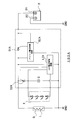
- FIG. 1 is a diagram illustrating an example of a configuration of a vehicle LED lamp lighting circuit 100 according to a first embodiment which is an aspect of the present invention.
- FIG. 2 is a diagram showing an example of the configuration of a conventional LED lamp lighting circuit 100A.
- the vehicle LED lamp lighting circuit 100 controls lighting of an LED lamp X mounted on a vehicle (not shown) such as a two-wheeled vehicle using an AC voltage generated by a single-phase AC generator G. (Fig. 1).
- the vehicle LED lamp lighting circuit 100 is mounted on, for example, the vehicle described above.
- the single-phase AC generator G includes a coil L having one end connected to the first generator terminal TG1 and the other end connected to the second generator terminal TG2.
- the other end of the coil L is also connected to the ground line GND.
- the ground line GND is grounded.
- the ground potential is not limited to 0 V, and is set to a fixed potential lower than the power supply voltage so that at least the LED lamp can be lit.
- the single-phase AC generator G charges the battery B, generates an AC voltage for lighting the LED lamp X, and outputs the AC voltage from both ends of the coil L.
- This single-phase AC generator G is an alternator that is directly driven by an engine of a vehicle such as a motorcycle. Moreover, this single-phase alternating current generator G may be driven by a user's kick drive.
- the single-phase AC generator G and the vehicle LED lamp lighting circuit 100 constitute a vehicle LED lamp lighting device according to this embodiment.
- the vehicle LED lamp lighting circuit 100 includes, for example, an LED lamp X having one end connected to the first generator terminal TG1, a battery B having a negative electrode B2 connected to the ground line GND, and an LED lamp X having one end connected to the ground line GND. And a switch device SW having one end connected to the positive electrode B1 of the battery B (FIG. 1).
- the vehicle LED lamp lighting circuit 100 includes a second resistor R2 having one end connected to the other end of the switch device SW and the other end connected to the reference node NB, and one end connected to the second generator terminal TG2.
- a rectifying element D connected to the ground line GND and having the other end connected to the reference node NB.
- the vehicle LED lamp lighting circuit 100 has a first switch element S1 having one end connected to the first generator terminal TG1 and the other end connected to the positive electrode B1 of the battery B (first battery terminal TB1). And a battery voltage control circuit BZ for controlling the first switch element S1 based on the voltage of the first generator terminal TG1 and the voltage of the positive electrode B1 of the battery B (first battery terminal TB1).
- the vehicle LED lamp lighting circuit 100 has one end connected to the reference node NB and the other end connected to the other end (LED terminal TX) of the first resistor R1, and one end connected to the second switch element S2.
- the LED lamp X includes at least one LED element A.
- FIG. 1 a configuration example of an LED lamp X in which four LED elements A are connected in series is shown.
- One end of the LED lamp X is connected to the anode side of the LED element A, and the other end of the LED lamp X is connected to the cathode side of the LED element A (FIG. 1).
- the LED lamp X is, for example, any one of the above-described two-wheeled vehicle headlight, turn signal, tail lamp, position lamp, and meter illumination.
- Battery B has positive electrode B1 connected to first battery terminal TB1, and negative electrode B2 connected to ground line GND.
- This battery B is, for example, the battery of the motorcycle described above.
- the first resistor R1 has one end connected to the other end of the LED lamp X and the other end connected to the LED terminal TX.
- the first resistor R1 limits the current flowing through the LED element A.
- one end of the switch device SW is connected to the positive electrode B1 (first battery terminal TB1) of the battery B, and the other end is connected to the second battery terminal TB2.
- the switch device SW is turned on or off by the user, for example.
- the switch device SW is, for example, an ignition switch for controlling ignition of the engine of the two-wheeled vehicle described above.
- the switch device SW when the switch device SW is turned on by the user operating the switch device SW, the engine described above is ignited and driven, whereby the single-phase AC generator G starts generating power and the coil L AC voltage is output from
- one end of the second resistor R2 is connected to the other end (second battery terminal TB2) of the switch device SW, and the other end is connected to the reference node NB.
- the rectifying element D has one end connected to the second generator terminal TG2 and the ground line GND, and the other end connected to the reference node NB.
- the rectifying element D has a forward direction from the second generator terminal TG2 toward the reference node NB.
- the rectifying element D is a diode having a cathode connected to the reference node NB and an anode connected to the second generator terminal TG2 (FIG. 1).
- the first switch element S1 has one end connected to the first generator terminal TG1 and the other end connected to the positive electrode B1 of the battery B (first battery terminal TB1).
- the first switch element S1 has a cathode connected to the positive electrode B1 (first battery terminal TB1) of the battery B, an anode connected to the first generator terminal TG1, and is gated by the battery voltage control circuit BZ. 1 is a first thyristor in which the current flowing through the first is controlled (FIG. 1). The first thyristor is controlled to be turned on / off by the current flowing through the gate.
- the battery voltage control circuit BZ controls the first switch element S1 based on the voltage of the first generator terminal TG1 and the voltage of the positive electrode B1 of the battery B.
- the output voltage of the first generator terminal TG1 output from the single-phase AC generator G is equal to or higher than the positive specified voltage, and the charging voltage of the positive electrode B1 of the battery B is less than the target voltage.
- the first switch element S1 is turned on. Thereby, the charging current is supplied from the single-phase AC generator G to the battery B.
- the battery B is connected so that the charging voltage of the battery B approaches the target voltage. Charged.
- the battery voltage control circuit BZ is used when the output voltage of the first generator terminal TG1 output from the single-phase AC generator G is less than a positive specified voltage or a negative voltage, or when the positive voltage B1 of the battery B is When the charging voltage is equal to or higher than the target voltage described above, the first switch element S1 is turned off. Thereby, the supply of the charging current from the single-phase AC generator G to the battery B is stopped.
- the second switch element S2 has one end connected to the reference node NB and the other end connected to the other end (LED terminal TX) of the first resistor R1.
- a cathode is connected to the other end of the first resistor R1
- an anode is connected to the reference node NB
- a current flowing through the gate is controlled by the LED voltage control circuit LZ. (Fig. 1).
- the second thyristor is controlled to be turned on / off by the current flowing through the gate.
- the capacitor C has one end connected to the first generator terminal TG1 and the other end connected to the other end of the first resistor R1.
- the voltage charged in the capacitor C is applied to the LED lamp X.
- the LED voltage control circuit LZ controls the second switch element S2 so that the potential difference between the first generator terminal TG1 and the second generator terminal TG2 becomes a preset specified value.
- the LED voltage control circuit LZ controls the second switch element S2 so that the voltage of the capacitor C becomes a preset value.
- the LED voltage control circuit LZ turns on the second switch element S2 when the potential difference between the first generator terminal TG1 and the second generator terminal TG2 is less than a specified value.
- the LED voltage control circuit LZ turns off the second switch element S2 when the potential difference between the first generator terminal TG1 and the second generator terminal TG2 is equal to or greater than the specified value described above. To do.
- the voltage supplied to the LED lamp X is controlled to a predetermined value.
- the switch device SW when the switch device SW is operated by the user, the switch device SW is turned on.
- the LED voltage control circuit LZ turns on the second switch element S2 when the potential difference between the first generator terminal TG1 and the second generator terminal TG2 is less than the specified value.
- the LED lamp X can be lit more reliably in a state where the single-phase AC generator G is not generating power (the engine is not started).
- the LED voltage control circuit LZ turns on the second switch element S2 when the potential difference between the first generator terminal TG1 and the second generator terminal TG2 is less than a specified value.
- the current supplied to the LED lamp X and the capacitor C is supplied from the single-phase AC generator G compared to the supply current to the LED lamp X when the single-phase AC generator G is stopped.
- the current increases.
- the potential of the reference node NB is lower than the ground potential by the forward voltage of the diode D, for example, about ⁇ 1 V, and is stable. ing.
- the potential of the reference node NB is changed from the voltage of the positive electrode B1 of the battery B (for example, 14V) to the voltage drop of the second resistor R2 ( For example, it is lower by 15V), for example, about -1V.
- the LED voltage control circuit LZ turns off the second switch element S2 when the potential difference between the first generator terminal TG1 and the second generator terminal TG2 is equal to or greater than the specified value described above. To do.
- the voltage supplied to the LED lamp X is controlled to a predetermined value by controlling the voltage of the capacitor C to a preset value.
- the switch device SW After the switch device SW is turned on by the user operating the switch device SW, the engine described above is ignited and driven, whereby the single-phase AC generator G starts generating power and the coil
- the single-phase AC generator G starts generating power and outputs an AC voltage from the coil L by the user's kick drive. The same will be explained.
- the vehicle LED lamp lighting circuit is a vehicle LED lamp lighting circuit that controls lighting of an LED lamp mounted on a vehicle, and includes at least one LED element.
- An LED lamp connected to a first generator terminal to which one end of a coil L of a single-phase AC generator is connected, and a battery having a negative electrode connected to a grounded ground line.
- a first resistor whose one end is connected to the other end of the LED lamp, one end connected to the positive electrode of the battery, and is turned on to conduct between the one end and the other end;
- a switch device that cuts off between the second resistor, one end connected to the other end of the switch device, the other end connected to the reference node, and one end to the other end of the coil L of the single-phase AC generator Second generator terminal connected to A rectifying element in which the direction from the second generator terminal toward the reference node is a forward direction, and one end is connected to the first generator terminal.
- a first switch element having the other end connected to the positive electrode of the battery, a voltage of the first generator terminal, and a battery voltage control circuit that controls the first switch element based on the voltage of the positive electrode of the battery;
- a second switch element having one end connected to the reference node and the other end connected to the other end of the first resistor, one end connected to the first generator terminal, and the other end connected to the first resistor LED voltage control circuit for controlling the second switch element so that the potential difference between the capacitor connected to the end and the first generator terminal and the second generator terminal becomes a preset specified value And comprising.
- this vehicle LED lamp lighting circuit when a switch device (ignition switch device) is turned on by a user, the switch device, the second resistor, the reference node, the second switch element, and the second generator are turned on from the battery. A current is supplied to the LED lamp via the terminal and the first resistor.
- a switch device ignition switch device
- the LED voltage control circuit LZ includes the second switch element so that the potential difference (capacitor voltage) between the first generator terminal and the second generator terminal becomes a preset specified value. To control.
- the LED lamp can be lit more reliably in a state where the single-phase AC generator is not generating power (the engine is not started).
- the first resistor limits the current supplied to the LED lamp, the current consumption can be reduced. Furthermore, since the second resistor limits the current output from the battery, it is possible to reduce current consumption when the single-phase AC generator is not generating power.
- the single-phase AC generator starts generating power and outputs an AC voltage from the coil L.
- the LED lamp is lit mainly by the current output from the battery.
- the coil L of the single-phase AC generator is passed through the rectifier element, the reference node, the second switch element, the second generator terminal, and the first resistor.
- the LED lamp is additionally supplied with current.
- the LED voltage control circuit LZ has the second switch so that the potential difference (capacitor voltage) between the first generator terminal and the second generator terminal becomes a preset specified value. Control the element. Thereby, after a single phase alternating current generator starts electric power generation, the brightness of an LED lamp can be raised.
- the LED lamp can be more reliably lit in a state where the single-phase AC generator is not generating power or in a state where the output of the single-phase AC generator is low. it can.
Landscapes
- Engineering & Computer Science (AREA)
- Mechanical Engineering (AREA)
- Circuit Arrangement For Electric Light Sources In General (AREA)
- Lighting Device Outwards From Vehicle And Optical Signal (AREA)
Abstract
LEDランプ点灯回路は、車両に積載されるLEDランプの点灯を制御する車両用LEDランプ点灯回路であって、第1の発電機端子の電圧、及びバッテリの正極の電圧に基づいて、第1のスイッチ素子を制御するバッテリ電圧制御回路と、第1の発電機端子と第2の発電機端子との間の電位差が予め設定された規定値になるように、第2のスイッチ素子を制御するLED電圧制御回路と、を備える。
Description
本発明は、車両用LEDランプ点灯回路、車両用LEDランプ点灯装置、および車両用LEDランプ点灯回路の制御方法に関する。
従来、フィラメント灯(バルブランプ)の点灯を制御するランプ点灯装置がある。この従来のランプ点灯装置には、例えば、発電機で発電した電力をフィラメント灯(バルブランプ)に供給して点灯させるとともに、バッテリを充電するものがある(例えば、特開平01-160329号参照)。
一方、LED(Light Emitting Diode) ランプは、低電圧で駆動することができ、フィラメント灯(バルブランプ)などと比較して長寿命、低消費電力、素早い反応速度、及び耐衝撃性を有しており、小型、軽量化を図ることができる。
このため、LEDランプは、例えば、車両のヘッドランプなどに好適に用いることができる。
このような、LEDランプの点灯を制御するLEDランプ点灯装置の一例として、単相交流発電機で発電した電力でバッテリを充電するとともに、単相交流発電機で発電した電力でLEDランプを点灯させるLEDランプ点灯回路100Aがある(図2)。
このLEDランプ点灯回路100Aは、LEDランプXと、接地線GNDに負極が接続されたバッテリBと、アノードが単相交流発電機GのコイルLの一端に接続され、カソードがバッテリBの正極に接続された第1のサイリスタS1Aと、単相交流発電機Gの出力電圧及びバッテリBの正極の電圧に基づいて、第1のサイリスタS1Aを制御するバッテリ電圧制御回路BZAと、カソードがコイルLの一端に接続された第2のサイリスタS2Aと、一端が第2のサイリスタS2Aに接続され、他端がコイルLの他端に接続されたキャパシタCと、出力電圧に基づいて第2のサイリスタS2Aを制御するLED電圧制御回路LZAと、を備える(図2)。
ここで、既述の従来の車両用LEDランプ点灯回路100Aでは、単相交流発電機Gで発電した電力でLEDランプXを点灯させるため、単相交流発電機Gが発電していない状態若しくは単相交流発電機Gの出力が低い状態で、LEDランプXを点灯することができない問題がある。
そこで、本発明は、単相交流発電機が発電していない状態若しくは単相交流発電機の出力が低い状態で、LEDランプをより確実に点灯することが可能な車両用LEDランプ点灯回路を提供することを目的とする。
本発明の一態様に係る実施形態に従ったLEDランプ点灯回路は、
車両に積載されるLEDランプの点灯を制御する車両用LEDランプ点灯回路であって、
少なくとも1つ以上のLED素子を有し、一端が、単相交流発電機のコイルの一端が接続されている第1の発電機端子に、接続されたLEDランプと、
接地された接地線に、負極が接続されたバッテリと、
一端が前記LEDランプの他端に接続される第1の抵抗と、
一端が前記バッテリの正極に接続され、オンすることにより一端と他端との間を導通し、オフすることにより一端と他端との間を遮断するスイッチ装置と、
一端が前記スイッチ装置の他端に接続され、他端が基準ノードに接続された第2の抵抗と、
一端が、前記単相交流発電機の前記コイルの他端に接続されている第2の発電機端子及び前記接地線に、接続され、他端が前記基準ノードに接続され、前記第2の発電機端子から前記基準ノードに向かう方向が順方向となる整流素子と、
一端が前記第1の発電機端子に接続され、他端が前記バッテリの正極に接続された第1のスイッチ素子と、
前記第1の発電機端子の電圧、及び前記バッテリの正極の電圧に基づいて、前記第1のスイッチ素子を制御するバッテリ電圧制御回路と、
一端が前記基準ノードに接続され、他端が前記第1の抵抗の他端に接続された第2のスイッチ素子と、
一端が前記第1の発電機端子に接続され、他端が前記第1の抵抗の他端に接続されたキャパシタと、
前記第1の発電機端子と前記第2の発電機端子との間の電位差が予め設定された規定値になるように、前記第2のスイッチ素子を制御するLED電圧制御回路と、を備える
ことを特徴とする。
車両に積載されるLEDランプの点灯を制御する車両用LEDランプ点灯回路であって、
少なくとも1つ以上のLED素子を有し、一端が、単相交流発電機のコイルの一端が接続されている第1の発電機端子に、接続されたLEDランプと、
接地された接地線に、負極が接続されたバッテリと、
一端が前記LEDランプの他端に接続される第1の抵抗と、
一端が前記バッテリの正極に接続され、オンすることにより一端と他端との間を導通し、オフすることにより一端と他端との間を遮断するスイッチ装置と、
一端が前記スイッチ装置の他端に接続され、他端が基準ノードに接続された第2の抵抗と、
一端が、前記単相交流発電機の前記コイルの他端に接続されている第2の発電機端子及び前記接地線に、接続され、他端が前記基準ノードに接続され、前記第2の発電機端子から前記基準ノードに向かう方向が順方向となる整流素子と、
一端が前記第1の発電機端子に接続され、他端が前記バッテリの正極に接続された第1のスイッチ素子と、
前記第1の発電機端子の電圧、及び前記バッテリの正極の電圧に基づいて、前記第1のスイッチ素子を制御するバッテリ電圧制御回路と、
一端が前記基準ノードに接続され、他端が前記第1の抵抗の他端に接続された第2のスイッチ素子と、
一端が前記第1の発電機端子に接続され、他端が前記第1の抵抗の他端に接続されたキャパシタと、
前記第1の発電機端子と前記第2の発電機端子との間の電位差が予め設定された規定値になるように、前記第2のスイッチ素子を制御するLED電圧制御回路と、を備える
ことを特徴とする。
前記LEDランプ点灯回路において、
前記スイッチ装置がオンした後、前記単相交流発電機が発電を開始して前記コイルから交流電圧を出力する
ことを特徴とする。
前記スイッチ装置がオンした後、前記単相交流発電機が発電を開始して前記コイルから交流電圧を出力する
ことを特徴とする。
前記LEDランプ点灯回路において、
前記第2のスイッチ素子は、
前記第1の抵抗の他端にカソードが接続され、前記基準ノードにアノードが接続され、前記LED電圧制御回路によりゲートに流れる電流が制御される第2のサイリスタである
ことを特徴とする。
前記第2のスイッチ素子は、
前記第1の抵抗の他端にカソードが接続され、前記基準ノードにアノードが接続され、前記LED電圧制御回路によりゲートに流れる電流が制御される第2のサイリスタである
ことを特徴とする。
前記LEDランプ点灯回路において、
前記LED電圧制御回路は、
前記第1の発電機端子と前記第2の発電機端子との間の電位差が前記規定値未満である場合には、前記第2のスイッチ素子をオンし、
前記第1の発電機端子と前記第2の発電機端子との間の電位差が前記規定値以上である場合には、前記第2のスイッチ素子をオフする
ことを特徴とする。
前記LED電圧制御回路は、
前記第1の発電機端子と前記第2の発電機端子との間の電位差が前記規定値未満である場合には、前記第2のスイッチ素子をオンし、
前記第1の発電機端子と前記第2の発電機端子との間の電位差が前記規定値以上である場合には、前記第2のスイッチ素子をオフする
ことを特徴とする。
前記LEDランプ点灯回路において、
前記LED電圧制御回路は、
前記キャパシタの電圧が予め設定された値になるように、前記第2のスイッチ素子を制御する
ことを特徴とする。
前記LED電圧制御回路は、
前記キャパシタの電圧が予め設定された値になるように、前記第2のスイッチ素子を制御する
ことを特徴とする。
前記LEDランプ点灯回路において、
前記第1のスイッチ素子は、
前記バッテリの正極にカソードが接続され、前記第1の発電機端子にアノードが接続され、前記バッテリ電圧制御回路によりゲートに流れる電流が制御される第1のサイリスタである
ことを特徴とする。
前記第1のスイッチ素子は、
前記バッテリの正極にカソードが接続され、前記第1の発電機端子にアノードが接続され、前記バッテリ電圧制御回路によりゲートに流れる電流が制御される第1のサイリスタである
ことを特徴とする。
前記LEDランプ点灯回路において、
前記バッテリ電圧制御回路は、
前記単相交流発電機から出力された前記第1の発電機端子の出力電圧が正の規定電圧以上であり且つ前記バッテリの正極の充電電圧が目標電圧未満の場合に、前記第1のスイッチ素子をオンする
ことを特徴とする。
前記バッテリ電圧制御回路は、
前記単相交流発電機から出力された前記第1の発電機端子の出力電圧が正の規定電圧以上であり且つ前記バッテリの正極の充電電圧が目標電圧未満の場合に、前記第1のスイッチ素子をオンする
ことを特徴とする。
前記LEDランプ点灯回路において、
前記バッテリ電圧制御回路は、
前記単相交流発電機から出力された前記第1の発電機端子の前記出力電圧が正の規定電圧未満若しくは負の電圧である場合、又は前記バッテリの正極の充電電圧が前記目標電圧以上の場合に、前記第1のスイッチ素子をオフする
ことを特徴とする。
前記バッテリ電圧制御回路は、
前記単相交流発電機から出力された前記第1の発電機端子の前記出力電圧が正の規定電圧未満若しくは負の電圧である場合、又は前記バッテリの正極の充電電圧が前記目標電圧以上の場合に、前記第1のスイッチ素子をオフする
ことを特徴とする。
前記LEDランプ点灯回路において、
前記スイッチ装置は、ユーザによりオン又はオフに操作されることを特徴とする。
前記スイッチ装置は、ユーザによりオン又はオフに操作されることを特徴とする。
前記LEDランプ点灯回路において、
前記車両用LEDランプ点灯回路は、二輪車に積載され、前記LEDランプは、前記二輪車のヘッドライト、ウインカー、テールランプ、ポジションランプ、メータイルミネーションの何れかである
ことを特徴とする。
前記車両用LEDランプ点灯回路は、二輪車に積載され、前記LEDランプは、前記二輪車のヘッドライト、ウインカー、テールランプ、ポジションランプ、メータイルミネーションの何れかである
ことを特徴とする。
前記LEDランプ点灯回路において、
前記単相交流発電機は、
前記二輪車のエンジンに接続されたオルタネータであり、
前記スイッチ装置は、
前記二輪車の前記エンジンの点火を制御するためのイグニッションスイッチである
ことを特徴とする。
前記単相交流発電機は、
前記二輪車のエンジンに接続されたオルタネータであり、
前記スイッチ装置は、
前記二輪車の前記エンジンの点火を制御するためのイグニッションスイッチである
ことを特徴とする。
前記LEDランプ点灯回路において、
前記整流素子は、
カソードが前記基準ノードに接続され、アノードが前記第2の発電機端子に接続されたダイオードである
ことを特徴とする。
前記整流素子は、
カソードが前記基準ノードに接続され、アノードが前記第2の発電機端子に接続されたダイオードである
ことを特徴とする。
前記LEDランプ点灯回路において、
前記LEDランプの前記一端は、前記LED素子のアノード側が接続され、前記LEDランプの前記他端は、前記LED素子のカソード側が接続されている
ことを特徴とする。
前記LEDランプの前記一端は、前記LED素子のアノード側が接続され、前記LEDランプの前記他端は、前記LED素子のカソード側が接続されている
ことを特徴とする。
本発明の一態様に係る実施形態に従ったLEDランプ点灯装置は、
車両に積載されるLED素子の点灯を制御する車両用LEDランプ点灯装置であって、
単相交流発電機と、
少なくとも1つ以上のLED素子を有し、一端が、前記単相交流発電機のコイルの一端が接続されている第1の発電機端子に、接続されたLEDランプと、
接地された接地線に、負極が接続されたバッテリと、
一端が前記LEDランプの他端に接続される第1の抵抗と、
一端が前記バッテリの正極に接続され、オンすることにより一端と他端との間を導通し、オフすることにより一端と他端との間を遮断するスイッチ装置と、
一端が前記スイッチ装置の他端に接続され、他端が基準ノードに接続された第2の抵抗と、
一端が、前記単相交流発電機の前記コイルの他端に接続されている第2の発電機端子及び前記接地線に、接続され、他端が前記基準ノードに接続され、前記第2の発電機端子から前記基準ノードに向かう方向が順方向となる整流素子と、
一端が前記第1の発電機端子に接続され、他端が前記バッテリの正極に接続された第1のスイッチ素子と、
前記第1の発電機端子の電圧、及び前記バッテリの正極の電圧に基づいて、前記第1のスイッチ素子を制御するバッテリ電圧制御回路と、
一端が前記基準ノードに接続され、他端が前記第1の抵抗の他端に接続された第2のスイッチ素子と、
一端が前記第1の発電機端子に接続され、他端が前記第1の抵抗の他端に接続されたキャパシタと、
前記第1の発電機端子と前記第2の発電機端子との間の電位差が予め設定された規定値になるように、前記第2のスイッチ素子を制御するLED電圧制御回路と、を備える
ことを特徴とする。
車両に積載されるLED素子の点灯を制御する車両用LEDランプ点灯装置であって、
単相交流発電機と、
少なくとも1つ以上のLED素子を有し、一端が、前記単相交流発電機のコイルの一端が接続されている第1の発電機端子に、接続されたLEDランプと、
接地された接地線に、負極が接続されたバッテリと、
一端が前記LEDランプの他端に接続される第1の抵抗と、
一端が前記バッテリの正極に接続され、オンすることにより一端と他端との間を導通し、オフすることにより一端と他端との間を遮断するスイッチ装置と、
一端が前記スイッチ装置の他端に接続され、他端が基準ノードに接続された第2の抵抗と、
一端が、前記単相交流発電機の前記コイルの他端に接続されている第2の発電機端子及び前記接地線に、接続され、他端が前記基準ノードに接続され、前記第2の発電機端子から前記基準ノードに向かう方向が順方向となる整流素子と、
一端が前記第1の発電機端子に接続され、他端が前記バッテリの正極に接続された第1のスイッチ素子と、
前記第1の発電機端子の電圧、及び前記バッテリの正極の電圧に基づいて、前記第1のスイッチ素子を制御するバッテリ電圧制御回路と、
一端が前記基準ノードに接続され、他端が前記第1の抵抗の他端に接続された第2のスイッチ素子と、
一端が前記第1の発電機端子に接続され、他端が前記第1の抵抗の他端に接続されたキャパシタと、
前記第1の発電機端子と前記第2の発電機端子との間の電位差が予め設定された規定値になるように、前記第2のスイッチ素子を制御するLED電圧制御回路と、を備える
ことを特徴とする。
本発明の一態様に係る実施形態に従ったLEDランプ点灯回路の制御方法は、車両に積載されるLEDランプの点灯を制御する車両用LEDランプ点灯回路であって、少なくとも1つ以上のLED素子を有し、一端が、単相交流発電機のコイルの一端が接続されている第1の発電機端子に、接続されたLEDランプと、接地された接地線に、負極が接続されたバッテリと、一端が前記LEDランプの他端に接続される第1の抵抗と、一端が前記バッテリの正極に接続され、オンすることにより一端と他端との間を導通し、オフすることにより一端と他端との間を遮断するスイッチ装置と、一端が前記スイッチ装置の他端に接続され、他端が基準ノードに接続された第2の抵抗と、一端が、前記単相交流発電機の前記コイルの他端に接続されている第2の発電機端子及び前記接地線に、接続され、他端が前記基準ノードに接続され、前記第2の発電機端子から前記基準ノードに向かう方向が順方向となる整流素子と、一端が前記第1の発電機端子に接続され、他端が前記バッテリの正極に接続された第1のスイッチ素子と、前記第1の発電機端子の電圧、及び前記バッテリの正極の電圧に基づいて、前記第1のスイッチ素子を制御するバッテリ電圧制御回路と、一端が前記基準ノードに接続され、他端が前記第1の抵抗の他端に接続された第2のスイッチ素子と、一端が前記第1の発電機端子に接続され、他端が前記第1の抵抗の他端に接続されたキャパシタと、前記第1の発電機端子と前記第2の発電機端子との間の電位差が予め設定された規定値になるように、前記第2のスイッチ素子を制御するLED電圧制御回路と、を備える車両用LEDランプ点灯回路の制御方法であって、
前記スイッチ装置がオンした後、前記単相交流発電機が発電を開始して前記コイルから交流電圧を出力し、
前記第1の発電機端子と前記第2の発電機端子との間の電位差が前記規定値未満である場合には、前記第2のスイッチ素子をオンし、
前記第1の発電機端子と前記第2の発電機端子との間の電位差が前記規定値以上である場合には、前記第2のスイッチ素子をオフする
ことを特徴とする。
前記スイッチ装置がオンした後、前記単相交流発電機が発電を開始して前記コイルから交流電圧を出力し、
前記第1の発電機端子と前記第2の発電機端子との間の電位差が前記規定値未満である場合には、前記第2のスイッチ素子をオンし、
前記第1の発電機端子と前記第2の発電機端子との間の電位差が前記規定値以上である場合には、前記第2のスイッチ素子をオフする
ことを特徴とする。
本発明の一態様に係る車両用LEDランプ点灯回路は、車両に積載されるLEDランプの点灯を制御する車両用LEDランプ点灯回路であって、少なくとも1つ以上のLED素子を有し、一端が、単相交流発電機のコイルの一端が接続されている第1の発電機端子に、接続されたLEDランプと、接地された接地線に、負極が接続されたバッテリと、一端が前記LEDランプの他端に接続される第1の抵抗と、一端が前記バッテリの正極に接続され、オンすることにより一端と他端との間を導通し、オフすることにより一端と他端との間を遮断するスイッチ装置と、一端が前記スイッチ装置の他端に接続され、他端が基準ノードに接続された第2の抵抗と、一端が、前記単相交流発電機の前記コイルの他端に接続されている第2の発電機端子及び前記接地線に、接続され、他端が前記基準ノードに接続され、前記第2の発電機端子から前記基準ノードに向かう方向が順方向となる整流素子と、一端が前記第1の発電機端子に接続され、他端が前記バッテリの正極に接続された第1のスイッチ素子と、前記第1の発電機端子の電圧、及び前記バッテリの正極の電圧に基づいて、前記第1のスイッチ素子を制御するバッテリ電圧制御回路と、一端が前記基準ノードに接続され、他端が前記第1の抵抗の他端に接続された第2のスイッチ素子と、一端が前記第1の発電機端子に接続され、他端が前記第1の抵抗の他端に接続されたキャパシタと、前記第1の発電機端子と前記第2の発電機端子との間の電位差が予め設定された規定値になるように、前記第2のスイッチ素子を制御するLED電圧制御回路と、を備える。
この車両用LEDランプ点灯回路において、スイッチ装置(イグニッションスイッチ装置)がユーザにより、オンされると、バッテリから、スイッチ装置、第2の抵抗、基準ノード、第2のスイッチ素子、第2の発電機端子、及び第1の抵抗を介して、LEDランプに電流が供給される。
このとき、LED電圧制御回路は、第1の発電機端子と第2の発電機端子との間の電位差(キャパシタの電圧)が予め設定された規定値になるように、第2のスイッチ素子を制御する。
これにより、LEDランプに点灯するための所定の電流および所定の電圧が供給される。
すなわち、単相交流発電機が発電していない(エンジンが始動していない)状態で、LEDランプをより確実に点灯することができる。
なお、第1の抵抗が、LEDランプに供給される電流を制限するので、消費電流を低減することができる。さらに、第2の抵抗が、バッテリから出力される電流を制限するので、単相交流発電機が発電していない状態における消費電流を低減することができる。
そして、スイッチ装置がオンした後、単相交流発電機が発電を開始してコイルから交流電圧を出力する。単相交流発電機の出力が低い状態では、主としてバッテリから出力される電流により、LEDランプが点灯する。
さらに、単相交流発電機の出力が高くなると、単相交流発電機のコイルから、整流素子、基準ノード、第2のスイッチ素子、第2の発電機端子、及び第1の抵抗を介して、LEDランプに電流が追加で供給される。
このときも、LED電圧制御回路は、第1の発電機端子と第2の発電機端子との間の電位差(キャパシタの電圧)が予め設定された規定値になるように、第2のスイッチ素子を制御する。これにより、単相交流発電機が発電を開始した後は、LEDランプの明るさを上昇させることができる。
したがって、本発明に係る車両用LEDランプ点灯回路によれば、単相交流発電機が発電していない状態若しくは単相交流発電機の出力が低い状態で、LEDランプをより確実に点灯することができる。
以下、本発明に係る実施形態について図面に基づいて説明する。
本実施形態に係る車両用LEDランプ点灯回路100は、単相交流発電機Gで発電した交流電圧を用いて、二輪車等の車両(図示せず)に積載されるLEDランプXの点灯を制御するようになっている(図1)。この車両用LEDランプ点灯回路100は、例えば、既述の車両に積載される。
単相交流発電機Gは、一端が第1の発電機端子TG1に接続され、他端が第2の発電機端子TG2に接続されたコイルLを、有する。このコイルLの他端は、接地線GNDにも接続されている。なお、接地線GNDは、接地されている。この接地の電位は、0Vに限定されるものではなく、少なくともLEDランプを点灯可能なように、電源電圧より低い固定の電位に設定される。
また、単相交流発電機Gは、バッテリBを充電するとともにLEDランプXを点灯するための交流電圧を発生し、コイルLの両端から出力するようになっている。
この単相交流発電機Gは、例えば、二輪車等の車両のエンジンにより直結駆動されるオルタネータである。また、この単相交流発電機Gは、ユーザのキック駆動により、駆動される場合もある。
なお、この単相交流発電機Gと車両用LEDランプ点灯回路100とは、本実施形態に係る車両用LEDランプ点灯装置を構成する。
また、車両用LEDランプ点灯回路100は、例えば、一端が第1の発電機端子TG1に接続されたLEDランプXと、接地線GNDに負極B2が接続されたバッテリBと、一端がLEDランプXの他端に接続される第1の抵抗R1と、一端がバッテリBの正極B1に接続されたスイッチ装置SWと、を備える(図1)。
さらに、車両用LEDランプ点灯回路100は、一端がスイッチ装置SWの他端に接続され、他端が基準ノードNBに接続された第2の抵抗R2と、一端が第2の発電機端子TG2及び接地線GNDに接続され、他端が基準ノードNBに接続された整流素子Dと、を備える。
さらに、車両用LEDランプ点灯回路100は、一端が第1の発電機端子TG1に接続され、他端がバッテリBの正極B1(第1のバッテリ端子TB1)に接続された第1のスイッチ素子S1と、第1の発電機端子TG1の電圧及びバッテリBの正極B1(第1のバッテリ端子TB1)の電圧に基づいて、第1のスイッチ素子S1を制御するバッテリ電圧制御回路BZと、を備える。
さらに、車両用LEDランプ点灯回路100は、一端が基準ノードNBに接続され、他端が第1の抵抗R1の他端(LED端子TX)に接続された第2のスイッチ素子S2と、一端が第1の発電機端子TG1に接続され、他端が第1の抵抗R1の他端に接続されたキャパシタCと、第1の発電機端子TG1と第2の発電機端子TG2との間の電位差が予め設定された規定値になるように、第2のスイッチ素子S2を制御するLED電圧制御回路LZと、を備える。
ここで、LEDランプXは、既述のように、一端が第1の発電機端子TG1に接続されている。このLEDランプXは、少なくとも1つ以上のLED素子Aを有する。なお、図1の例では、4つのLED素子Aが直列に接続されたLEDランプXの構成例を示している。
このLEDランプXの一端は、LED素子Aのアノード側が接続され、LEDランプXの他端は、LED素子Aのカソード側が接続されている(図1)。
このLEDランプXは、例えば、既述の二輪車のヘッドライト、ウインカー、テールランプ、ポジションランプ、メータイルミネーションの何れかである。
バッテリBは、正極B1が第1のバッテリ端子TB1に接続され、負極B2が接地線GNDに接続されている。このバッテリBは、例えば、既述の二輪車のバッテリである。
また、第1の抵抗R1は、一端がLEDランプXの他端に接続され、他端がLED端子TXに接続されている。
この第1の抵抗R1は、LED素子Aに流れる電流を制限するようになっている。
また、スイッチ装置SWは、既述のように、一端がバッテリBの正極B1(第1のバッテリ端子TB1)に接続され、他端が第2のバッテリ端子TB2に接続されている。
このスイッチ装置SWがオンすることにより一端と他端との間を導通し、オフすることにより一端と他端との間を遮断する。
このスイッチ装置SWは、例えば、ユーザによりオン又はオフに操作される。このスイッチ装置SWは、例えば、既述の二輪車のエンジンの点火を制御するためのイグニッションスイッチである。
そして、例えば、スイッチ装置SWがユーザにより操作されることにより、このスイッチ装置SWがオンした後、既述のエンジンが点火され駆動することにより単相交流発電機Gが発電を開始してコイルLから交流電圧を出力する。
また、第2の抵抗R2は、一端がスイッチ装置SWの他端(第2のバッテリ端子TB2)に接続され、他端が基準ノードNBに接続されている。
また、整流素子Dは、一端が第2の発電機端子TG2及び接地線GNDに接続され、他端が基準ノードNBに接続されている。この整流素子Dは、第2の発電機端子TG2から基準ノードNBに向かう方向が順方向となる。
例えば、この整流素子Dは、カソードが基準ノードNBに接続され、アノードが第2の発電機端子TG2に接続されたダイオードである(図1)。
第1のスイッチ素子S1は、一端が第1の発電機端子TG1に接続され、他端がバッテリBの正極B1(第1のバッテリ端子TB1)に接続されている。
この第1のスイッチ素子S1は、例えば、バッテリBの正極B1(第1のバッテリ端子TB1)にカソードが接続され、第1の発電機端子TG1にアノードが接続され、バッテリ電圧制御回路BZによりゲートに流れる電流が制御される第1のサイリスタである(図1)。この第1のサイリスタは、このゲートに流れる電流により、オン/オフが制御される。
また、バッテリ電圧制御回路BZは、第1の発電機端子TG1の電圧及びバッテリBの正極B1の電圧に基づいて、第1のスイッチ素子S1を制御する。
例えば、バッテリ電圧制御回路BZは、単相交流発電機Gから出力された第1の発電機端子TG1の出力電圧が正の規定電圧以上であり且つバッテリBの正極B1の充電電圧が目標電圧未満の場合に、第1のスイッチ素子S1をオンする。これにより、単相交流発電機GからバッテリBに充電電流が供給される。
すなわち、単相交流発電機Gの出力電圧が該規定電圧以上であり且つバッテリBの充電電圧が該目標電圧未満のときに、バッテリBの充電電圧が該目標電圧に近づくように、バッテリBが充電される。
一方、バッテリ電圧制御回路BZは、単相交流発電機Gから出力された第1の発電機端子TG1の出力電圧が正の規定電圧未満若しくは負の電圧である場合、又はバッテリBの正極B1の充電電圧が既述の目標電圧以上の場合に、第1のスイッチ素子S1をオフする。これにより、単相交流発電機GからバッテリBへの充電電流の供給が停止する。
すなわち、単相交流発電機Gの出力電圧が正の規定電圧未満若しくは負の電圧であるとき、又はバッテリBの充電電圧が該目標電圧以上のときには、バッテリBの充電が停止される。
また、第2のスイッチ素子S2は、一端が基準ノードNBに接続され、他端が第1の抵抗R1の他端(LED端子TX)に接続されている。
この第2のスイッチ素子S2は、例えば、第1の抵抗R1の他端にカソードが接続され、基準ノードNBにアノードが接続され、LED電圧制御回路LZによりゲートに流れる電流が制御される第2のサイリスタである(図1)。この第2のサイリスタは、このゲートに流れる電流により、オン/オフが制御される。
また、キャパシタCは、一端が第1の発電機端子TG1に接続され、他端が第1の抵抗R1の他端に接続されている。このキャパシタCに充電される電圧が、LEDランプXに印加される。
LED電圧制御回路LZは、第1の発電機端子TG1と第2の発電機端子TG2との間の電位差が予め設定された規定値になるように、第2のスイッチ素子S2を制御する。
特に、LED電圧制御回路LZは、キャパシタCの電圧が予め設定された値になるように、第2のスイッチ素子S2を制御する。
例えば、LED電圧制御回路LZは、第1の発電機端子TG1と第2の発電機端子TG2との間の電位差が規定値未満である場合には、第2のスイッチ素子S2をオンする。
これにより、単相交流発電機Gの出力電圧が負の極性のときに、キャパシタCの電圧が予め設定された値に近づくように、キャパシタCに電流が供給されて、キャパシタCが充電される。
一方、LED電圧制御回路LZは、第1の発電機端子TG1と第2の発電機端子TG2との間の電位差が既述の規定値以上である場合には、第2のスイッチ素子S2をオフする。
これにより、キャパシタCの充電が停止される。
このように、キャパシタCの電圧が予め設定された値に制御されることにより、LEDランプXに供給される電圧が所定値に制御されることになる。
次に、以上のような構成を有するLEDランプ点灯回路100の制御方法の一例について、説明する。なお、スイッチ装置SWがオフのとき、既述のエンジンは、駆動しておらず、単相交流発電機Gは、発電していないものとする。
ここで、例えば、スイッチ装置SWがユーザにより操作されることにより、スイッチ装置SWがオンする。
このスイッチ装置SWがオンすることにより、バッテリBの正極B1と第2のバッテリ端子TB2とが導通して、電気的に接続される。
このとき、LED電圧制御回路LZは、第1の発電機端子TG1と第2の発電機端子TG2との間の電位差が規定値未満である場合には、第2のスイッチ素子S2をオンする。
これにより、バッテリBの正極B1から、スイッチ装置SW、第2の抵抗R2、基準ノードNB、第2のスイッチ素子S2、及び第1の抵抗R1を介して、キャパシタCに電流が供給されてキャパシタCが充電されるとともに、LEDランプXに電流が供給される。
これにより、LEDランプXに点灯するための所定の電流および所定の電圧が供給される。
すなわち、単相交流発電機Gが発電していない(エンジンが始動していない)状態で、LEDランプXをより確実に点灯することができる。
そして、スイッチ装置SWがオンした後、既述のエンジンが点火されて駆動することにより、単相交流発電機Gが発電を開始してコイルLから交流電圧を出力する。
例えば、LED電圧制御回路LZは、第1の発電機端子TG1と第2の発電機端子TG2との間の電位差が規定値未満である場合には、第2のスイッチ素子S2をオンする。
これにより、単相交流発電機Gの出力電圧が負の極性のときは、バッテリBから、基準ノードNBを介して、及び、単相交流発電機Gから、ダイオードD、基準ノードNBを介して、キャパシタCの電圧が予め設定された値に近づくように、キャパシタCに電流が供給されてキャパシタCが充電されるとともに、LEDランプXに電流が供給される。
このとき、LEDランプXとキャパシタCに供給される電流は、単相交流発電機Gが停止している場合にLEDランプXに供給電流と比較して、単相交流発電機Gから供給される電流分だけ、大きくなる。
なお、この単相交流発電機Gの出力電圧が負の極性のときは、基準ノードNBの電位は、接地電位から、ダイオードDの順方向電圧だけ低い、例えば、-1V程度になり、安定している。
また、単相交流発電機Gの出力電圧が正の極性のときは、バッテリBから、基準ノードNBを介して、キャパシタCに電流が供給されて、キャパシタCの電圧が予め設定された値に近づくように、キャパシタCが充電されるとともに、LEDランプXに電流が供給されることとなる。
なお、この単相交流発電機Gの出力電圧が正の極性のときは、基準ノードNBの電位は、バッテリBの正極B1の電圧(例えば、14V)から、第2の抵抗R2の電圧降下(例えば、15V)だけ低い、例えば、-1V程度になる。
一方、LED電圧制御回路LZは、第1の発電機端子TG1と第2の発電機端子TG2との間の電位差が既述の規定値以上である場合には、第2のスイッチ素子S2をオフする。
これにより、キャパシタCの充電が停止される。
以上のように、キャパシタCの電圧が予め設定された値に制御されることにより、LEDランプXに供給される電圧が所定値に制御されることになる。
なお、ここでは、スイッチ装置SWがユーザにより操作されることにより、このスイッチ装置SWがオンした後、既述のエンジンが点火され駆動することにより単相交流発電機Gが発電を開始してコイルLから交流電圧を出力する場合について説明した。しかし、スイッチ装置SWがユーザにより操作されることにより、スイッチ装置SWがオンした後、ユーザのキック駆動により、単相交流発電機Gが発電を開始してコイルLから交流電圧を出力する場合も同様に説明される。
以上のように、本発明の一態様に係る車両用LEDランプ点灯回路は、車両に積載されるLEDランプの点灯を制御する車両用LEDランプ点灯回路であって、少なくとも1つ以上のLED素子を有し、一端が、単相交流発電機のコイルLの一端が接続されている第1の発電機端子に、接続されたLEDランプと、接地された接地線に、負極が接続されたバッテリと、一端がLEDランプの他端に接続される第1の抵抗と、一端がバッテリの正極に接続され、オンすることにより一端と他端との間を導通し、オフすることにより一端と他端との間を遮断するスイッチ装置と、一端がスイッチ装置の他端に接続され、他端が基準ノードに接続された第2の抵抗と、一端が、単相交流発電機のコイルLの他端に接続されている第2の発電機端子及び接地線に、接続され、他端が基準ノードに接続され、第2の発電機端子から基準ノードに向かう方向が順方向となる整流素子と、一端が第1の発電機端子に接続され、他端がバッテリの正極に接続された第1のスイッチ素子と、第1の発電機端子の電圧、及びバッテリの正極の電圧に基づいて、第1のスイッチ素子を制御するバッテリ電圧制御回路と、一端が基準ノードに接続され、他端が第1の抵抗の他端に接続された第2のスイッチ素子と、一端が第1の発電機端子に接続され、他端が第1の抵抗の他端に接続されたキャパシタと、第1の発電機端子と第2の発電機端子との間の電位差が予め設定された規定値になるように、第2のスイッチ素子を制御するLED電圧制御回路と、を備える。
この車両用LEDランプ点灯回路において、スイッチ装置(イグニッションスイッチ装置)がユーザにより、オンされると、バッテリから、スイッチ装置、第2の抵抗、基準ノード、第2のスイッチ素子、第2の発電機端子、及び第1の抵抗を介して、LEDランプに電流が供給される。
このとき、LED電圧制御回路LZは、第1の発電機端子と第2の発電機端子との間の電位差(キャパシタの電圧)が予め設定された規定値になるように、第2のスイッチ素子を制御する。
これにより、LEDランプに点灯するための所定の電流および所定の電圧が供給される。
すなわち、単相交流発電機が発電していない(エンジンが始動していない)状態で、LEDランプをより確実に点灯することができる。
なお、第1の抵抗が、LEDランプに供給される電流を制限するので、消費電流を低減することができる。さらに、第2の抵抗が、バッテリから出力される電流を制限するので、単相交流発電機が発電していない状態における消費電流を低減することができる。
そして、スイッチ装置がオンした後、単相交流発電機が発電を開始してコイルLから交流電圧を出力する。単相交流発電機の出力が低い状態では、主としてバッテリから出力される電流により、LEDランプが点灯する。
さらに、単相交流発電機の出力が高くなると、単相交流発電機のコイルLから、整流素子、基準ノード、第2のスイッチ素子、第2の発電機端子、及び第1の抵抗を介して、LEDランプに電流が追加で供給される。
このときも、LED電圧制御回路LZは、第1の発電機端子と第2の発電機端子との間の電位差(キャパシタの電圧)が予め設定された規定値になるように、第2のスイッチ素子を制御する。これにより、単相交流発電機が発電を開始した後は、LEDランプの明るさを上昇させることができる。
したがって、本発明に係る車両用LEDランプ点灯回路によれば、単相交流発電機が発電していない状態若しくは単相交流発電機の出力が低い状態で、LEDランプをより確実に点灯することができる。
本発明のいくつかの実施形態を説明したが、これらの実施形態は、例として提示したものであり、発明の範囲を限定することは意図していない。これら実施形態は、その他の様々な形態で実施されることが可能であり、発明の要旨を逸脱しない範囲で、種々の省略、置き換え、変更を行うことができる。これら実施形態やその変形は、発明の範囲や要旨に含まれると同様に、特許請求の範囲に記載された発明とその均等の範囲に含まれるものである。
Claims (15)
- 車両に積載されるLEDランプの点灯を制御する車両用LEDランプ点灯回路であって、
少なくとも1つ以上のLED素子を有し、一端が、単相交流発電機のコイルの一端が接続されている第1の発電機端子に、接続されたLEDランプと、
接地された接地線に、負極が接続されたバッテリと、
一端が前記LEDランプの他端に接続される第1の抵抗と、
一端が前記バッテリの正極に接続され、オンすることにより一端と他端との間を導通し、オフすることにより一端と他端との間を遮断するスイッチ装置と、
一端が前記スイッチ装置の他端に接続され、他端が基準ノードに接続された第2の抵抗と、
一端が、前記単相交流発電機の前記コイルの他端に接続されている第2の発電機端子及び前記接地線に、接続され、他端が前記基準ノードに接続され、前記第2の発電機端子から前記基準ノードに向かう方向が順方向となる整流素子と、
一端が前記第1の発電機端子に接続され、他端が前記バッテリの正極に接続された第1のスイッチ素子と、
前記第1の発電機端子の電圧、及び前記バッテリの正極の電圧に基づいて、前記第1のスイッチ素子を制御するバッテリ電圧制御回路と、
一端が前記基準ノードに接続され、他端が前記第1の抵抗の他端に接続された第2のスイッチ素子と、
一端が前記第1の発電機端子に接続され、他端が前記第1の抵抗の他端に接続されたキャパシタと、
前記第1の発電機端子と前記第2の発電機端子との間の電位差が予め設定された規定値になるように、前記第2のスイッチ素子を制御するLED電圧制御回路と、を備える
ことを特徴とする車両用LEDランプ点灯回路。 - 前記スイッチ装置がオンした後、前記単相交流発電機が発電を開始して前記コイルから交流電圧を出力する
ことを特徴とする請求項1に記載の車両用LED点灯回路。 - 前記第2のスイッチ素子は、
前記第1の抵抗の他端にカソードが接続され、前記基準ノードにアノードが接続され、前記LED電圧制御回路によりゲートに流れる電流が制御される第2のサイリスタである
ことを特徴とする請求項2に記載の車両用LEDランプ点灯回路。 - 前記LED電圧制御回路は、
前記第1の発電機端子と前記第2の発電機端子との間の電位差が前記規定値未満である場合には、前記第2のスイッチ素子をオンし、
前記第1の発電機端子と前記第2の発電機端子との間の電位差が前記規定値以上である場合には、前記第2のスイッチ素子をオフする
ことを特徴とする請求項3に記載の車両用LEDランプ点灯回路。 - 前記LED電圧制御回路は、
前記キャパシタの電圧が予め設定された値になるように、前記第2のスイッチ素子を制御する
ことを特徴とする請求項2に記載の車両用LEDランプ点灯回路。 - 前記第1のスイッチ素子は、
前記バッテリの正極にカソードが接続され、前記第1の発電機端子にアノードが接続され、前記バッテリ電圧制御回路によりゲートに流れる電流が制御される第1のサイリスタである
ことを特徴とする請求項4に記載の車両用LEDランプ点灯回路。 - 前記バッテリ電圧制御回路は、
前記単相交流発電機から出力された前記第1の発電機端子の出力電圧が正の規定電圧以上であり且つ前記バッテリの正極の充電電圧が目標電圧未満の場合に、前記第1のスイッチ素子をオンする
ことを特徴とする請求項6に記載の車両用LEDランプ点灯回路。 - 前記バッテリ電圧制御回路は、
前記単相交流発電機から出力された前記第1の発電機端子の前記出力電圧が正の規定電圧未満若しくは負の電圧である場合、又は前記バッテリの正極の充電電圧が前記目標電圧以上の場合に、前記第1のスイッチ素子をオフする
ことを特徴とする請求項7に記載の車両用LEDランプ点灯回路。 - 前記スイッチ装置は、ユーザによりオン又はオフに操作されることを特徴とする請求項2に記載の車両用LED点灯回路。
- 前記車両用LEDランプ点灯回路は、二輪車に積載され、前記LEDランプは、前記二輪車のヘッドライト、ウインカー、テールランプ、ポジションランプ、メータイルミネーションの何れかである
ことを特徴とする請求項9に記載の車両用LEDランプ点灯回路。 - 前記単相交流発電機は、
前記二輪車のエンジンに接続されたオルタネータであり、
前記スイッチ装置は、
前記二輪車の前記エンジンの点火を制御するためのイグニッションスイッチである
ことを特徴とする請求項10に記載の車両用LEDランプ点灯回路。 - 前記整流素子は、
カソードが前記基準ノードに接続され、アノードが前記第2の発電機端子に接続されたダイオードである
ことを特徴とする請求項1に記載の車両用LEDランプ点灯回路。 - 前記LEDランプの前記一端は、前記LED素子のアノード側が接続され、前記LEDランプの前記他端は、前記LED素子のカソード側が接続されている
ことを特徴とする請求項1に記載の車両用LEDランプ点灯回路。 - 車両に積載されるLED素子の点灯を制御する車両用LEDランプ点灯装置であって、
単相交流発電機と、
少なくとも1つ以上のLED素子を有し、一端が、前記単相交流発電機のコイルの一端が接続されている第1の発電機端子に、接続されたLEDランプと、
接地された接地線に、負極が接続されたバッテリと、
一端が前記LEDランプの他端に接続される第1の抵抗と、
一端が前記バッテリの正極に接続され、オンすることにより一端と他端との間を導通し、オフすることにより一端と他端との間を遮断するスイッチ装置と、
一端が前記スイッチ装置の他端に接続され、他端が基準ノードに接続された第2の抵抗と、
一端が、前記単相交流発電機の前記コイルの他端に接続されている第2の発電機端子及び前記接地線に、接続され、他端が前記基準ノードに接続され、前記第2の発電機端子から前記基準ノードに向かう方向が順方向となる整流素子と、
一端が前記第1の発電機端子に接続され、他端が前記バッテリの正極に接続された第1のスイッチ素子と、
前記第1の発電機端子の電圧、及び前記バッテリの正極の電圧に基づいて、前記第1のスイッチ素子を制御するバッテリ電圧制御回路と、
一端が前記基準ノードに接続され、他端が前記第1の抵抗の他端に接続された第2のスイッチ素子と、
一端が前記第1の発電機端子に接続され、他端が前記第1の抵抗の他端に接続されたキャパシタと、
前記第1の発電機端子と前記第2の発電機端子との間の電位差が予め設定された規定値になるように、前記第2のスイッチ素子を制御するLED電圧制御回路と、を備える
ことを特徴とする車両用LEDランプ点灯装置。 - 車両に積載されるLEDランプの点灯を制御する車両用LEDランプ点灯回路であって、少なくとも1つ以上のLED素子を有し、一端が、単相交流発電機のコイルの一端が接続されている第1の発電機端子に、接続されたLEDランプと、接地された接地線に、負極が接続されたバッテリと、一端が前記LEDランプの他端に接続される第1の抵抗と、一端が前記バッテリの正極に接続され、オンすることにより一端と他端との間を導通し、オフすることにより一端と他端との間を遮断するスイッチ装置と、一端が前記スイッチ装置の他端に接続され、他端が基準ノードに接続された第2の抵抗と、一端が、前記単相交流発電機の前記コイルの他端に接続されている第2の発電機端子及び前記接地線に、接続され、他端が前記基準ノードに接続され、前記第2の発電機端子から前記基準ノードに向かう方向が順方向となる整流素子と、一端が前記第1の発電機端子に接続され、他端が前記バッテリの正極に接続された第1のスイッチ素子と、前記第1の発電機端子の電圧、及び前記バッテリの正極の電圧に基づいて、前記第1のスイッチ素子を制御するバッテリ電圧制御回路と、一端が前記基準ノードに接続され、他端が前記第1の抵抗の他端に接続された第2のスイッチ素子と、一端が前記第1の発電機端子に接続され、他端が前記第1の抵抗の他端に接続されたキャパシタと、前記第1の発電機端子と前記第2の発電機端子との間の電位差が予め設定された規定値になるように、前記第2のスイッチ素子を制御するLED電圧制御回路と、を備える車両用LEDランプ点灯回路の制御方法であって、
前記スイッチ装置がオンした後、前記単相交流発電機が発電を開始して前記コイルから交流電圧を出力し、
前記第1の発電機端子と前記第2の発電機端子との間の電位差が前記規定値未満である場合には、前記第2のスイッチ素子をオンし、
前記第1の発電機端子と前記第2の発電機端子との間の電位差が前記規定値以上である場合には、前記第2のスイッチ素子をオフする
ことを特徴とする車両用LEDランプ点灯回路の制御方法。
Priority Applications (2)
| Application Number | Priority Date | Filing Date | Title |
|---|---|---|---|
| PCT/JP2015/064732 WO2016189581A1 (ja) | 2015-05-22 | 2015-05-22 | 車両用ledランプ点灯回路、車両用ledランプ点灯装置、および車両用ledランプ点灯回路の制御方法 |
| JP2017520059A JP6290511B2 (ja) | 2015-05-22 | 2015-05-22 | 車両用ledランプ点灯回路、車両用ledランプ点灯装置、および車両用ledランプ点灯回路の制御方法 |
Applications Claiming Priority (1)
| Application Number | Priority Date | Filing Date | Title |
|---|---|---|---|
| PCT/JP2015/064732 WO2016189581A1 (ja) | 2015-05-22 | 2015-05-22 | 車両用ledランプ点灯回路、車両用ledランプ点灯装置、および車両用ledランプ点灯回路の制御方法 |
Publications (1)
| Publication Number | Publication Date |
|---|---|
| WO2016189581A1 true WO2016189581A1 (ja) | 2016-12-01 |
Family
ID=57393012
Family Applications (1)
| Application Number | Title | Priority Date | Filing Date |
|---|---|---|---|
| PCT/JP2015/064732 Ceased WO2016189581A1 (ja) | 2015-05-22 | 2015-05-22 | 車両用ledランプ点灯回路、車両用ledランプ点灯装置、および車両用ledランプ点灯回路の制御方法 |
Country Status (2)
| Country | Link |
|---|---|
| JP (1) | JP6290511B2 (ja) |
| WO (1) | WO2016189581A1 (ja) |
Cited By (1)
| Publication number | Priority date | Publication date | Assignee | Title |
|---|---|---|---|---|
| WO2019163078A1 (ja) * | 2018-02-23 | 2019-08-29 | 新電元工業株式会社 | 車両用led点灯制御装置、及び、車両用led点灯制御装置の制御方法 |
Citations (5)
| Publication number | Priority date | Publication date | Assignee | Title |
|---|---|---|---|---|
| JP2001130314A (ja) * | 1999-08-20 | 2001-05-15 | Miyata Ind Co Ltd | 自転車用照明制御装置 |
| JP2001171575A (ja) * | 1999-12-17 | 2001-06-26 | Miyata Ind Co Ltd | 自転車用照明制御装置 |
| JP2006103646A (ja) * | 2004-10-01 | 2006-04-20 | Masashi Watanabe | 無電池式照度維持電源回路 |
| JP2012234705A (ja) * | 2011-04-28 | 2012-11-29 | Shindengen Electric Mfg Co Ltd | 制御回路、及び制御方法 |
| JP2014121245A (ja) * | 2012-12-19 | 2014-06-30 | Shindengen Electric Mfg Co Ltd | バッテリ充電装置、及び制御方法 |
Family Cites Families (1)
| Publication number | Priority date | Publication date | Assignee | Title |
|---|---|---|---|---|
| WO2014061127A1 (ja) * | 2012-10-18 | 2014-04-24 | 新電元工業株式会社 | Ledランプ点灯制御回路、および、ledランプ点灯制御方法 |
-
2015
- 2015-05-22 JP JP2017520059A patent/JP6290511B2/ja active Active
- 2015-05-22 WO PCT/JP2015/064732 patent/WO2016189581A1/ja not_active Ceased
Patent Citations (5)
| Publication number | Priority date | Publication date | Assignee | Title |
|---|---|---|---|---|
| JP2001130314A (ja) * | 1999-08-20 | 2001-05-15 | Miyata Ind Co Ltd | 自転車用照明制御装置 |
| JP2001171575A (ja) * | 1999-12-17 | 2001-06-26 | Miyata Ind Co Ltd | 自転車用照明制御装置 |
| JP2006103646A (ja) * | 2004-10-01 | 2006-04-20 | Masashi Watanabe | 無電池式照度維持電源回路 |
| JP2012234705A (ja) * | 2011-04-28 | 2012-11-29 | Shindengen Electric Mfg Co Ltd | 制御回路、及び制御方法 |
| JP2014121245A (ja) * | 2012-12-19 | 2014-06-30 | Shindengen Electric Mfg Co Ltd | バッテリ充電装置、及び制御方法 |
Cited By (2)
| Publication number | Priority date | Publication date | Assignee | Title |
|---|---|---|---|---|
| WO2019163078A1 (ja) * | 2018-02-23 | 2019-08-29 | 新電元工業株式会社 | 車両用led点灯制御装置、及び、車両用led点灯制御装置の制御方法 |
| JPWO2019163078A1 (ja) * | 2018-02-23 | 2020-12-10 | 新電元工業株式会社 | 車両用led点灯制御装置、及び、車両用led点灯制御装置の制御方法 |
Also Published As
| Publication number | Publication date |
|---|---|
| JP6290511B2 (ja) | 2018-03-07 |
| JPWO2016189581A1 (ja) | 2017-08-17 |
Similar Documents
| Publication | Publication Date | Title |
|---|---|---|
| CN104769829B (zh) | 电源装置和使用该电源装置的车辆用照明装置 | |
| JP5749244B2 (ja) | Ledランプ点灯装置、及び制御方法 | |
| CN105284189B (zh) | 灯驱动电源、以及灯驱动电源的控制方法 | |
| JP4698560B2 (ja) | 可変負荷型点灯回路 | |
| JP6290511B2 (ja) | 車両用ledランプ点灯回路、車両用ledランプ点灯装置、および車両用ledランプ点灯回路の制御方法 | |
| JP5602945B1 (ja) | Ledランプ点灯制御回路、および、ledランプ点灯制御方法 | |
| JP5684432B1 (ja) | ランプ駆動電源、および、ランプ駆動電源の制御方法 | |
| JP6884919B2 (ja) | 車両用led点灯制御装置、及び、車両用led点灯制御装置の制御方法 | |
| JP6062603B1 (ja) | 車両用ledランプ点灯回路、車両用ledランプ点灯装置、および車両用ledランプ点灯回路の制御方法 | |
| JP2014121245A (ja) | バッテリ充電装置、及び制御方法 | |
| ITMI980875A1 (it) | Circuito di comando dell'accensione di una lampada e della carica di una batteria per un veicolo | |
| JP6386196B1 (ja) | 車両用点灯制御装置、および、車両用点灯制御装置の制御方法 | |
| JP5654175B1 (ja) | Ledランプ点灯装置、および、ledランプ点灯装置の制御方法 | |
| JP5940015B2 (ja) | 電源装置、led点灯装置および車載用前照灯システム | |
| JP6884918B2 (ja) | 車両用led点灯制御装置、及び、車両用led点灯制御装置の制御方法 | |
| JP6092470B2 (ja) | Ledランプ点灯回路、およびledランプ点灯回路の制御方法 | |
| JP6899484B2 (ja) | 車両用ランプ駆動装置及びその制御方法 | |
| JP2018165089A (ja) | 車載用光源点灯装置 | |
| RU165290U1 (ru) | Устройство для плавной коммутации ламп дальнего и ближнего света фар автомобиля | |
| JP2010155595A (ja) | 車両用ヘッドランプ装置 |
Legal Events
| Date | Code | Title | Description |
|---|---|---|---|
| 121 | Ep: the epo has been informed by wipo that ep was designated in this application |
Ref document number: 15893217 Country of ref document: EP Kind code of ref document: A1 |
|
| ENP | Entry into the national phase |
Ref document number: 2017520059 Country of ref document: JP Kind code of ref document: A |
|
| NENP | Non-entry into the national phase |
Ref country code: DE |
|
| 122 | Ep: pct application non-entry in european phase |
Ref document number: 15893217 Country of ref document: EP Kind code of ref document: A1 |