WO2016181892A1 - せん断縁の成形可否評価方法 - Google Patents
せん断縁の成形可否評価方法 Download PDFInfo
- Publication number
- WO2016181892A1 WO2016181892A1 PCT/JP2016/063604 JP2016063604W WO2016181892A1 WO 2016181892 A1 WO2016181892 A1 WO 2016181892A1 JP 2016063604 W JP2016063604 W JP 2016063604W WO 2016181892 A1 WO2016181892 A1 WO 2016181892A1
- Authority
- WO
- WIPO (PCT)
- Prior art keywords
- strain
- deformation
- amount
- equivalent
- forming
- Prior art date
- Legal status (The legal status is an assumption and is not a legal conclusion. Google has not performed a legal analysis and makes no representation as to the accuracy of the status listed.)
- Ceased
Links
Images








Classifications
-
- B—PERFORMING OPERATIONS; TRANSPORTING
- B21—MECHANICAL METAL-WORKING WITHOUT ESSENTIALLY REMOVING MATERIAL; PUNCHING METAL
- B21D—WORKING OR PROCESSING OF SHEET METAL OR METAL TUBES, RODS OR PROFILES WITHOUT ESSENTIALLY REMOVING MATERIAL; PUNCHING METAL
- B21D22/00—Shaping without cutting, by stamping, spinning, or deep-drawing
-
- B—PERFORMING OPERATIONS; TRANSPORTING
- B21—MECHANICAL METAL-WORKING WITHOUT ESSENTIALLY REMOVING MATERIAL; PUNCHING METAL
- B21D—WORKING OR PROCESSING OF SHEET METAL OR METAL TUBES, RODS OR PROFILES WITHOUT ESSENTIALLY REMOVING MATERIAL; PUNCHING METAL
- B21D28/00—Shaping by press-cutting; Perforating
-
- G—PHYSICS
- G01—MEASURING; TESTING
- G01N—INVESTIGATING OR ANALYSING MATERIALS BY DETERMINING THEIR CHEMICAL OR PHYSICAL PROPERTIES
- G01N3/00—Investigating strength properties of solid materials by application of mechanical stress
- G01N3/28—Investigating ductility, e.g. suitability of sheet metal for deep-drawing or spinning
Definitions
- the present invention relates to a technique for evaluating the possibility of forming a material edge that is sheared after primary forming.
- the present invention relates to a technique for evaluating the feasibility of molding by FEM simulation at a shearing edge of an automobile press product or the like.
- the present invention pays attention to the above points, and aims to provide a technique for more accurately evaluating whether or not a material edge to be sheared after preforming can be formed.
- one aspect of the present invention is an evaluation method for evaluating whether or not a shear edge can be formed by press forming on a metal plate that has been pre-deformed by pre-forming, and includes a hole in the metal plate after pre-forming.
- the deformation limit at the shear edge is obtained by the expansion test, the deformation limit at the shear edge is expressed in terms of the deformation limit equivalent strain, and the deformation determined by the above hole expansion test for the radial strain gradient at the shear edge.
- a plurality of data with different strain gradients are acquired as data consisting of the limit equivalent strain amount, and the equivalent strain amount applied to the metal plate in the preforming is defined as the predeformation equivalent strain amount.
- the sum of the deformation equivalent strain of the pre-formed metal plate is defined as stretch flange deformation limit equivalent strain, and is based on the pre-deformation equivalent strain and the plurality of data. Determine the relationship between the strain equivalent to the stretch flange deformation limit and the strain gradient, specify the formable area of the shear edge from the obtained relation, and evaluate whether or not the shear edge can be formed on a metal plate pre-deformed by pre-forming. It is characterized by that.
- a molded product formed through primary molding (pre-molding) and secondary molding whether or not the material edge of the metal plate to be sheared after preforming is molded can be more easily and accurately evaluated. You will be able to That is, it is possible to prevent defects due to cracks at an early stage as a result of accurately predicting the possibility of molding at the stretch flange portion in the secondary molding and the molding margin without creating a mold many times. .
- the contents will be described below.
- various hole-expansion tests were performed on the metal plates to which primary forming (predeformation) was applied.
- As the hole expansion test a conical hole expansion test using a conical punch and a cylindrical hole expansion test using a cylindrical punch were performed.
- the sample is centered on the upper surface of the truncated cone, and the cut sample is flattened. Thereafter, a test is performed in which a punch hole is formed in the center of the sample and the punch hole is widened by a punch.
- the cone-shaped punch used is a 60-degree cone punch
- the cylindrical punch is a cylindrical punch having a diameter of 50 mm. The strain gradient in the radial direction can be adjusted by changing the shape of the punch used or the diameter of the punched hole after preforming.
- ⁇ Strain due to equal biaxial
- ⁇ Strain due to unequal biaxial
- ⁇ Strain due to plane strain
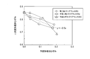
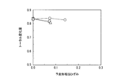
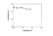
- the strain gradient at the shear edge becomes larger than when cylindrical hole expansion is performed. Therefore, in the specimen A, when the strain gradient is large, as can be seen from FIG. 1, the secondary deformation limit strain decreases as the amount of pre-deformation equivalent strain increases, but as can be seen from FIG. The amount of deformation tends to increase as the amount of pre-deformation equivalent strain increases.
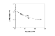
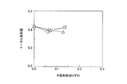
- the secondary deformation limit strain decreases as the amount of pre-deformation equivalent strain increases, but as can be seen from FIG. However, it does not depend much on the amount of pre-deformation equivalent strain, and its correlation with the amount of pre-deformation equivalent strain is low. Further, as can be seen from FIGS. 1 to 4, the influence of the pre-deformation equivalent strain amount (pre-deformation amount, primary deformation amount) on the secondary deformation limit strain does not depend much on the pre-deformation deformation mode. For this reason, it was found that the secondary deformation limit strain can be arranged by the equivalent strain.
- Example 2> For the test material D, an experiment similar to the experiment 1 was performed. The results are shown in FIGS. As can be seen from FIGS. 5 to 8, this sample material D also has the same tendency as the sample material A. ⁇ Experiment 3> The test material E was subjected to the same experiment as the experiment 1. The results are shown in FIGS. As can be seen from FIG. 9 to FIG. 12, the specimen E has a tendency similar to that of the specimen A, but also has the following tendency. That is, when the strain gradient is large, the secondary deformation limit hardly decreases depending on the amount of pre-deformation in a predetermined deformation region. On the other hand, when the strain gradient is small, the total deformation amount depends on the pre-deformation amount and decreases as the pre-deformation amount increases. That is, applying the pre-deformation has an adverse effect.
- the final deformation limit strain of the stretch flange portion by secondary forming including pre-deformation depends on both the primary deformation amount and the strain gradient. Further, the dependence of the primary deformation differs depending on whether the strain gradient is large or small. That is, the accuracy of the evaluation is improved by evaluating the shear edge separately when the strain gradient is small or large with respect to the predetermined strain gradient. This tendency does not depend on the thickness.
- the present invention has been made based on the above new findings. Each embodiment based on this knowledge will be described below.
- the method for evaluating whether or not a shear edge can be formed according to this embodiment is a technique for evaluating whether or not a shear edge can be formed on a primary-formed (pre-formed) metal plate.
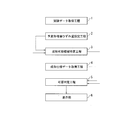
- the moldability evaluation method of the present embodiment includes an experimental data acquisition step 1, a pre-deformation equivalent strain amount setting step 2, a moldable region specifying step 3, a molding specification data acquisition step 4, and a propriety determination step. 5 is provided.
- a hole expansion test is performed on a preliminarily formed metal plate.
- two or more types of hole expansion tests with different radial strain gradients at the shear edges are performed by changing the punch shape to be used or the diameter of the punched hole before diameter expansion.
- the preforming performed on the metal plate to acquire data and the hole expansion test on the preformed metal plate may be performed by the method described in Experiment 1 above. In this case, it is convenient to perform primary molding so that the amount of equivalent strain due to preforming added to the place where hole expansion is performed becomes a constant value.
- the strain gradient of the hole after diameter expansion by each hole expansion test is specified by analysis of the molded product by the test or molding analysis (FEM analysis calculation) performed separately.
- FEM analysis calculation molding analysis
- the deformation limit strain amount generated at the shearing edge of each hole by secondary forming is obtained from the hole expansion rate obtained by each hole expansion test.
- the deformation limit equivalent strain amount is adopted as the deformation limit strain amount to be acquired.
- the strain gradient is expressed as an average gradient of the maximum main strain in a predetermined section (for example, a section from the edge to 5 mm) along the radial direction from the edge of the hole.
- the value of the strain gradient is expressed as an absolute value.
- the experimental data acquisition step 1 acquires a plurality of data with different strain gradients as data consisting of the radial strain gradient at the shear edge and the deformation limit equivalent strain amount in the pre-formed metal plate. To do. The position to acquire is specified by the user.
- Pre-deformation equivalent strain amount setting step 2 was added to the metal plate by pre-forming in the part to be subjected to the hole expansion in the above-mentioned hole expansion test by a preformed molded product or separately performed molding analysis (FEM analysis calculation). The equivalent strain amount is acquired as the pre-deformation equivalent strain amount.
- the pre-deformation equivalent strain amount may be acquired or the primary processing conditions may be set during the hole expansion test.
- the formable region specifying step 3 is a process of expanding flange deformation with respect to a strain gradient from a plurality of data having different strain gradients acquired in the experimental data acquisition step 1 and a pre-deformation equivalent strain amount acquired in the pre-deformation equivalent strain amount setting step 2.
- Find the limit equivalent strain relationship the stretch flange deformation limit equivalent strain is the sum of the deformation limit equivalent strain amount and the predeformation equivalent strain amount. That is, the deformation equivalent to the deformation limit acquired in the experimental data acquisition step 1 is added to the strain equivalent to the pre-deformation obtained in the pre-deformation equivalent strain setting step 2 to obtain an elongation flange deformation limit equivalent strain.
- two or more data having two parameters, ie, strain gradient and stretch flange deformation limit equivalent strain, as parameters (variables) can be obtained as relation generation data.
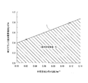
- the horizontal axis represents the strain gradient
- the vertical axis represents the stretch flange deformation limit equivalent strain
- the obtained data strain gradient, stretch flange deformation limit equivalent strain
- a line connecting the plotted points is defined as a forming limit line L.
- the lower region is specified as the moldable region R.
- the data to be acquired is data of two points
- a straight line passing through the two points is set as a forming limit line L as shown in FIG.
- one data preferably has a strain gradient of less than 0.03, and the other data preferably has a strain gradient of 0.06 or more.
- two data having the strain gradient in the range may be adopted. In any case, it is preferable that the two strain gradients are separated by 0.03 or more.
- the data to be acquired is three or more data.
- the forming limit line L obtained in the formable region specifying step 3 may be obtained as a relational expression using (strain gradient, stretch flange deformation limit equivalent strain) as a parameter.
- the moldable region specifying step 3 inputs a plurality of data with different strain gradients acquired in the experimental data acquisition step 1 and pre-deformation equivalent strain amount data acquired in the pre-deformation equivalent strain amount setting step 2. It is preferable that the calculation of the processing is executed by a computer to output and generate information on at least one of the forming limit line L and the moldable region R.
- the molding limit line L may be stored as a formula as a formula.
- calculation processing parts other than the hole expansion test in the experimental data acquisition step 1 may be executed by a computer using a program such as FEM analysis calculation.
- FEM analysis calculation the acquisition of basic information for evaluating whether or not a shear edge can be formed by press forming on a metal plate that has been pre-deformed by pre-forming is completed.
- provisional molding specifications of a molded product created in at least two processes of primary molding and secondary molding are provisionally performed, and FEM analysis calculation is performed on the provisional molding specifications to obtain a pre-formed metal plate.
- the deformation amount and strain gradient of the shearing edge after the completion of the forming are calculated, and the equivalent strain amount generated in the vicinity of the shearing edge by pre-forming is calculated as the predeformation equivalent strain amount.
- data acquisition step 4 in addition to FEM analysis calculation, data may be acquired by performing experiments as necessary.
- the magnitude of the pre-deformation equivalent strain differs depending on the shape applied to the pre-molding and often varies depending on the position of the stretch flange. It is preferable to calculate.
- the representative value may be adopted.
- the feasibility determination step 5 the total deformation amount at the shearing edge after completion of molding, which is obtained in the molding specification data acquisition step 4, is output as the equivalent strain amount at the molding possibility determination target portion. Then, it is determined whether the data set of the total deformation amount and the strain gradient exists in the moldable region R specified by the output information of the moldable region specifying step 3. If it exists in the moldable region R, it is evaluated that molding is possible, and if it is not, it is evaluated that molding is not possible. This evaluation may be automatically performed by a computer. Then, the evaluation is displayed on the display unit 6.
- the acquisition data for the shear edge evaluation in the provisional molding specification is not limited to one place, but may be obtained at a plurality of shear edges and each of the above-described evaluation of the possibility of forming may be performed. Then, if there is a molding-impossible shear edge, re-form a provisional molding specification (pre-molding specification and post-molding specification) that changes the specifications in the vicinity of the molding-impossible shear edge, The molding specification data acquisition step 4 and the availability determination step 5 are repeated. Then, the final forming specification for the pre-formed metal plate is determined from the provisional forming specification which can be formed at all the set shear edge portions.
- This embodiment has the following effects. (1) Acquire a plurality of deformation limit equivalent strain data in the pre-formed metal plate with respect to the strain gradient at the shear edge, and obtain the relationship between the strain corresponding to the stretch flange deformation limit and the strain gradient based on the data. By specifying the forming limit line L from the obtained relationship, the formable region R of the shear edge is specified. Then, based on the specified forming limit line L and the formable region R, whether or not forming is possible is evaluated with respect to the total deformation amount with respect to the strain gradient at the shear edge obtained from the provisional forming specification.
- the inventor has confirmed that the strain corresponding to the stretch flange deformation limit, which is the sum of the deformation limit equivalent strain amount and the predeformation equivalent strain amount, is large when the strain gradient is small. It doesn't depend much. On the other hand, when the strain gradient is large, the stretch flange deformation limit equivalent strain tends to increase as the pre-deformation equivalent strain amount increases.
- the reference strain gradient range was set to 0.03 or more and 0.06 or less. Preferably, it is 0.04 or more and 0.05 or less.
- the strain gradient of the part where the determination of whether or not stretch flange forming in secondary molding is a problem in various automotive press products was examined, it was roughly classified as less than 0.03 or 0.06 or more. Depending on the hole diameter, in many cases, the strain gradient is 0.06 or more in the conical hole expansion test, and the strain gradient is less than 0.03 in the cylindrical hole expansion test. From the above, the reference strain gradient as a boundary is set to the above range.
- a reference strain gradient is selected from a reference strain gradient range of 0.03 or more and 0.06 or less.
- 0.05 is set as the reference strain gradient. And it divides into two, the 1st field where a strain gradient is less than a standard strain gradient, and the 2nd field where a strain gradient is more than a standard strain gradient.
- a plurality of data with different strain gradients are obtained using the radial strain gradient at the shear edge and the deformation limit equivalent strain amount for the metal plate after the preforming as parameters.
- two or more first data composed of a strain gradient smaller than the reference strain gradient and two or more second data composed of a strain gradient larger than the reference strain gradient are individually used as a plurality of data. get.
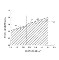
- the pre-deformation equivalent strain amount setting step 2 and the moldable region specifying step 3 are performed for each of the first data and the second data. Thereby, as an output of the moldable region specifying step 3, from at least one of the first molding limit line L1 and the first moldable region R1 that target the first region whose strain gradient is less than the reference strain gradient. And second information consisting of at least one of the second molding limit line L2 and the second moldable region R2 for the second region whose strain gradient is equal to or greater than the reference strain gradient. (See FIG. 15).
- the molding specifications of the molded product created by performing the primary molding and the secondary molding are provisionally performed, the FEM analysis calculation is performed on the provisional molding specifications, The deformation amount and strain gradient of the shearing edge after completion of forming the pre-formed metal plate are obtained, and the equivalent strain amount generated in the vicinity of the shearing edge by pre-forming is calculated as the predeformation equivalent strain amount. That is, a strain gradient generated at a target shear edge by press molding is estimated by a molded product or molding analysis.
- the deformation amount of the shearing edge after the completion of molding obtained in the molding specification data acquisition step 4 is obtained as an equivalent strain amount in the molding propriety determination portion, and the obtained deformation amount and strain gradient are calculated. It is determined whether the data set exists in the moldable area specified by the output information of the moldable area specifying step 3. At this time, if the target strain gradient is the first region, the first information is used to determine whether the target strain gradient is the second region. If the target strain gradient is the second region, the second information is determined. Use the to determine whether or not.
- the moldability evaluation method of the present embodiment includes an experimental data acquisition step 7 without preforming, a moldable region specifying step 8 without preforming, a conversion step 9 after preforming, and molding.
- a specification data acquisition step 4 and an availability determination step 5 are provided.
- a hole expansion test is performed on a metal plate without pre-forming (the metal plate before pre-forming), and the radial strain gradient at the shear edge and the metal plate A plurality of data having different strain gradients with the deformation limit equivalent strain amount as a parameter is obtained.
- Formable region specifying step 8 without preforming is the relationship between the strain limit equivalent strain amount and the strain gradient for the metal plate without preforming from a plurality of data obtained by the experimental data acquisition step 7 without preforming. Ask for.
- the horizontal axis indicates the strain gradient and the vertical axis indicates the deformation limit equivalent strain
- the obtained plural data are plotted.
- a line connecting the plotted points is defined as a forming limit line L0 without pre-forming.
- the molding limit line L0 without pre-molding may be obtained by the method described in Japanese Patent No. 4935713.
- the formable region without preforming is specified by the molding limit line L0 without preforming.
- the deformation limit equivalent strain without pre-forming is converted into the equivalent strain corresponding to the stretch flange deformation limit with respect to the forming limit line L0 without pre-forming, using the strain gradient as a parameter.
- the forming limit line with pre-forming corresponding to the stretch flange deformation limit equivalent strain with respect to the strain gradient at the shear edge in the pre-formed metal plate by adding the converted values k1, k2 for each region Lx is obtained.
- the equivalent strain applied to the metal plate in the pre-forming is defined as the pre-deformation equivalent strain, and the pre-deformation equivalent strain and the deformation limit in the metal plate after the pre-forming.
- the sum of the equivalent strain is defined as the strain equivalent to the stretch flange deformation limit.
- required in the conversion process 9 after pre-molding is made into the moldable area
- the converted values k1 and k2 are values having a strain gradient as a variable.
- the converted value k2 when the strain gradient is equal to or higher than the reference strain gradient is smaller than the converted value k1 when the strain gradient is less than the reference strain gradient. Is set to be larger. This is based on the above findings and takes into account that when the strain gradient is large, it tends to increase with an increase in preforming than when the strain gradient is small.
- the reference strain gradient is selected from the range of 0.03 or more and 0.06 or less of the reference strain gradient as described above. In the present embodiment, for example, 0.05 is set as the reference strain gradient.
- provisional molding specifications of a molded product created by performing primary molding and secondary molding are provisionally performed, and FEM analysis calculation is performed on the provisional molding specifications to obtain a metal plate after preforming.
- the deformation amount and strain gradient of the shearing edge after forming is calculated for the above, and the deformation equivalent strain amount generated in the vicinity of the shearing edge by pre-forming is calculated as the predeformation equivalent strain amount.
- the deformation amount of the shear edge after the completion of molding obtained in the molding specification data acquisition step 4 is obtained as an equivalent strain amount in the molding feasibility determination portion, and a data set of the obtained deformation amount and strain gradient is obtained. Is present in the formable region R specified by the output information of the conversion step 9 after pre-molding. If it exists in the moldable region R, it is evaluated that molding is possible, and if it is not, it is evaluated that molding is not possible.
- the processing of the molding specification data acquisition step 4 and the availability determination step 5 may be the same processing as in the first embodiment.
- the deformation equivalent strain amount by pre-forming at the shear edge position to be evaluated is acquired, and the strain gradient of the shear edge is acquired.
- the acquired strain gradient is less than the reference strain gradient
- the acquired strain gradient is greater than or equal to the reference strain gradient
- ⁇ eq1 is a pre-deformation equivalent strain amount.
- the feasibility determination step 5 determines the molding limit value with preforming by using the calculated conversion value for the strain gradient to be evaluated, and determines whether it exists in the moldable region R.
- ⁇ ⁇ 0.5 to 0.5 to the constant deformation equivalent strain amount at the time of preforming.
- the coefficients ⁇ and ⁇ are determined as follows. .
- ⁇ and ⁇ are preferably determined by the following equations.
- ⁇ 1-R
- ⁇ 1-R
- Table 2 for example, the case of “low strain gradient” corresponds to the case where the acquired strain gradient is less than the reference strain gradient, and the case of “large strain gradient” indicates that the acquired strain gradient is greater than or equal to the reference strain gradient. It corresponds to.
- the present embodiment it is possible to easily evaluate whether or not a shear edge can be formed from experimental data obtained without pre-forming.
- the accuracy of the forming limit line may be lower than in the first embodiment.
- the pre-deformation equivalent strain amount in the pre-molding can be changed by the molding specification
- the final molding specification is obtained by changing the pre-deformation equivalent strain amount side as well. Is also possible.
Landscapes
- Engineering & Computer Science (AREA)
- Mechanical Engineering (AREA)
- Physics & Mathematics (AREA)
- Health & Medical Sciences (AREA)
- Life Sciences & Earth Sciences (AREA)
- Chemical & Material Sciences (AREA)
- Analytical Chemistry (AREA)
- Biochemistry (AREA)
- General Health & Medical Sciences (AREA)
- General Physics & Mathematics (AREA)
- Immunology (AREA)
- Pathology (AREA)
- Shaping Metal By Deep-Drawing, Or The Like (AREA)
- Punching Or Piercing (AREA)
- Investigating Strength Of Materials By Application Of Mechanical Stress (AREA)
Abstract
Description
しかしながら、上記のプレス品のせん断縁における成形可否判定方法は、いずれも予変形(一次成形)を受けずにせん断された材料縁を評価するものであって、予変形を受けた後にせん断された材料縁への適用については何ら考慮されていない。
このように、一次成形を受けた後のせん断縁における成形可否の判定精度については従来から問題があり、金型作製後でないと成形可否が不明確であるとの課題があった。
すなわち、金型を何度も作成することなく、二次成形における伸びフランジ部での成形可否や成形余裕度などの評価が精度よく予測できる結果、割れ発生による不良を早期に予防することが出来る。
上記の従来技術による、加工によるせん断縁の成形可否の判定方法の評価は、いずれも予変形(一次成形)を受けていない状態からのせん断縁に関する変形限界だけの評価を想定したものである。このため、上記の従来技術の評価方法が、一次成形を受けた後のせん断縁に関する成形可否の判定にも直接展開できるかどうかは不明であった。なぜなら、せん断によるダメージが、予成形によって生じる一次変形量に依存しないとは言い切れないためである。
以下、その内容について説明する。
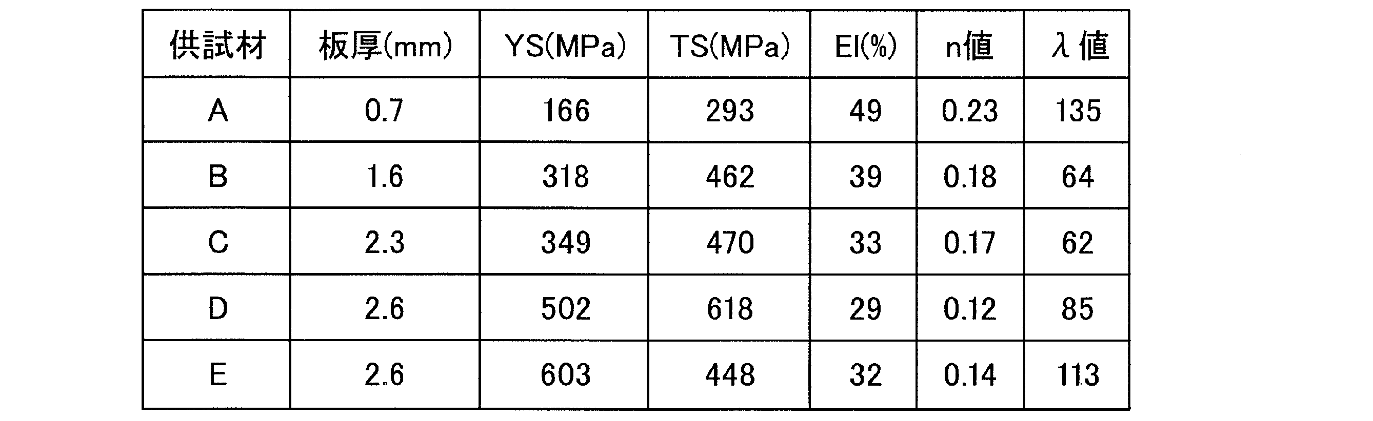
ここで、表1に示す供試材A~Eを使用して、一次成形(予変形)を付与した金属板に対して、各種の穴広げ試験を実施した。穴広げ試験としては、円錐形状のポンチを使用した円錐穴広げ試験と、円筒形状のポンチを使用した円筒穴広げ試験とを実施した。
なお、半径方向のひずみ勾配は、使用するポンチの形状や予成形後の抜き穴径を変更することで調整可能である。
供試材Aからなる金属板に対して、円錐穴広げ試験を行った。
そして、予成形による予変形相当ひずみに対する、予成形後の金属板における二次変形限界ひずみで纏めたところ、図1に示す結果を得た。また、予成形による予変形相当ひずみに対する、予変形相当ひずみと二次変形限界ひずみとの和であるトータル変形量で纏めたところ、図2に示す結果を得た。
そして、予成形による予変形相当ひずみに対する、予成形後の金属板における二次変形限界ひずみで纏めたところ、図3に示す結果を得た。また、予成形による予変形相当ひずみに対する、予変形相当ひずみと二次変形限界ひずみとの和であるトータル変形量で纏めたところ、図4に示す結果を得た。
○:等二軸によるひずみ
□:不等二軸によるひずみ
△:平面ひずみによるひずみ
である。
したがって、供試材Aでは、ひずみ勾配が大きい場合には、図1から分かるように、二次変形限界ひずみは、予変形相当ひずみ量が増えるほど小さくなるが、図2から分かるように、トータル変形量では、予変形相当ひずみ量が増加するほど、増加する傾向にある。
また、図1~図4から分かるように、二次変形限界ひずみに及ぼす予変形相当ひずみ量(予変形量、一次変形量)の影響は、予変形の変形形態にあまり依存しない。このため二次変形限界ひずみは相当ひずみで整理できることをつきとめた。
供試材Dについて、実験1と同様な実験を行った。その結果を図5~図8に示す。
この供試材Dにおいても、図5~図8から分かるように、供試材Aと同様な傾向があることが分かる。
〈実験3〉
供試材Eについて、実験1と同様な実験を行った。その結果を図9~図12に示す。
供試材Eにおいても、図9~図12から分かるように、供試材Aと似た傾向はあるものの、次のような傾向もあることが分かる。
即ち、ひずみ勾配が大きい場合、所定の変形領域では、予変形量によって二次変形限界はほとんど低下しない。一方、ひずみ勾配が小さい場合、トータル変形量が、予変形量に依存性があり、予変形量の増加に伴い減少する。つまり、予変形を付与することが逆効果となる。
供試材B、Cについても実験1と同様な実験を行った。
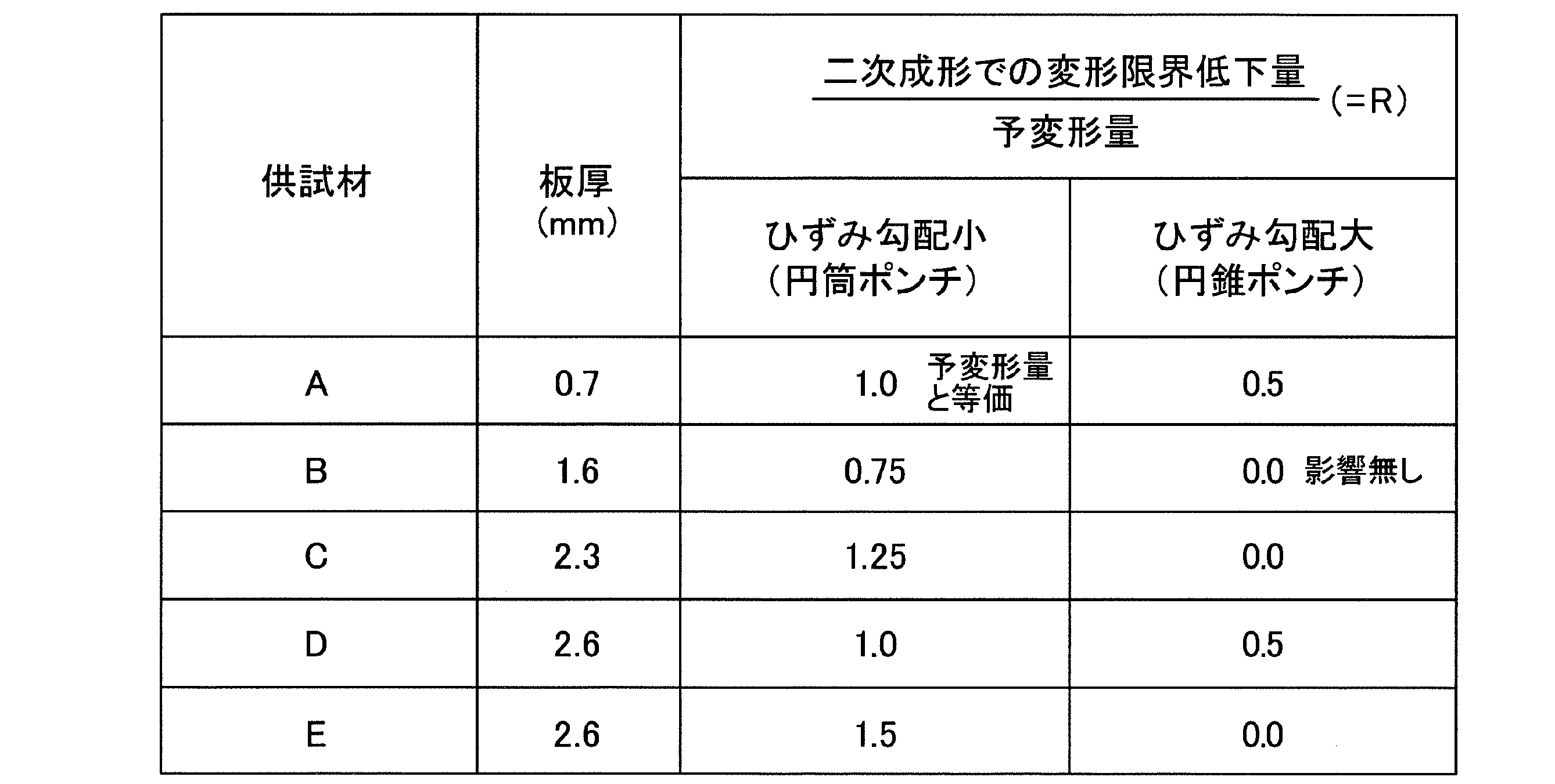
そして、上記の結果を、予変形量(予変形相当ひずみ量)に対する(二次成形での変形限界量の低下量)の比で纏めると、表2に示す結果となった。
以上の実験から、発明者は、以下のような知見を得た。
(1)せん断後の変形限界ひずみに対する一次変形量の影響度は、せん断後の変形限界ひずみの変形形態(等二軸、不等二軸、平面ひずみ)にあまり依存せず、相当ひずみで整理できる。
このため、本発明では、相当ひずみで評価している。
また、一次変形の依存性は、ひずみ勾配が大きい場合と小さい場合とで異なる。すなわち、所定のひずみ勾配に対し、ひずみ勾配が小さい場合と大きい場合とに別けて、せん断縁を評価する方が、評価の精度が向上する。なお、この傾向は厚さには依存性がない。
本発明は、以上のような新たな知見に基づきなされたものである。
以下に、この知見に基づく各実施形態について説明する。
次に、本実施形態のせん断縁の成形可否評価方法について、図面を参照しつつ説明する。
本実施形態のせん断縁の成形可否評価方法は、一次成形(予成形)された金属板に対するせん断縁の成形可否を評価する技術である。
本実施形態の成形可否評価方法は、図13に示すように、実験データ取得工程1、予変形相当ひずみ量設定工程2、成形可能領域特定工程3、成形仕様データ取得工程4、及び可否判定工程5を備える。
実験データ取得工程1は、予め設定した予成形を施した金属板に対して穴広げ試験を実施する。穴広げ試験では、使用するポンチ形状あるいは拡径前の抜き穴の径を変えることで、せん断縁での径方向のひずみ勾配が異なる2種類以上の穴広げ試験を実施する。
ここで、各穴広げ試験によって拡径した後の穴のひずみ勾配は、その試験による成形品の分析あるいは別途実施した成形分析(FEM解析計算)によって特定する。また、各穴広げ試験による穴広げ率から、二次成形による、各穴のせん断縁に発生した変形限界ひずみ量を求める。本実施形態では取得する変形限界ひずみ量として変形限界相当ひずみ量を採用する。
λ=((d-d0)/d0)×100
本実施形態では、ひずみ勾配を、穴の縁からの半径方向に沿った所定区間(例えば縁から5mmまでの区間)での最大主ひずみの平均勾配で表現する。なお、本実施形態では、ひずみ勾配の値は絶対値で表現する。
予変形相当ひずみ量設定工程2は、予成形した成形品又は別途実施した成形分析(FEM解析計算)によって、上記の穴広げ試験の穴広げを行う部分における、予成形で金属板に加えられた相当ひずみ量を予変形相当ひずみ量として取得する。予変形相当ひずみ量は、上記穴広げ試験の際に取得若しくは一次加工条件を設定すればよい。
ここで、伸びフランジ変形限界相当ひずみは、変形限界相当ひずみ量と予変形相当ひずみ量との和である。すなわち、実験データ取得工程1で取得した変形限界相当ひずみ量に、予変形相当ひずみ量設定工程2で取得した予変形相当ひずみ量を加算して、伸びフランジ変形限界相当ひずみとする。
そして、図14のように横軸にひずみ勾配をとり、縦軸に伸びフランジ変形限界相当ひずみをとって、求めた複数の(ひずみ勾配、伸びフランジ変形限界相当ひずみ)のデータをプロットし、そのプロットした点を結んだ線を成形限界線Lとする。そして成形限界線Lを境界として、その下側の領域を成形可能領域Rとして特定する。
また、プロットするデータが3点以上の場合には、隣り合う各点を直線で結んだ線を成形限界線Lとしたり、その複数のデータを通過する曲線を成形限界線Lとしたりする。
上記成形可能領域特定工程3は、実験データ取得工程1が取得したひずみ勾配が異なる複数のデータと、予変形相当ひずみ量設定工程2が取得した予変形相当ひずみ量のデータとを入力し、上記処理の演算をコンピュータで実行して上記成形限界線L及び成形可能領域Rの少なくとも一方の情報をアウトプットして生成するように構成しておくと良い。成形限界線Lは式として、その式の係数を記憶しておいても良い。
以上の処理によって、予成形によって予変形を加えた金属板に対するプレス成形によるせん断縁の成形可否を評価するための基礎情報の取得が終了する。
成形仕様データ取得工程4では、一次成形及び二次成形の少なくとも2工程で作成される成形品の成形仕様を暫定し、この暫定した成形仕様についてFEM解析計算を行って、予成形後の金属板に対する成形完了後のせん断縁の変形量及びひずみ勾配を求めると共に、予成形によって、上記のせん断縁近傍に発生する相当ひずみ量を予変形相当ひずみ量として演算する。この成形仕様データ取得工程4において、FEM解析計算に加え、必要に応じて適宜実験を行ってデータを取得するようにしても良い。
可否判定工程5では、成形仕様データ取得工程4で求めた、成形完了後のせん断縁でのトータルの変形量を成形可否判定対象部位での相当ひずみ量として出力する。そして、そのトータルの変形量とひずみ勾配とのデータ組が、成形可能領域特定工程3の出力情報で特定される成形可能領域R内に存在するか判定する。成形可能領域R内に存在する場合には、成形可と評価し、そうでない場合には、成形否と評価する。この評価はコンピュータで自動演算させても構わない。そして、その評価を表示部6に表示する。
そして、成形否のせん断縁が存在している場合には、その成形否のせん断縁近傍の仕様を変更した暫定した成形仕様(予成形の仕様と予成形後の仕様)を策定し直して、上記の成形仕様データ取得工程4及び可否判定工程5を繰り返す。そして、設定した全てのせん断縁箇所で成形可となった暫定の成形仕様から、予成形した金属板に対する最終の成形仕様を決定する。
ここで、使用する金属板の鋼種毎に成形限界線Lを求めて、使用するようにすればよい。
また上記の成形評価では、可否判定を例示したが、どの程度、余裕が有るか、どの程度変形量がオーバーしているかで評価しても良い。
本実施形態では、次のような効果を奏する。
(1)せん断縁でのひずみ勾配に対する予成形後の金属板での変形限界相当ひずみ量のデータを複数取得し、その複数のデータに基づき、ひずみ勾配に対する伸びフランジ変形限界相当ひずみの関係を求め、求めた関係から成形限界線Lを特定することで、せん断縁の成形可能領域Rを特定する。そして、特定した成形限界線Lや成形可能領域Rに基づき、暫定した成形仕様から求められるせん断縁でのひずみ勾配に対するトータルの変形量に対し、成形可否を評価する。
すなわち、金型を何度も作成することなく、二次成形における伸びフランジ部での成形可否や成形余裕度などの評価が精度よく予測できる結果、割れ発生による不良を早期に予防することが出来る。
また相当ひずみで評価することで、ひずみ形態の違いを考慮する必要もない。
ここで、上記の実施形態では、一つの連続した成形限界線Lを求める場合で説明している。これに対し、本変形例では、ひずみ勾配が0.03以上0.06以下の基準ひずみ勾配範囲内に基準のひずみ勾配を設定して、その基準のひずみ勾配を境に2つの領域に区分し、区分毎に成形限界線L1,L2を求める。
また、穴径にもよるが、多くのケースで、円錐穴広げ試験ではひずみ勾配が0.06以上に、円筒穴広げ試験ではひずみ勾配が0.03未満になる。
以上のことから、境界となる基準のひずみ勾配を上記範囲とした。
まず0.03以上0.06以下の基準ひずみ勾配範囲から、基準のひずみ勾配を選択する。本実施形態では、例えば基準のひずみ勾配として0.05を設定する。
そして、ひずみ勾配が基準のひずみ勾配未満の第1の領域と、ひずみ勾配が基準のひずみ勾配以上の第2の領域との2つに区分する。
これによって、成形可能領域特定工程3のアウトプットとして、ひずみ勾配が基準のひずみ勾配未満の第1の領域を対象とする第1の成形限界線L1及び第1の成形可能領域R1の少なくとも一方からなる第1の情報と、ひずみ勾配が基準のひずみ勾配以上の第2の領域を対象とする第2の成形限界線L2及び第2の成形可能領域R2の少なくとも一方からなる第2の情報を得る(図15参照)。
本変形例の評価方法の効果は、第1実施形態と同様であるが、ひずみ勾配に応じて2つの領域に分けて評価している。このため、ひずみ勾配が大きい場合と小さい場合との傾向違いを考慮して評価することが可能となる。
次に、第2実施形態について図面を参照して説明する。第1実施形態と同様な構成については同一の符号を付して説明する。
本実施形態の成形可否評価方法は、図16に示すように、予成形無しでの実験データ取得工程7、予成形無しでの成形可能領域特定工程8、予成形後への変換工程9、成形仕様データ取得工程4、及び可否判定工程5を備える。
予成形無しでの成形可能領域特定工程8は、予成形無しでの実験データ取得工程7が求めた複数のデータから、予成形無しでの金属板に対する、ひずみ勾配に対する変形限界相当ひずみ量の関係を求める。
この予成形無しでの成形限界線L0は、特許第4935713号公報に記載の方法によって求めても構わない。この予成形無しでの成形限界線L0によって、予成形無しでの成形可能領域が特定される。
そして、予成形後への変換工程9で求めた、予変形有りでの成形限界線Lx以下の領域を成形可能領域Rとする。
これは、上記の知見に基づき、ひずみ勾配が大きい場合、ひずみ勾配が小さい場合よりも予成形の増加によって増加する傾向があることを考慮したものである。
成形仕様データ取得工程4では、一次成形及び二次成形が行われて作成される成形品の成形仕様を暫定し、この暫定した成形仕様についてFEM解析計算を行って、予成成形後の金属板に対する成形完了後のせん断縁の変形量及びひずみ勾配を求めると共に、予成形によって、上記のせん断縁近傍に発生する変形相当ひずみ量を予変形相当ひずみ量として演算する。
ここで、成形仕様データ取得工程4及び可否判定工程5の処理は、第1実施形態と同様な処理で構わない。
この換算値k1,k2は、基準のひずみ勾配を境界とした各ひずみ勾配の領域内から代表点を任意に設定し、その代表点において、それぞれの予変形無しでの成形限界値と予成形有りでの成形限界値とを実験などで求めて、その差を、各領域での各換算値k1,k2としてもよい。
成形仕様データ取得工程4から、評価するせん断縁位置での予成形による変形相当ひずみ量を取得すると共に、そのせん断縁のひずみ勾配を取得する。
そして、取得したひずみ勾配が基準ひずみ勾配未満の場合には、取得した変形相当ひずみ量に対してα=-0.5~0.5の範囲から選択した係数を乗算して換算値とする。また、取得したひずみ勾配が基準ひずみ勾配以上の場合には、取得した変形相当ひずみ量に対してβ=0.5~1.0の範囲から選択した係数を乗算して換算値とする。
k1=α×εeq1
k2=β×εeq1
となる。
但し、εeq1は予変形相当ひずみ量である。
ここで、成形品作成時における、予成形時の変形相当ひずみ量が一定である場合には、その一定の予成形時の変形相当ひずみ量に対して、α=-0.5~0.5の範囲から選択した係数を乗算して、基準ひずみ勾配未満のひずみ勾配に対する換算値とし、一定の予成形時の変形相当ひずみ量に対して、β=0.5~1.0の範囲から選択した係数を乗算して、基準ひずみ勾配以上のひずみ勾配に対する換算値として、予め決定する。
ここで、α、βは次式で決定するのがよい。
α=1-R
β=1-R
例えば、表2に示したような「二次成形での変形限界低下量/予変形量」=Rの比によって上記の乗算する係数を決定すればよい。表2では、例えば、「ひずみ勾配小」の場合が、取得したひずみ勾配が基準ひずみ勾配未満の場合に相当し、「ひずみ勾配大」の場合が、取得したひずみ勾配が基準ひずみ勾配以上の場合に相当する。
この場合、成形限界線の精度が第1実施形態よりも低いおそれがある。
ここで、全実施形態において、予成形の際の予変形相当ひずみ量を成形仕様で変更可能である場合には、予変形相当ひずみ量側も変更することで、最終的な成形仕様を求めることも可能である。
ここでは、限られた数の実施形態を参照しながら説明したが、権利範囲はそれらに限定されるものではなく、上記の開示に基づく各実施形態の改変は当業者にとって自明なことである。
2 予変形相当ひずみ量設定工程
3 成形可能領域特定工程
4 成形仕様データ取得工程
5 可否判定工程
6 表示部
7 予成形無しでの実験データ取得工程
8 予成形無しでの成形可能領域特定工程
9 予成形後への変換工程
k1,k2 換算値
L 成形限界線
L0 予成形無しでの成形限界線
L1,L2 成形限界線
Lx 成形限界線
R 成形可能領域
R1 成形可能領域
R2 成形可能領域
Claims (6)
- 予成形によって予変形を加えた金属板に対するプレス成形によるせん断縁の成形可否を評価する評価方法であって、
予成形後の金属板に対する穴広げ試験によってせん断縁での変形限界を求め、求めたせん断縁での変形限界量を変形限界相当ひずみ量で表現して、せん断縁での径方向のひずみ勾配に対する上記穴広げ試験によって求めた変形限界相当ひずみ量からなるデータとして、ひずみ勾配が異なる複数のデータを取得し、
上記予成形で上記金属板に加えられる相当ひずみ量を予変形相当ひずみ量と定義し、その予変形相当ひずみ量と上記予成形後の金属板での変形限界相当ひずみ量との和を伸びフランジ変形限界相当ひずみと定義し、
上記予変形相当ひずみ量と上記複数のデータとに基づき、ひずみ勾配に対する伸びフランジ変形限界相当ひずみの関係を求め、
上記求めた関係からせん断縁の成形可能領域を特定して、予成形によって予変形を加えた金属板に対するせん断縁の成形可否を評価することを特徴とするせん断縁の成形可否評価方法。 - 予成形によって予変形を加えた金属板に対するプレス成形によるせん断縁の成形可否を評価する評価方法であって、
予成形後の金属板に対する穴広げ試験によってせん断縁での変形限界を求め、求めたせん断縁での変形限界量を変形限界相当ひずみ量で表現して、せん断縁での径方向のひずみ勾配に対する上記穴広げ試験によって求めた変形限界相当ひずみ量からなる複数のデータを取得し、
上記複数のデータは、予め設定した基準のひずみ勾配より小さいひずみ勾配からなる2以上の第1のデータと、上記基準となるひずみ勾配よりも大きなひずみ勾配からなる2以上の第2のデータとを有し、
上記予成形で上記金属板に加えられる相当ひずみ量を予変形相当ひずみ量と定義し、その予変形相当ひずみ量と上記予成形後の金属板での変形限界相当ひずみ量との和を伸びフランジ変形限界相当ひずみと定義し、
上記予変形相当ひずみ量と上記2以上の第1のデータに基づき、ひずみ勾配に対する伸びフランジ変形限界相当ひずみの関係である第1の関係を求め、
上記予変形相当ひずみ量と上記2以上の第2のデータに基づき、ひずみ勾配に対する伸びフランジ変形限界相当ひずみの関係である第2の関係を求め、
上記プレス成形によって対象とするせん断縁に発生するひずみ勾配を推定し、
上記推定したひずみ勾配が、上記基準のひずみ勾配未満の場合には、上記第1の関係によってせん断縁の第1の成形可能領域を特定してプレス成形によるせん断縁の成形可否を評価し、上記推定したひずみ勾配が、上記基準のひずみ勾配以上の場合には、上記第2の関係によってせん断縁の第2の成形可能領域を特定してプレス成形によるせん断縁の成形可否を評価することを特徴とするせん断縁の成形可否評価方法。 - 上記基準のひずみ勾配は、0.03以上0.06以下の範囲から選択することを特徴とする請求項2に記載したせん断縁の成形可否評価方法。
- 予成形によって予変形を加えた金属板に対するプレス成形によるせん断縁の成形可否を評価する評価方法であって、
予成形無しでの金属板に対する穴広げ試験によってせん断縁での変形限界を求め、求めたせん断縁での変形限界量を変形限界相当ひずみ量で表現して、上記予成形無しでの金属板における、せん断縁での径方向のひずみ勾配に対する上記穴広げ試験によって求めた変形限界相当ひずみ量からなるデータであって、ひずみ勾配が異なる複数のデータを取得し、
上記複数のデータから、上記予成形無しでの金属板における、ひずみ勾配に対する予成形無しでの変形限界相当ひずみ量の関係である予成形無しでの関係を求め、
予成形で上記金属板に加えられる相当ひずみ量を予変形相当ひずみ量と定義し、その予変形相当ひずみ量と上記予成形後の金属板での変形限界相当ひずみ量との和を伸びフランジ変形限界相当ひずみと定義し、
上記求めた予成形無しでの関係における変形限界相当ひずみ量を上記伸びフランジ変形限界相当ひずみ相当に変換するための換算値を、当該変形限界相当ひずみ量に加算して、ひずみ勾配に対する伸びフランジ変形限界相当ひずみの関係である予成形有りでの関係を求め、
上記求めた予成形有りでの関係からせん断縁の成形可能領域を特定して、予成形によって予変形を加えた金属板に対するせん断縁の成形可否を評価することを特徴とするせん断縁の成形可否評価方法。 - 上記換算値として、予め設定した基準のひずみ勾配以上の場合の換算値を、上記基準のひずみ勾配未満の場合の換算値よりも大きい値に設定することを特徴とする請求項4に記載したせん断縁の成形可否評価方法。
- 上記換算値は、予め設定した基準のひずみ勾配未満の場合、評価するせん断縁での上記予変形相当ひずみ量の-0.5倍以上0.5倍以下の範囲から選択した値を換算値とし、上記基準のひずみ勾配以上の場合、評価するせん断縁での上記予変形相当ひずみ量の0.5倍以上1.0倍以下の範囲から選択した値を換算値とすることを特徴とする請求項4又は請求項5に記載したせん断縁の成形可否評価方法。
Priority Applications (3)
| Application Number | Priority Date | Filing Date | Title |
|---|---|---|---|
| KR1020177030625A KR101993545B1 (ko) | 2015-05-08 | 2016-05-02 | 전단 에지의 성형 가부 평가 방법 |
| MX2017014240A MX2017014240A (es) | 2015-05-08 | 2016-05-02 | Metodo para evaluar la viabilidad de formacion un borde cizallado. |
| CN201680025732.3A CN107532980B (zh) | 2015-05-08 | 2016-05-02 | 剪切边缘能否成型的评价方法 |
Applications Claiming Priority (2)
| Application Number | Priority Date | Filing Date | Title |
|---|---|---|---|
| JP2015095861A JP6098664B2 (ja) | 2015-05-08 | 2015-05-08 | せん断縁の成形可否評価方法 |
| JP2015-095861 | 2015-05-08 |
Publications (1)
| Publication Number | Publication Date |
|---|---|
| WO2016181892A1 true WO2016181892A1 (ja) | 2016-11-17 |
Family
ID=57248069
Family Applications (1)
| Application Number | Title | Priority Date | Filing Date |
|---|---|---|---|
| PCT/JP2016/063604 Ceased WO2016181892A1 (ja) | 2015-05-08 | 2016-05-02 | せん断縁の成形可否評価方法 |
Country Status (5)
| Country | Link |
|---|---|
| JP (1) | JP6098664B2 (ja) |
| KR (1) | KR101993545B1 (ja) |
| CN (1) | CN107532980B (ja) |
| MX (1) | MX2017014240A (ja) |
| WO (1) | WO2016181892A1 (ja) |
Cited By (4)
| Publication number | Priority date | Publication date | Assignee | Title |
|---|---|---|---|---|
| JP2016144825A (ja) * | 2015-02-09 | 2016-08-12 | 日新製鋼株式会社 | 2次プレス加工性評価方法 |
| JP2017109227A (ja) * | 2015-12-17 | 2017-06-22 | 日新製鋼株式会社 | 伸びフランジ性の評価方法 |
| CN113573823B (zh) * | 2019-03-14 | 2023-09-05 | 杰富意钢铁株式会社 | 拉伸翻边裂纹评价方法及金属板的选定方法 |
| CN121074030A (zh) * | 2025-11-06 | 2025-12-05 | 西安嘉和华亨热系统有限公司 | 一种基于机器视觉的换热器翅片变形程度检测方法及系统 |
Families Citing this family (5)
| Publication number | Priority date | Publication date | Assignee | Title |
|---|---|---|---|---|
| WO2019017136A1 (ja) * | 2017-07-20 | 2019-01-24 | Jfeスチール株式会社 | 金属板のせん断加工面での変形限界の評価方法、割れ予測方法およびプレス金型の設計方法 |
| JP6870670B2 (ja) * | 2018-09-13 | 2021-05-12 | Jfeスチール株式会社 | 変形限界の評価方法、割れの予測方法及びプレス金型の設計方法 |
| KR102482506B1 (ko) * | 2019-02-26 | 2022-12-28 | 제이에프이 스틸 가부시키가이샤 | 굽힘 균열 평가 방법, 굽힘 균열 평가 시스템, 및 프레스 성형 부품의 제조 방법 |
| JP7092107B2 (ja) * | 2019-12-26 | 2022-06-28 | Jfeスチール株式会社 | 伸びフランジ性評価方法、プレス金型設計方法、及びプレス部品の製造方法 |
| CN113588421A (zh) * | 2021-08-04 | 2021-11-02 | 唐山钢铁集团有限责任公司 | 一种金属板材剪切边成形性能的评价方法 |
Citations (4)
| Publication number | Priority date | Publication date | Assignee | Title |
|---|---|---|---|---|
| JP2007232714A (ja) * | 2006-02-01 | 2007-09-13 | Nippon Steel Corp | 破断限界取得方法及び装置、並びにプログラム及び記録媒体 |
| JP2007232715A (ja) * | 2006-02-01 | 2007-09-13 | Nippon Steel Corp | 破断予測方法及び装置、並びにプログラム及び記録媒体 |
| JP2009204427A (ja) * | 2008-02-27 | 2009-09-10 | Jfe Steel Corp | プレス品のせん断縁における成形可否判別方法 |
| JP2014115269A (ja) * | 2012-11-19 | 2014-06-26 | Jfe Steel Corp | 伸びフランジの限界ひずみ特定方法およびプレス成形可否判定方法 |
Family Cites Families (14)
| Publication number | Priority date | Publication date | Assignee | Title |
|---|---|---|---|---|
| JPS4935713A (ja) | 1972-08-08 | 1974-04-02 | ||
| JPS5472518A (en) | 1977-11-19 | 1979-06-11 | Yuuji Miyashita | Mechanism of controlling revolution in automatic plug closing device |
| JPS5561203A (en) | 1978-10-27 | 1980-05-08 | Mitsubishi Electric Corp | Panel unit |
| CN101379381B (zh) * | 2006-02-01 | 2012-08-22 | 新日本制铁株式会社 | 断裂预测方法 |
| CN101657712B (zh) * | 2007-04-12 | 2012-02-22 | 新日本制铁株式会社 | 断裂预测方法、运算处理装置 |
| JP5146395B2 (ja) * | 2008-08-20 | 2013-02-20 | 新日鐵住金株式会社 | 歪勾配を考慮した伸びフランジ割れの推定方法およびプレス成形シミュレーションの伸びフランジ割れ判定システム |
| JP5630311B2 (ja) * | 2011-02-16 | 2014-11-26 | Jfeスチール株式会社 | プレス成形における割れ予測方法およびプレス部品の製造方法 |
| CN202101900U (zh) * | 2011-05-25 | 2012-01-04 | 山东大学 | 一种基于dic技术的板料成形性能测试装置 |
| KR20140131387A (ko) * | 2012-04-16 | 2014-11-12 | 제이에프이 스틸 가부시키가이샤 | 프레스 성형에 있어서의 성형 한계선도의 작성 방법, 균열 예측 방법 및 프레스 부품의 제조 방법 |
| CN102661899A (zh) * | 2012-05-07 | 2012-09-12 | 同济大学 | 金属板材成形极限图的建立和使用方法 |
| BR112014027992B1 (pt) * | 2012-05-08 | 2019-09-17 | Tata Steel Ijmuiden Bv | Chapa de aço laminada à quente e método de fabricação da mesma |
| JP6044191B2 (ja) * | 2012-08-31 | 2016-12-14 | Jfeスチール株式会社 | プレス成形品のスプリングバック抑制対策方法および解析装置 |
| KR20150025908A (ko) * | 2013-08-30 | 2015-03-11 | 현대제철 주식회사 | 성형 한계 시험 장치 |
| CN104155194B (zh) * | 2014-07-22 | 2016-05-18 | 武汉钢铁(集团)公司 | 基于应变速率变化的flc测试方法 |
-
2015
- 2015-05-08 JP JP2015095861A patent/JP6098664B2/ja active Active
-
2016
- 2016-05-02 CN CN201680025732.3A patent/CN107532980B/zh active Active
- 2016-05-02 MX MX2017014240A patent/MX2017014240A/es active IP Right Grant
- 2016-05-02 WO PCT/JP2016/063604 patent/WO2016181892A1/ja not_active Ceased
- 2016-05-02 KR KR1020177030625A patent/KR101993545B1/ko active Active
Patent Citations (4)
| Publication number | Priority date | Publication date | Assignee | Title |
|---|---|---|---|---|
| JP2007232714A (ja) * | 2006-02-01 | 2007-09-13 | Nippon Steel Corp | 破断限界取得方法及び装置、並びにプログラム及び記録媒体 |
| JP2007232715A (ja) * | 2006-02-01 | 2007-09-13 | Nippon Steel Corp | 破断予測方法及び装置、並びにプログラム及び記録媒体 |
| JP2009204427A (ja) * | 2008-02-27 | 2009-09-10 | Jfe Steel Corp | プレス品のせん断縁における成形可否判別方法 |
| JP2014115269A (ja) * | 2012-11-19 | 2014-06-26 | Jfe Steel Corp | 伸びフランジの限界ひずみ特定方法およびプレス成形可否判定方法 |
Non-Patent Citations (2)
| Title |
|---|
| KENGO YOSHIDA: "A evaluation method of formability for pre-strained steel sheet", CURRENT ADVANCES IN MATERIALS AND PROCESSES, vol. 17, no. 5, 1 September 2004 (2004-09-01), pages 1063 * |
| MATSUO USUDA ET AL.: "Rupture prediction in thin plate forming (3. Deformation characteristic and rupture limit of material pre-deformed by bending and bending back", DAI 37 KAI THE PROCEEDINGS OF JAPANESE JOINT CONFERENCE FOR THE TECHNOLOGY OF PLASTICITY, 31 October 1986 (1986-10-31), pages 335 - 338 * |
Cited By (4)
| Publication number | Priority date | Publication date | Assignee | Title |
|---|---|---|---|---|
| JP2016144825A (ja) * | 2015-02-09 | 2016-08-12 | 日新製鋼株式会社 | 2次プレス加工性評価方法 |
| JP2017109227A (ja) * | 2015-12-17 | 2017-06-22 | 日新製鋼株式会社 | 伸びフランジ性の評価方法 |
| CN113573823B (zh) * | 2019-03-14 | 2023-09-05 | 杰富意钢铁株式会社 | 拉伸翻边裂纹评价方法及金属板的选定方法 |
| CN121074030A (zh) * | 2025-11-06 | 2025-12-05 | 西安嘉和华亨热系统有限公司 | 一种基于机器视觉的换热器翅片变形程度检测方法及系统 |
Also Published As
| Publication number | Publication date |
|---|---|
| MX2017014240A (es) | 2018-03-01 |
| JP2016211962A (ja) | 2016-12-15 |
| JP6098664B2 (ja) | 2017-03-22 |
| KR20170130555A (ko) | 2017-11-28 |
| CN107532980A (zh) | 2018-01-02 |
| KR101993545B1 (ko) | 2019-06-26 |
| CN107532980B (zh) | 2019-12-24 |
Similar Documents
| Publication | Publication Date | Title |
|---|---|---|
| JP6098664B2 (ja) | せん断縁の成形可否評価方法 | |
| KR101167764B1 (ko) | 파단 예측 방법, 연산 처리 장치 및 기록 매체 | |
| Oudjene et al. | On the parametrical study of clinch joining of metallic sheets using the Taguchi method | |
| JP4621216B2 (ja) | 破断限界取得方法及び装置、並びにプログラム及び記録媒体 | |
| JP6769561B2 (ja) | 変形限界の評価方法、割れ予測方法及びプレス金型の設計方法 | |
| JP4935713B2 (ja) | プレス品のせん断縁における成形可否判別方法 | |
| JP6819832B1 (ja) | 伸びフランジ割れ評価方法、金属板の選定方法、プレス金型の設計方法、部品形状の設計方法、及びプレス部品の製造方法 | |
| TWI609179B (zh) | 破裂預測方法、程式、記錄媒體及演算處理裝置 | |
| JP2009061477A (ja) | 薄板プレス成形シミュレーションにおける伸びフランジ割れの推定方法 | |
| JP2001076022A (ja) | アルミニウム合金板からなる成形品の設計方法 | |
| CN115169027B (zh) | 一种材料安全裕度的预测方法和装置 | |
| JP6773255B1 (ja) | 曲げ割れ評価方法、曲げ割れ評価システム、及びプレス成形部品の製造方法 | |
| JP7031640B2 (ja) | 金属板の成形可否評価方法 | |
| JP6133915B2 (ja) | 2次プレス加工性評価方法 | |
| JP2012011458A (ja) | プレス成形シミュレーションにおける割れ判定方法およびそれを用いたプレス成形部品の製造方法 | |
| JP7092107B2 (ja) | 伸びフランジ性評価方法、プレス金型設計方法、及びプレス部品の製造方法 | |
| CN113573823B (zh) | 拉伸翻边裂纹评价方法及金属板的选定方法 | |
| Mihaila | Research on the optimization of stress relief holes applied in blanks used for body-in-white stamping parts with complex asymmetrical shapes | |
| Roy et al. | Seamless Integration of Stamping Simulation with Product and Process Optimization | |
| JP2021139012A (ja) | プレス用鋼板の製造方法、プレス部品の製造方法、鋼板、伸びフランジ成形性の評価方法 | |
| TH77420B (th) | วิธีการสำหรับการประเมินความเป็นไปได้ของการขึ้นรูปขอบที่รับการเฉือน |
Legal Events
| Date | Code | Title | Description |
|---|---|---|---|
| 121 | Ep: the epo has been informed by wipo that ep was designated in this application |
Ref document number: 16792617 Country of ref document: EP Kind code of ref document: A1 |
|
| ENP | Entry into the national phase |
Ref document number: 20177030625 Country of ref document: KR Kind code of ref document: A |
|
| WWE | Wipo information: entry into national phase |
Ref document number: MX/A/2017/014240 Country of ref document: MX |
|
| NENP | Non-entry into the national phase |
Ref country code: DE |
|
| 122 | Ep: pct application non-entry in european phase |
Ref document number: 16792617 Country of ref document: EP Kind code of ref document: A1 |