WO2016181717A1 - 撮像装置およびそれを備えた電子機器 - Google Patents
撮像装置およびそれを備えた電子機器 Download PDFInfo
- Publication number
- WO2016181717A1 WO2016181717A1 PCT/JP2016/060176 JP2016060176W WO2016181717A1 WO 2016181717 A1 WO2016181717 A1 WO 2016181717A1 JP 2016060176 W JP2016060176 W JP 2016060176W WO 2016181717 A1 WO2016181717 A1 WO 2016181717A1
- Authority
- WO
- WIPO (PCT)
- Prior art keywords
- camera shake
- shake correction
- unit
- electronic camera
- temperature
- Prior art date
- Legal status (The legal status is an assumption and is not a legal conclusion. Google has not performed a legal analysis and makes no representation as to the accuracy of the status listed.)
- Ceased
Links
Images











Classifications
-
- H—ELECTRICITY
- H04—ELECTRIC COMMUNICATION TECHNIQUE
- H04N—PICTORIAL COMMUNICATION, e.g. TELEVISION
- H04N23/00—Cameras or camera modules comprising electronic image sensors; Control thereof
- H04N23/60—Control of cameras or camera modules
- H04N23/68—Control of cameras or camera modules for stable pick-up of the scene, e.g. compensating for camera body vibrations
- H04N23/682—Vibration or motion blur correction
- H04N23/684—Vibration or motion blur correction performed by controlling the image sensor readout, e.g. by controlling the integration time
-
- H—ELECTRICITY
- H04—ELECTRIC COMMUNICATION TECHNIQUE
- H04N—PICTORIAL COMMUNICATION, e.g. TELEVISION
- H04N23/00—Cameras or camera modules comprising electronic image sensors; Control thereof
- H04N23/60—Control of cameras or camera modules
- H04N23/68—Control of cameras or camera modules for stable pick-up of the scene, e.g. compensating for camera body vibrations
- H04N23/681—Motion detection
- H04N23/6811—Motion detection based on the image signal
-
- G—PHYSICS
- G03—PHOTOGRAPHY; CINEMATOGRAPHY; ANALOGOUS TECHNIQUES USING WAVES OTHER THAN OPTICAL WAVES; ELECTROGRAPHY; HOLOGRAPHY
- G03B—APPARATUS OR ARRANGEMENTS FOR TAKING PHOTOGRAPHS OR FOR PROJECTING OR VIEWING THEM; APPARATUS OR ARRANGEMENTS EMPLOYING ANALOGOUS TECHNIQUES USING WAVES OTHER THAN OPTICAL WAVES; ACCESSORIES THEREFOR
- G03B17/00—Details of cameras or camera bodies; Accessories therefor
- G03B17/02—Bodies
-
- G—PHYSICS
- G03—PHOTOGRAPHY; CINEMATOGRAPHY; ANALOGOUS TECHNIQUES USING WAVES OTHER THAN OPTICAL WAVES; ELECTROGRAPHY; HOLOGRAPHY
- G03B—APPARATUS OR ARRANGEMENTS FOR TAKING PHOTOGRAPHS OR FOR PROJECTING OR VIEWING THEM; APPARATUS OR ARRANGEMENTS EMPLOYING ANALOGOUS TECHNIQUES USING WAVES OTHER THAN OPTICAL WAVES; ACCESSORIES THEREFOR
- G03B5/00—Adjustment of optical system relative to image or object surface other than for focusing
-
- G—PHYSICS
- G03—PHOTOGRAPHY; CINEMATOGRAPHY; ANALOGOUS TECHNIQUES USING WAVES OTHER THAN OPTICAL WAVES; ELECTROGRAPHY; HOLOGRAPHY
- G03B—APPARATUS OR ARRANGEMENTS FOR TAKING PHOTOGRAPHS OR FOR PROJECTING OR VIEWING THEM; APPARATUS OR ARRANGEMENTS EMPLOYING ANALOGOUS TECHNIQUES USING WAVES OTHER THAN OPTICAL WAVES; ACCESSORIES THEREFOR
- G03B7/00—Control of exposure by setting shutters, diaphragms or filters, separately or conjointly
- G03B7/22—Control of exposure by setting shutters, diaphragms or filters, separately or conjointly in accordance with temperature or height, e.g. in aircraft
-
- G—PHYSICS
- G03—PHOTOGRAPHY; CINEMATOGRAPHY; ANALOGOUS TECHNIQUES USING WAVES OTHER THAN OPTICAL WAVES; ELECTROGRAPHY; HOLOGRAPHY
- G03B—APPARATUS OR ARRANGEMENTS FOR TAKING PHOTOGRAPHS OR FOR PROJECTING OR VIEWING THEM; APPARATUS OR ARRANGEMENTS EMPLOYING ANALOGOUS TECHNIQUES USING WAVES OTHER THAN OPTICAL WAVES; ACCESSORIES THEREFOR
- G03B7/00—Control of exposure by setting shutters, diaphragms or filters, separately or conjointly
- G03B7/26—Power supplies; Circuitry or arrangement to switch on the power source; Circuitry to check the power source voltage
-
- H—ELECTRICITY
- H04—ELECTRIC COMMUNICATION TECHNIQUE
- H04N—PICTORIAL COMMUNICATION, e.g. TELEVISION
- H04N23/00—Cameras or camera modules comprising electronic image sensors; Control thereof
- H04N23/60—Control of cameras or camera modules
- H04N23/65—Control of camera operation in relation to power supply
-
- H—ELECTRICITY
- H04—ELECTRIC COMMUNICATION TECHNIQUE
- H04N—PICTORIAL COMMUNICATION, e.g. TELEVISION
- H04N23/00—Cameras or camera modules comprising electronic image sensors; Control thereof
- H04N23/60—Control of cameras or camera modules
- H04N23/68—Control of cameras or camera modules for stable pick-up of the scene, e.g. compensating for camera body vibrations
- H04N23/681—Motion detection
- H04N23/6812—Motion detection based on additional sensors, e.g. acceleration sensors
-
- H—ELECTRICITY
- H04—ELECTRIC COMMUNICATION TECHNIQUE
- H04N—PICTORIAL COMMUNICATION, e.g. TELEVISION
- H04N23/00—Cameras or camera modules comprising electronic image sensors; Control thereof
- H04N23/60—Control of cameras or camera modules
- H04N23/68—Control of cameras or camera modules for stable pick-up of the scene, e.g. compensating for camera body vibrations
- H04N23/682—Vibration or motion blur correction
- H04N23/683—Vibration or motion blur correction performed by a processor, e.g. controlling the readout of an image memory
-
- H—ELECTRICITY
- H04—ELECTRIC COMMUNICATION TECHNIQUE
- H04N—PICTORIAL COMMUNICATION, e.g. TELEVISION
- H04N23/00—Cameras or camera modules comprising electronic image sensors; Control thereof
- H04N23/60—Control of cameras or camera modules
- H04N23/68—Control of cameras or camera modules for stable pick-up of the scene, e.g. compensating for camera body vibrations
- H04N23/682—Vibration or motion blur correction
- H04N23/684—Vibration or motion blur correction performed by controlling the image sensor readout, e.g. by controlling the integration time
- H04N23/6842—Vibration or motion blur correction performed by controlling the image sensor readout, e.g. by controlling the integration time by controlling the scanning position, e.g. windowing
-
- H—ELECTRICITY
- H04—ELECTRIC COMMUNICATION TECHNIQUE
- H04N—PICTORIAL COMMUNICATION, e.g. TELEVISION
- H04N23/00—Cameras or camera modules comprising electronic image sensors; Control thereof
- H04N23/60—Control of cameras or camera modules
- H04N23/68—Control of cameras or camera modules for stable pick-up of the scene, e.g. compensating for camera body vibrations
- H04N23/682—Vibration or motion blur correction
- H04N23/685—Vibration or motion blur correction performed by mechanical compensation
-
- H—ELECTRICITY
- H04—ELECTRIC COMMUNICATION TECHNIQUE
- H04N—PICTORIAL COMMUNICATION, e.g. TELEVISION
- H04N23/00—Cameras or camera modules comprising electronic image sensors; Control thereof
- H04N23/80—Camera processing pipelines; Components thereof
- H04N23/84—Camera processing pipelines; Components thereof for processing colour signals
- H04N23/843—Demosaicing, e.g. interpolating colour pixel values
-
- H—ELECTRICITY
- H04—ELECTRIC COMMUNICATION TECHNIQUE
- H04N—PICTORIAL COMMUNICATION, e.g. TELEVISION
- H04N25/00—Circuitry of solid-state image sensors [SSIS]; Control thereof
- H04N25/70—SSIS architectures; Circuits associated therewith
- H04N25/76—Addressed sensors, e.g. MOS or CMOS sensors
- H04N25/77—Pixel circuitry, e.g. memories, A/D converters, pixel amplifiers, shared circuits or shared components
-
- H—ELECTRICITY
- H04—ELECTRIC COMMUNICATION TECHNIQUE
- H04N—PICTORIAL COMMUNICATION, e.g. TELEVISION
- H04N23/00—Cameras or camera modules comprising electronic image sensors; Control thereof
- H04N23/60—Control of cameras or camera modules
- H04N23/63—Control of cameras or camera modules by using electronic viewfinders
Definitions
- the present disclosure relates to an imaging device and an electronic apparatus including the imaging device.
- Patent Document 1 proposes to turn on / off only a specific function such as camera shake correction without turning off the camera operation itself.
- an imaging device capable of reducing heat generation in the terminal and power consumption of the terminal without changing the user experience abruptly, and an electronic device including the same.
- the electronic camera shake correction function is enabled based on the detection unit that detects the temperature or the battery remaining amount, the imaging element that obtains the captured image, and the detection result of the detection unit.
- a correction unit that changes the electronic camera shake correction accuracy for the captured image obtained by the image sensor.
- An electronic apparatus includes the imaging device.
- the electronic device for the captured image obtained by the imaging device when the electronic camera shake correction function is enabled based on the detection result of the detection unit can be changed. Thereby, a natural user experience can be given compared with the case where electronic camera shake correction is suddenly turned off or turned on.
- Electronic image stabilization Some digital video cameras and digital still cameras have a camera shake correction function. Representative methods for the camera shake correction function include an electronic method and an optical method. Electronic image stabilization detects camera shake (the amount and direction of camera shake) from the comparison results of multiple images taken continuously and the detection results of the gyro sensor, and outputs from the image sensor according to the detected camera shake. The camera shake is corrected by moving a predetermined range including the subject in the image.
- the concept of electronic image stabilization is that the image output from the image sensor remains unchanged, and the subject moves in the image output from the image sensor due to camera shake.
- the predetermined range including the movement is within the image output from the image sensor.
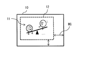
- FIG. 1A and FIG. 1B show two continuous captured images (original image 10) constituting a moving image in which camera shake occurs.
- original image 10) constituting a moving image in which camera shake occurs.
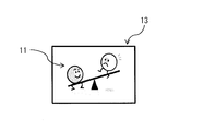
- FIGS. 1A and 1B when hand shake occurs, the position of the subject 11 on the original image 10 is shifted.
- the cutout region 12 to be moved is cut out according to the camera shake (the amount and direction of camera shake) obtained from the result.
- an image after electronic camera shake correction corrected image 13
- the size of the electronic camera shake margin MG is a parameter that determines the correction amount by the electronic camera shake correction.
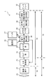
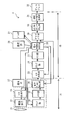
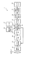
- FIG. 2A represents an example of functional blocks of the imaging device 1 according to an embodiment of the present disclosure.
- the imaging apparatus 1 includes an optical lens 21, an imaging element 22, an A / D conversion unit 23, a clamp unit 24, a memory unit 25, an electronic camera shake correction unit 26, a gyro 27, and a thermometer 28.
- the imaging apparatus 1 further includes a demosaic unit 29, an LM (linear matrix) / WB (white balance) / gamma correction unit 30, a luminance chroma signal generation unit 31, and a display 32.
- the imaging device 1 corresponds to a specific example of “imaging device” of the present disclosure.
- the image sensor 22 corresponds to a specific example of “image sensor” of the present disclosure.
- the electronic camera shake correction unit 26 corresponds to a specific example of a “first correction unit” of the present disclosure.
- the thermometer 28 corresponds to a specific example of the “detecting unit” of the present disclosure.
- one module 1A is configured by the optical lens 21 and the imaging element 22. Further, for example, an A / D conversion unit 23, a clamp unit 24, a memory unit 25, an electronic camera shake correction unit 26, a gyro 27, a thermometer 28, a demosaic unit 29, an LM / WB / gamma correction unit 30, and a luminance chroma signal generation unit. 31 constitutes one module 1B.
- one module 1C may be configured by the optical lens 21, the imaging element 22, and the A / D converter 23.
- the clamp unit 24, the memory unit 25, the electronic camera shake correction unit 26, the gyro 27, the thermometer 28, the demosaic unit 29, the LM / WB / gamma correction unit 30, and the luminance chroma signal generation unit 31 form one module 1D. May be configured.
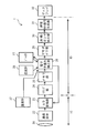
- the imaging device 1 may include an A / D conversion unit 33 as illustrated in FIG. 2B, for example.
- the optical lens 21, the imaging element 22, and the A / D conversion unit 33 constitute one module 1A.
- the A / D conversion unit 33 may be built in the image sensor 22. Further, for example, an A / D conversion unit 23, a clamp unit 24, a memory unit 25, an electronic camera shake correction unit 26, a gyro 27, a thermometer 28, a demosaic unit 29, an LM / WB / gamma correction unit 30, and a luminance chroma signal generation unit.
- One module 1 ⁇ / b> B may be configured by 31.
- both modules 1A and 1B are provided with an A / D conversion function, in actuality, either one of the A / D conversion unit 23 and the A / D conversion unit 33 is used. Only will be used.
- the electronic camera shake correction unit 26 may determine which of the A / D conversion unit 23 and the A / D conversion unit 33 to use based on the detection result of the thermometer 28. For example, when the temperature of the module 1B detected by the thermometer 28 is higher than a predetermined temperature, the electronic camera shake correction unit 26 stops the A / D conversion by the A / D conversion unit 23, and the A / D conversion The A / D conversion units 23 and 33 may be controlled so that the D conversion unit 33 starts A / D conversion.
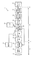
- the imaging apparatus 1 may include an A / D conversion unit 33, a clamp unit 34, a memory unit 35, and an electronic camera shake correction unit 36, for example, as illustrated in FIG. 2C.
- one module 1A is configured by the optical lens 21, the imaging element 22, the A / D conversion unit 33, the clamp unit 34, the memory unit 35, and the electronic camera shake correction unit 36.
- the A / D conversion unit 33, the clamp unit 34, the memory unit 35, and the electronic camera shake correction unit 36 may be built in the image sensor 22.
- both modules 1A and 1B are provided with an A / D conversion function and a camera shake correction function
- a set of A / D conversion unit 23 to electronic camera shake correction is performed. Only one of the unit 26 and the set of A / D conversion unit 33 to electronic camera shake correction unit 36 is used.
- the electronic camera shake correction unit 26 may determine which group is used for A / D conversion and electronic camera shake correction based on the detection result of the thermometer 28.
- the electronic camera shake correction unit 26 stops performing A / D conversion and electronic camera shake correction in the module 1B, and the module 1A
- the A / D converters 23 and 33 may be controlled to start A / D conversion and electronic camera shake correction.
- the imaging device 1 may include a thermometer 37 in addition to the thermometer 28 as shown in FIG. 2D, for example.
- the thermometer 37 may be mounted on the module 1C.
- both modules 1C and 1D are provided with a temperature measurement function, it is possible to perform control using the fact that the heat generation temperatures of the module 1C and the module 1D are different from each other. is assumed.
- the electronic camera shake correction unit 26 is one of the A / D conversion unit 23 and the electronic camera shake correction unit 26. Thus, it may be determined whether to reduce the amount of calculation related to electronic camera shake correction.
- the imaging apparatus 1 may include a thermometer 37 in addition to the thermometer 28 as shown in FIG. 2E, for example.
- the thermometer 37 may be mounted on the module 1A.
- both modules 1A and 1B are provided with a temperature measurement function, it is possible to perform control using the fact that the heat generation temperatures differ between module 1A and module 1B. is assumed.
- the electronic camera shake correction unit 26 is one of the A / D conversion unit 33 and the electronic camera shake correction unit 26. Thus, it may be determined whether to reduce the amount of calculation related to electronic camera shake correction.
- the electronic camera shake correction unit 26 uses the A / D conversion unit 23 and the A / D conversion unit based on the temperature of the module 1B detected by the thermometer 28 and the temperature of the module 1A detected by the thermometer 37. It may be determined which of 33 is used. For example, when the temperature of the module 1B detected by the thermometer 28 is higher than a predetermined temperature and the temperature of the module 1A detected by the thermometer 37 is lower than the predetermined temperature, the electronic camera shake correction unit 26 Even if the A / D conversion unit 23 is controlled so that the A / D conversion unit 23 stops the A / D conversion and the A / D conversion unit 33 starts the A / D conversion. Good.
- the imaging device 1 may include a thermometer 37 in addition to the thermometer 28 as shown in FIG. 2F, for example.
- the thermometer 37 may be mounted on the module 1A.
- both modules 1A and 1B are provided with a temperature measurement function, it is possible to perform control using the fact that the heat generation temperatures differ between module 1A and module 1B. is assumed.
- the electronic camera shake correction unit 26 Based on the temperature of the module 1 ⁇ / b> B detected by the thermometer 28 and the temperature of the module 1 ⁇ / b> A detected by the thermometer 37, the electronic camera shake correction unit 26 sets a set of A / D conversion units 23 to electronic camera shake correction units.
- a / D conversion unit 33 to electronic camera shake correction unit 36 may be used for A / D conversion and electronic camera shake correction.
- the electronic camera shake correction unit 26 A set of A / D converter 23 to electronic camera shake correction unit 26 stops A / D conversion and electronic camera shake correction, and a set of A / D conversion unit 33 to electronic camera shake correction unit 36 performs A / D conversion.
- the A / D converters 23 and 33 may be controlled so as to start the electronic camera shake correction.
- the imaging device 1 may include a thermometer 37 instead of the thermometer 28 as shown in FIG. 2G, for example.
- the thermometer 37 may be mounted on the module 1C.
- the electronic camera shake correction unit 26 determines which of the A / D conversion unit 23 and the electronic camera shake correction unit 26 should reduce the calculation amount related to the electronic camera shake correction. It may be.
- the imaging device 1 may include a thermometer 37 instead of the thermometer 28 as shown in FIG. 2H, for example.
- the thermometer 37 may be mounted on the module 1A.
- the electronic camera shake correction unit 26 determines which of the A / D conversion unit 33 and the electronic camera shake correction unit 26 should reduce the amount of calculation related to electronic camera shake correction. It may be. Further, the electronic camera shake correction unit 26 determines which one of the A / D conversion unit 23 and the A / D conversion unit 33 to use based on the temperature of the module 1A detected by the thermometer 37. Also good.
- the electronic camera shake correction unit 26 performs the A / D conversion by the A / D conversion unit 33.
- the A / D converters 23 and 33 may be controlled so that the A / D converter 23 starts and A / D conversion is started.
- the imaging apparatus 1 may include a thermometer 37 instead of the thermometer 28 as shown in FIG. 2I, for example.
- the thermometer 37 may be mounted on the module 1A.
- the electronic camera shake correction unit 26 sets a set of A / D conversion unit 23 to electronic camera shake correction unit 26 and a set of A / D conversion unit 33 to electronic camera shake. It may be determined which set of the correction unit 36 is used for A / D conversion and electronic camera shake correction.
- the electronic camera shake correction unit 26 uses the A / D conversion unit 33 to the electronic camera shake correction unit 36 to perform A / D.
- the A / D converters 23 and 33 are controlled so that the conversion and the electronic camera shake correction are stopped, and the A / D conversion and the electronic camera shake correction unit 26 start the A / D conversion and the electronic camera shake correction. You may come to do.
- the optical lens 21 adjusts the focal length of subject light incident on the image sensor 22.
- the specific configuration of the optical lens 21 is arbitrary.
- the optical lens 21 is composed of, for example, a plurality of lenses.
- the subject light transmitted through the optical lens 21 is incident on the image sensor 22 via, for example, an IR cut filter that transmits light other than infrared light.
- the image sensor 22 obtains a captured image (original image 10).
- the image sensor 22 outputs the obtained captured image (original image 10) to the A / D converters 23 and 33.
- the image sensor 22 converts subject light into an electrical signal in units of pixels and supplies the electrical signal to the A / D converters 23 and 33.
- the imaging element 22 has, for example, a pixel array unit composed of a plurality of imaging pixels arranged in a matrix on a silicon substrate, and a peripheral circuit unit that drives the pixel array unit.
- Each imaging pixel has, for example, a photodiode as a photoelectric conversion element and a plurality of pixel transistors (so-called MOS transistors).
- the A / D converters 23 and 33 convert the RGB electrical signals (analog signals) (that is, the captured image (original image 10)) supplied from the image sensor 22 into digital data (pixel data).
- the A / D conversion units 23 and 33 supply the digital pixel data (RAW data) to the clamp units 24 and 34.
- the clamp units 24 and 34 subtract the black level, which is a level determined as black, from the pixel data output from the A / D conversion units 23 and 34.
- the clamp units 24 and 34 output the pixel data (pixel value) memory units 25 and 35 after the black level subtraction.
- the memory units 25 and 35 temporarily store the pixel data from the clamp units 24 and 34.
- the gyro 27 detects the displacement / rotation of the imaging device 1.
- the gyro 27 detects the displacement / rotation of the imaging device 1 continuously or at a predetermined sampling cycle, and outputs the detection result to the electronic camera shake correction unit 26.
- the thermometers 28 and 37 detect the temperature in the imaging device 1.
- the thermometers 28 and 37 detect the temperature in the imaging apparatus 1 continuously or at a predetermined sampling period, and output the detection result to the electronic camera shake correction unit 26.
- the thermometer 28 detects the temperature of the A / D conversion unit 23 or the electronic camera shake correction unit 26.
- the thermometer 37 detects the temperature of the A / D conversion unit 33 or the electronic camera shake correction unit 36.
- the demosaic unit 29 performs demosaic processing on the pixel data from the electronic camera shake correction unit 26, performs color information complementation, etc., and converts it into RGB data.
- the demosaic unit 29 supplies the image data after demosaic processing to the LM / WB / gamma correction unit 30.
- the LM / WB / gamma correction unit 30 corrects color characteristics of the image data from the demosaic unit 29. Specifically, the LM / WB / gamma correction unit 30 uses the matrix coefficient to fill the image data in order to fill the difference between the chromaticity point of the primary color (RGB) and the actual chromaticity point of the camera. Each color signal is corrected to change the color reproducibility.
- the LM / WB / gamma correction unit 30 adjusts the white balance by setting a gain for white for each channel value of the image data. Further, the LM / WB / gamma correction unit 30 performs gamma correction to obtain a display closer to the original by adjusting the relative relationship between the color of the image data and the output device characteristics. The LM / WB / gamma correction unit 30 supplies the corrected image data to the luminance chroma signal generation unit 31.
- the luminance chroma signal generation unit 31 generates a luminance signal (Y) and color difference signals (Cr, Cb) from the image data supplied from the LM / WB / gamma correction unit 30.
- the luminance chroma signal generation unit 31 generates the luminance chroma signal (Y, Cr, Cb)
- the luminance chroma signal and the color difference signal are supplied to the display 32.
- the display 32 displays an image based on the image data (luminance chroma signal) supplied from the luminance chroma signal generation unit 31. In other words, the display 32 displays a moving image or a still image captured by the image sensor 22.
- the display 32 includes, for example, an LCD (Liquid Crystal Display) or an organic EL (Electro Luminescence) display.
- the electronic camera shake correction unit 26 is based on the detection result of at least one of the thermometer 28 and the thermometer 37, and the captured image (original image) obtained by the imaging device 22 when the electronic camera shake correction function is enabled.
- the electronic camera shake correction accuracy with respect to 10) is changed.
- the original image 10 corresponds to a specific example of “captured image” of the present disclosure.
- “The electronic camera shake correction function is effective” means that electronic camera shake correction is being performed or electronic camera shake correction is to be performed, and whether or not the electronic camera shake correction effect is effective. Not pointing at.
- “Electronic camera shake correction accuracy” refers to, for example, a subject in a plurality of corrected images 13 obtained by performing electronic camera shake correction on a plurality of captured images (original image 10) that are continuously captured. 11 is a concept related to the fluctuation of position 11.
- the electronic camera shake correction accuracy has a correlation with the size of the camera shake correction margin MG.
- the cutout region 12 can be largely shifted in the captured image (original image 10) by the amount of the camera shake correction margin MG being large. Therefore, when the camera shake correction margin MG is large, the electronic camera shake correction accuracy can be increased.
- the amount of calculation required for camera shake correction increases as the camera shake correction margin MG is larger.
- the amount of calculation has a correlation with the amount of power consumption, and also has a correlation with the amount of heat generated by the modules 1A to 1D caused by the power consumption. Therefore, when the camera shake correction margin MG is large, the power consumption is large, and the heat generation amount of the modules 1A to 1D is also large.
- the maximum value of the amount by which the cutout region 12 is shifted in the captured image (original image 10) is also reduced by the amount that the camera shake correction margin MG is small.
- the amount by which the cutout region 12 is shifted in the captured image (original image 10) may fall within the camera shake correction margin MG.
- the shift amount may not be within the camera shake correction margin MG, and the shift amount may be limited. In this case, it is difficult to completely eliminate camera shake by electronic camera shake correction. Therefore, when the camera shake correction margin MG is small, the electronic camera shake correction accuracy tends to be low.
- the camera shake correction margin MG is small, the amount of calculation required for camera shake correction is reduced. Therefore, when the camera shake correction margin MG is small, the power consumption is small, and the heat generation amount of the modules 1A to 1D is also small.
- the electronic camera shake correction units 26 and 36 may use the camera shake correction margin MG as a variable parameter for changing the power consumption amount and the heat generation amount of the modules 1A to 1D.
- the electronic camera shake correction units 26 and 36 change the size of the camera shake correction margin MG when the region including the subject 11 is cut out from the captured image (original image 10) based on the detection result of the thermometer 28. May be.
- the electronic camera shake correction unit 36 may be configured to receive the detection result of the thermometer 28 directly from the thermometer 28 or through the electronic camera shake correction unit 26 as shown in FIG. 2C. May be.
- the electronic camera shake correction unit 26 corrects camera shake when the region including the subject 11 is cut out from the captured image (original image 10) based on the detection results of the thermometer 28 and the thermometer 37.
- the size of the margin MG may be changed.
- the electronic camera shake correction units 26 and 36 determine the camera shake correction margin MG when the region including the subject 11 is extracted from the captured image (original image 10) based on the detection results of the thermometer 28 and the thermometer 37. You may change the size.
- the electronic camera shake correction unit 36 may be configured to receive the detection result of the thermometer 28 directly from the thermometer 28 or through the electronic camera shake correction unit 26 as shown in FIG. 2F. May be.
- the electronic camera shake correction units 26 and 36 change the size of the camera shake correction margin MG when the region including the subject 11 is cut out from the captured image (original image 10) based on the detection result of the thermometer 37. May be.
- the electronic camera shake correction unit 36 may be configured to receive the detection result of the thermometer 37 directly from the thermometer 28 or through the electronic camera shake correction unit 26 as shown in FIG. 2I. May be.
- the electronic camera shake correction unit 26 may change the number of pixels of the captured image (original image 10) based on the detection result of the thermometer 28 in FIGS. 2A and 2B.
- the electronic camera shake correction units 26 and 36 may change the number of pixels of the captured image (original image 10) based on the detection result of the thermometer 28 in FIG. 2C.
- the electronic camera shake correction unit 26 may change the number of pixels of the captured image (original image 10) based on the detection results of the thermometer 28 and the thermometer 37 in FIGS. 2D and 2E.
- the electronic camera shake correction units 26 and 36 may change the number of pixels of the captured image (original image 10) based on the detection results of the thermometer 28 and the thermometer 37 in FIG. 2F. Moreover, the electronic camera shake correction unit 26 may change the number of pixels of the captured image (original image 10) based on the detection result of the thermometer 37 in FIGS. 2G and 2H. In addition, the electronic camera shake correction units 26 and 36 may change the number of pixels of the captured image (original image 10) based on the detection result of the thermometer 37 in FIG. 2I.
- FIG. 3A, 3B, and 3C illustrate an example of an electronic camera shake correction algorithm in the imaging apparatus 1.
- FIG. 3A, FIG. 3B, and FIG. 3C illustrate an example of an electronic camera shake correction algorithm in the imaging apparatus 1.
- FIG. 3A, FIG. 3B, and FIG. 3C illustrate an example of an electronic camera shake correction algorithm in the imaging apparatus 1.
- FIG. 3A, FIG. 3B, and FIG. 3C illustrate an example of an electronic camera shake correction algorithm in the imaging apparatus 1.
- FIG. 3A illustrates an example of the camera shake correction margin MG when the temperature is low, and illustrates a state in which the camera shake correction margin MG is provided about 10% around the cutout region 12.
- FIG. 3C illustrates an example of the camera shake correction margin MG when the temperature is high, and illustrates a state in which the camera shake correction margin MG is provided about 5% around the cutout region 12.
- FIG. 3B shows an example of a camera shake correction margin MG when the temperature is an intermediate temperature between FIGS. 3A and 3
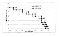
- FIG. 4 is a graph showing an example of an algorithm for electronic camera shake correction in the imaging apparatus 1.
- the electronic camera shake correction units 26 and 36 decrease the camera shake correction margin MG intermittently (stepwise) as the temperature rises and intermittently (stepwise) as the temperature falls.
- the electronic camera shake correction units 26 and 36 change the threshold value for changing the camera shake correction margin MG between when the temperature is rising and when the temperature is decreasing. This prevents the camera shake correction margin MG from frequently switching when the detected temperature oscillates in the vicinity of the threshold for changing the camera shake correction margin MG.
- the electronic camera shake correction units 26 and 36 obtain the temperature used for the determination of switching of the camera shake correction margin MG from at least one of the thermometer 28 and the thermometer 37.
- the electronic camera shake correction units 26 and 36 include a temperature rise table describing the relationship between the temperature and the camera shake correction margin MG when the temperature rises, and a temperature drop describing the relationship between the temperature and the camera shake correction margin MG when the temperature falls. And a table.
- the electronic camera shake correction units 26 and 36 may have various setting data related to the electronic camera shake correction accuracy for each size of the camera shake correction margin MG.
- Examples of various setting data related to electronic camera shake correction accuracy include, for example, “ID of A / D converter to be used (ID of A / D converter 23 or A / D converter 33)” or “ Data relating to the “number of pixels of the captured image (original image 10)”, “A / D conversion area” described later, and “Electronic image stabilization frequency” described later are included.
- the electronic camera shake correction units 26 and 36 obtain various setting data corresponding to the size of the camera shake correction margin MG, and an imaging apparatus that requires the setting data. It may be provided to devices within one.
- the electronic camera shake correction units 26 and 36 may turn off the electronic camera shake correction when the camera shake correction margin MG falls below a certain value.
- the imaging element 22 changes the number of pixels based on the detection result of at least one of the thermometer 28 and the thermometer 37. It is conceivable to output a captured image (original image 10).
- the A / D converter 23 or the A / D converter 33 detects at least one of the thermometer 28 and the thermometer 37. Based on the result, an area for A / D conversion may be determined in the captured image (original image 10).
- the A / D conversion unit 23 or the A / D conversion unit 33 determines the size of the A / D conversion region in the captured image (original image 10) based on the detection result of at least one of the thermometer 28 and the thermometer 37. You may change the height.
- the A / D conversion unit 23 or the A / D conversion unit 33 may acquire temperature information directly from at least one of the thermometer 28 and the thermometer 37, or via the electronic camera shake correction unit 26. Temperature information may be acquired.
- the A / D conversion unit 23 or the A / D conversion unit 33 may perform A / D conversion only on pixel data corresponding to a region where A / D conversion is performed in the captured image (original image 10). .
- the electronic camera shake correction unit 26 or the electronic camera shake correction unit 36 may perform the determination of the area for A / D conversion in the captured image (original image 10). That is, based on the detection result of at least one of the thermometer 28 and the thermometer 37, the electronic camera shake correction unit 26 or the electronic camera shake correction unit 36 selects an area for A / D conversion in the captured image (original image 10). The control signal corresponding to the determined area may be output to the A / D converter 23 or the A / D converter 33.
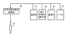
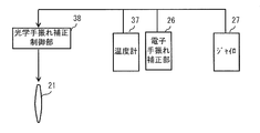
- the imaging apparatus 1 may include an optical camera shake correction control unit 38 as illustrated in FIGS. 5A, 5B, and 5C, for example.
- the optical camera shake correction control unit 38 is for performing camera shake correction using the optical lens 21, and displaces the optical lens 21 based on displacement / rotation information from the gyro 27.
- the optical camera shake correction control unit 38 is built in the module 1A or the module 1C.
- the optical camera shake correction control unit 38 controls on / off of the optical camera shake correction based on the detection result obtained from at least one of the thermometer 28 and the thermometer 37.
- the electronic camera shake correction unit 26 stops the electronic camera shake correction in the electronic camera shake correction unit 26, and the optical camera shake
- the optical camera shake correction control unit 38 may be controlled to start the optical camera shake correction in the correction control unit 38 (see FIG. 5A).
- the electronic camera shake correction unit 26 stops the optical camera shake so as to stop the optical camera shake correction in the optical camera shake correction control unit 38.
- the correction controller 38 may be controlled so that the electronic camera shake correction unit 26 starts the electronic camera shake correction (see FIG. 5A).
- the electronic The camera shake correction unit 26 stops the electronic camera shake correction in the electronic camera shake correction unit 26 and controls the optical camera shake correction control unit 38 so as to start the optical camera shake correction in the optical camera shake correction control unit 38. Good (see FIG. 5B).
- the electronic The camera shake correction unit 26 may control the optical camera shake correction control unit 38 so as to stop the optical camera shake correction in the optical camera shake correction control unit 38, and the electronic camera shake correction unit 26 may start the electronic camera shake correction (FIG. 5B).
- the optical camera shake correction control unit 38 is controlled so as to stop the optical camera shake correction in the optical camera shake correction control unit 38.
- the electronic camera shake correction unit 26 may start electronic camera shake correction (see FIG. 5C).
- the electronic camera shake correction unit 26 performs optical camera shake correction in the electronic camera shake correction unit 26.
- the optical camera shake correction control unit 38 may be controlled so that the optical camera shake correction control unit 38 starts the optical camera shake correction (see FIG. 5C).
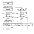
- FIG. 6 illustrates an example of a procedure for electronic camera shake correction in the imaging apparatus 1.
- the user activates the imaging device 1 (step S101). Then, the imaging apparatus 1 starts up not only the shooting function but also the camera shake correction function (step S102). Subsequently, the electronic camera shake correction unit 26 continuously or intermittently obtains the temperature detection result from the thermometer 28 or the thermometer 37 (step S103), and determines whether or not the temperature change is in the temperature rising phase. (Step S104). As a result, when the temperature change is a temperature rising phase, the electronic camera shake correction unit 26 determines whether the temperature is 50 ° C. or higher based on the already detected temperature detection result (step S105). . As a result, when the temperature is 50 ° C. or higher, the electronic camera shake correction unit 26 determines whether the temperature is 60 ° C.
- the electronic camera shake correction unit 26 selects, for example, 5% as the camera shake correction margin MG (step S107). At this time, the electronic camera shake correction unit 26 provides, for example, various setting data corresponding to the camera shake correction margin MG5% to a device in the imaging apparatus 1 that needs it. The imaging apparatus 1 continues shooting using the table and setting data provided by the electronic camera shake correction unit 26 (step S108).
- step S104 when the temperature change is not in the temperature rising phase, the electronic camera shake correction unit 26 determines whether the temperature change is in the temperature falling phase based on the already detected temperature detection result (step S104). S109). As a result, when the temperature change is in the temperature decreasing phase, the electronic camera shake correction unit 26 determines whether the temperature is 58 degrees or less based on the already detected temperature detection result (step S110). . As a result, when the temperature is not below 58 degrees, the electronic camera shake correction unit 26 selects, for example, 8% as the camera shake correction margin MG (step S111). At this time, the electronic camera shake correction unit 26 provides, for example, various setting data corresponding to the camera shake correction margin MG8% to a device in the imaging apparatus 1 that needs the setting data. The imaging apparatus 1 continues shooting using the table and setting data provided by the electronic camera shake correction unit 26 (step S108).
- step S110 when the temperature is equal to or lower than 58 degrees, the electronic camera shake correction unit 26 determines whether the temperature is equal to or lower than 48 degrees based on the already detected temperature detection result (step S112). Similarly, in step S105, when the temperature is not 50 ° C. or higher, the electronic camera shake correction unit 26 determines whether the temperature is 48 ° C. or lower based on the already acquired detection result regarding the temperature ( Step S112). As a result, when the temperature is 48 degrees or less, the electronic camera shake correction unit 26 selects, for example, 10% as the camera shake correction margin MG (step S113). At this time, the electronic camera shake correction unit 26 provides, for example, various setting data corresponding to the camera shake correction margin MG10% to a device in the imaging apparatus 1 that requires the setting data.
- step S106 when the temperature is not 60 degrees or higher, the electronic camera shake correction unit 26 selects, for example, 8% as the camera shake correction margin MG (step S111). At this time, the electronic camera shake correction unit 26 provides, for example, various setting data corresponding to the camera shake correction margin MG8% to a device in the imaging apparatus 1 that needs the setting data. The imaging apparatus 1 continues shooting using the table and setting data provided by the electronic camera shake correction unit 26 (step S108).
- step S112 when the temperature is not 48 degrees or less, the electronic camera shake correction unit 26 selects, for example, 10% as the camera shake correction margin MG (step S113). At this time, the electronic camera shake correction unit 26 provides, for example, various setting data corresponding to the camera shake correction margin MG10% to a device in the imaging apparatus 1 that requires the setting data. The imaging apparatus 1 continues shooting using the table and setting data provided by the electronic camera shake correction unit 26 (step S108).
- the electronic camera shake correction unit 26 performs selection based on the detection results (temperature data) obtained from the two thermometers 28 and 37. Also good. Such a selection is particularly effective when a device equivalent to a device included in the module having the higher temperature is provided in the module having the lower temperature.
- the module 1A may be provided with an A / D converter 33
- the module 1B may be provided with an A / D converter 23.
- the A / D conversion unit 33 may be built in the image sensor 22.
- the electronic camera shake correction unit 26 determines which of the A / D conversion unit 23 and the A / D conversion unit 33 to use based on the detection result obtained from at least one of the thermometer 28 and the thermometer 37. May be.
- the electronic camera shake correction unit 26 controls the A / D conversion units 23 and 33 so as to stop using the A / D conversion unit 23 and start using the A / D conversion unit 33. Also good.
- the module 1A may be provided with an A / D conversion unit 33 to an electronic camera shake correction unit 36
- the module 1B may be provided with an A / D conversion unit 23 to an electronic camera shake correction unit 26.
- the A / D conversion unit 33 to the electronic camera shake correction unit 36 may be built in the image sensor 22.
- the electronic camera shake correction unit 26 stops using the A / D conversion unit 23 to the electronic camera shake correction unit 26 and starts using the A / D conversion unit 33 to the electronic camera shake correction unit 36.
- the A / D converters 23 and 33 may be controlled.
- the optical camera shake correction control unit 38 may be provided in the module 1A, and the electronic camera shake correction unit 26 may be provided in the module 1B.
- the electronic camera shake correction unit 26 determines whether or not to perform the optical camera shake correction instead of the electronic camera shake correction. Also good.
- the electronic camera shake correction unit 26 may stop the electronic camera shake correction after instructing the optical camera shake correction control unit 38 to perform the optical camera shake correction.
- the electronic camera shake correction unit 26 may switch from electronic camera shake correction to optical camera shake correction when the camera shake correction margin MG falls below a certain value.
- the optical camera shake correction control unit 38 may perform optical camera shake correction using the optical lens 21 immediately after receiving an instruction to perform optical camera shake correction from the electronic camera shake correction unit 26.
- the captured image obtained by the imaging element 22 when the electronic camera shake correction function is enabled ( The electronic shake correction accuracy for the original image 10) can be changed.
- the size of the camera shake correction margin MG when the region including the subject 11 is cut out from the captured image (original image 10) is changed.
- the electronic camera shake correction accuracy is gradually increased according to the temperature magnitude or the temperature change in the imaging apparatus 1 without suddenly turning off or turning on the electronic camera shake correction. To change. Thereby, a natural user experience can be given compared with the case where electronic camera shake correction is suddenly turned off or turned on.
- the “electronic camera shake correction accuracy” is defined as a concept related to the fluctuation of the position of the subject 11 in the plurality of corrected images 13.
- the sensation of electronic camera shake correction accuracy may change only by changing the electronic camera shake correction frequency (the number of electronic camera shake correction per unit time in a moving image). Therefore, strictly speaking, the “electronic camera shake correction accuracy” is not only the fluctuation of the position of the subject 11 in the plurality of corrected images 13 but also the electronic camera shake correction frequency (the number of electronic camera shake correction per unit time in a moving image). Is also a related concept.
- the electronic camera shake correction unit 26 includes at least one of the thermometer 28 and the thermometer 37 as shown in FIGS. 7A, 7B, and 7C, for example. Based on the detection result, the electronic camera shake correction frequency is changed.
- the electronic camera shake correction unit 26 decreases the electronic camera shake correction frequency as the temperature rises, and increases the electronic camera shake correction frequency as the temperature decreases.
- the electronic camera shake correction unit 26 preferably varies the threshold value for changing the electronic camera shake correction frequency between when the temperature rises and when the temperature falls.
- the electronic camera shake correction unit 26 further outputs a sampling period or a detection result of at least one of the gyro 27 and the thermometers 28 and 34 based on the detection result of at least one of the thermometer 28 and the thermometer 37.
- the period may be changed.
- the electronic camera shake correction unit 26 generates a control signal related to the sampling period or the output period of the detection result based on the detection result of at least one of the thermometer 28 and the thermometer 37, and the generated control signal is You may output to at least one among the gyro 27 and the thermometers 28 and 34.
- the gyro 27 may change the sampling period or the detection result output period based on a control signal related to the sampling period or the detection result output period input from the electronic camera shake correction unit 26.
- the thermometers 28 and 34 change the sampling period or the detection result output period based on the control signal related to the sampling period or the detection result output period input from the electronic camera shake correction unit 26. Also good.
- the electronic camera shake correction unit 26 may control at least one of the gyro 27 and the thermometers 28 and 34 so that the sampling cycle or the output cycle of the detection result becomes longer as the temperature rises. Further, the electronic camera shake correction unit 26 may control at least one of the gyro 27 and the thermometers 28 and 34 so that the sampling period or the output period of the detection result is shortened as the temperature decreases. Good.
- the electronic camera shake correction frequency is changed based on the detection result of at least one of the thermometer 28 and the thermometer 37.
- a natural user experience can be given compared with the case where electronic camera shake correction is suddenly turned off or turned on.
- the power consumption amount and the heat generation amount of the modules 1A, 1B, 1C, and 1D can be changed with the change of the electronic camera shake correction frequency.
- the sampling period or the output of the detection result is output to at least one of the gyro 27 and the thermometers 28 and 34.
- the power consumption and the heat generation amount of the modules 1A, 1B, 1C, 1D can be changed.
- the imaging apparatus 1 described above includes, for example, a digital still camera, a video camera, a portable terminal such as a smartphone (multi-function mobile phone) having an imaging function, a capsule endoscope, a spectacle-type imaging apparatus in which an imaging function is added to glasses, and the like. It can be applied to all electronic devices. Below, the specific example of the electronic device to which the imaging device 1 is applied is demonstrated. The electronic device corresponds to a specific example of “electronic device” of the present disclosure.
- FIG. 8A shows configuration examples in which the electronic circuit portion of the imaging device 1 is formed in a chip form.
- the imaging device 330 illustrated in FIG. 8A includes, for example, a pixel region 332 including the pixel array unit in the above-described imaging device 22 and a peripheral circuit unit in the above-described imaging device 22 in one semiconductor chip unit 331.
- a control circuit 333 that supplies a control signal to the area 332 and a logic circuit 334 including the above-described A / D conversion unit 23 and electronic camera shake correction unit 26 are configured.
- the imaging device 340 shown in FIG. 8B includes a semiconductor chip part 341 and a semiconductor chip part 342.
- the semiconductor chip unit 341 includes a pixel region 343 including the pixel array unit in the image sensor 22 described above, and a control circuit 344 that includes the peripheral circuit unit in the image sensor 22 described above and supplies a control signal to the pixel region 332. Is done.
- the semiconductor chip unit 342 includes a logic circuit 345 including the above-described A / D conversion unit 23, A / D conversion unit 33, electronic camera shake correction unit 26, electronic camera shake correction unit 36, and the like. Then, the semiconductor chip unit 341 and the semiconductor chip unit 342 are electrically connected to each other, whereby the imaging device 340 as one semiconductor chip is configured. That is, the A / D conversion unit 23, the A / D conversion unit 33, the electronic camera shake correction unit 26, or the electronic camera shake correction unit 36 is provided in the logic circuit 345 stacked on the semiconductor chip unit 341 (the image sensor 22). Yes.
- the imaging device 350 shown in FIG. 8C includes a semiconductor chip portion 351 and a semiconductor chip portion 352.
- the semiconductor chip unit 351 is configured to include a pixel region 353 including the pixel array unit in the imaging element 22 described above.
- the semiconductor chip unit 352 includes a peripheral circuit unit in the image sensor 22 described above, and includes a control circuit 354 that supplies a control signal to the pixel region 332, an A / D conversion unit 23, an A / D conversion unit 33, and an electronic image stabilization unit. 26, or a logic circuit 355 including an electronic camera shake correction unit 36 and the like.
- the A / D conversion unit 23, the A / D conversion unit 33, the electronic camera shake correction unit 26, or the electronic camera shake correction unit 36 is provided in the logic circuit 355 stacked on the semiconductor chip unit 351 (the image sensor 22). Yes.
- the semiconductor chip unit 351 and the semiconductor chip unit 352 are electrically connected to each other, whereby the imaging device 350 as one semiconductor chip is configured.
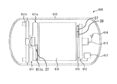
- FIG. 9 shows a cross-sectional configuration example of a capsule endoscope 600 on which the imaging device 1 is mounted.
- a capsule endoscope 600 shown in FIG. 9 has, for example, a camera (ultra-small camera) 611 and a camera 611 for capturing an image of a body cavity in a case 610 having hemispherical end faces and a cylindrical center part.
- Wireless for transmitting the recorded image data to the outside via the antenna 614 after the capsule endoscope 600 is discharged out of the body of the subject.
- a transmitter 613 is provided.
- thermometer 28 controls photographing by the camera 611 and data storage operation in the memory 612, and controls data transmission from the memory 612 to a data receiving device (not shown) outside the housing 610 by the wireless transmitter 613.
- the coil 616 supplies power to the camera 611, the memory 612, the wireless transmitter 613, the antenna 614, and a light source 611b described later.
- the thermometer 28 is disposed in the vicinity of the CPU 615.
- the thermometer 37 is disposed in the vicinity of the camera 611 (a processing unit 611c described later).
- the casing 610 is provided with a reed (magnetic) switch 617 for detecting when the capsule endoscope 600 is set in the data receiving apparatus.
- a reed switch 617 detects the setting to the data receiving device and data transmission becomes possible, the power supply from the coil 616 to the wireless transmitter 613 is started.
- the camera 611 is obtained by, for example, a solid-state image sensor 611a including an objective optical system for taking an image of a body cavity, a plurality of (here, two) light sources 611b that illuminate the body cavity, and the solid-state image sensor 611a.
- a processing unit 611c for processing data.
- the light source 611b is configured by, for example, an LED (Light Emitting Diode).
- the image sensor 611a includes the image sensor 22 and the optical lens 21 shown in FIG.
- the image sensor 611a is configured to further include an optical camera shake correction control unit 33 as necessary.
- the CPU 615 performs control corresponding to the electronic camera shake correction unit 26 of FIG.
- the processing unit 611c may include an A / D conversion unit 33 or an A / D conversion unit 33 to an electronic camera shake correction unit 36.
- FIG. 10A shows an external configuration of a smartphone 500 equipped with the imaging device 1.
- the smartphone 500 includes a speaker 511, a display 512, operation buttons 513, a microphone 514, an imaging unit 515, and the like.
- the smartphone 500 performs a telephone function
- the transmitted voice acquired from the microphone 514 is transmitted to the base station via the communication unit (not shown), and the received voice from the other party is transmitted from the communication unit to the speaker 511. The sound is supplied and reproduced.
- the display 512 is composed of an LCD (Liquid Crystal Display), for example, and displays a predetermined screen such as a telephone standby screen.
- a touch panel is superimposed on the display 512, and an operation input to the display 512 by a user's finger or the like can be detected.
- the smartphone 500 can perform predetermined processing, for example, execution of a photographing function, according to the detected user operation input.
- the imaging unit 515 includes an imaging element 22 and an optical lens 21. The imaging unit 515, for example, images a subject and stores image data obtained as a result in an internal memory or the like.
- the imaging unit 515 may further include an optical camera shake correction control unit 33.
- the imaging unit 515 may further include an A / D conversion unit 23.
- the imaging unit 515 may further include a thermometer 28 as illustrated in FIG. 10B, for example. .
- the thermometer 28 is included in the imaging unit 515, the thermometer 28 is disposed at least adjacent to the imaging element 22 and the A / D conversion unit 23. Therefore, in this case, the thermometer 28 mainly measures the temperature of the image sensor 22 and the A / D converter 23.
- the electronic camera shake correction unit 26 includes the thermometer 28 in the imaging unit 515. It is preferable that camera shake correction is performed based on the detection result.
- the smartphone 500 includes an electronic circuit 516 that controls a speaker 511, a display 512, operation buttons 513, a microphone 514, an imaging unit 515, and the like, as shown in FIG. 10C.
- the smartphone 500 further includes a gyro 27.
- the electronic circuit 516 may further include an A / D conversion unit 23 to an electronic camera shake correction unit 26, and a demosaic unit 29 to a luminance chroma signal correction unit 31.
- the thermometer 28 may be provided adjacent to the electronic circuit 516 instead of the imaging unit 515.
- the thermometer 28 mainly measures the temperature of the electronic camera shake correction unit 26 and the A / D conversion unit 23.
- the thermometer 28 may be disposed on the substrate of the electronic circuit 516.
- thermometer 28 When the thermometer 28 is provided adjacent to the electronic circuit 516 to measure the temperature of the electronic camera shake correction unit 26 and the A / D conversion unit 23, the electronic camera shake correction unit 26 is included in the electronic circuit 516. It is preferable that camera shake correction is performed based on the detection result of the thermometer 28.
- the smartphone 500 may include the thermometer 28 adjacent to the electronic circuit 516 and may include the thermometer 37 in the imaging unit 515.
- the electronic camera shake correction unit 26 detects the detection result obtained from the thermometer 37 (the temperature of the imaging unit 515). ) And the detection result (temperature of the electronic circuit 516) obtained from the thermometer 28, it is possible to perform camera shake correction.
- the temperature of the imaging unit 515 is higher than that of the electronic circuit 516.
- the electronic camera shake correction unit 26 stops the A / D conversion by the A / D conversion unit 23 in the electronic circuit 516, and the A / D conversion unit 33 in the imaging unit 515. In this case, A / D conversion may be performed. Further, as a result of comparing the detection result obtained from the thermometer 37 (temperature of the imaging unit 515) with the detection result obtained from the thermometer 28 (temperature of the electronic circuit 516), the temperature of the electronic circuit 516 is imaged.
- the electronic camera shake correction unit 26 stops the A / D conversion by the A / D conversion unit 33 in the imaging unit 515, and performs the A / D conversion in the electronic circuit 516.
- the unit 23 may perform A / D conversion.
- the smartphone 500 may further include an A / D conversion unit 33 to an electronic camera shake correction unit 36 in the imaging unit 515 in the smartphone 500 illustrated in FIG. 10D.
- the electronic camera shake correction unit 26 detects the detection result obtained from the thermometer 28 (the temperature of the imaging unit 515). ) And the detection result (temperature of the electronic circuit 516) obtained from the thermometer 28, it is possible to perform camera shake correction.
- the temperature of the imaging unit 515 is higher than that of the electronic circuit 516.
- the electronic camera shake correction unit 26 stops the A / D conversion and the electronic camera shake correction by the A / D conversion unit 23 to the electronic camera shake correction unit 26 in the electronic circuit 516, and performs imaging.
- a / D conversion and electronic camera shake correction may be performed by the A / D conversion unit 33 to the electronic camera shake correction unit 36 in the unit 515.
- the temperature of the electronic circuit 516 is imaged.
- the electronic camera shake correction unit 26 stops the A / D conversion and the electronic camera shake correction unit 36 in the imaging unit 515 from performing A / D conversion and electronic camera shake correction.
- the A / D conversion and the electronic camera shake correction unit 26 in the electronic circuit 516 may perform A / D conversion and electronic camera shake correction.
- FIG. 11 shows a configuration example of a glasses-type imaging device 400 equipped with the imaging device 1.
- An eyeglass-type imaging device 400 in FIG. 11 includes a housing 414 in which an image sensor 412 attached to the center of a frame 411 and an eyeglass lens 413 are fixed and an image signal processing circuit for driving and controlling the image sensor 412 is incorporated.
- the image sensor 412 includes the image sensor 22.
- the eyeglass-type imaging device 400 includes an image signal processing circuit having control functions such as an A / D conversion unit 23 to an electronic camera shake correction unit 26 and a demosaic unit 29 to a luminance chroma signal generation unit 31 in a housing 414.
- the image signal processing circuit in the housing 414 further includes a gyro 27 and a thermometer 28.
- the thermometer 28 is disposed adjacent to the A / D conversion unit 23 and the electronic camera shake correction unit 26 in the housing 414. Therefore, the thermometer 28 measures the temperature of the A / D conversion unit 23 and the electronic camera shake correction unit 26 in the housing 414.
- Image data captured by the image sensor 412 is transmitted to an external circuit via the communication cable 415.
- the eyeglass-type imaging device 400 may have a wireless communication function and transmit image data by wireless communication. Further, an image photographed by the image sensor 412 may be projected onto the eyeglass lens 413.
- the eyeglass-type imaging device 400 may include the thermometer 28 adjacent to the image signal processing circuit in the housing 414 and may include the thermometer 37 adjacent to the imaging element 412.
- the electronic camera shake correction unit 26 detects the detection result obtained from the thermometer 37 (temperature of the image sensor 412). Based on the detection result obtained from the thermometer 28 (temperature of the image signal processing circuit in the housing 414), it is possible to perform camera shake correction.
- the temperature of the image sensor 412 is obtained.
- the electronic camera shake correction unit 26 performs A / D conversion at the A / D conversion unit 23 included in the image signal processing circuit in the housing 414. The conversion may be stopped, and the A / D conversion may be performed by the A / D conversion unit 33 adjacent to the image sensor 412.
- the inside of the housing 414 is obtained.
- the electronic camera shake correction unit 26 performs A / D conversion by the A / D conversion unit 33 adjacent to the image sensor 412. May be stopped, and A / D conversion may be performed by the A / D conversion unit 23 included in the image signal processing circuit in the housing 414.
- the eyeglass-type imaging device 400 may further include an A / D conversion unit 33 to an electronic camera shake correction unit 36 adjacent to the imaging device 412.
- the electronic camera shake correction unit 26 detects the detection result obtained from the thermometer 37 (temperature of the image sensor 412). Based on the detection result obtained from the thermometer 28 (temperature of the image signal processing circuit in the housing 414), it is possible to perform camera shake correction.
- the temperature of the imaging unit 412 is obtained.
- the electronic camera shake correction unit 26 corrects the A / D conversion unit 23 to the electronic camera shake correction included in the image signal processing circuit in the housing 414.
- the A / D conversion and electronic camera shake correction are stopped by the unit 26, and the A / D conversion and electronic camera shake correction are performed by the A / D conversion unit 33 to the electronic camera shake correction unit 36 adjacent to the imaging unit 412. Also good.
- the electronic camera shake correction unit 26 uses the A / D conversion unit 33 to the electronic camera shake correction unit 36 adjacent to the imaging unit 412 to perform A / D conversion and electronic camera shake correction are stopped, and A / D conversion and electronic camera shake correction are performed by the A / D conversion unit 23 to the electronic camera shake correction unit 26 included in the image signal processing circuit in the housing 414. It may be.
- the imaging device 1 may include a detection unit (battery level meter 39) that detects the remaining battery level instead of the thermometers 28 and 37 (see FIG. 12).
- the battery fuel gauge 39 detects the output voltage of the battery.
- the battery fuel gauge 39 outputs the detected output voltage to the electronic camera shake correction units 26 and 36.
- the battery level meter 39 may output the detected output voltage to the electronic camera shake correction units 26 and 36 after converting the detected output voltage into the battery level.
- the electronic camera shake correction units 26 and 36 decrease the camera shake correction margin MG intermittently (stepwise) as the temperature rises and intermittently (stepwise) as the temperature falls.
- the electronic camera shake correction units 26 and 36 change the threshold value for changing the camera shake correction margin MG between when the power supply voltage is increased and when the power supply voltage is decreased. This prevents frequent switching of the camera shake correction margin MG when the detected remaining amount oscillates in the vicinity of the threshold value for changing the camera shake correction margin MG.
- the electronic camera shake correction units 26 and 36 obtain the temperature used for the determination of switching of the camera shake correction margin MG from at least one of the thermometer 28 and the thermometer 37.
- thermometer 39 is provided instead of the thermometers 28 and 37, the parameter changes from temperature to battery power. Therefore, in the above embodiment, the modified example of the above embodiment, and the application example of the above embodiment, the high temperature is read as a small remaining amount, the low temperature is read as a high remaining amount, and the temperature increase is read as a remaining amount decrease. Replace temperature drop with increase in remaining charge.
- this technique can take the following composition.
- a detection unit for detecting temperature or remaining battery power An image sensor for obtaining a captured image;
- An imaging apparatus comprising: a first correction unit that changes electronic camera shake correction accuracy with respect to the captured image obtained by the imaging element when an electronic camera shake correction function is enabled based on a detection result of the detection unit. .
- the first correction unit changes a size of a camera shake correction margin when a region including a subject is cut out from the captured image based on a detection result of the detection unit.
- the first correction unit changes the number of pixels of the captured image based on a detection result of the detection unit.
- the first correction unit includes an A / D conversion unit that converts the captured image into digital data.
- the first correction unit includes a first A / D conversion unit that converts the captured image into digital data
- the image sensor has a second A / D converter that converts the captured image into digital data
- the first A / D conversion unit and the second A / D conversion unit each change the size of the A / D conversion region in the captured image based on the detection result of the detection unit
- the imaging device according to (1), wherein the first correction unit determines which of the first A / D conversion unit and the second A / D conversion unit to use based on a detection result of the detection unit.
- the image sensor includes a second correction unit that changes electronic camera shake correction accuracy for the captured image obtained by the image sensor when the electronic camera shake correction function is enabled based on a detection result of the detection unit.
- the imaging device having The imaging device according to (1), wherein the first correction unit determines which of the first correction unit and the second correction unit to use based on a detection result of the detection unit. (7) The imaging device according to any one of (1) to (6), wherein the first correction unit changes a threshold value for changing the electronic camera shake correction accuracy between when the temperature rises and when the temperature falls. (8) The imaging device according to any one of (1) to (6), wherein the first correction unit changes a threshold value for changing the electronic camera shake correction accuracy between when the power supply voltage is increased and when the power supply voltage is decreased. (9) The imaging device according to any one of (1) to (8), wherein the first correction unit is provided in a logic circuit stacked on the imaging element.
- the imaging apparatus according to any one of (1) to (9), wherein the first correction unit turns off electronic camera shake correction when the camera shake correction margin falls below a certain value.
- the imaging device according to any one of (1) to (9), wherein the first correction unit switches from electronic camera shake correction to optical camera shake correction when the camera shake correction margin falls below a certain value.
- the imaging device A detection unit for detecting temperature or remaining battery power, An image sensor for obtaining a captured image; An electronic apparatus comprising: a first correction unit that changes electronic camera shake correction accuracy for the captured image obtained by the imaging device when an electronic camera shake correction function is enabled based on a detection result of the detection unit.
Landscapes
- Engineering & Computer Science (AREA)
- Multimedia (AREA)
- Signal Processing (AREA)
- Physics & Mathematics (AREA)
- General Physics & Mathematics (AREA)
- Studio Devices (AREA)
- Transforming Light Signals Into Electric Signals (AREA)
Abstract
Description
1.電子手振れ補正(図1A~図1C)
2.実施の形態
撮像装置に、電子手振れ補正機能を設けた例(図2A~図6)
3.変形例
電子手振れ補正頻度を変える例(図7)
4.電子機器への適用例
適用例その1:撮像装置をチップ形態にした例(図8A~図8C)
適用例その2:撮像装置をカプセル内視鏡へ適用した例(図9)
適用例その3:撮像装置をスマートフォンへ適用した例
(図10A~図10E)
適用例その4:撮像装置を眼鏡型撮像装置へ適用した例(図11)
5.共通の変形例(図12)
デジタルビデオカメラやデジタルスチルカメラの中には、手ぶれ補正機能が搭載されているものがある。手ぶれ補正機能の方式として代表的なものには電子式と光学式がある。電子式の手ぶれ補正は、連続して撮像された複数枚の画像の比較結果やジャイロセンサの検知結果から手ぶれ(手ぶれの量と方向)を検出し、検出した手ぶれに応じて、撮像素子から出力される画像内の、被写体を含む所定の範囲を移動させることによって手ぶれを補正するものである。電子式の手ぶれ補正の概念としては、撮像素子から出力される画像はそのままに、手ぶれが生じることによって被写体が、撮像素子から出力される画像内で移動するから、被写体を追う形で、被写体を含む所定の範囲が、撮像素子から出力される画像内で移動するものとなる。
次に、本開示の一実施の形態に係る撮像装置1について説明する。
図2Aは、本開示の一実施の形態に係る撮像装置1の機能ブロックの一例を表したものである。撮像装置1は、光学レンズ21、撮像素子22、A/D変換部23、クランプ部24、メモリ部25、電子手振れ補正部26、ジャイロ27および温度計28を備えている。撮像装置1は、さらに、デモザイク部29、LM(リニアマトリクス)/WB(ホワイトバランス)/ガンマ補正部30、輝度クロマ信号生成部31およびディスプレイ32を備えている。撮像装置1が、本開示の「撮像装置」の一具体例に相当する。撮像素子22が、本開示の「撮像素子」の一具体例に相当する。電子手振れ補正部26が、本開示の「第1補正部」の一具体例に相当する。温度計28が、本開示の「検知部」の一具体例に相当する。
次に、電子手振れ補正の手順について説明する。図6は、撮像装置1における電子手振れ補正の手順の一例を表したものである。
次に、本実施の形態の撮像装置1の効果について説明する。
上記実施の形態では、「電子手振れ補正精度」が、被写体11の、複数枚の補正画像13における位置のゆらぎに関係する概念であると定義されていた。しかし、その“ゆらぎ”に変わりがなくても、電子手振れ補正頻度(動画における単位時間当たりの電子手振れ補正回数)を変えるだけで、電子手振れ補正精度の体感が変わる可能性がある。従って、「電子手振れ補正精度」とは、厳密には、被写体11の、複数枚の補正画像13における位置のゆらぎだけでなく、電子手振れ補正頻度(動画における単位時間当たりの電子手振れ補正回数)にも関係する概念である。
上述した撮像装置1は、例えば、デジタルスチルカメラやビデオカメラ、撮像機能を有するスマートフォン(多機能携帯電話機)等の携帯端末、カプセル内視鏡、眼鏡に撮像機能が付加された眼鏡型撮像装置などの電子機器全般に対して適用可能である。以下に、撮像装置1を適用した電子機器の具体例について説明する。なお、電子機器が、本開示の「電子機器」の一具体例に相当する。
図8A、図8B、図8Cは、撮像装置1の電子回路部分をチップ形態とした構成例を示したものである。図8Aに示した撮像装置330は、例えば、1つの半導体チップ部331内に、上述した撮像素子22における画素アレイ部を含む画素領域332と、上述した撮像素子22における周辺回路部を含み、画素領域332に制御信号を供給する制御回路333と、上述したA/D変換部23および電子手振れ補正部26などを含むロジック回路334とを含んで構成される。
図9は、撮像装置1を搭載したカプセル内視鏡600の断面構成例を示したものである。図9に示したカプセル内視鏡600は、例えば両端面が半球状で中央部が円筒状の筐体610内に、体腔内の画像を撮影するためのカメラ(超小型カメラ)611、カメラ611により撮影された画像データを記録するためのメモリ612、および、カプセル内視鏡600が被験者の体外に排出された後に、記録された画像データを、アンテナ614を介して外部へ送信するための無線送信機613を備えている。
図10Aは、撮像装置1を搭載したスマートフォン500の外観構成を示したものである。スマートフォン500は、スピーカ511、ディスプレイ512、操作ボタン513、マイクロフォン514、撮像部515などを有している。スマートフォン500で電話機能が実行される場合、マイクロフォン514から取得された送話音声が通信部(図示せず)を介して基地局に送信され、相手からの受話音声が、通信部からスピーカ511に供給されて音響再生される。
図11は、撮像装置1を搭載した眼鏡型撮像装置400の構成例を示している。
以上、実施の形態、変形例、および適用例を挙げて本技術を説明したが、本技術は上記実施の形態等に限定されるものではなく、種々変形が可能である。なお、本明細書中に記載された効果は、あくまで例示である。本技術の効果は、本明細書中に記載された効果に限定されるものではない。本技術が、本明細書中に記載された効果以外の効果を持っていてもよい。
撮像装置1は、温度計28,37の代わりに、電池残量を検知する検知部(電池残量計39)を備えていてもよい(図12参照)。電池残量計39は、電池の出力電圧を検知する。電池残量計39は、検知した出力電圧を電子手振れ補正部26,36に出力する。なお、電池残量計39は、検知した出力電圧を、電池残量に変換した上で、電子手振れ補正部26,36に出力してもよい。
(1)
温度もしくは電池残量を検知する検知部と、
撮像画像を得る撮像素子と、
前記検知部の検知結果に基づいて、電子手振れ補正機能が有効となっているときの、前記撮像素子により得られた前記撮像画像に対する電子手振れ補正精度を変える第1補正部と
を備えた
撮像装置。
(2)
前記第1補正部は、前記検知部の検知結果に基づいて、前記撮像画像から、被写体を含む領域を切り出すときの手振れ補正マージンの大きさを変える
(1)に記載の撮像装置。
(3)
前記第1補正部は、前記検知部の検知結果に基づいて、前記撮像画像の画素数を変える
(2)に記載の撮像装置。
(4)
前記第1補正部は、前記撮像画像をデジタルデータに変換するA/D変換部を有し、
前記A/D変換部は、前記検知部の検知結果に基づいて、前記撮像画像におけるA/D変換領域の大きさを変える
(3)に記載の撮像装置。
(5)
前記第1補正部は、前記撮像画像をデジタルデータに変換する第1A/D変換部を有し、
前記撮像素子は、前記撮像画像をデジタルデータに変換する第2A/D変換部を有し、
前記第1A/D変換部および前記第2A/D変換部は、それぞれ、前記検知部の検知結果に基づいて、前記撮像画像におけるA/D変換領域の大きさを変え、
前記第1補正部は、前記検知部の検知結果に基づいて、前記第1A/D変換部および前記第2A/D変換部のいずれを使用するか判断する
(1)に記載の撮像装置。
(6)
前記撮像素子は、前記検知部の検知結果に基づいて、電子手振れ補正機能が有効となっているときの、前記撮像素子により得られた前記撮像画像に対する電子手振れ補正精度を変える第2補正部を有し、
前記第1補正部は、前記検知部の検知結果に基づいて、前記第1補正部および前記第2補正部のいずれを使用するか判断する
(1)に記載の撮像装置。
(7)
前記第1補正部は、前記電子手振れ補正精度を変える閾値を、温度上昇時と温度下降時とで異ならせる
(1)ないし(6)のいずれか1つに記載の撮像装置。
(8)
前記第1補正部は、前記電子手振れ補正精度を変える閾値を、電源電圧上昇時と電源電圧下降時とで異ならせる
(1)ないし(6)のいずれか1つに記載の撮像装置。
(9)
前記第1補正部は、前記撮像素子に積層されたロジック回路に設けられている
(1)ないし(8)のいずれか1つに記載の撮像装置。
(10)
前記第1補正部は、前記手振れ補正マージンが一定値を下回ったときには、電子手振れ補正をオフする
(1)ないし(9)のいずれか1つに記載の撮像装置。
(11)
前記第1補正部は、前記手振れ補正マージンが一定値を下回ったときには、電子手振れ補正から光学手振れ補正に切り替える
(1)ないし(9)のいずれか1つに記載の撮像装置。
(12)
撮像装置を備え、
前記撮像装置は、
温度もしくは電池残量を検知する検知部と、
撮像画像を得る撮像素子と、
前記検知部の検知結果に基づいて、電子手振れ補正機能が有効となっているときの、前記撮像素子により得られた前記撮像画像に対する電子手振れ補正精度を変える第1補正部と
を有する
電子機器。
Claims (12)
- 温度もしくは電池残量を検知する検知部と、
撮像画像を得る撮像素子と、
前記検知部の検知結果に基づいて、電子手振れ補正機能が有効となっているときの、前記撮像素子により得られた前記撮像画像に対する電子手振れ補正精度を変える第1補正部と
を備えた
撮像装置。 - 前記第1補正部は、前記検知部の検知結果に基づいて、前記撮像画像から、被写体を含む領域を切り出すときの手振れ補正マージンの大きさを変える
請求項1に記載の撮像装置。 - 前記第1補正部は、前記検知部の検知結果に基づいて、前記撮像画像の画素数を変える
請求項2に記載の撮像装置。 - 前記第1補正部は、前記撮像画像をデジタルデータに変換するA/D変換部を有し、
前記A/D変換部は、前記検知部の検知結果に基づいて、前記撮像画像におけるA/D変換領域の大きさを変える
請求項3に記載の撮像装置。 - 前記第1補正部は、前記撮像画像をデジタルデータに変換する第1A/D変換部を有し、
前記撮像素子は、前記撮像画像をデジタルデータに変換する第2A/D変換部を有し、
前記第1A/D変換部および前記第2A/D変換部は、それぞれ、前記検知部の検知結果に基づいて、前記撮像画像におけるA/D変換領域の大きさを変え、
前記第1補正部は、前記検知部の検知結果に基づいて、前記第1A/D変換部および前記第2A/D変換部のいずれを使用するか判断する
請求項1に記載の撮像装置。 - 前記撮像素子は、前記検知部の検知結果に基づいて、電子手振れ補正機能が有効となっているときの、前記撮像素子により得られた前記撮像画像に対する電子手振れ補正精度を変える第2補正部を有し、
前記第1補正部は、前記検知部の検知結果に基づいて、前記第1補正部および前記第2補正部のいずれを使用するか判断する
請求項1に記載の撮像装置。 - 前記第1補正部は、前記電子手振れ補正精度を変える閾値を、温度上昇時と温度下降時とで異ならせる
請求項1に記載の撮像装置。 - 前記第1補正部は、前記電子手振れ補正精度を変える閾値を、電源電圧上昇時と電源電圧下降時とで異ならせる
請求項1に記載の撮像装置。 - 前記第1補正部は、前記撮像素子に積層されたロジック回路に設けられている
請求項1に記載の撮像装置。 - 前記第1補正部は、前記手振れ補正マージンが一定値を下回ったときには、電子手振れ補正をオフする
請求項2に記載の撮像装置。 - 前記第1補正部は、前記手振れ補正マージンが一定値を下回ったときには、電子手振れ補正から光学手振れ補正に切り替える
請求項2に記載の撮像装置。 - 撮像装置を備え、
前記撮像装置は、
温度もしくは電池残量を検知する検知部と、
撮像画像を得る撮像素子と、
前記検知部の検知結果に基づいて、電子手振れ補正機能が有効となっているときの、前記撮像素子により得られた前記撮像画像に対する電子手振れ補正精度を変える第1補正部と
を有する
電子機器。
Priority Applications (4)
| Application Number | Priority Date | Filing Date | Title |
|---|---|---|---|
| US15/320,375 US10356323B2 (en) | 2015-05-08 | 2016-03-29 | Imaging unit and electronic apparatus including the same |
| KR1020177000251A KR102493531B1 (ko) | 2015-05-08 | 2016-03-29 | 촬상 장치 및 그것을 구비한 전자 기기 |
| CN201680001197.8A CN107182220B (zh) | 2015-05-08 | 2016-03-29 | 成像单元及包括该成像单元的电子设备 |
| JP2016565512A JP6704858B2 (ja) | 2015-05-08 | 2016-03-29 | 撮像装置およびそれを備えた電子機器 |
Applications Claiming Priority (2)
| Application Number | Priority Date | Filing Date | Title |
|---|---|---|---|
| JP2015-095494 | 2015-05-08 | ||
| JP2015095494 | 2015-05-08 |
Publications (1)
| Publication Number | Publication Date |
|---|---|
| WO2016181717A1 true WO2016181717A1 (ja) | 2016-11-17 |
Family
ID=57247908
Family Applications (1)
| Application Number | Title | Priority Date | Filing Date |
|---|---|---|---|
| PCT/JP2016/060176 Ceased WO2016181717A1 (ja) | 2015-05-08 | 2016-03-29 | 撮像装置およびそれを備えた電子機器 |
Country Status (5)
| Country | Link |
|---|---|
| US (1) | US10356323B2 (ja) |
| JP (1) | JP6704858B2 (ja) |
| KR (1) | KR102493531B1 (ja) |
| CN (1) | CN107182220B (ja) |
| WO (1) | WO2016181717A1 (ja) |
Cited By (1)
| Publication number | Priority date | Publication date | Assignee | Title |
|---|---|---|---|---|
| WO2017149964A1 (ja) * | 2016-03-03 | 2017-09-08 | ソニー株式会社 | 画像処理装置、画像処理方法、コンピュータプログラム及び電子機器 |
Families Citing this family (5)
| Publication number | Priority date | Publication date | Assignee | Title |
|---|---|---|---|---|
| US10200610B2 (en) * | 2016-09-19 | 2019-02-05 | Gopro, Inc. | Camera battery control method for low ambient temperatures |
| CN108093172A (zh) * | 2017-12-05 | 2018-05-29 | 信利光电股份有限公司 | 一种多摄像头模组的节能系统和节能方法以及多摄像头模组和移动终端 |
| CN113170039B (zh) * | 2018-11-29 | 2022-12-16 | 富士胶片株式会社 | 抖动校正控制装置及摄像装置 |
| CN112333385B (zh) * | 2020-10-28 | 2022-02-22 | 维沃移动通信有限公司 | 电子防抖控制方法及装置 |
| CN116095489B (zh) * | 2023-04-11 | 2023-06-09 | 北京城建智控科技股份有限公司 | 一种基于摄像装置的协同防抖方法与存储介质 |
Citations (4)
| Publication number | Priority date | Publication date | Assignee | Title |
|---|---|---|---|---|
| JP2007110516A (ja) * | 2005-10-14 | 2007-04-26 | Ricoh Co Ltd | 撮像装置、撮像方法及びその方法をコンピュータに実行させるプログラムを記録した記録媒体 |
| JP2009246441A (ja) * | 2008-03-28 | 2009-10-22 | Casio Comput Co Ltd | 撮像装置及びそのプログラム |
| JP2012094720A (ja) * | 2010-10-27 | 2012-05-17 | Sony Corp | 固体撮像装置、半導体装置、固体撮像装置の製造方法、半導体装置の製造方法、及び電子機器 |
| JP2012178712A (ja) * | 2011-02-25 | 2012-09-13 | Nikon Corp | 撮像装置 |
Family Cites Families (16)
| Publication number | Priority date | Publication date | Assignee | Title |
|---|---|---|---|---|
| JPH07123317A (ja) * | 1993-10-21 | 1995-05-12 | Canon Inc | 防振機能付き撮影装置 |
| JP2001296575A (ja) | 2000-02-10 | 2001-10-26 | Canon Inc | 撮像装置、撮像装置の制御方法、及び撮像装置に適用可能なコンピュータプログラム |
| US7379104B2 (en) * | 2003-05-02 | 2008-05-27 | Canon Kabushiki Kaisha | Correction apparatus |
| JP2006145285A (ja) * | 2004-11-17 | 2006-06-08 | Ricoh Co Ltd | 電池残量検出装置 |
| JP4307430B2 (ja) | 2005-09-22 | 2009-08-05 | 三洋電機株式会社 | 手ぶれ検出装置 |
| JP2008211894A (ja) * | 2007-02-26 | 2008-09-11 | Olympus Imaging Corp | 駆動装置および撮像装置 |
| US20090295230A1 (en) * | 2008-05-30 | 2009-12-03 | Nokia Corporation | Selective coupling of a powered component |
| EP2357787B1 (en) * | 2010-02-16 | 2013-11-20 | BlackBerry Limited | Method and apparatus for reducing continuous autofocus power consumption |
| JP5521624B2 (ja) * | 2010-02-22 | 2014-06-18 | 株式会社リコー | ブレ補正機能付き撮像装置 |
| JP5956749B2 (ja) * | 2011-12-21 | 2016-07-27 | キヤノン株式会社 | 防振制御装置及びその制御方法、及び撮像装置 |
| JP2013205550A (ja) * | 2012-03-28 | 2013-10-07 | Olympus Corp | 位置検出装置及び位置制御装置 |
| US20140107466A1 (en) * | 2012-10-16 | 2014-04-17 | Samsung Electronics Co., Ltd. | Method and apparatus for capturing medical images |
| JP2014089325A (ja) * | 2012-10-30 | 2014-05-15 | Canon Inc | 像振れ補正装置、光学機器、および撮像装置 |
| JP6150655B2 (ja) * | 2013-08-01 | 2017-06-21 | キヤノン株式会社 | 像振れ補正装置およびその制御方法、レンズ鏡筒、光学機器、並びに撮像装置 |
| AU2013260753A1 (en) * | 2013-11-25 | 2015-06-11 | Canon Kabushiki Kaisha | Rapid shake detection using a cascade of quad-tree motion detectors |
| JP6448218B2 (ja) * | 2014-05-12 | 2019-01-09 | キヤノン株式会社 | 撮像装置、その制御方法および情報処理システム |
-
2016
- 2016-03-29 JP JP2016565512A patent/JP6704858B2/ja not_active Expired - Fee Related
- 2016-03-29 WO PCT/JP2016/060176 patent/WO2016181717A1/ja not_active Ceased
- 2016-03-29 CN CN201680001197.8A patent/CN107182220B/zh not_active Expired - Fee Related
- 2016-03-29 US US15/320,375 patent/US10356323B2/en active Active
- 2016-03-29 KR KR1020177000251A patent/KR102493531B1/ko active Active
Patent Citations (4)
| Publication number | Priority date | Publication date | Assignee | Title |
|---|---|---|---|---|
| JP2007110516A (ja) * | 2005-10-14 | 2007-04-26 | Ricoh Co Ltd | 撮像装置、撮像方法及びその方法をコンピュータに実行させるプログラムを記録した記録媒体 |
| JP2009246441A (ja) * | 2008-03-28 | 2009-10-22 | Casio Comput Co Ltd | 撮像装置及びそのプログラム |
| JP2012094720A (ja) * | 2010-10-27 | 2012-05-17 | Sony Corp | 固体撮像装置、半導体装置、固体撮像装置の製造方法、半導体装置の製造方法、及び電子機器 |
| JP2012178712A (ja) * | 2011-02-25 | 2012-09-13 | Nikon Corp | 撮像装置 |
Cited By (2)
| Publication number | Priority date | Publication date | Assignee | Title |
|---|---|---|---|---|
| WO2017149964A1 (ja) * | 2016-03-03 | 2017-09-08 | ソニー株式会社 | 画像処理装置、画像処理方法、コンピュータプログラム及び電子機器 |
| US11368620B2 (en) | 2016-03-03 | 2022-06-21 | Sony Corporation | Image processing apparatus, image processing method, and electronic device |
Also Published As
| Publication number | Publication date |
|---|---|
| JP6704858B2 (ja) | 2020-06-03 |
| KR102493531B1 (ko) | 2023-01-31 |
| US20180054558A1 (en) | 2018-02-22 |
| CN107182220B (zh) | 2020-08-18 |
| KR20180004091A (ko) | 2018-01-10 |
| CN107182220A (zh) | 2017-09-19 |
| US10356323B2 (en) | 2019-07-16 |
| JPWO2016181717A1 (ja) | 2018-02-22 |
Similar Documents
| Publication | Publication Date | Title |
|---|---|---|
| JP6704858B2 (ja) | 撮像装置およびそれを備えた電子機器 | |
| CN103988490B (zh) | 图像处理装置、图像处理方法和记录介质 | |
| JP5542249B2 (ja) | 撮像素子及びこれを用いた撮像装置及び撮像方法 | |
| JP5799178B2 (ja) | 撮像装置及び合焦制御方法 | |
| JP6031587B2 (ja) | 撮像装置、信号処理方法、信号処理プログラム | |
| WO2014196160A1 (en) | Solid-state imaging device, electronic apparatus, lens control method, and imaging module | |
| JP5942043B2 (ja) | 撮像装置及び合焦制御方法 | |
| US10349010B2 (en) | Imaging apparatus, electronic device and imaging system | |
| JP2015041890A (ja) | 制御装置、制御方法、および電子機器 | |
| WO2013168505A1 (ja) | 撮像装置及び信号補正方法 | |
| US11611703B2 (en) | Camera module, method of correcting movement of the module, image stabilization device therefor | |
| JP2015005889A (ja) | 撮像装置、撮影条件設定方法、及びプログラム | |
| US8860876B2 (en) | Image display using flash reach information | |
| WO2015118723A1 (ja) | 撮像装置及び合焦制御方法 | |
| JPWO2013168493A1 (ja) | 信号処理装置、撮像装置、信号補正方法 | |
| CN105122787A (zh) | 摄像装置、校准系统、校准方法及程序 | |
| US10778880B2 (en) | Imaging device, imaging method, and imaging program | |
| JP6580801B2 (ja) | 画像処理装置、撮像装置、画像処理方法及び画像処理プログラム | |
| US20100259606A1 (en) | Imaging device and method for controlling imaging device | |
| JP5882957B2 (ja) | 情報処理装置、情報処理装置の制御方法、及び制御プログラム | |
| CN117528265A (zh) | 视频拍摄方法及电子设备 | |
| KR20110090609A (ko) | 촬상 장치 및 이의 제어 방법 |
Legal Events
| Date | Code | Title | Description |
|---|---|---|---|
| ENP | Entry into the national phase |
Ref document number: 2016565512 Country of ref document: JP Kind code of ref document: A |
|
| WWE | Wipo information: entry into national phase |
Ref document number: 15320375 Country of ref document: US |
|
| 121 | Ep: the epo has been informed by wipo that ep was designated in this application |
Ref document number: 16792442 Country of ref document: EP Kind code of ref document: A1 |
|
| ENP | Entry into the national phase |
Ref document number: 20177000251 Country of ref document: KR Kind code of ref document: A |
|
| NENP | Non-entry into the national phase |
Ref country code: DE |
|
| 122 | Ep: pct application non-entry in european phase |
Ref document number: 16792442 Country of ref document: EP Kind code of ref document: A1 |