WO2016178302A1 - 内燃機関の低水温冷却装置 - Google Patents
内燃機関の低水温冷却装置 Download PDFInfo
- Publication number
- WO2016178302A1 WO2016178302A1 PCT/JP2016/002027 JP2016002027W WO2016178302A1 WO 2016178302 A1 WO2016178302 A1 WO 2016178302A1 JP 2016002027 W JP2016002027 W JP 2016002027W WO 2016178302 A1 WO2016178302 A1 WO 2016178302A1
- Authority
- WO
- WIPO (PCT)
- Prior art keywords
- flow rate
- intercooler
- temperature
- cooling water
- outside air
- Prior art date
- Legal status (The legal status is an assumption and is not a legal conclusion. Google has not performed a legal analysis and makes no representation as to the accuracy of the status listed.)
- Ceased
Links
Images





Classifications
-
- F—MECHANICAL ENGINEERING; LIGHTING; HEATING; WEAPONS; BLASTING
- F02—COMBUSTION ENGINES; HOT-GAS OR COMBUSTION-PRODUCT ENGINE PLANTS
- F02M—SUPPLYING COMBUSTION ENGINES IN GENERAL WITH COMBUSTIBLE MIXTURES OR CONSTITUENTS THEREOF
- F02M26/00—Engine-pertinent apparatus for adding exhaust gases to combustion-air, main fuel or fuel-air mixture, e.g. by exhaust gas recirculation [EGR] systems
- F02M26/13—Arrangement or layout of EGR passages, e.g. in relation to specific engine parts or for incorporation of accessories
- F02M26/22—Arrangement or layout of EGR passages, e.g. in relation to specific engine parts or for incorporation of accessories with coolers in the recirculation passage
- F02M26/33—Arrangement or layout of EGR passages, e.g. in relation to specific engine parts or for incorporation of accessories with coolers in the recirculation passage controlling the temperature of the recirculated gases
-
- F—MECHANICAL ENGINEERING; LIGHTING; HEATING; WEAPONS; BLASTING
- F01—MACHINES OR ENGINES IN GENERAL; ENGINE PLANTS IN GENERAL; STEAM ENGINES
- F01P—COOLING OF MACHINES OR ENGINES IN GENERAL; COOLING OF INTERNAL-COMBUSTION ENGINES
- F01P3/00—Liquid cooling
- F01P3/18—Arrangements or mounting of liquid-to-air heat-exchangers
-
- F—MECHANICAL ENGINEERING; LIGHTING; HEATING; WEAPONS; BLASTING
- F01—MACHINES OR ENGINES IN GENERAL; ENGINE PLANTS IN GENERAL; STEAM ENGINES
- F01P—COOLING OF MACHINES OR ENGINES IN GENERAL; COOLING OF INTERNAL-COMBUSTION ENGINES
- F01P7/00—Controlling of coolant flow
- F01P7/14—Controlling of coolant flow the coolant being liquid
- F01P7/16—Controlling of coolant flow the coolant being liquid by thermostatic control
-
- F—MECHANICAL ENGINEERING; LIGHTING; HEATING; WEAPONS; BLASTING
- F02—COMBUSTION ENGINES; HOT-GAS OR COMBUSTION-PRODUCT ENGINE PLANTS
- F02B—INTERNAL-COMBUSTION PISTON ENGINES; COMBUSTION ENGINES IN GENERAL
- F02B29/00—Engines characterised by provision for charging or scavenging not provided for in groups F02B25/00, F02B27/00 or F02B33/00 - F02B39/00; Details thereof
- F02B29/04—Cooling of air intake supply
- F02B29/0406—Layout of the intake air cooling or coolant circuit
- F02B29/0437—Liquid cooled heat exchangers
- F02B29/0443—Layout of the coolant or refrigerant circuit
-
- F—MECHANICAL ENGINEERING; LIGHTING; HEATING; WEAPONS; BLASTING
- F02—COMBUSTION ENGINES; HOT-GAS OR COMBUSTION-PRODUCT ENGINE PLANTS
- F02B—INTERNAL-COMBUSTION PISTON ENGINES; COMBUSTION ENGINES IN GENERAL
- F02B29/00—Engines characterised by provision for charging or scavenging not provided for in groups F02B25/00, F02B27/00 or F02B33/00 - F02B39/00; Details thereof
- F02B29/04—Cooling of air intake supply
- F02B29/0493—Controlling the air charge temperature
-
- F—MECHANICAL ENGINEERING; LIGHTING; HEATING; WEAPONS; BLASTING
- F02—COMBUSTION ENGINES; HOT-GAS OR COMBUSTION-PRODUCT ENGINE PLANTS
- F02M—SUPPLYING COMBUSTION ENGINES IN GENERAL WITH COMBUSTIBLE MIXTURES OR CONSTITUENTS THEREOF
- F02M26/00—Engine-pertinent apparatus for adding exhaust gases to combustion-air, main fuel or fuel-air mixture, e.g. by exhaust gas recirculation [EGR] systems
- F02M26/02—EGR systems specially adapted for supercharged engines
- F02M26/04—EGR systems specially adapted for supercharged engines with a single turbocharger
- F02M26/06—Low pressure loops, i.e. wherein recirculated exhaust gas is taken out from the exhaust downstream of the turbocharger turbine and reintroduced into the intake system upstream of the compressor
-
- F—MECHANICAL ENGINEERING; LIGHTING; HEATING; WEAPONS; BLASTING
- F02—COMBUSTION ENGINES; HOT-GAS OR COMBUSTION-PRODUCT ENGINE PLANTS
- F02M—SUPPLYING COMBUSTION ENGINES IN GENERAL WITH COMBUSTIBLE MIXTURES OR CONSTITUENTS THEREOF
- F02M26/00—Engine-pertinent apparatus for adding exhaust gases to combustion-air, main fuel or fuel-air mixture, e.g. by exhaust gas recirculation [EGR] systems
- F02M26/13—Arrangement or layout of EGR passages, e.g. in relation to specific engine parts or for incorporation of accessories
- F02M26/22—Arrangement or layout of EGR passages, e.g. in relation to specific engine parts or for incorporation of accessories with coolers in the recirculation passage
- F02M26/23—Layout, e.g. schematics
- F02M26/28—Layout, e.g. schematics with liquid-cooled heat exchangers
-
- F—MECHANICAL ENGINEERING; LIGHTING; HEATING; WEAPONS; BLASTING
- F02—COMBUSTION ENGINES; HOT-GAS OR COMBUSTION-PRODUCT ENGINE PLANTS
- F02M—SUPPLYING COMBUSTION ENGINES IN GENERAL WITH COMBUSTIBLE MIXTURES OR CONSTITUENTS THEREOF
- F02M26/00—Engine-pertinent apparatus for adding exhaust gases to combustion-air, main fuel or fuel-air mixture, e.g. by exhaust gas recirculation [EGR] systems
- F02M26/13—Arrangement or layout of EGR passages, e.g. in relation to specific engine parts or for incorporation of accessories
- F02M26/35—Arrangement or layout of EGR passages, e.g. in relation to specific engine parts or for incorporation of accessories with means for cleaning or treating the recirculated gases, e.g. catalysts, condensate traps, particle filters or heaters
-
- F—MECHANICAL ENGINEERING; LIGHTING; HEATING; WEAPONS; BLASTING
- F01—MACHINES OR ENGINES IN GENERAL; ENGINE PLANTS IN GENERAL; STEAM ENGINES
- F01P—COOLING OF MACHINES OR ENGINES IN GENERAL; COOLING OF INTERNAL-COMBUSTION ENGINES
- F01P7/00—Controlling of coolant flow
- F01P7/14—Controlling of coolant flow the coolant being liquid
- F01P2007/146—Controlling of coolant flow the coolant being liquid using valves
-
- F—MECHANICAL ENGINEERING; LIGHTING; HEATING; WEAPONS; BLASTING
- F02—COMBUSTION ENGINES; HOT-GAS OR COMBUSTION-PRODUCT ENGINE PLANTS
- F02B—INTERNAL-COMBUSTION PISTON ENGINES; COMBUSTION ENGINES IN GENERAL
- F02B29/00—Engines characterised by provision for charging or scavenging not provided for in groups F02B25/00, F02B27/00 or F02B33/00 - F02B39/00; Details thereof
- F02B29/04—Cooling of air intake supply
- F02B29/0406—Layout of the intake air cooling or coolant circuit
- F02B29/0418—Layout of the intake air cooling or coolant circuit the intake air cooler having a bypass or multiple flow paths within the heat exchanger to vary the effective heat transfer surface
-
- Y—GENERAL TAGGING OF NEW TECHNOLOGICAL DEVELOPMENTS; GENERAL TAGGING OF CROSS-SECTIONAL TECHNOLOGIES SPANNING OVER SEVERAL SECTIONS OF THE IPC; TECHNICAL SUBJECTS COVERED BY FORMER USPC CROSS-REFERENCE ART COLLECTIONS [XRACs] AND DIGESTS
- Y02—TECHNOLOGIES OR APPLICATIONS FOR MITIGATION OR ADAPTATION AGAINST CLIMATE CHANGE
- Y02T—CLIMATE CHANGE MITIGATION TECHNOLOGIES RELATED TO TRANSPORTATION
- Y02T10/00—Road transport of goods or passengers
- Y02T10/10—Internal combustion engine [ICE] based vehicles
- Y02T10/12—Improving ICE efficiencies
Definitions
- the present disclosure relates to a low water temperature cooling device for an internal combustion engine including a low water temperature cooling water circuit that circulates cooling water through an intercooler and an EGR cooler.
- An internal combustion engine mounted on a vehicle is equipped with an EGR device that recirculates a part of exhaust gas to the intake passage as EGR gas for the purpose of improving fuel efficiency, reducing knocking and exhaust emission.
- EGR device that recirculates a part of exhaust gas to the intake passage as EGR gas for the purpose of improving fuel efficiency, reducing knocking and exhaust emission.
- condensed water may be generated when the intake gas mixed with EGR gas and intake air (fresh air) is cooled by the intercooler. Condensed water may cause corrosion of metal parts.
- Patent Document 1 As a technique for suppressing the generation of condensed water in the intercooler, for example, there is one described in Patent Document 1.
- This system has a cooling water circuit that circulates cooling water between the intercooler and the EGR cooler, cools the EGR gas with the EGR cooler, forcibly generates condensed water, and collects the condensed water at the trap section. After the dehumidification, the EGR gas is recirculated to the intake passage while the EGR gas is warmed by the EGR heater and the relative humidity is lowered.
- the inventor is researching a system equipped with a low water temperature cooling water circuit that circulates cooling water to the intercooler and the EGR cooler, and the following new problems were found in the research process.
- the EGR gas cannot be sufficiently cooled by the EGR cooler, and the EGR gas may not be sufficiently dehumidified.
- the temperature of the cooling water also decreases, so if the flow rate of the cooling water flowing through the intercooler is large, the intercooler cools the intake gas to below the dew point temperature (the temperature at which condensed water is generated). Condensate may be generated due to overcooling.
- the temperature of the cooling water also increases, so if the flow rate of the cooling water flowing to the intercooler is small, the intake gas cannot be sufficiently cooled by the intercooler, and the in-cylinder filling efficiency of the intake gas is reduced. There is a possibility of lowering the output of the internal combustion engine.
- the dew point temperature of the intake gas is high. If the flow rate of cooling water flowing through the intercooler is too high, the intercooler reduces the intake gas to below the dew point temperature. Condensed water may be generated due to overcooling.
- An object of the present disclosure is to provide a low water temperature cooling device for an internal combustion engine that can achieve both cooling of intake gas and suppression of generation of condensed water without being influenced by the outside air environment.
- a low water temperature cooling device for an internal combustion engine includes an EGR device that recirculates a part of exhaust gas of the internal combustion engine to the intake passage as EGR gas, an intercooler that cools the intake gas of the internal combustion engine, and EGR gas.
- a low water temperature cooling device for an internal combustion engine having a low water temperature cooling water circuit that circulates cooling water to an EGR cooler to be cooled, and adjusts a flow rate ratio between the cooling water flowing through the intercooler and the cooling water flowing through the EGR cooler.
- the flow rate control valve is controlled in accordance with the outside air environment and the operating state of the internal combustion engine to change the flow rate ratio of the cooling water flowing to the intercooler and the cooling water flowing to the EGR cooler, so that the outside air environment and the internal combustion engine are changed.
- the flow rate of the cooling water flowing through the intercooler and the flow rate of the cooling water flowing through the EGR cooler can be changed according to the operating state. Thereby, it becomes possible to control the flow rate of the cooling water flowing through the intercooler and the flow rate of the cooling water flowing through the EGR cooler to an appropriate flow rate corresponding to the external air environment at that time, and the intake gas is not affected by the external air environment. It is possible to achieve both cooling of the water and suppression of generation of condensed water.
- FIG. 1 is a diagram illustrating a schematic configuration of an engine control system according to a first embodiment of the present disclosure.
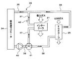
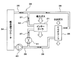
- FIG. 2 is a diagram showing a schematic configuration of the low water temperature cooling system of Example 1
- FIG. 3 is a diagram for explaining the relationship between the outside air environment and the appropriate flow rate.
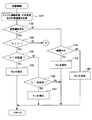
- FIG. 4 is a flowchart (part 1) showing a flow of processing of the flow rate control routine of the first embodiment.
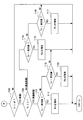
- FIG. 5 is a flowchart (part 2) showing the flow of the flow rate control routine of the first embodiment.
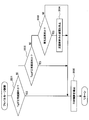
- FIG. 6 is a flowchart showing a flow of processing of the fail-safe control routine.
- FIG. 7 is a flowchart showing the flow of the flow rate control routine of the second embodiment.
- FIG. 8 is a diagram conceptually showing an example of a map of the flow rate ratio of the EGR cooler
- FIG. 9 is a diagram illustrating an example of a schematic configuration of a low water temperature cooling system of Example 3
- FIG. 10 is a diagram illustrating another example of a schematic configuration of the low water temperature cooling system according to the third embodiment.
- Example 1 of the present disclosure will be described with reference to FIGS.
- An air cleaner 13 is provided at the most upstream portion of the intake pipe 12 (intake passage) of the engine 11 that is an internal combustion engine.
- An air flow meter 14 for detecting the intake air amount is provided on the downstream side of the air cleaner 13.
- the exhaust pipe 15 of the engine 11 is provided with a catalyst 16 such as a three-way catalyst that purifies CO, HC, NO X and the like in the exhaust gas.
- the engine 11 is equipped with an exhaust turbine driven supercharger 17 for supercharging intake gas.
- the intake gas may be only intake air (fresh air) or may be a mixed gas of intake air and EGR gas.
- an exhaust turbine 18 is disposed on the upstream side of the catalyst 16 in the exhaust pipe 15, and a compressor 19 is disposed on the downstream side of the air flow meter 14 in the intake pipe 12.
- the supercharger 17 is connected so that the exhaust turbine 18 and the compressor 19 rotate integrally, and the exhaust turbine 18 is rotationally driven by the kinetic energy of the exhaust gas, so that the compressor 19 is rotationally driven to suck the intake gas.
- Supercharge is connected so that the exhaust turbine 18 and the compressor 19 rotate integrally, and the exhaust turbine 18 is rotationally driven by the kinetic energy of the exhaust gas, so that the compressor 19 is rotationally driven to suck the intake gas.
- a throttle valve 20 whose opening degree is adjusted by a motor (not shown) is provided on the downstream side of the compressor 19 in the intake pipe 12.
- a water-cooled intercooler 21 that cools the intake gas is provided integrally with a surge tank (not shown) on the downstream side of the throttle valve 20.
- the intercooler 21 cools the suction gas heated by the supercharger 17 and heated with cooling water. Thereby, the in-cylinder filling efficiency of intake gas can be increased and the output of the engine 11 can be increased.
- a fuel injection valve (not shown) for performing in-cylinder injection or intake port injection is attached to each cylinder of the engine 11.
- a spark plug (not shown) is attached to the cylinder head of the engine 11 for each cylinder, and the air-fuel mixture in each cylinder is ignited by spark discharge of each spark plug.
- the engine 11 is equipped with an LPL type (low pressure loop type) EGR device 22 that recirculates a part of the exhaust gas from the exhaust pipe 15 to the intake pipe 12 as EGR gas.
- an EGR pipe 23 is connected between a downstream side of the exhaust turbine 18 in the exhaust pipe 15 (for example, a downstream side of the catalyst 16) and an upstream side of the compressor 19 in the intake pipe 12.
- the EGR pipe 23 is provided with an EGR valve 24 that adjusts the EGR gas flow rate.
- the EGR pipe 23 has a water-cooled EGR cooler 25 that cools the EGR gas, a separator 26 that separates and collects condensed water in the EGR gas that has passed through the EGR cooler 25, and passes through the separator 26.
- an EGR heater 27 for warming the EGR gas.
- the EGR cooler 25 cools the EGR gas with low-temperature cooling water that is cooling water for the intercooler 21 to forcibly generate condensed water.
- the separator 26 separates and collects the condensed water in the EGR gas.
- the condensed water collected by the separator 26 is discharged to the exhaust pipe 15 through the pipe 28.
- the EGR heater 27 warms the EGR gas with high-temperature cooling water that is cooling water for the engine 11 and reduces the relative humidity of the EGR gas.
- an outside air temperature sensor 29 for detecting the outside air temperature (To) and an outside air humidity sensor 30 for detecting the outside air humidity are located in an area that is hardly affected by the heat of the engine 11 such as an upstream portion of the intake pipe 12 or the outside of the intake pipe 12. Is provided. Furthermore, an intake gas temperature sensor 31 that detects the temperature of the intake gas that has passed through the intercooler 21 is provided on the downstream side of the intercooler 21 (for example, a surge tank or an intake manifold). On the downstream side of the EGR cooler 25 (for example, between the EGR cooler 25 and the separator 26 or between the separator 26 and the EGR heater 27), an EGR gas temperature sensor 32 that detects the temperature of the EGR gas that has passed through the EGR cooler 25 is provided. Is provided.
- the outputs of these various sensors are input to an electronic control unit (ECU) 33.
- the ECU 33 is mainly composed of a microcomputer, and executes various engine control programs stored in a built-in ROM (storage medium), thereby depending on the engine operating state, the fuel injection amount, the ignition timing.
- the throttle opening (intake air amount) and the like are controlled.
- the ECU 33 calculates the target EGR rate according to the engine operating state (for example, the engine speed and the engine load), and controls the opening degree of the EGR valve 24 so as to realize the target EGR rate.
- the engine operating state for example, the engine speed and the engine load
- a path 37 and an EGR cooler flow path 38 for circulating cooling water via the EGR cooler 25 are connected in parallel.
- a low water temperature cooling water circuit 39 for circulating the cooling water cooled by the low water temperature radiator 34 to the intercooler 21 and the EGR cooler 25 is formed.
- an electric water pump 40 is provided in the outlet flow path 36, and a flow control valve 41 is provided in a branch portion between the intercooler flow path 37 and the EGR cooler flow path 38.
- the flow control valve 41 is configured to use a motor or the like as a drive source and adjust the flow rate ratio of the cooling water flowing through the intercooler 21 and the cooling water flowing through the EGR cooler 25 according to the operating position of the valve body.
- the flow rate control valve 41 is biased toward the initial position (position where the flow rate ratio of the cooling water flowing through the intercooler 21 is maximized), and when the energization is stopped, the valve body returns to the initial position and the intercooler.
- the self-returning function for returning to a state where the flow rate ratio of the cooling water flowing to 21 becomes maximum for example, 100%
- the intercooler flow path 37 is provided with a cooling water temperature sensor 42 that detects the temperature of the cooling water that has passed through the intercooler 21.
- the ECU 33 controls the flow rate of the cooling water flowing through the intercooler 21 by controlling the flow rate control valve 41 and the water pump 40 so as to reduce the deviation between the cooling water temperature detected by the cooling water temperature sensor 42 and the target water temperature.
- condensed water may be generated when the intake gas mixed with the EGR gas and the intake air (fresh air) is cooled by the intercooler 21.
- the condensed water may cause corrosion of metal parts.
- the EGR gas is dehumidified by cooling the EGR gas with the EGR cooler 25 to forcibly generate condensed water, and separating and collecting the condensed water in the EGR gas with the separator 26. Thereafter, the EGR gas is recirculated to the intake pipe 12 while the EGR gas is heated by the EGR heater 27 and the relative humidity is lowered.
- the appropriate flow rate of the cooling water flowing through the intercooler 21 (the flow rate that causes the intercooler 21 to function properly) or the EGR cooler 25
- the appropriate flow rate of the flowing cooling water (the flow rate that causes the EGR cooler 25 to function properly) changes.
- the flow rate ratio of the cooling water flowing through the intercooler 21 and the cooling water flowing through the EGR cooler 25 may be simply expressed as the flow rate ratio (Rc) of the intercooler 21 and the EGR cooler 25.
- the flow rate ratio of the cooling water flowing through the intercooler 21 is simply expressed as the flow rate ratio (Ric) of the intercooler 21
- the flow rate ratio of the cooling water flowing through the EGR cooler 25 is expressed as the flow rate ratio (Rec) of the EGR cooler 25.
- the flow rate of the cooling water flowing through the intercooler 21 may be simply expressed as the flow rate of the intercooler 21
- the flow rate of the cooling water flowing through the EGR cooler 25 may be simplified and expressed as the flow rate of the EGR cooler 25.
- the EGR cooler 25 If the flow rate of the EGR cooler 25 is low when the outside air temperature is low, the EGR cooler 25 cannot sufficiently cool the EGR gas, and the EGR gas may not be sufficiently dehumidified. Moreover, since the temperature of the cooling water is low when the outside air temperature is low, if the flow rate of the intercooler 21 is large, the intercooler 21 cools the intake gas to a temperature equal to or lower than the dew point temperature (the temperature at which condensed water is generated). Condensate may occur due to overcooling.
- the temperature of the cooling water also increases. Therefore, if the flow rate of the intercooler 21 is small, the intake gas cannot be sufficiently cooled by the intercooler 21, and the in-cylinder filling efficiency of the intake gas decreases. As a result, the output of the engine 11 may be reduced. Further, when the outside air temperature is high and the outside air humidity is high and the humidity is high, the dew point temperature of the intake gas becomes high. Therefore, if the flow rate of the intercooler 21 is excessive, the intercooler 21 cools the intake gas to the dew point temperature or less. Condensate may be generated due to overcooling.
- the flow rate control routine of FIGS. 4 and 5 is executed by the ECU 33 to control the flow rate control valve 41 according to the outside air environment (for example, the outside air temperature and the outside air humidity) and the engine operating state.
- the flow rate ratio between the intercooler 21 and the EGR cooler 25 is changed.
- the ECU 33 and the flow control valve 41 correspond to a low water temperature cooling device for an internal combustion engine.
- the flow rate control valve 41 By controlling the flow rate control valve 41 according to the outside air environment and the engine operating state to change the flow rate ratio between the intercooler 21 and the EGR cooler 25, the flow rate of the intercooler 21 and the EGR cooler according to the outside air environment and the engine operating state.
- the flow rate of 25 can be changed.
- the ECU 33 increases the flow rate ratio of the EGR cooler 25 as the outside air temperature is low (that is, when the outside air temperature is in a predetermined low temperature region (for example, a region where the outside air temperature is equal to or less than the first threshold value a1))
- the flow rate control valve 41 is controlled so as to reduce the flow rate ratio of the cooler 21. Accordingly, at a low temperature, the flow rate of the EGR cooler 25 is increased, the EGR gas is sufficiently cooled by the EGR cooler 25 to generate condensed water, and the EGR gas is sufficiently dehumidified.
- the temperature of the cooling water is lowered, but the flow rate of the intercooler 21 is decreased to prevent overcooling that causes the intercooler 21 to cool the intake gas to the dew point temperature or lower, thereby reducing the dew point of the intake gas. Cool to a predetermined temperature range higher than the temperature.
- the ECU 33 operates at a high temperature and low humidity in which the outside air temperature is a predetermined high temperature region (for example, a region where the outside air temperature is equal to or higher than the second threshold value a2) and the outside air humidity is a predetermined low humidity region (for example, a region where the outside air humidity is equal to or less than the third threshold value b).
- the flow rate control valve 41 is controlled so that the flow rate ratio of the intercooler 21 is increased as the outside air temperature is higher.
- the temperature of the cooling water increases at high temperatures and low humidity, but the flow rate of the intercooler 21 is increased and the intercooler 21 cools the intake gas to a predetermined temperature range higher than the dew point temperature.
- the ECU 33 sets the flow rate of the intercooler 21 at a high temperature and high humidity when the outside air temperature is in a high temperature region and the outside air humidity is in a predetermined high humidity region (for example, a region where the outside air humidity is higher than the third threshold value b).
- the flow control valve 41 is controlled so as to reduce the ratio.
- the dew point temperature of the intake gas becomes high at high temperature and high humidity, but the subcooling causes the intercooler 21 to reduce the flow rate of the intercooler 21 and cool the intake gas to the dew point temperature or less than at high temperature and low humidity.
- the intake gas is cooled to a predetermined temperature range higher than the dew point temperature.
- the ECU 33 performs feedforward control of the flow rate ratio of the intercooler 21 according to the engine operating state.
- the flow control valve 41 is feedforward controlled so as to decrease the flow rate ratio of the intercooler 21 when the engine 11 is decelerated.
- the process proceeds to 102, where it is determined whether or not the engine 11 is in a steady operation, for example, based on whether or not the absolute value of the change amount per predetermined time of the engine load or the engine speed is equal to or less than a predetermined value. To do.
- the process proceeds to 103 to determine whether or not the outside air temperature is a low temperature region equal to or lower than the first threshold value a1.
- the first threshold value a1 may be a fixed value set in advance, but may be changed according to the engine operating state (for example, engine load, engine speed, etc.).
- the routine proceeds to 104, where the outside air temperature is higher than the previous value (previous outside air temperature). Determine whether it is low.
- the flow proceeds to 105, and the flow rate control valve 41 is controlled so as to increase the flow rate ratio of the EGR cooler 25 by a predetermined value.
- the flow rate control valve 41 is controlled so that the flow rate ratio of the EGR cooler 25 is increased (that is, the flow rate ratio of the intercooler 21 is decreased) as the outside air temperature is lower.
- the process proceeds to 106 and it is determined whether or not the outside air temperature is higher than the previous value. If it is determined at 106 that the outside air temperature is higher than the previous value, the process proceeds to 107 and the flow rate control valve 41 is controlled to increase the flow rate ratio of the intercooler 21 by a predetermined value.
- the process proceeds to 108 in FIG. 5 to determine whether or not the outside air temperature is a high temperature region equal to or higher than the second threshold a2.
- the second threshold value a2 is higher than the first threshold value a1 and may be a fixed value set in advance. However, the second threshold value a2 may be changed according to the engine operating state (for example, engine load, engine speed, etc.). May be.
- the third threshold value b may be a fixed value set in advance, but may be changed according to the engine operating state (for example, engine load, engine speed, etc.).
- the process proceeds to 111, and the flow rate control valve 41 is controlled to increase the flow rate ratio of the intercooler 21 by a predetermined value.
- the flow rate control valve 41 is controlled so that the flow rate ratio of the intercooler 21 is increased (that is, the flow rate ratio of the EGR cooler 25 is decreased) as the outside air temperature is higher at high temperature and low humidity.
- the process proceeds to 112 and it is determined whether or not the outside air temperature is lower than the previous value. If it is determined at 112 that the outside air temperature is lower than the previous value, the process proceeds to 113, and the flow rate control valve 41 is controlled to increase the flow rate ratio of the EGR cooler 25 by a predetermined value.
- the process proceeds to 115, and the flow rate control valve 41 is controlled to increase the flow rate ratio of the EGR cooler 25 by a predetermined value.
- the flow rate control valve 41 is controlled so that the flow rate ratio of the EGR cooler 25 is increased as the outside air temperature is higher (that is, the flow rate ratio of the intercooler 21 is decreased) at the time of high temperature and high humidity.
- the flow rate control valve 41 is controlled so as to reduce the flow rate ratio of the intercooler 21.
- the process proceeds to 116 and it is determined whether or not the outside air temperature is lower than the previous value. If it is determined at 116 that the outside air temperature is lower than the previous value, the process proceeds to 117, and the flow rate control valve 41 is controlled to increase the flow rate ratio of the intercooler 21 by a predetermined value.
- the process proceeds to 118 to determine whether or not the engine 11 is decelerating, for example, per predetermined time of engine load or engine speed. Judgment is made based on whether the amount of decrease is equal to or greater than a predetermined value.
- the flow proceeds to 119, and the flow rate control valve 41 is controlled to increase the flow rate ratio of the EGR cooler 25 by a predetermined value.
- the flow rate control valve 41 is feedforward controlled so as to decrease the flow rate ratio of the intercooler 21.
- the flow proceeds to 120, and the flow rate control valve 41 is controlled to increase the flow rate ratio of the intercooler 21 by a predetermined value.
- the fail-safe control routine shown in FIG. 6 is repeatedly executed at a predetermined cycle during the power-on period of the ECU 33, and serves as a fail-safe control unit.
- this routine is started, first, at 201, the gas temperature after passage of the intercooler (Tig) detected by the intake gas temperature sensor 31 (that is, the temperature of the intake gas that has passed through the intercooler 21) is outside a predetermined normal range. It is determined whether or not there is.
- the process proceeds to 205, EGR control is prohibited, and the EGR valve 24 Is kept closed, and the recirculation of EGR gas is prohibited.
- the low water temperature cooling water circuit 39 includes an intercooler 21, an EGR cooler 25, a low water temperature radiator 34, flow paths 35 to 38, a water pump 40, a flow rate control valve 41, and the like.
- the routine proceeds to 202 and the gas temperature after passing through the EGR cooler (Teg) detected by the EGR gas temperature sensor 32 (that is, EGR). It is determined whether or not the temperature of the EGR gas that has passed through the cooler 25 is outside a predetermined normal range.
- the process proceeds to 203 and it is determined whether or not the electric system of the flow control valve 41 is abnormal.
- the process proceeds to 204, and energization of the flow control valve 41 is stopped. Thereby, the valve body of the flow control valve 41 returns to the initial position, and the flow rate ratio of the intercooler 21 becomes maximum (for example, 100%).
- routine proceeds to 205, where EGR control is prohibited, the EGR valve 24 is maintained in the closed state, and the recirculation of EGR gas is prohibited.
- the flow rate is set so that the flow rate ratio of the EGR cooler 25 is increased (that is, the flow rate ratio of the intercooler 21 is decreased) as the outside air temperature is low when the outside air temperature is a predetermined low temperature range.
- the control valve 41 is controlled. In this way, at a low temperature, the flow rate of the EGR cooler 25 can be increased, the EGR gas can be sufficiently cooled by the EGR cooler 25 to generate condensed water, and the EGR gas can be sufficiently dehumidified. .
- the temperature of the cooling water is lowered, but the flow rate of the intercooler 21 is decreased to prevent overcooling that causes the intercooler 21 to cool the intake gas to the dew point temperature or lower, thereby reducing the dew point of the intake gas. It can cool to the predetermined temperature range higher than temperature. Thereby, at the time of low temperature, generation
- the flow rate control valve 41 is set so that the flow rate ratio of the intercooler 21 is increased as the outside air temperature is high when the outside air temperature is a predetermined high temperature region and the outside air humidity is a predetermined low humidity region. Control. By doing so, the temperature of the cooling water becomes high at high temperature and low humidity, but the flow rate of the intercooler 21 can be increased, and the intercooler 21 can cool the intake gas to a predetermined temperature range higher than the dew point temperature. In addition, at the time of high temperature and low humidity, while suppressing the generation of condensed water in the intercooler 21, the intake gas can be appropriately cooled to prevent the in-cylinder charging efficiency from decreasing (the output from the engine 11 from decreasing).
- the flow rate control valve is configured so that the flow rate ratio of the intercooler 21 is smaller at high temperatures and high humidity when the outside air temperature is a predetermined high temperature region and the outdoor air humidity is a predetermined high humidity region than at high temperature and low humidity. 41 is controlled. In this way, the dew point temperature of the intake gas becomes higher at high temperature and high humidity, but the flow rate of the intercooler 21 is reduced compared to that at high temperature and low humidity, and the intake gas is cooled to below the dew point temperature by the intercooler 21. Therefore, the intake gas can be cooled to a predetermined temperature range higher than the dew point temperature.
- the flow rate control valve 41 when the engine 11 is decelerated, the flow rate control valve 41 is feedforward controlled so as to reduce the flow rate ratio of the intercooler 21. In this way, when the flow rate of the intake gas decreases during the deceleration of the engine 11, the flow rate of the cooling water flowing through the intercooler 21 can be quickly reduced, and the intake gas is supercooled in the intercooler 21. Can be prevented.
- the intercooler flow path 37 and the EGR cooler flow path 38 are connected in parallel, and a flow control valve 41 is provided at a branch portion between the intercooler flow path 37 and the EGR cooler flow path 38.
- the flow rate control valve 41 can reliably change the flow rate ratio between the intercooler 21 and the EGR cooler 25.
- the temperature of the cooling water flowing downstream is higher than the temperature of the cooling water flowing upstream of the intercooler and the EGR cooler. It will be high.
- the intercooler flow path 37 and the EGR cooler flow path 38 are connected in parallel, cooling water having substantially the same temperature can be supplied to the intercooler 21 and the EGR cooler 25. it can.
- the low water temperature cooling water circuit 39 Is determined to be abnormal, and the recirculation of EGR gas is prohibited. In this way, when the low water temperature cooling water circuit 39 is abnormal, the recirculation of the EGR gas can be prohibited and the generation of condensed water in the intercooler 21 can be suppressed.
- the flow control valve 41 has a self-return function that returns to a state in which the flow rate ratio of the intercooler 21 is maximized when the energization is stopped.
- energization of the flow control valve 41 is stopped and the recirculation of the EGR gas is prohibited. In this way, when the electrical system of the flow control valve 41 is abnormal, the recirculation of the EGR gas is prohibited, and the flow rate of the intercooler 21 is maximized while suppressing the generation of condensed water in the intercooler 21. The cooling performance of the intake gas can be ensured.
- the separator 26 that separates and collects the condensed water in the EGR gas that has passed through the EGR cooler 25 and the EGR heater 27 that warms the EGR gas that has passed through the separator 26 are provided.
- production suppression effect of the condensed water in the cooler 21 can be heightened.
- Example 2 of the present disclosure will be described with reference to FIGS. 7 and 8. However, description of substantially the same parts as those in the first embodiment will be omitted or simplified, and different parts from the first embodiment will be mainly described.
- the ECU 33 executes the flow rate control routine of FIG. 7 to control the flow rate control valve 41 in accordance with the outside air environment and the engine operating state to change the flow rate ratio between the intercooler 21 and the EGR cooler 25.
- the flow proceeds to 303 and the flow rate ratio of the EGR cooler 25 corresponding to the outside air temperature and the outside air humidity is referred to with reference to the flow rate map of the EGR cooler 25 shown in FIG. Is calculated.
- the map of the flow rate ratio of the EGR cooler 25 is created in advance based on test data, design data, etc., and is stored in the ROM of the ECU 33.
- the map of the flow rate ratio of the EGR cooler 25 indicates that, for example, in a low temperature region where the outside air temperature is equal to or lower than the fourth threshold value a, the flow rate ratio of the EGR cooler 25 increases (that is, the flow rate ratio of the intercooler 21 decreases). ) Is set as follows. In a high temperature region where the outside air temperature is higher than the fourth threshold value a and a low humidity region where the outside air humidity is equal to or less than the third threshold value b, the flow rate ratio of the EGR cooler 25 decreases as the outside air temperature increases and the outside air humidity decreases (that is, The flow rate ratio of the intercooler 21 is set to increase).
- the flow rate ratio of the EGR cooler 25 increases as the outside air temperature increases and the outside air humidity increases. (That is, the flow rate ratio of the intercooler 21 is reduced), and the flow rate ratio of the intercooler 21 is made smaller than that at high temperature and low humidity.
- the map of the flow rate ratio of the EGR cooler 25 may be changed according to the engine operating state (for example, engine load, engine speed, etc.).
- the process proceeds to 305 to determine whether the engine 11 is decelerating. If it is determined in 305 that the vehicle is decelerating, the flow proceeds to 306, and the flow rate control valve 41 is controlled to increase the flow rate ratio of the EGR cooler 25 by a predetermined value. Thus, when the engine 11 is decelerated, the flow rate control valve 41 is feedforward controlled so as to decrease the flow rate ratio of the intercooler 21.
- the flow proceeds to 307, and the flow rate control valve 41 is controlled so as to increase the flow rate ratio of the intercooler 21 by a predetermined value.
- Example 3 of the present disclosure will be described with reference to FIGS. 9 and 10.
- substantially the same parts as those in the first embodiment are denoted by the same reference numerals, and the description thereof is omitted or simplified, and the parts different from the first embodiment will be mainly described.
- a flow rate control valve 41 is provided in the intercooler flow path 37, and the flow rate of the intercooler 21 is adjusted by the flow rate control valve 41, whereby the intercooler 21 and the EGR cooler 25. Adjust the flow rate ratio.
- a flow rate control valve 41 is provided in the EGR cooler flow path 38, and the flow rate of the EGR cooler 25 is adjusted by the flow rate control valve 41, whereby the flow rate ratio of the intercooler 21 and the EGR cooler 25. You may make it adjust. In either case, the flow rate control valve 41 can reliably change the flow rate ratio between the intercooler 21 and the EGR cooler 25. In addition, you may provide the flow control valve 41 in both the intercooler flow path 37 and the EGR cooler flow path 38, respectively.
- some or all of the functions executed by the ECU 33 may be implemented by one or a plurality of ICs. You may comprise.
Landscapes
- Engineering & Computer Science (AREA)
- Chemical & Material Sciences (AREA)
- Combustion & Propulsion (AREA)
- Mechanical Engineering (AREA)
- General Engineering & Computer Science (AREA)
- Physics & Mathematics (AREA)
- Thermal Sciences (AREA)
- Chemical Kinetics & Catalysis (AREA)
- Exhaust-Gas Circulating Devices (AREA)
- Supercharger (AREA)
Abstract
内燃機関(11)の排出ガスの一部をEGRガスとして吸気通路(12)へ還流させるEGR装置(22)と、内燃機関の吸入ガスを冷却するインタークーラ(21)とEGRガスを冷却するEGRクーラ(25)とに冷却水を循環させる低水温冷却水回路(39)とを備えた内燃機関の低水温冷却装置において、インタークーラに流れる冷却水とEGRクーラに流れる冷却水の流量比率を調節する流量制御弁(41)と、外気環境と内燃機関の運転状態とに応じて流量制御弁を制御してインタークーラに流れる冷却水とEGRクーラに流れる冷却水の流量比率を変化させる制御ユニット(33、101~120、201~205)とを備えている内燃機関の低水温冷却装置。
Description
本出願は、2015年5月7日に出願された日本特許出願番号2015-94785号に基づくもので、ここにその記載内容を援用する。
本開示は、インタークーラとEGRクーラに冷却水を循環させる低水温冷却水回路を備えた内燃機関の低水温冷却装置に関するものである。
車両に搭載される内燃機関においては、燃費向上、ノッキングや排気エミッションの低減等を目的として、排出ガスの一部をEGRガスとして吸気通路へ還流させるEGR装置を搭載する。しかし、吸気通路へ還流されるEGRガス中の水分が多いと、EGRガスと吸入空気(新気)が混合した吸入ガスがインタークーラで冷却されたときに凝縮水が発生することがあり、この凝縮水により金属部品の腐食等が発生する可能性がある。
そこで、インタークーラでの凝縮水の発生を抑制する技術として、例えば、特許文献1に記載されたものがある。このものは、インタークーラとEGRクーラに冷却水を循環させる冷却水回路を設け、EGRクーラでEGRガスを冷却して強制的に凝縮水を発生させて、その凝縮水をトラップ部で捕集して除湿した後、EGRヒータでEGRガスを暖めて相対湿度を低下させた状態でEGRガスを吸気通路へ還流させる。
発明者は、インタークーラとEGRクーラに冷却水を循環させる低水温冷却水回路を備えたシステムを研究しているが、その研究過程で次のような新たな課題が判明した。
外気温度が低い低温時に、EGRクーラに流れる冷却水の流量が少ないと、EGRクーラでEGRガスを十分に冷却できず、EGRガスを十分に除湿できない可能性がある。しかも、外気温度が低い低温時には、冷却水の温度も低くなるため、インタークーラに流れる冷却水の流量が多いと、インタークーラで吸入ガスを露点温度(凝縮水が発生する温度)以下まで冷却してしまう過冷却になって凝縮水が発生する可能性がある。
一方、外気温度が高い高温時には、冷却水の温度も高くなるため、インタークーラに流れる冷却水の流量が少ないと、インタークーラで吸入ガスを十分に冷却できず、吸入ガスの筒内充填効率が低下して内燃機関の出力低下を招く可能性がある。また、外気温度が高くても外気湿度が高い高温高湿時には、吸入ガスの露点温度が高くなるため、インタークーラに流れる冷却水の流量が多過ぎると、インタークーラで吸入ガスを露点温度以下まで冷却してしまう過冷却になって凝縮水が発生する可能性がある。
本開示の目的は、外気環境に左右されずに吸入ガスの冷却と凝縮水の発生抑制を両立することができる内燃機関の低水温冷却装置を提供することにある。
本開示の一態様による内燃機関の低水温冷却装置は、内燃機関の排出ガスの一部をEGRガスとして吸気通路へ還流させるEGR装置と、内燃機関の吸入ガスを冷却するインタークーラとEGRガスを冷却するEGRクーラとに冷却水を循環させる低水温冷却水回路とを備えた内燃機関の低水温冷却装置であって、インタークーラに流れる冷却水とEGRクーラに流れる冷却水の流量比率を調節する流量制御弁と、外気環境と内燃機関の運転状態とに応じて流量制御弁を制御してインタークーラに流れる冷却水とEGRクーラに流れる冷却水の流量比率を変化させる制御ユニットとを備える。
この構成では、外気環境と内燃機関の運転状態とに応じて流量制御弁を制御してインタークーラに流れる冷却水とEGRクーラに流れる冷却水の流量比率を変化させることで、外気環境や内燃機関の運転状態に応じてインタークーラに流れる冷却水の流量やEGRクーラに流れる冷却水の流量を変化させることができる。これにより、インタークーラに流れる冷却水の流量やEGRクーラに流れる冷却水の流量を、そのときの外気環境に対応した適正な流量に制御することが可能となり、外気環境に左右されずに吸入ガスの冷却と凝縮水の発生抑制を両立することができる。
本開示についての上記目的およびその他の目的、特徴や利点は、添付の図面を参照しながら下記の詳細な記述により、より明確になる。その図面は、
図1は本開示の実施例1におけるエンジン制御システムの概略構成を示す図であり、
図2は実施例1の低水温冷却システムの概略構成を示す図であり、
図3は外気環境と適正流量との関係を説明する図であり、
図4は実施例1の流量制御ルーチンの処理の流れを示すフローチャート(その1)であり、
図5は実施例1の流量制御ルーチンの処理の流れを示すフローチャート(その2)であり、
図6はフェイルセーフ制御ルーチンの処理の流れを示すフローチャートであり、
図7は実施例2の流量制御ルーチンの処理の流れを示すフローチャートであり、
図8はEGRクーラの流量比率のマップの一例を概念的に示す図であり、
図9は実施例3の低水温冷却システムの概略構成の一例を示す図であり、
図10は実施例3の低水温冷却システムの概略構成のもう一つの例を示す図である。
以下、本開示を実施するための形態を具体化した幾つかの実施例を説明する。
本開示の実施例1を図1乃至図6に基づいて説明する。
まず、図1に基づいてエンジン制御システムの概略構成を説明する。
内燃機関であるエンジン11の吸気管12(吸気通路)の最上流部には、エアクリーナ13が設けられている。このエアクリーナ13の下流側に、吸入空気量を検出するエアフローメータ14が設けられている。一方、エンジン11の排気管15には、排出ガス中のCO、HC、NOX等を浄化する三元触媒等の触媒16が設置されている。
このエンジン11には、吸入ガスを過給する排気タービン駆動式の過給機17が搭載されている。ここで、吸入ガスは、吸入空気(新気)のみの場合もあるが、吸入空気とEGRガスとの混合ガスの場合もある。過給機17は、排気管15のうちの触媒16の上流側に排気タービン18が配置され、吸気管12のうちのエアフローメータ14の下流側にコンプレッサ19が配置されている。この過給機17は、排気タービン18とコンプレッサ19とが一体的に回転するように連結され、排出ガスの運動エネルギで排気タービン18を回転駆動することでコンプレッサ19を回転駆動して吸入ガスを過給する。
吸気管12のうちのコンプレッサ19の下流側には、モータ(図示せず)によって開度調節されるスロットルバルブ20が設けられている。このスロットルバルブ20の下流側に、吸入ガスを冷却する水冷式のインタークーラ21がサージタンク(図示せず)と一体的に設けられている。このインタークーラ21は、過給機17で過給されて昇温した吸入ガスを冷却水で冷却する。これにより、吸入ガスの筒内充填効率を高めて、エンジン11の出力を高めることができる。
また、エンジン11の各気筒毎に筒内噴射又は吸気ポート噴射を行う燃料噴射弁(図示せず)が取り付けられている。更にエンジン11のシリンダヘッドには、各気筒毎に点火プラグ(図示せず)が取り付けられ、各点火プラグの火花放電によって各気筒内の混合気に着火される。
このエンジン11には、排気管15から排出ガスの一部をEGRガスとして吸気管12へ還流させるLPL方式(低圧ループ方式)のEGR装置22が搭載されている。このEGR装置22は、排気管15のうちの排気タービン18の下流側(例えば触媒16の下流側)と吸気管12のうちのコンプレッサ19の上流側との間にEGR配管23が接続されている。このEGR配管23に、EGRガス流量を調節するEGR弁24が設けられている。更に、EGR配管23には、EGRガスを冷却する水冷式のEGRクーラ25と、このEGRクーラ25を通過したEGRガス中の凝縮水を分離して捕集するセパレータ26と、このセパレータ26を通過したEGRガスを暖めるEGRヒータ27とが設けられている。
EGRクーラ25は、インタークーラ21の冷却水である低水温系の冷却水でEGRガスを冷却して強制的に凝縮水を発生させる。セパレータ26は、EGRガス中の凝縮水を分離して捕集する。セパレータ26で捕集された凝縮水は、配管28を通して排気管15へ排出される。EGRヒータ27は、エンジン11の冷却水である高水温系の冷却水でEGRガスを暖めてEGRガスの相対湿度を低下させる。
また、吸気管12の上流部又は吸気管12の外部等のエンジン11の熱の影響を受け難い場所に、外気温度(To)を検出する外気温度センサ29と外気湿度を検出する外気湿度センサ30が設けられている。更に、インタークーラ21の下流側(例えばサージタンク又は吸気マニホールド)には、インタークーラ21を通過した吸入ガスの温度を検出する吸入ガス温度センサ31が設けられている。EGRクーラ25の下流側(例えばEGRクーラ25とセパレータ26との間又はセパレータ26とEGRヒータ27との間)には、EGRクーラ25を通過したEGRガスの温度を検出するEGRガス温度センサ32が設けられている。
これら各種センサの出力は、電子制御装置(ECU)33に入力される。このECU33は、マイクロコンピュータを主体として構成され、内蔵されたROM(記憶媒体)に記憶された各種のエンジン制御用のプログラムを実行することで、エンジン運転状態に応じて、燃料噴射量、点火時期、スロットル開度(吸入空気量)等を制御する。
その際、ECU33は、エンジン運転状態(例えばエンジン回転速度とエンジン負荷等)に応じて目標EGR率を算出し、この目標EGR率を実現するようにEGR弁24の開度を制御する。
次に、図2に基づいて低水温冷却システムの概略構成を説明する。
低水温ラジエータ34の入口に接続された入口流路35と、低水温ラジエータ34の出口に接続された出口流路36との間には、インタークーラ21を介して冷却水を循環させるインタークーラ流路37と、EGRクーラ25を介して冷却水を循環させるEGRクーラ流路38とが並列に接続されている。これにより、低水温ラジエータ34で冷却された冷却水をインタークーラ21とEGRクーラ25とに循環させる低水温冷却水回路39が形成されている。
この低水温冷却水回路39は、出口流路36に、電動式のウォータポンプ40が設けられ、インタークーラ流路37とEGRクーラ流路38との分岐部に、流量制御弁41が設けられている。この流量制御弁41は、モータ等を駆動源とし、弁体の動作位置に応じてインタークーラ21に流れる冷却水とEGRクーラ25に流れる冷却水の流量比率を調節するように構成されている。また、流量制御弁41は、弁体が初期位置(インタークーラ21に流れる冷却水の流量比率が最大になる位置)の方向に付勢され、通電停止時に弁体が初期位置に戻ってインタークーラ21に流れる冷却水の流量比率が最大(例えば100%)になる状態に戻る自戻り機能を備えている。
インタークーラ流路37には、インタークーラ21を通過した冷却水の温度を検出する冷却水温センサ42が設けられている。ECU33は、冷却水温センサ42で検出した冷却水温と目標水温との偏差を小さくするように流量制御弁41やウォータポンプ40を制御してインタークーラ21に流れる冷却水の流量をフィードバック制御する。
ところで、吸気管12へ還流されるEGRガス中の水分が多いと、EGRガスと吸入空気(新気)が混合した吸入ガスがインタークーラ21で冷却されたときに凝縮水が発生することがあり、この凝縮水により金属部品の腐食等が発生する可能性がある。
この対策として、EGRクーラ25でEGRガスを冷却して強制的に凝縮水を発生させ、セパレータ26でEGRガス中の凝縮水を分離して捕集することで、EGRガスの除湿を行う。この後、EGRヒータ27でEGRガスを暖めて相対湿度を低下させた状態でEGRガスを吸気管12へ還流させる。
しかし、図3に示すように、外気環境(例えば外気温度と外気湿度)に応じて、インタークーラ21に流れる冷却水の適正な流量(インタークーラ21を適正に機能させる流量)やEGRクーラ25に流れる冷却水の適正な流量(EGRクーラ25を適正に機能させる流量)が変化する。
以下の説明では、インタークーラ21に流れる冷却水とEGRクーラ25に流れる冷却水の流量比率をインタークーラ21とEGRクーラ25の流量比率(Rc)と簡略化して表記することもある。また、インタークーラ21に流れる冷却水の流量比率をインタークーラ21の流量比率(Ric)と簡略化して表記し、EGRクーラ25に流れる冷却水の流量比率をEGRクーラ25の流量比率(Rec)と簡略化して表記することもある。更に、インタークーラ21に流れる冷却水の流量をインタークーラ21の流量と簡略化して表記し、EGRクーラ25に流れる冷却水の流量をEGRクーラ25の流量と簡略化して表記することもある。
外気温度が低い低温時に、EGRクーラ25の流量が少ないと、EGRクーラ25でEGRガスを十分に冷却できず、EGRガスを十分に除湿できない可能性がある。しかも、外気温度が低い低温時には、冷却水の温度も低くなるため、インタークーラ21の流量が多いと、インタークーラ21で吸入ガスを露点温度(凝縮水が発生する温度)以下まで冷却してしまう過冷却になって凝縮水が発生する可能性がある。
一方、外気温度が高い高温時には、冷却水の温度も高くなるため、インタークーラ21の流量が少ないと、インタークーラ21で吸入ガスを十分に冷却できず、吸入ガスの筒内充填効率が低下してエンジン11の出力低下を招く可能性がある。また、外気温度が高くても外気湿度が高い高温高湿時には、吸入ガスの露点温度が高くなるため、インタークーラ21の流量が多過ぎると、インタークーラ21で吸入ガスを露点温度以下まで冷却してしまう過冷却になって凝縮水が発生する可能性がある。
そこで、本実施例1では、ECU33により図4及び図5の流量制御ルーチンを実行することで、外気環境(例えば外気温度と外気湿度)とエンジン運転状態とに応じて流量制御弁41を制御してインタークーラ21とEGRクーラ25の流量比率を変化させる。ECU33と流量制御弁41は、内燃機関の低水温冷却装置に相当する。
外気環境とエンジン運転状態に応じて流量制御弁41を制御してインタークーラ21とEGRクーラ25の流量比率を変化させることで、外気環境やエンジン運転状態に応じてインタークーラ21の流量やEGRクーラ25の流量を変化させることができる。これにより、インタークーラ21の流量やEGRクーラ25の流量を、そのときの外気環境に対応した適正な流量に制御することが可能となり、外気環境(例えば外気温度や外気湿度)に左右されずに吸入ガスの冷却と凝縮水の発生抑制を両立することができる。
具体的には、ECU33は、外気温度が所定の低温領域(例えば外気温度が第1閾値a1以下の領域)となる低温時には、外気温度が低いほどEGRクーラ25の流量比率を増加させる(つまりインタークーラ21の流量比率を減少させる)ように流量制御弁41を制御する。これにより、低温時に、EGRクーラ25の流量を増加させて、EGRクーラ25でEGRガスを十分に冷却して凝縮水を発生させて、EGRガスを十分に除湿する。更に、低温時には、冷却水の温度が低くなるが、インタークーラ21の流量を減少させて、インタークーラ21で吸入ガスを露点温度以下まで冷却してしまう過冷却を防止して、吸入ガスを露点温度よりも高い所定温度範囲まで冷却する。
また、ECU33は、外気温度が所定の高温領域(例えば外気温度が第2閾値a2以上の領域)で外気湿度が所定の低湿領域(例えば外気湿度が第3閾値b以下の領域)となる高温低湿時には、外気温度が高いほどインタークーラ21の流量比率を増加させるように流量制御弁41を制御する。これにより、高温低湿時には、冷却水の温度が高くなるが、インタークーラ21の流量を増加させて、インタークーラ21で吸入ガスを露点温度よりも高い所定温度範囲まで冷却する。
更に、ECU33は、外気温度が高温領域で外気湿度が所定の高湿領域(例えば外気湿度が第3閾値bよりも高い領域)となる高温高湿時には、高温低湿時よりもインタークーラ21の流量比率を小さくするように流量制御弁41を制御する。これにより、高温高湿時には、吸入ガスの露点温度が高くなるが、高温低湿時よりもインタークーラ21の流量を少なくして、インタークーラ21で吸入ガスを露点温度以下まで冷却してしまう過冷却を防止して、吸入ガスを露点温度よりも高い所定温度範囲まで冷却する。
また、冷却水温センサ42の出力に基づいてインタークーラ21の流量をフィードバック制御するシステムでは、エンジン11の減速時に吸入ガスの流量が低下したときに、吸入ガスの流量に対してインタークーラ21に流れる冷却水の流量が一時的に多い状態になって、インタークーラ21で吸入ガスを過冷却してしまう可能性がある。
そこで、ECU33は、エンジン運転状態に応じてインタークーラ21の流量比率をフィードフォワード制御する。具体的には、エンジン11の減速時にインタークーラ21の流量比率を減少させるように流量制御弁41をフィードフォワード制御する。これにより、エンジン11の減速時に吸入ガスの流量が低下したときに、インタークーラ21に流れる冷却水の流量を速やかに減少させる。
以下、本実施例1でECU33が実行する図4及び図5の流量制御ルーチンの処理内容を説明する。
図4及び図5に示す流量制御ルーチンは、ECU33の電源オン期間中に所定周期で繰り返し実行され、制御ユニットとしての役割を果たす。本ルーチンが起動されると、まず、101で、エンジン運転状態(例えばエンジン負荷やエンジン回転速度等)、外気温度センサ29で検出した外気温度、外気湿度センサ30で検出した外気湿度を取得する。
この後、102に進み、エンジン11が定常運転中であるか否かを、例えば、エンジン負荷やエンジン回転速度の所定時間当りの変化量の絶対値が所定値以下であるか否か等によって判定する。
102で、定常運転中と判定された場合には、103に進み、外気温度が第1閾値a1以下の低温領域であるか否かを判定する。ここで、第1閾値a1は、予め設定した固定値としても良いが、エンジン運転状態(例えばエンジン負荷やエンジン回転速度等)に応じて変化させるようにしても良い。
103で、外気温度が第1閾値a1以下の低温領域であると判定された場合には、低温時であると判断して、104に進み、外気温度が前回値(前回の外気温度)よりも低いか否かを判定する。
104で、外気温度が前回値よりも低いと判定された場合には、105に進み、EGRクーラ25の流量比率を所定値だけ増加させるように流量制御弁41を制御する。これにより、低温時に、外気温度が低いほどEGRクーラ25の流量比率を増加させる(つまりインタークーラ21の流量比率を減少させる)ように流量制御弁41を制御する。
これに対して、上記104で、外気温度が前回値以上と判定された場合には、106に進み、外気温度が前回値よりも高いか否かを判定する。106で、外気温度が前回値よりも高いと判定された場合には、107に進み、インタークーラ21の流量比率を所定値だけ増加させるように流量制御弁41を制御する。
一方、上記103で、外気温度が第1閾値a1よりも高いと判定された場合には、図5の108に進み、外気温度が第2閾値a2以上の高温領域であるか否かを判定する。ここで、第2閾値a2は、第1閾値a1よりも高い値であり、予め設定した固定値としても良いが、エンジン運転状態(例えばエンジン負荷やエンジン回転速度等)に応じて変化させるようにしても良い。
108で、外気温度が第2閾値a2以上の高温領域であると判定された場合には、高温時であると判断して、109に進み、外気湿度が第3閾値b以下の低湿領域であるか否かを判定する。ここで、第3閾値bは、予め設定した固定値としても良いが、エンジン運転状態(例えばエンジン負荷やエンジン回転速度等)に応じて変化させるようにしても良い。
109で、外気湿度が第3閾値b以下の低湿領域であると判定された場合には、高温低湿時であると判断して、110に進み、外気温度が前回値よりも高いか否かを判定する。
110で、外気温度が前回値よりも高いと判定された場合には、111に進み、インタークーラ21の流量比率を所定値だけ増加させるように流量制御弁41を制御する。これにより、高温低湿時に、外気温度が高いほどインタークーラ21の流量比率を増加させる(つまりEGRクーラ25の流量比率を減少させる)ように流量制御弁41を制御する。
これに対して、上記110で、外気温度が前回値以下と判定された場合には、112に進み、外気温度が前回値よりも低いか否かを判定する。112で、外気温度が前回値よりも低いと判定された場合には、113に進み、EGRクーラ25の流量比率を所定値だけ増加させるように流量制御弁41を制御する。
一方、上記109で、外気湿度が第3閾値bよりも高い高湿領域であると判定された場合には、高温高湿時であると判断して、114に進み、外気温度が前回値よりも高いか否かを判定する。
114で、外気温度が前回値よりも高いと判定された場合には、115に進み、EGRクーラ25の流量比率を所定値だけ増加させるように流量制御弁41を制御する。これにより、高温高湿時に、外気温度が高いほどEGRクーラ25の流量比率を増加させる(つまりインタークーラ21の流量比率を減少させる)ように流量制御弁41を制御して、高温低湿時よりもインタークーラ21の流量比率を小さくするように流量制御弁41を制御する。
これに対して、上記114で、外気温度が前回値以下と判定された場合には、116に進み、外気温度が前回値よりも低いか否かを判定する。116で、外気温度が前回値よりも低いと判定された場合には、117に進み、インタークーラ21の流量比率を所定値だけ増加させるように流量制御弁41を制御する。
一方、図4の102で、定常運転中ではないと判定された場合には、118に進み、エンジン11の減速中であるか否かを、例えば、エンジン負荷やエンジン回転速度の所定時間当りの減少量が所定値以上であるか否か等によって判定する。
118で、減速中と判定された場合には、119に進み、EGRクーラ25の流量比率を所定値だけ増加させるように流量制御弁41を制御する。これにより、エンジン11の減速時に、インタークーラ21の流量比率を減少させるように流量制御弁41をフィードフォワード制御する。
これに対して、上記118で、減速中ではないと判定された場合には、120に進み、インタークーラ21の流量比率を所定値だけ増加させるように流量制御弁41を制御する。
次に、本実施例1でECU33が実行する図6のフェイルセーフ制御ルーチンの処理内容を説明する。
図6に示すフェイルセーフ制御ルーチンは、ECU33の電源オン期間中に所定周期で繰り返し実行され、フェイルセーフ制御ユニットとしての役割を果たす。本ルーチンが起動されると、まず、201で、吸入ガス温度センサ31で検出したインタークーラ通過後ガス温度(Tig)(つまりインタークーラ21を通過した吸入ガスの温度)が所定の正常範囲外であるか否かを判定する。
201で、インタークーラ通過後ガス温度が正常範囲外であると判定された場合には、低水温冷却水回路39の異常と判定して、205に進み、EGR制御を禁止して、EGR弁24を閉弁状態に維持して、EGRガスの還流を禁止する。ここで、低水温冷却水回路39は、インタークーラ21、EGRクーラ25、低水温ラジエータ34、流路35~38、ウォータポンプ40、流量制御弁41等を含むものとする。
一方、上記201で、インタークーラ通過後ガス温度が正常範囲内であると判定された場合には、202に進み、EGRガス温度センサ32で検出したEGRクーラ通過後ガス温度(Teg)(つまりEGRクーラ25を通過したEGRガスの温度)が所定の正常範囲外であるか否かを判定する。
202で、EGRクーラ通過後ガス温度が正常範囲外であると判定された場合には、低水温冷却水回路39の異常と判定して、205に進み、EGR制御を禁止して、EGR弁24を閉弁状態に維持して、EGRガスの還流を禁止する。
一方、上記202で、EGRクーラ通過後ガス温度が正常範囲内であると判定された場合には、203に進み、流量制御弁41の電気系異常であるか否かを判定する。
203で、流量制御弁41の電気系異常と判定された場合には、204に進み、流量制御弁41への通電を停止する。これにより、流量制御弁41の弁体が初期位置に戻ってインタークーラ21の流量比率が最大(例えば100%)になる。
この後、205に進み、EGR制御を禁止して、EGR弁24を閉弁状態に維持して、EGRガスの還流を禁止する。
以上説明した本実施例1では、外気温度が所定の低温領域となる低温時に、外気温度が低いほどEGRクーラ25の流量比率を増加させる(つまりインタークーラ21の流量比率を減少させる)ように流量制御弁41を制御する。このようにすれば、低温時に、EGRクーラ25の流量を増加させて、EGRクーラ25でEGRガスを十分に冷却して凝縮水を発生させることができ、EGRガスを十分に除湿することができる。更に、低温時には、冷却水の温度が低くなるが、インタークーラ21の流量を減少させて、インタークーラ21で吸入ガスを露点温度以下まで冷却してしまう過冷却を防止して、吸入ガスを露点温度よりも高い所定温度範囲まで冷却することができる。これにより、低温時に、インタークーラ21での凝縮水の発生を抑制しながら、吸入ガスを適度に冷却して筒内充填効率の低下(エンジン11の出力低下)を防止することができる。
また、本実施例1では、外気温度が所定の高温領域で外気湿度が所定の低湿領域となる高温低湿時に、外気温度が高いほどインタークーラ21の流量比率を増加させるように流量制御弁41を制御する。このようにすれば、高温低湿時には、冷却水の温度が高くなるが、インタークーラ21の流量を増加させて、インタークーラ21で吸入ガスを露点温度よりも高い所定温度範囲まで冷却することができ、高温低湿時に、インタークーラ21での凝縮水の発生を抑制しながら、吸入ガスを適度に冷却して筒内充填効率の低下(エンジン11の出力低下)を防止することができる。
更に、本実施例1では、外気温度が所定の高温領域で外気湿度が所定の高湿領域となる高温高湿時に、高温低湿時よりもインタークーラ21の流量比率を小さくするように流量制御弁41を制御する。このようにすれば、高温高湿時には、吸入ガスの露点温度が高くなるが、高温低湿時よりもインタークーラ21の流量を少なくして、インタークーラ21で吸入ガスを露点温度以下まで冷却してしまう過冷却を防止して、吸入ガスを露点温度よりも高い所定温度範囲まで冷却することができる。これにより、高温高湿時に、インタークーラ21での凝縮水の発生を抑制しながら、吸入ガスを適度に冷却して筒内充填効率の低下(エンジン11の出力低下)を防止することができる。
また、本実施例1では、エンジン11の減速時に、インタークーラ21の流量比率を減少させるように流量制御弁41をフィードフォワード制御する。このようにすれば、エンジン11の減速時に、吸入ガスの流量が低下したときに、インタークーラ21に流れる冷却水の流量を速やかに減少させることができ、インタークーラ21での吸入ガスの過冷却を防止することができる。
また、本実施例1では、インタークーラ流路37とEGRクーラ流路38とを並列に接続し、インタークーラ流路37とEGRクーラ流路38との分岐部に流量制御弁41を設ける。これにより、流量制御弁41でインタークーラ21とEGRクーラ25の流量比率を確実に変化させることができる。
ところで、インタークーラ流路とEGRクーラ流路とを直列に接続した場合には、インタークーラとEGRクーラのうちの上流側を流れる冷却水の温度よりも下流側を流れる冷却水の温度の方が高くなってしまう。これに対して、本実施例1では、インタークーラ流路37とEGRクーラ流路38とを並列に接続しているため、インタークーラ21とEGRクーラ25にほぼ同じ温度の冷却水を流すことができる。
また、本実施例1では、インタークーラ通過後ガス温度が所定の正常範囲外になった場合や、EGRクーラ通過後ガス温度が所定の正常範囲外になった場合に、低水温冷却水回路39の異常と判定して、EGRガスの還流を禁止する。このようにすれば、低水温冷却水回路39の異常時に、EGRガスの還流を禁止して、インタークーラ21での凝縮水の発生を抑制することができる。
更に、本実施例1では、流量制御弁41は、通電停止時にインタークーラ21の流量比率が最大になる状態に戻る自戻り機能を備え、流量制御弁41の電気系異常と判定された場合に、流量制御弁41への通電を停止する共にEGRガスの還流を禁止する。このようにすれば、流量制御弁41の電気系異常時に、EGRガスの還流を禁止して、インタークーラ21での凝縮水の発生を抑制しつつ、インタークーラ21の流量比率を最大にして、吸入ガスの冷却性能を確保することができる。
また、本実施例1では、EGRクーラ25を通過したEGRガス中の凝縮水を分離して捕集するセパレータ26と、このセパレータ26を通過したEGRガスを暖めるEGRヒータ27とを備えたため、インタークーラ21での凝縮水の発生抑制効果を高めることができる。
次に、図7及び図8を用いて本開示の実施例2を説明する。但し、実施例1と実質的に同一部分については説明を省略又は簡略化し、主として実施例1と異なる部分について説明する。
本実施例2では、ECU33により図7の流量制御ルーチンを実行することで、外気環境とエンジン運転状態とに応じて流量制御弁41を制御してインタークーラ21とEGRクーラ25の流量比率を変化させる。
図7の流量制御ルーチンでは、まず、301で、エンジン運転状態、外気温度、外気湿度を取得した後、302に進み、エンジン11が定常運転中であるか否かを判定する。
302で、定常運転中と判定された場合には、303に進み、図8に示すEGRクーラ25の流量比率のマップを参照して、外気温度と外気湿度とに応じたEGRクーラ25の流量比率を算出する。このEGRクーラ25の流量比率のマップは、予め試験データや設計データ等に基づいて作成され、ECU33のROMに記憶されている。
EGRクーラ25の流量比率のマップは、例えば、外気温度が第4閾値a以下の低温領域では、外気温度が低くなるほどEGRクーラ25の流量比率が増加する(つまりインタークーラ21の流量比率が減少する)ように設定されている。また、外気温度が第4閾値aよりも高い高温領域で且つ外気湿度が第3閾値b以下の低湿領域では、外気温度が高く且つ外気湿度が低くなるほどEGRクーラ25の流量比率が減少する(つまりインタークーラ21の流量比率が増加する)ように設定されている。更に、外気温度が第4閾値aよりも高い高温領域で且つ外気湿度が第3閾値bよりも高い高湿領域では、外気温度が高く且つ外気湿度が高くなるほどEGRクーラ25の流量比率が増加する(つまりインタークーラ21の流量比率が減少する)ように設定され、高温低湿時よりもインタークーラ21の流量比率を小さくする。尚、EGRクーラ25の流量比率のマップは、エンジン運転状態(例えばエンジン負荷やエンジン回転速度等)に応じて変更するようにしても良い。
この後、304に進み、上記303で算出したEGRクーラ25の流量比率に変更するように流量制御弁41を制御する。
一方、上記302で、定常運転中ではないと判定された場合には、305に進み、エンジン11の減速中であるか否かを判定する。305で、減速中と判定された場合には、306に進み、EGRクーラ25の流量比率を所定値だけ増加させるように流量制御弁41を制御する。これにより、エンジン11の減速時に、インタークーラ21の流量比率を減少させるように流量制御弁41をフィードフォワード制御する。
これに対して、上記305で、減速中ではないと判定された場合には、307に進み、インタークーラ21の流量比率を所定値だけ増加させるように流量制御弁41を制御する。
以上説明した本実施例2においても、実施例1とほぼ同様の効果を得ることができる。
次に、図9及び図10を用いて本開示の実施例3を説明する。但し、実施例1と実質的に同一部分には同一符号を付して説明を省略又は簡略化し、主として実施例1と異なる部分について説明する。
本実施例3では、図9に示すように、インタークーラ流路37に流量制御弁41を設け、この流量制御弁41でインタークーラ21の流量を調節することで、インタークーラ21とEGRクーラ25の流量比率を調節する。或は、図10に示すように、EGRクーラ流路38に流量制御弁41を設け、この流量制御弁41でEGRクーラ25の流量を調節することで、インタークーラ21とEGRクーラ25の流量比率を調節するようにしても良い。いずれも場合も、流量制御弁41でインタークーラ21とEGRクーラ25の流量比率を確実に変化させることができる。尚、インタークーラ流路37とEGRクーラ流路38の両方に、それぞれに流量制御弁41を設けても良い。
また、上記各実施例1~3において、ECU33が実行する機能(例えば制御ユニットとしての機能やフェイルセーフ制御ユニットとしての機能)の一部又は全部を、一つ或は複数のIC等によりハードウェア的に構成しても良い。
本開示は、実施例に準拠して記述されたが、本開示は当該実施例や構造に限定されるものではないと理解される。本開示は、様々な変形例や均等範囲内の変形をも包含する。加えて、様々な組み合わせや形態、さらには、それらに一要素のみ、それ以上、あるいはそれ以下、を含む他の組み合わせや形態をも、本開示の範疇や思想範囲に入るものである。
Claims (11)
- 内燃機関(11)の排出ガスの一部をEGRガスとして吸気通路(12)へ還流させるEGR装置(22)と、前記内燃機関の吸入ガスを冷却するインタークーラ(21)と前記EGRガスを冷却するEGRクーラ(25)とに冷却水を循環させる低水温冷却水回路(39)とを備えた内燃機関の低水温冷却装置において、
前記インタークーラに流れる冷却水と前記EGRクーラに流れる冷却水の流量比率を調節する流量制御弁(41)と、
外気環境と前記内燃機関の運転状態とに応じて前記流量制御弁を制御して前記インタークーラに流れる冷却水と前記EGRクーラに流れる冷却水の流量比率を変化させる制御ユニット(33、101~120、201~205)と
を備えている内燃機関の低水温冷却装置。 - 前記制御ユニットは、前記外気環境として外気温度と外気湿度を用いる請求項1に記載の内燃機関の低水温冷却装置。
- 前記制御ユニットは、前記外気温度が所定の低温領域となる低温時に、前記外気温度が低いほど前記EGRクーラに流れる冷却水の流量比率を増加させるように前記流量制御弁を制御する請求項2に記載の内燃機関の低水温冷却装置。
- 前記制御ユニットは、前記外気温度が所定の高温領域で前記外気湿度が所定の低湿領域となる高温低湿時に、前記外気温度が高いほど前記インタークーラに流れる冷却水の流量比率を増加させるように前記流量制御弁を制御する請求項2又は3に記載の内燃機関の低水温冷却装置。
- 前記制御ユニットは、前記外気温度が前記高温領域で前記外気湿度が所定の高湿領域となる高温高湿時に、前記高温低湿時よりも前記インタークーラに流れる冷却水の流量比率を小さくするように前記流量制御弁を制御する請求項4に記載の内燃機関の低水温冷却装置。
- 前記制御ユニットは、前記内燃機関の運転状態に応じて前記インタークーラに流れる冷却水の流量比率をフィードフォワード制御する請求項1乃至5のいずれかに記載の内燃機関の低水温冷却装置。
- 前記低水温冷却水回路は、前記インタークーラを介して冷却水を循環させるインタークーラ流路(37)と前記EGRクーラを介して冷却水を循環させるEGRクーラ流路(38)とが並列に接続され、前記インタークーラ流路と前記EGRクーラ流路との分岐部に前記流量制御弁が設けられている請求項1乃至6のいずれかに記載の内燃機関の低水温冷却装置。
- 前記低水温冷却水回路は、前記インタークーラを介して冷却水を循環させるインタークーラ流路と前記EGRクーラを介して冷却水を循環させるEGRクーラ流路とが並列に接続され、前記インタークーラ流路と前記EGRクーラ流路のうちの少なくとも一方に前記流量制御弁が設けられている請求項1乃至6のいずれかに記載の内燃機関の低水温冷却装置。
- 前記インタークーラを通過した吸入ガスの温度と前記EGRクーラを通過したEGRガスの温度のうちの少なくとも一方が所定の正常範囲外になった場合に、前記低水温冷却水回路の異常と判定して前記EGRガスの還流を禁止するフェイルセーフ制御ユニット(33)を備えている請求項1乃至8のいずれかに記載の内燃機関の低水温冷却装置。
- 前記流量制御弁は、通電停止時に前記インタークーラに流れる冷却水の流量比率が最大になる状態に戻る機能を備え、
前記流量制御弁の電気系異常と判定された場合に、前記流量制御弁への通電を停止すると共に前記EGRガスの還流を禁止するフェイルセーフ制御ユニット(33)を備えている請求項1乃至9のいずれかに記載の内燃機関の低水温冷却装置。 - 前記EGRクーラを通過したEGRガス中の凝縮水を分離して捕集するセパレータ(26)と、該セパレータを通過したEGRガスを暖めるEGRヒータ(27)とを備えている請求項1乃至10のいずれかに記載の内燃機関の低水温冷却装置。
Priority Applications (3)
| Application Number | Priority Date | Filing Date | Title |
|---|---|---|---|
| US15/569,194 US20180100471A1 (en) | 2015-05-07 | 2016-04-14 | Low temperature cooling device for internal combustion engine |
| DE112016002073.2T DE112016002073T5 (de) | 2015-05-07 | 2016-04-14 | Niedertemperatur-kühlvorrichtung für verbrennungsmaschine |
| CN201680025910.2A CN107850016A (zh) | 2015-05-07 | 2016-04-14 | 内燃机的低水温冷却装置 |
Applications Claiming Priority (2)
| Application Number | Priority Date | Filing Date | Title |
|---|---|---|---|
| JP2015-094785 | 2015-05-07 | ||
| JP2015094785A JP2016211408A (ja) | 2015-05-07 | 2015-05-07 | 内燃機関の低水温冷却装置 |
Publications (1)
| Publication Number | Publication Date |
|---|---|
| WO2016178302A1 true WO2016178302A1 (ja) | 2016-11-10 |
Family
ID=57217587
Family Applications (1)
| Application Number | Title | Priority Date | Filing Date |
|---|---|---|---|
| PCT/JP2016/002027 Ceased WO2016178302A1 (ja) | 2015-05-07 | 2016-04-14 | 内燃機関の低水温冷却装置 |
Country Status (5)
| Country | Link |
|---|---|
| US (1) | US20180100471A1 (ja) |
| JP (1) | JP2016211408A (ja) |
| CN (1) | CN107850016A (ja) |
| DE (1) | DE112016002073T5 (ja) |
| WO (1) | WO2016178302A1 (ja) |
Cited By (1)
| Publication number | Priority date | Publication date | Assignee | Title |
|---|---|---|---|---|
| CN115341990A (zh) * | 2022-08-19 | 2022-11-15 | 奇瑞汽车股份有限公司 | 发动机进气冷却装置及车辆 |
Families Citing this family (17)
| Publication number | Priority date | Publication date | Assignee | Title |
|---|---|---|---|---|
| KR101846886B1 (ko) * | 2016-04-21 | 2018-05-24 | 현대자동차 주식회사 | 엔진 시스템 및 이를 이용한 엔진 제어 방법 |
| US10690233B2 (en) | 2016-07-27 | 2020-06-23 | Ford Global Technologies, Llc | Bypass control for U-flow transmission oil coolers |
| US20180156165A1 (en) * | 2016-12-07 | 2018-06-07 | Ford Global Technologies, Llc | Charge air cooler with an integrated bypass |
| JP2019044644A (ja) * | 2017-08-31 | 2019-03-22 | 愛三工業株式会社 | 吸気装置 |
| DE102017123468A1 (de) * | 2017-10-10 | 2019-04-11 | Volkswagen Aktiengesellschaft | Verfahren zum Betreiben einer Brennkraftmaschine, Brennkraftmaschine und Kraftfahrzeug |
| JP2019190451A (ja) * | 2018-04-27 | 2019-10-31 | トヨタ自動車株式会社 | 内燃機関 |
| CN110454268A (zh) * | 2019-07-16 | 2019-11-15 | 玉柴联合动力股份有限公司 | 一种发动机和egr冷却器并联冷却系统 |
| CN112302838B (zh) * | 2019-08-02 | 2022-04-01 | 广州汽车集团股份有限公司 | Egr废气再循环系统及汽车 |
| US12146457B2 (en) * | 2020-02-18 | 2024-11-19 | Innio Waukesha Gas Engines Inc. | System and method for management of multiple exhaust gas recirculation coolers |
| JP7243663B2 (ja) * | 2020-02-21 | 2023-03-22 | トヨタ自動車株式会社 | 内燃機関の冷却システム |
| CN111927658B (zh) * | 2020-08-06 | 2022-03-22 | 一汽解放汽车有限公司 | 一种发动机进气控制系统及控制方法 |
| JP7420044B2 (ja) * | 2020-10-13 | 2024-01-23 | 株式会社豊田自動織機 | 内燃機関の冷却システム |
| CN117043460A (zh) * | 2020-12-16 | 2023-11-10 | 电控装置有限责任公司 | 具有冷凝物管理的低压egr系统 |
| CN113464325A (zh) * | 2021-08-06 | 2021-10-01 | 无锡同益汽车动力技术有限公司 | 一种新型的egr冷却器 |
| JP7552636B2 (ja) * | 2022-03-22 | 2024-09-18 | トヨタ自動車株式会社 | 車両用冷却装置 |
| CN115711190A (zh) * | 2022-12-01 | 2023-02-24 | 中国重汽集团济南动力有限公司 | Egr发动机及车辆 |
| CN118653908B (zh) * | 2024-05-24 | 2025-07-01 | 奇瑞汽车股份有限公司 | 一种发动机、混合动力汽车及冷却方法 |
Citations (7)
| Publication number | Priority date | Publication date | Assignee | Title |
|---|---|---|---|---|
| JPS6316163A (ja) * | 1986-07-07 | 1988-01-23 | Mazda Motor Corp | エンジンの排気還流装置 |
| JPH08135519A (ja) * | 1994-11-14 | 1996-05-28 | Sekiyu Sangyo Kasseika Center | エンジンの排気ガス還流装置の制御方法及び制御装置 |
| JPH09324704A (ja) * | 1996-06-07 | 1997-12-16 | Unisia Jecs Corp | 内燃機関の排気還流装置 |
| JP2009174444A (ja) * | 2008-01-25 | 2009-08-06 | Honda Motor Co Ltd | Egr装置 |
| JP2010090729A (ja) * | 2008-10-03 | 2010-04-22 | Denso Corp | 車両用冷却システム |
| JP2010144600A (ja) * | 2008-12-18 | 2010-07-01 | Nissan Motor Co Ltd | 冷却水通流制御装置 |
| JP2013256936A (ja) * | 2012-05-16 | 2013-12-26 | Denso Corp | 排気還流装置 |
Family Cites Families (3)
| Publication number | Priority date | Publication date | Assignee | Title |
|---|---|---|---|---|
| EP2292913B1 (en) * | 2005-12-20 | 2015-11-11 | BorgWarner Inc. | Controlling exhaust gas recirculation in a turbocharged engine system |
| CN101368529B (zh) * | 2008-09-02 | 2011-05-11 | 奇瑞汽车股份有限公司 | 一种低压egr系统 |
| SE534270C2 (sv) * | 2008-11-05 | 2011-06-21 | Scania Cv Ab | Arrangemang för kylning av återcirkulerande avgaser hos en förbränningsmotor |
-
2015
- 2015-05-07 JP JP2015094785A patent/JP2016211408A/ja active Pending
-
2016
- 2016-04-14 CN CN201680025910.2A patent/CN107850016A/zh active Pending
- 2016-04-14 DE DE112016002073.2T patent/DE112016002073T5/de not_active Ceased
- 2016-04-14 US US15/569,194 patent/US20180100471A1/en not_active Abandoned
- 2016-04-14 WO PCT/JP2016/002027 patent/WO2016178302A1/ja not_active Ceased
Patent Citations (7)
| Publication number | Priority date | Publication date | Assignee | Title |
|---|---|---|---|---|
| JPS6316163A (ja) * | 1986-07-07 | 1988-01-23 | Mazda Motor Corp | エンジンの排気還流装置 |
| JPH08135519A (ja) * | 1994-11-14 | 1996-05-28 | Sekiyu Sangyo Kasseika Center | エンジンの排気ガス還流装置の制御方法及び制御装置 |
| JPH09324704A (ja) * | 1996-06-07 | 1997-12-16 | Unisia Jecs Corp | 内燃機関の排気還流装置 |
| JP2009174444A (ja) * | 2008-01-25 | 2009-08-06 | Honda Motor Co Ltd | Egr装置 |
| JP2010090729A (ja) * | 2008-10-03 | 2010-04-22 | Denso Corp | 車両用冷却システム |
| JP2010144600A (ja) * | 2008-12-18 | 2010-07-01 | Nissan Motor Co Ltd | 冷却水通流制御装置 |
| JP2013256936A (ja) * | 2012-05-16 | 2013-12-26 | Denso Corp | 排気還流装置 |
Cited By (1)
| Publication number | Priority date | Publication date | Assignee | Title |
|---|---|---|---|---|
| CN115341990A (zh) * | 2022-08-19 | 2022-11-15 | 奇瑞汽车股份有限公司 | 发动机进气冷却装置及车辆 |
Also Published As
| Publication number | Publication date |
|---|---|
| JP2016211408A (ja) | 2016-12-15 |
| DE112016002073T5 (de) | 2018-01-18 |
| CN107850016A (zh) | 2018-03-27 |
| US20180100471A1 (en) | 2018-04-12 |
Similar Documents
| Publication | Publication Date | Title |
|---|---|---|
| WO2016178302A1 (ja) | 内燃機関の低水温冷却装置 | |
| US10473063B2 (en) | EGR system for internal-combustion engine | |
| JP6075271B2 (ja) | 内燃機関の制御装置 | |
| JP6327199B2 (ja) | 内燃機関の低水温冷却装置 | |
| CN111102060B (zh) | 增压发动机系统及其冷凝控制方法 | |
| JP6072752B2 (ja) | 内燃機関の冷却制御装置 | |
| CN106337724B (zh) | 用于使冷却剂的混合物流到增压空气冷却器的系统和方法 | |
| US9995199B2 (en) | Control device for internal combustion engine | |
| CN108071478B (zh) | 用于去除冷凝水的发动机系统 | |
| JP2015209782A (ja) | 内燃機関 | |
| JP6860313B2 (ja) | エンジンの制御方法、及び、エンジン | |
| JP6536708B2 (ja) | 内燃機関のegrシステム | |
| JP6357902B2 (ja) | エンジンの排気再循環方法及び排気再循環装置 | |
| JP4752832B2 (ja) | 内燃機関の制御装置 | |
| JP2014001703A (ja) | 内燃機関の冷却システム | |
| JP2020180574A (ja) | 内燃機関の冷却装置 | |
| JP2015124672A (ja) | 内燃機関 | |
| JP2014234805A (ja) | 内燃機関の排気還流装置 | |
| JP2022158467A (ja) | 内燃機関の排気装置 | |
| JP2018062877A (ja) | 凝縮水抑制装置 |
Legal Events
| Date | Code | Title | Description |
|---|---|---|---|
| 121 | Ep: the epo has been informed by wipo that ep was designated in this application |
Ref document number: 16789441 Country of ref document: EP Kind code of ref document: A1 |
|
| WWE | Wipo information: entry into national phase |
Ref document number: 15569194 Country of ref document: US |
|
| WWE | Wipo information: entry into national phase |
Ref document number: 112016002073 Country of ref document: DE |
|
| 122 | Ep: pct application non-entry in european phase |
Ref document number: 16789441 Country of ref document: EP Kind code of ref document: A1 |