WO2016175201A1 - 炭素材料の賦活方法 - Google Patents
炭素材料の賦活方法 Download PDFInfo
- Publication number
- WO2016175201A1 WO2016175201A1 PCT/JP2016/063033 JP2016063033W WO2016175201A1 WO 2016175201 A1 WO2016175201 A1 WO 2016175201A1 JP 2016063033 W JP2016063033 W JP 2016063033W WO 2016175201 A1 WO2016175201 A1 WO 2016175201A1
- Authority
- WO
- WIPO (PCT)
- Prior art keywords
- activated carbon
- carbon material
- comparative example
- gas
- pressure
- Prior art date
- Legal status (The legal status is an assumption and is not a legal conclusion. Google has not performed a legal analysis and makes no representation as to the accuracy of the status listed.)
- Ceased
Links
Images





Classifications
-
- B—PERFORMING OPERATIONS; TRANSPORTING
- B01—PHYSICAL OR CHEMICAL PROCESSES OR APPARATUS IN GENERAL
- B01J—CHEMICAL OR PHYSICAL PROCESSES, e.g. CATALYSIS OR COLLOID CHEMISTRY; THEIR RELEVANT APPARATUS
- B01J20/00—Solid sorbent compositions or filter aid compositions; Sorbents for chromatography; Processes for preparing, regenerating or reactivating thereof
- B01J20/02—Solid sorbent compositions or filter aid compositions; Sorbents for chromatography; Processes for preparing, regenerating or reactivating thereof comprising inorganic material
- B01J20/20—Solid sorbent compositions or filter aid compositions; Sorbents for chromatography; Processes for preparing, regenerating or reactivating thereof comprising inorganic material comprising free carbon; comprising carbon obtained by carbonising processes
-
- B—PERFORMING OPERATIONS; TRANSPORTING
- B01—PHYSICAL OR CHEMICAL PROCESSES OR APPARATUS IN GENERAL
- B01J—CHEMICAL OR PHYSICAL PROCESSES, e.g. CATALYSIS OR COLLOID CHEMISTRY; THEIR RELEVANT APPARATUS
- B01J20/00—Solid sorbent compositions or filter aid compositions; Sorbents for chromatography; Processes for preparing, regenerating or reactivating thereof
- B01J20/30—Processes for preparing, regenerating, or reactivating
-
- C—CHEMISTRY; METALLURGY
- C01—INORGANIC CHEMISTRY
- C01B—NON-METALLIC ELEMENTS; COMPOUNDS THEREOF; METALLOIDS OR COMPOUNDS THEREOF NOT COVERED BY SUBCLASS C01C
- C01B32/00—Carbon; Compounds thereof
- C01B32/30—Active carbon
- C01B32/312—Preparation
- C01B32/336—Preparation characterised by gaseous activating agents
Definitions
- the present invention relates to a method for activating a carbon material used for a purification material or the like.
- Activated carbon used as a purification material for water and air can purify water and air by adsorbing objects to be adsorbed as the surface area increases.
- the desired activated carbon may not be obtained for reasons such as weakening the action of the metal during the activation reaction.
- the amount is large, the metal component is likely to condense in the activated carbon, and the physical strength of the activated carbon is remarkably lowered, so that the practicality as an adsorbent or the like may be lacking.
- the present invention has been made to solve the above-described problems, and an object of the present invention is to provide an activation method for making a carbon material more efficient and highly efficient.
- a first aspect of the present invention is by reacting CO 2 gas to a carbon material, a activation method of the carbon material forming the fine pores in the carbon material, the predetermined pressure of CO 2 gas in contact with the carbon material at a predetermined time
- the first step of gradually raising the pressure to a size of 2 and the second step of reducing the pressure of the CO 2 gas in contact with the carbon material to a predetermined level are performed at least once.
- a first step of increasing progressively as the pressure of the CO 2 gas in contact with the carbon material has a predetermined size at a predetermined time, the pressure of CO 2 gas in contact with the carbon material
- the second step of reducing the pressure to a predetermined size at least once a large number of fine pores are formed in the activated carbon, the specific surface area and the micropore volume can be increased, and the adsorption performance can be improved.
- a reduction in weight due to oxidation can be reduced.
- FIG. 4 is a table showing specific surface area, micropore volume, average pore diameter, and weight loss rate in Test 1. It is N 2 adsorption isotherm in Test 2 of activation method of the same carbon material.
- FIG. 3 is a pore size distribution chart in the same test 2.
- FIG. 6 is a pore size distribution chart in the same test 3.
- 4 is a table showing specific surface area, micropore volume, average pore diameter, and weight loss rate in Test 3. It is the SEM image which image
- An embodiment of the present invention is characterized in that an activation gas is supplied to a carbon material by a so-called pressure swing method and reacted.
- a material mainly composed of carbon such as activated carbon can be used.
- the activation device shown in FIG. 1 is used.
- the activation apparatus of FIG. 1 is an apparatus in which one of the activation gas CO 2 and the inert gas Ar (argon) can be selected and flowed in the reaction tube 2 in which the activated carbon 1 is arranged.
- a CO 2 and Ar supply source (not shown)
- a flow meter 3 a valve 4
- a reaction tube 2 a pressure gauge 5, a valve 6, and a vacuum pump (not shown) are arranged in this order from the upstream side.
- the gas flow path is branched between the reaction tube 2 and the pressure gauge 5 so that the gas can be discharged via the valve 7.
- the valve 6 is closed and the valves 4 and 7 are opened, and only Ar is allowed to flow through the reaction tube at a flow rate of 400 mL / min, and the temperature rises to 1123 K at a rate of 20 ° C./min.
- the temperature rises to When the temperature rise is completed, the valves 4 and 7 are closed and the valve 6 is opened, and vacuuming is performed until the internal atmospheric pressure becomes 20 Pa or less.
- the valves 6 and 7 are closed and the valve 4 is opened to allow CO 2 to flow, and the pressure of the CO 2 is gradually increased to 60 kPa in a predetermined time.
- the valves 4 and 7 are closed and the valve 6 is opened, and the reaction tube is evacuated for 20 seconds so that the inside becomes 20 Pa or less. After that, the process of gradually increasing the CO 2 pressure again to 60 kPa for a predetermined time and the process of evacuating for 20 seconds to make it 20 Pa or less are repeated a predetermined number of times, and the total time becomes 120 minutes. Then exit. Finally, the valve 6 is closed and the valves 4 and 7 are opened, and cooling is performed until the temperature reaches room temperature while flowing only Ar.
- Example 1 As shown in FIG. 2, an experiment was conducted to verify the effect of the present invention.
- Granular coconut shell activated carbon was used as the carbon material.
- Example 1 the partial pressure of CO 2 was increased to 60 kPa in 6 minutes, and the process of evacuation was performed 20 times to activate the activated carbon.
- Example 2 the partial pressure of CO 2 was increased to 60 kPa over 12 minutes, and the process of evacuation was performed 10 times to activate the activated carbon.
- Example 3 the activated carbon was activated by increasing the partial pressure of CO 2 to 60 kPa in 24 minutes and performing vacuuming 5 times.
- Example 4 the partial pressure of CO 2 was increased to 60 kPa in 60 minutes, and the process of evacuation was performed twice to activate the activated carbon.
- Example 5 activated carbon was activated by increasing the partial pressure of CO 2 to 60 kPa over 120 minutes and evacuating once. Further, Comparative Example 1 was obtained by modifying the initial coconut shell activated carbon.
- FIG. 3 shows the relative pressure (P / P 0 ) of the flowing N 2 gas on the horizontal axis, and the results of measuring the volume (cm 3 / g) of N 2 gas adsorbed per 1 g of each activated carbon. It is an adsorption isotherm shown on the axis.
- the N 2 gas adsorbed in the relative pressure range of 0.2 to 1.0 was about 250 cm 3 / g in Comparative Example 1.
- Example 5 in 400 cm 3 / g approximately, in Example 4 425 cm 3 / g approximately, 450 cm 3 / g approximately In Example 3, 500 cm 3 / g approximately in Example 2, Example 1, 600 cm 3 / G.
- FIG. 4 is a pore size distribution diagram in which the diameters of the holes formed in the activated carbon are shown on the horizontal axis, and the sum of the capacities of the predetermined diameters per 1 g of each activated carbon is shown.
- Example 1, Example 3, and Example 5 exceeded Comparative Example 1 on the vertical axis. That is, in Example 1, Example 3, and Example 5, it can be seen that many holes with fine diameters are formed or holes with fine diameters are deeply formed as compared with Comparative Example 1. It was.
- S ⁇ s is the specific surface area (m 2 / g) determined by the ⁇ s plot method
- V micro is the micropore volume (cm 3 / g) determined by the ⁇ s plot method
- w is the average pore diameter (nm). )
- Burn off indicates the weight reduction rate (%). According to this, it was found that as the number of pressure swings was increased, the specific surface area and the micropore volume were increased, and the adsorption performance of activated carbon was improved.
- the reason why the fine pores, specific surface area and micropore volume of activated carbon can be increased by the present invention is that CO 2 is easily diffused into the activated carbon by increasing the number of pressure swings, thereby promoting activation. It is thought to do.
- Example 2 unlike Example 5 in which the flow rate of CO 2 was gradually increased, activated carbon was activated at 1123 K while maintaining the CO 2 flow rate at 48 mL / min for 120 minutes from the start. Moreover, as Comparative Example 3, activated carbon was activated under the same conditions as Comparative Example 2 except that the temperature was changed to 1143K. Note that the average flow rate of CO 2 flowing in Example 1 of the present invention is 48 mL / min.
- Comparative Example 1 which is activated carbon in the initial state
- Comparative Examples 2 and 3 and Example 1 of the present invention were compared.
- FIG. 6 shows the relative pressure (P / P 0 ) of the flowing N 2 gas on the horizontal axis, and the results of measuring the volume (cm 3 / g) of N 2 gas adsorbed per 1 g of each activated carbon. It is an adsorption isotherm shown on the axis.
- Example 1 was performed activation by pressure swing, even when compared to Comparative Examples 2 and 3 were the same flow rate of CO 2, it was found that the adsorption performance is improved.
- FIG. 7 is a pore size distribution diagram in which the diameters of the holes formed in the activated carbon are indicated on the horizontal axis, and the total capacity of the holes having a predetermined diameter per 1 g of each activated carbon is shown. According to this, in the hole having a diameter of less than 0.5 nm and the hole having a diameter of more than 2.5 nm, there was almost no difference between Example 1 and Comparative Examples 2 and 3 on the vertical axis, but the diameter was 0.00. It was found that Example 1 exceeded Comparative Examples 2 and 3 on the vertical axis for the 5 to 2.0 nm holes. That is, in Example 1, as compared with Comparative Examples 2 and 3 where the flow rate of CO 2 is the same, it can be seen that many fine holes are formed or deep holes are formed deeply. It was.
- S ⁇ s is the specific surface area (m 2 / g) determined by the ⁇ s plot method
- V micro is the micropore volume (cm 3 / g) determined by the ⁇ s plot method
- w is the average pore diameter (nm).
- Burn off indicates the weight reduction rate (%). According to this, Example 1 that performed the activation by pressure swing has almost the same weight reduction rate as Comparative Example 2 in which the temperature and the flow rate of CO 2 were the same, but the specific surface area and the micropore volume. It was found that the adsorption performance of activated carbon improved.
- Comparative Example 3 compared with Comparative Example 2, the specific surface area and the micropore volume are increased by raising the temperature, but the weight is reduced by 71% from the initial state due to oxidation.
- the weight reduction rate is smaller than that of Comparative Example 3 and the yield is improved.
- Example 3 the partial pressure of CO 2 was increased to 60 kPa in 6 minutes, and the process of evacuation was performed 20 times to activate the activated carbon.
- Example 3 ′ the partial pressure of CO 2 was increased to 60 kPa over 24 minutes, and the process of evacuation was performed 5 times to activate the activated carbon.
- Comparative Example 2 ′ by the conventional activation method, the activated carbon was activated at 1123 K while maintaining the flow rate of CO 2 at 48 mL / min for 120 minutes from the start. Further, Comparative Example 1 ′ was obtained by not modifying the initial activated carbon fiber.
- FIG. 9 shows the relative pressure (P / P 0 ) of the flowing N 2 gas on the horizontal axis, and the results of measuring the volume (cm 3 / g) of N 2 gas adsorbed per 1 g of each activated carbon. It is an adsorption isotherm shown on the axis.
- the N 2 gas adsorbed in the relative pressure range of 0.0 to 1.0 was about 550 cm 3 / g in Comparative Example 1 ′, whereas it was about 750 cm 3 / g in Comparative Example 2 ′.
- Example 3 ' it became about 700 cm ⁇ 3 > / g
- Example 1' it became about 850 cm ⁇ 3 > / g.
- FIG. 10 is a pore size distribution diagram in which the diameters of the holes formed in the activated carbon are shown on the horizontal axis, and the total capacity of the holes having a predetermined diameter per 1 g of each activated carbon is shown.
- Example 1 ′ was below these.
- Example 1 ′ exceeds Comparative Example 1 ′ and Comparative Example 2 ′ on the vertical axis
- Example 3 ′ exceeds Comparative Example 1 ′ but below Comparative Example 2 ′. I found out.
- For holes with a diameter greater than 3 nm there was little difference in Example 1 ′, Example 3 ′, Comparative Example 1 ′, and Comparative Example 2 ′ on the vertical axis.
- S ⁇ s is the specific surface area (m 2 / g) determined by the ⁇ s plot method
- V micro is the micropore volume (cm 3 / g) determined by the ⁇ s plot method
- w is the average pore diameter (nm).
- Burn off indicates the weight reduction rate (%).
- Example 1 ′ has almost the same weight reduction rate as Comparative Example 2 ′ in which the temperature and the flow rate of CO 2 are the same, but Comparative Example 2 ′ in terms of specific surface area and micropore volume. I found out that Moreover, although Example 3 'is less than Comparative Example 2' in specific surface area and micropore volume, the weight reduction rate is smaller than Comparative Example 2 '.
- Example 1 ′ and 3 ′ that performed pressure swing greatly exceeded the Comparative Example 1 ′ in the initial state in the adsorption performance. Moreover, Example 3 'which performed the pressure swing 5 times is less than Comparative Example 2' in the adsorption amount per gram. However, since the weight reduction rate of Comparative Example 2 ′ is 51%, the weight reduction rate of Example 3 ′ is 32%, which is excellent in yield. It exceeds 2 '. Furthermore, it was found that Example 1 ′, which performed 20 pressure swings, was superior in adsorption performance to Comparative Example 2 ′, and had a small weight reduction rate and excellent yield.
- FIG. 12 is an SEM image obtained by photographing the surface of activated carbon
- (a) is Comparative Example 1 which is untreated granular coconut shell activated carbon
- (b) is granular coconut shell activated carbon in which the pressure swing is repeated 20 times.
- (C) is a granular coconut shell activated carbon activated at 1123 K while maintaining the flow rate of CO 2 at 48 mL / min for 120 minutes from the start, and (d) is untreated activated carbon.
- Comparative Example 1 ′ which is a fiber
- (e) is Example 1 ′, which is an activated carbon fiber in which the pressure swing is repeated 20 times
- (f) is 1123 K with the CO 2 flow rate maintained at 48 mL / min for 120 minutes from the start.
- Comparative Examples 2 ′ which are activated carbon fibers activated in step 1, are shown. Since FIG. 12 is a ⁇ m size image, there is almost no difference between (a) and (b), and there is almost no difference between (d) and (e). This is because, as can be seen from the above test, in Examples 1 and 1 ′ in which activated carbon was activated by pressure swing, many nm-sized holes were formed in the activated carbon. On the other hand, it can be seen that (c) has a larger depression in the granular coconut shell activated carbon than (a) and (b). It can also be seen that (f) has a larger depression in the activated carbon fiber than (d) and (e). That is, in the conventional activation method that keeps the flow rate of CO 2 constant from the beginning, pores that are too large are formed, the specific surface area and the adsorption performance are not so large, and the weight is greatly reduced. Recognize.
Landscapes
- Chemical & Material Sciences (AREA)
- Organic Chemistry (AREA)
- Inorganic Chemistry (AREA)
- Analytical Chemistry (AREA)
- Chemical Kinetics & Catalysis (AREA)
- Carbon And Carbon Compounds (AREA)
- Solid-Sorbent Or Filter-Aiding Compositions (AREA)
Abstract
活性炭により微細な孔を形成して表面積を増やすことができ、多数の吸着対象物を吸着することができる浄化材を製造することを課題とする。 炭素材料にCO2ガスを反応させて、炭素材料に微細な孔を形成する炭素材料の賦活方法であって、炭素材料に接触するCO2ガスの圧力が所定時間で所定の大きさになるように徐々に上昇させる第一工程と、炭素材料に接触するCO2ガスの圧力を所定の大きさまで減圧する第二工程とを、少なくとも1回ずつ行う。
Description
本発明は、浄化材などに用いられる炭素材料の賦活方法に関する。
水や空気の浄化材として用いられる活性炭は、表面積が大きいほど、吸着対象物を吸着して水や空気を浄化することができる。
従来、活性炭の表面積を増大させる賦活方法としてガス賦活法があった。
ガス賦活法では、例えば、活性炭に特定の金属元素(Mg、Mn、Fe、Y、Pt及びGdの少なくとも1種の金属成分)を一定の範囲で添加し、水蒸気や二酸化炭素などを供給することによって、活性炭に形成されるメソ細孔モード直径を30~45Åの範囲などに制御する方法(特許文献1)があった。
しかし、特許文献1の技術によれば、所定の細孔モード直径を得るためには、それに対応した所定の金属元素を添加する必要があった。また、添加され活性炭前駆体中に含有される金属成分の含有量が少ないと賦活反応時の金属の作用が弱くなる等の理由により、所望の活性炭が得られなくなることがある。逆に多い場合は、活性炭中で金属成分が凝縮しやすくなり、活性炭の物理的強度が著しく低下するため、吸着材等としての実用性を欠くことがあった。
また、微量元素を一般的な木材よりも多く含有するリンゴ剪定枝を炭素化およびガス賦活することにより、薬品などを添加せずメソ孔容積0.1cm3/g以上の活性炭を得る方法もあった(特許文献2)。
しかし、特許文献2の技術では得られる活性炭の吸着性能が低かったため、活性炭などの炭素材料に、効率的な方法でより微細な孔を形成して表面積を増やしたり、孔径を調整したりすることにより、多数の吸着対象物を吸着することができる浄化材を製造する方法が求められていた。
ガス賦活法では、例えば、活性炭に特定の金属元素(Mg、Mn、Fe、Y、Pt及びGdの少なくとも1種の金属成分)を一定の範囲で添加し、水蒸気や二酸化炭素などを供給することによって、活性炭に形成されるメソ細孔モード直径を30~45Åの範囲などに制御する方法(特許文献1)があった。
しかし、特許文献1の技術によれば、所定の細孔モード直径を得るためには、それに対応した所定の金属元素を添加する必要があった。また、添加され活性炭前駆体中に含有される金属成分の含有量が少ないと賦活反応時の金属の作用が弱くなる等の理由により、所望の活性炭が得られなくなることがある。逆に多い場合は、活性炭中で金属成分が凝縮しやすくなり、活性炭の物理的強度が著しく低下するため、吸着材等としての実用性を欠くことがあった。
また、微量元素を一般的な木材よりも多く含有するリンゴ剪定枝を炭素化およびガス賦活することにより、薬品などを添加せずメソ孔容積0.1cm3/g以上の活性炭を得る方法もあった(特許文献2)。
しかし、特許文献2の技術では得られる活性炭の吸着性能が低かったため、活性炭などの炭素材料に、効率的な方法でより微細な孔を形成して表面積を増やしたり、孔径を調整したりすることにより、多数の吸着対象物を吸着することができる浄化材を製造する方法が求められていた。
本発明は上記問題点を解決するためになされたものであり、炭素材料をより効率的に高性能な浄化材とする賦活方法を提供することを課題とする。
本発明において、上記課題が解決される手段は以下の通りである。
第1の発明は、炭素材料にCO2ガスを反応させて、炭素材料に微細な孔を形成する炭素材料の賦活方法であって、炭素材料に接触するCO2ガスの圧力が所定時間で所定の大きさになるように徐々に上昇させる第一工程と、炭素材料に接触するCO2ガスの圧力を所定の大きさまで減圧する第二工程とを、少なくとも1回ずつ行うことを特徴とする。
第1の発明は、炭素材料にCO2ガスを反応させて、炭素材料に微細な孔を形成する炭素材料の賦活方法であって、炭素材料に接触するCO2ガスの圧力が所定時間で所定の大きさになるように徐々に上昇させる第一工程と、炭素材料に接触するCO2ガスの圧力を所定の大きさまで減圧する第二工程とを、少なくとも1回ずつ行うことを特徴とする。
第1の発明によれば、炭素材料に接触するCO2ガスの圧力が所定時間で所定の大きさになるように徐々に上昇させる第一工程と、炭素材料に接触するCO2ガスの圧力を所定の大きさまで減圧する第二工程とを、少なくとも1回ずつ行うことにより、活性炭に微細な孔を多数形成し、比表面積およびミクロ孔容積を増大させて、吸着性能を向上させることができ、かつ、酸化による重量の減少を低減することができる。
以下、本発明の実施形態に係る炭素材料の賦活方法について説明する。
本発明の実施形態は、炭素材料に対し、賦活ガスをいわゆる圧力スイングの方法で供給して反応させることを特徴とする。
炭素材料としては、活性炭などの炭素を主成分とする材料を用いることができる。
本発明の実施形態は、炭素材料に対し、賦活ガスをいわゆる圧力スイングの方法で供給して反応させることを特徴とする。
炭素材料としては、活性炭などの炭素を主成分とする材料を用いることができる。
本発明の実施形態では、図1に示す賦活装置を用いる。
図1の賦活装置は、活性炭1を配置した反応管2に、賦活ガスであるCO2と不活性ガスであるAr(アルゴン)との一方を選択して流せるようにした装置である。
装置には、上流側から順に、図示しないCO2およびArの供給源、流量計3、バルブ4、反応管2、圧力計5、バルブ6、図示しない真空ポンプが配置されている。
ガスの流路は、反応管2と圧力計5との間で分岐して、バルブ7を介してガスを排出することもできるようになっている。
図1の賦活装置は、活性炭1を配置した反応管2に、賦活ガスであるCO2と不活性ガスであるAr(アルゴン)との一方を選択して流せるようにした装置である。
装置には、上流側から順に、図示しないCO2およびArの供給源、流量計3、バルブ4、反応管2、圧力計5、バルブ6、図示しない真空ポンプが配置されている。
ガスの流路は、反応管2と圧力計5との間で分岐して、バルブ7を介してガスを排出することもできるようになっている。
活性炭を賦活するためには、まず、バルブ6を閉じるとともにバルブ4,7を開放し、反応管にArのみを400mL/minの流量で流しながら、20℃/minの昇温速度で1123Kになるまで昇温する。昇温が完了したら、バルブ4,7を閉じるとともにバルブ6を開放し、内部の気圧が20Pa以下になるまで真空引きする。
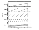
次に、バルブ6,7を閉じるとともにバルブ4を開放してCO2を流し、CO2の圧力が所定時間で60kPaになるように徐々に上昇させる。
CO2の圧力が60kPaに到達したら、バルブ4,7を閉じるとともにバルブ6を開放して、反応管を20秒間真空引きし、内部が20Pa以下になるようにする。
その後、再度CO2の圧力が所定時間で60kPaになるように徐々に上昇させる工程と、20秒間真空引きして20Pa以下になるようにする工程とを所定回数繰り返し、合計時間が120分になったら終了する。
最後に、バルブ6を閉じるとともにバルブ4,7を開放し、Arのみを流しながら、室温になるまで冷却する。
次に、バルブ6,7を閉じるとともにバルブ4を開放してCO2を流し、CO2の圧力が所定時間で60kPaになるように徐々に上昇させる。
CO2の圧力が60kPaに到達したら、バルブ4,7を閉じるとともにバルブ6を開放して、反応管を20秒間真空引きし、内部が20Pa以下になるようにする。
その後、再度CO2の圧力が所定時間で60kPaになるように徐々に上昇させる工程と、20秒間真空引きして20Pa以下になるようにする工程とを所定回数繰り返し、合計時間が120分になったら終了する。
最後に、バルブ6を閉じるとともにバルブ4,7を開放し、Arのみを流しながら、室温になるまで冷却する。
<試験1>
図2に示すように、本発明の効果を検証する実験を行った。
炭素材料としては、粒状のやし殻活性炭を使用した。
実施例1として、6分間でCO2の分圧を60kPaまで上昇させ、真空引きする工程を20回行って活性炭を賦活した。
実施例2として、12分間でCO2の分圧を60kPaまで上昇させ、真空引きする工程を10回行って活性炭を賦活した。
実施例3として、24分間でCO2の分圧を60kPaまで上昇させ、真空引きする工程を5回行って活性炭を賦活した。
実施例4として、60分間でCO2の分圧を60kPaまで上昇させ、真空引きする工程を2回行って活性炭を賦活した。
実施例5として、120分間でCO2の分圧を60kPaまで上昇させ、真空引きする工程を1回行って活性炭を賦活した。
また、初期のやし殻活性炭に手を加えないものを比較例1とした。
図2に示すように、本発明の効果を検証する実験を行った。
炭素材料としては、粒状のやし殻活性炭を使用した。
実施例1として、6分間でCO2の分圧を60kPaまで上昇させ、真空引きする工程を20回行って活性炭を賦活した。
実施例2として、12分間でCO2の分圧を60kPaまで上昇させ、真空引きする工程を10回行って活性炭を賦活した。
実施例3として、24分間でCO2の分圧を60kPaまで上昇させ、真空引きする工程を5回行って活性炭を賦活した。
実施例4として、60分間でCO2の分圧を60kPaまで上昇させ、真空引きする工程を2回行って活性炭を賦活した。
実施例5として、120分間でCO2の分圧を60kPaまで上昇させ、真空引きする工程を1回行って活性炭を賦活した。
また、初期のやし殻活性炭に手を加えないものを比較例1とした。
次に、実施例1~5および比較例の活性炭の吸着性能を測定するため、N2(窒素)ガスを流した。
図3は、流したN2ガスの相対圧(P/P0)を横軸に示し、それぞれの活性炭1gあたりに吸着されたN2ガスの体積(cm3/g)を測定した結果を縦軸に示した吸着等温線である。
相対圧0.2~1.0の範囲において吸着したN2ガスは、比較例1では250cm3/g程度であった。
これに対し、実施例5では400cm3/g程度、実施例4では425cm3/g程度、実施例3では450cm3/g程度、実施例2では500cm3/g程度、実施例1では600cm3/g程度となった。
このように、圧力スイングによる賦活を行った実施例1~5は、吸着性能において、初期状態の比較例1を大きく上回っていることがわかった。
図3は、流したN2ガスの相対圧(P/P0)を横軸に示し、それぞれの活性炭1gあたりに吸着されたN2ガスの体積(cm3/g)を測定した結果を縦軸に示した吸着等温線である。
相対圧0.2~1.0の範囲において吸着したN2ガスは、比較例1では250cm3/g程度であった。
これに対し、実施例5では400cm3/g程度、実施例4では425cm3/g程度、実施例3では450cm3/g程度、実施例2では500cm3/g程度、実施例1では600cm3/g程度となった。
このように、圧力スイングによる賦活を行った実施例1~5は、吸着性能において、初期状態の比較例1を大きく上回っていることがわかった。
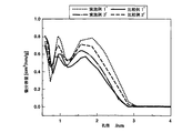
図4は、活性炭に形成された孔の径を横軸に示し、それぞれの活性炭1gあたりの所定径の孔の容量の総和を示した細孔径分布図である。
これによれば、径が1nm未満の孔および径が2.5nm超の孔では、縦軸において実施例1、実施例3、実施例5、比較例1にほとんど差がなかったが、径が1~2.5nmの孔では、縦軸において実施例1、実施例3、実施例5が比較例1を上回っていることがわかった。
すなわち、実施例1、実施例3、実施例5では、比較例1に比較して、微細な径の孔が多数形成されているか、あるいは微細な径の孔が深く形成されていることがわかった。
これによれば、径が1nm未満の孔および径が2.5nm超の孔では、縦軸において実施例1、実施例3、実施例5、比較例1にほとんど差がなかったが、径が1~2.5nmの孔では、縦軸において実施例1、実施例3、実施例5が比較例1を上回っていることがわかった。
すなわち、実施例1、実施例3、実施例5では、比較例1に比較して、微細な径の孔が多数形成されているか、あるいは微細な径の孔が深く形成されていることがわかった。
また、図5において、Sαsはαsプロット法によって求めた比表面積(m2/g)、Vmicroはαsプロット法によって求めたミクロ孔容積(cm3/g)、wは平均細孔径(nm)、burn offは重量減少率(%)を示している。
これによれば、圧力スイングの回数を増やすほど、比表面積やミクロ孔容積が増え、活性炭の吸着性能が向上することがわかった。
これによれば、圧力スイングの回数を増やすほど、比表面積やミクロ孔容積が増え、活性炭の吸着性能が向上することがわかった。
このように、本発明によって活性炭の微細な孔、比表面積やミクロ孔容積を増大させることができる理由は、圧力スイングの回数を増やすことによってCO2が活性炭内部に拡散しやすくなり、賦活を促進するためと考えられる。
<試験2>
次に、比較例2として、CO2の流量を徐々に上昇させる実施例5とは異なり、CO2の流量を開始から120分間48mL/minに保って1123Kで活性炭を賦活した。
また、比較例3として、温度を1143Kに変更したほかは比較例2と同様の条件で活性炭を賦活した。
なお、本発明の実施例1で流されるCO2の流量を平均すると48mL/minとなる。
次に、比較例2として、CO2の流量を徐々に上昇させる実施例5とは異なり、CO2の流量を開始から120分間48mL/minに保って1123Kで活性炭を賦活した。
また、比較例3として、温度を1143Kに変更したほかは比較例2と同様の条件で活性炭を賦活した。
なお、本発明の実施例1で流されるCO2の流量を平均すると48mL/minとなる。
初期状態の活性炭である比較例1と、比較例2,3と、本発明の実施例1とを比較した。
図6は、流したN2ガスの相対圧(P/P0)を横軸に示し、それぞれの活性炭1gあたりに吸着されたN2ガスの体積(cm3/g)を測定した結果を縦軸に示した吸着等温線である。
相対圧0.0~1.0の範囲において吸着したN2ガスは、比較例1では250cm3/g程度、比較例2では525cm3/g程度、比較例3では550cm3/g程度、実施例1では600cm3/g程度となった。
このように、圧力スイングによる賦活を行った実施例1は、CO2の流量を同じにした比較例2,3に比較しても、吸着性能が向上していることがわかった。
図6は、流したN2ガスの相対圧(P/P0)を横軸に示し、それぞれの活性炭1gあたりに吸着されたN2ガスの体積(cm3/g)を測定した結果を縦軸に示した吸着等温線である。
相対圧0.0~1.0の範囲において吸着したN2ガスは、比較例1では250cm3/g程度、比較例2では525cm3/g程度、比較例3では550cm3/g程度、実施例1では600cm3/g程度となった。
このように、圧力スイングによる賦活を行った実施例1は、CO2の流量を同じにした比較例2,3に比較しても、吸着性能が向上していることがわかった。
図7は、活性炭に形成された孔の径を横軸に示し、それぞれの活性炭1gあたりの所定径の孔の容量の総和を示した細孔径分布図である。
これによれば、径が0.5nm未満の孔および径が2.5nm超の孔では、縦軸において実施例1と、比較例2,3とにほとんど差がなかったが、径が0.5~2.0nmの孔では、縦軸において実施例1が比較例2,3を上回っていることがわかった。
すなわち、実施例1では、CO2の流量が同じ比較例2,3に比較して、微細な径の孔が多数形成されているか、あるいは微細な径の孔が深く形成されていることがわかった。
これによれば、径が0.5nm未満の孔および径が2.5nm超の孔では、縦軸において実施例1と、比較例2,3とにほとんど差がなかったが、径が0.5~2.0nmの孔では、縦軸において実施例1が比較例2,3を上回っていることがわかった。
すなわち、実施例1では、CO2の流量が同じ比較例2,3に比較して、微細な径の孔が多数形成されているか、あるいは微細な径の孔が深く形成されていることがわかった。
また、図8において、Sαsはαsプロット法によって求めた比表面積(m2/g)、Vmicroはαsプロット法によって求めたミクロ孔容積(cm3/g)、wは平均細孔径(nm)、burn offは重量減少率(%)を示している。
これによれば、圧力スイングによる賦活を行った実施例1は、温度およびCO2の流量を同じにした比較例2に比較して、重量減少率はほとんど変わらないが、比表面積やミクロ孔容積が増え、活性炭の吸着性能が向上することがわかった。
また、比較例3は、比較例2と比較すると、温度を上げたことにより比表面積やミクロ孔容積が増えているが、酸化により重量が初期状態から71%も減少してしまう。
他方、実施例1は、比較例3よりも吸着性能が向上しているにもかかわらず、比較例3よりも重量減少率が小さく、歩留りがよくなっている。
これによれば、圧力スイングによる賦活を行った実施例1は、温度およびCO2の流量を同じにした比較例2に比較して、重量減少率はほとんど変わらないが、比表面積やミクロ孔容積が増え、活性炭の吸着性能が向上することがわかった。
また、比較例3は、比較例2と比較すると、温度を上げたことにより比表面積やミクロ孔容積が増えているが、酸化により重量が初期状態から71%も減少してしまう。
他方、実施例1は、比較例3よりも吸着性能が向上しているにもかかわらず、比較例3よりも重量減少率が小さく、歩留りがよくなっている。
<試験3>
また、活性炭繊維においても、粒状活性炭と同様の効果が生じるか、実験を行った。
この試験では、炭素材料として活性炭繊維を使用した。
実施例1'として、6分間でCO2の分圧を60kPaまで上昇させ、真空引きする工程を20回行って活性炭を賦活した。
実施例3'として、24分間でCO2の分圧を60kPaまで上昇させ、真空引きする工程を5回行って活性炭を賦活した。
従来の賦活方法による比較例2'として、CO2の流量を開始から120分間48mL/minに保って1123Kで活性炭を賦活した。
また、初期の活性炭繊維に手を加えないものを比較例1'とした。
また、活性炭繊維においても、粒状活性炭と同様の効果が生じるか、実験を行った。
この試験では、炭素材料として活性炭繊維を使用した。
実施例1'として、6分間でCO2の分圧を60kPaまで上昇させ、真空引きする工程を20回行って活性炭を賦活した。
実施例3'として、24分間でCO2の分圧を60kPaまで上昇させ、真空引きする工程を5回行って活性炭を賦活した。
従来の賦活方法による比較例2'として、CO2の流量を開始から120分間48mL/minに保って1123Kで活性炭を賦活した。
また、初期の活性炭繊維に手を加えないものを比較例1'とした。
次に、実施例および比較例の活性炭の吸着性能を測定するため、N2(窒素)ガスを流した。
図9は、流したN2ガスの相対圧(P/P0)を横軸に示し、それぞれの活性炭1gあたりに吸着されたN2ガスの体積(cm3/g)を測定した結果を縦軸に示した吸着等温線である。
相対圧0.0~1.0の範囲において吸着したN2ガスは、比較例1'では550cm3/g程度であるのに対し、比較例2'では750cm3/g程度となった。
また、実施例3'では700cm3/g程度、実施例1'では850cm3/g程度となった。
図9は、流したN2ガスの相対圧(P/P0)を横軸に示し、それぞれの活性炭1gあたりに吸着されたN2ガスの体積(cm3/g)を測定した結果を縦軸に示した吸着等温線である。
相対圧0.0~1.0の範囲において吸着したN2ガスは、比較例1'では550cm3/g程度であるのに対し、比較例2'では750cm3/g程度となった。
また、実施例3'では700cm3/g程度、実施例1'では850cm3/g程度となった。
図10は、活性炭に形成された孔の径を横軸に示し、それぞれの活性炭1gあたりの所定径の孔の容量の総和を示した細孔径分布図である。
これによれば、径が0.5nm未満の孔では、縦軸において実施例3'、比較例1'、比較例2'にほとんど差がなかったが、実施例1'はこれらを下回っていた。径が0.5~3nmの孔では、縦軸において実施例1'が比較例1'、比較例2'を上回るとともに、実施例3'は比較例1'を上回るが比較例2'を下回っていることがわかった。径が3nm超の孔では、縦軸において実施例1'、実施例3'、比較例1'、比較例2'にほとんど差はなかった。
これによれば、径が0.5nm未満の孔では、縦軸において実施例3'、比較例1'、比較例2'にほとんど差がなかったが、実施例1'はこれらを下回っていた。径が0.5~3nmの孔では、縦軸において実施例1'が比較例1'、比較例2'を上回るとともに、実施例3'は比較例1'を上回るが比較例2'を下回っていることがわかった。径が3nm超の孔では、縦軸において実施例1'、実施例3'、比較例1'、比較例2'にほとんど差はなかった。
また、図11において、Sαsはαsプロット法によって求めた比表面積(m2/g)、Vmicroはαsプロット法によって求めたミクロ孔容積(cm3/g)、wは平均細孔径(nm)、burn offは重量減少率(%)を示している。
これによれば、実施例1'は、温度およびCO2の流量を同じにした比較例2'に比較して、重量減少率はほとんど変わらないが、比表面積やミクロ孔容積において比較例2'を上回っていることがわかった。
また、実施例3'は、比表面積やミクロ孔容積において比較例2'を下回っているが、重量減少率が比較例2'よりも小さくなっている。
これによれば、実施例1'は、温度およびCO2の流量を同じにした比較例2'に比較して、重量減少率はほとんど変わらないが、比表面積やミクロ孔容積において比較例2'を上回っていることがわかった。
また、実施例3'は、比表面積やミクロ孔容積において比較例2'を下回っているが、重量減少率が比較例2'よりも小さくなっている。
以上から、圧力スイングを行った実施例1',3'は、吸着性能において、初期状態の比較例1'を大きく上回っていることがわかった。
また、圧力スイングを5回行った実施例3'は、1gあたりの吸着量においては比較例2'を下回っている。しかし、比較例2'の重量減少率が51%であるのに対し、実施例3'の重量減少率は32%であり歩留りに優れるから、総合的な吸着性能では実施例3'が比較例2'を上回っている。
さらに、圧力スイングを20回行った実施例1'は、比較例2'に対して、吸着性能において優れるとともに、重量減少率が小さく歩留りにも優れていることがわかった。
また、圧力スイングを5回行った実施例3'は、1gあたりの吸着量においては比較例2'を下回っている。しかし、比較例2'の重量減少率が51%であるのに対し、実施例3'の重量減少率は32%であり歩留りに優れるから、総合的な吸着性能では実施例3'が比較例2'を上回っている。
さらに、圧力スイングを20回行った実施例1'は、比較例2'に対して、吸着性能において優れるとともに、重量減少率が小さく歩留りにも優れていることがわかった。
図12は活性炭の表面を撮影したSEM画像であって、(a)は未処理の粒状やし殻活性炭である比較例1を、(b)は圧力スイングを20回繰り返した粒状やし殻活性炭である実施例1を、(c)はCO2の流量を開始から120分間48mL/minに保って1123Kで賦活した粒状やし殻活性炭である比較例2を、(d)は未処理の活性炭繊維である比較例1'を、(e)は圧力スイングを20回繰り返した活性炭繊維である実施例1'を、(f)はCO2の流量を開始から120分間48mL/minに保って1123Kで賦活した活性炭繊維である比較例2'を、それぞれ示している。
図12はμmサイズの画像であるため、(a)と(b)とではほとんど差異がなく、(d)と(e)とでもほとんど差異がない。これは、上記の試験からわかるように、圧力スイングで活性炭を賦活した実施例1,1'では、活性炭にnmサイズの孔が多数形成されるためである。
他方、(c)は(a)(b)に比べて粒状やし殻活性炭に大きな窪みが形成されていることがわかる。また、(f)も、(d)(e)に比べて活性炭繊維に大きな窪みが形成されていることがわかる。すなわち、CO2の流量を開始時から一定に保つ従来の賦活方法では、大きすぎる孔が形成されてしまい、比表面積および吸着性能がそれほど大きくならず、かつ、重量が大きく減少してしまうことがわかる。
図12はμmサイズの画像であるため、(a)と(b)とではほとんど差異がなく、(d)と(e)とでもほとんど差異がない。これは、上記の試験からわかるように、圧力スイングで活性炭を賦活した実施例1,1'では、活性炭にnmサイズの孔が多数形成されるためである。
他方、(c)は(a)(b)に比べて粒状やし殻活性炭に大きな窪みが形成されていることがわかる。また、(f)も、(d)(e)に比べて活性炭繊維に大きな窪みが形成されていることがわかる。すなわち、CO2の流量を開始時から一定に保つ従来の賦活方法では、大きすぎる孔が形成されてしまい、比表面積および吸着性能がそれほど大きくならず、かつ、重量が大きく減少してしまうことがわかる。
1 活性炭
2 反応管
3 流量計
4 バルブ
5 圧力計
6 バルブ
7 バルブ
2 反応管
3 流量計
4 バルブ
5 圧力計
6 バルブ
7 バルブ
Claims (1)
- 炭素材料にCO2ガスを反応させて、炭素材料に微細な孔を形成する炭素材料の賦活方法であって、
炭素材料に接触するCO2ガスの圧力が所定時間で所定の大きさになるように徐々に上昇させる第一工程と、
炭素材料に接触するCO2ガスの圧力を所定の大きさまで減圧する第二工程とを、
少なくとも1回ずつ行うことを特徴とする炭素材料の賦活方法。
Applications Claiming Priority (2)
| Application Number | Priority Date | Filing Date | Title |
|---|---|---|---|
| JP2015092718A JP2016210631A (ja) | 2015-04-30 | 2015-04-30 | 炭素材料の賦活方法 |
| JP2015-092718 | 2015-04-30 |
Publications (1)
| Publication Number | Publication Date |
|---|---|
| WO2016175201A1 true WO2016175201A1 (ja) | 2016-11-03 |
Family
ID=57198601
Family Applications (1)
| Application Number | Title | Priority Date | Filing Date |
|---|---|---|---|
| PCT/JP2016/063033 Ceased WO2016175201A1 (ja) | 2015-04-30 | 2016-04-26 | 炭素材料の賦活方法 |
Country Status (2)
| Country | Link |
|---|---|
| JP (1) | JP2016210631A (ja) |
| WO (1) | WO2016175201A1 (ja) |
Cited By (1)
| Publication number | Priority date | Publication date | Assignee | Title |
|---|---|---|---|---|
| WO2024195788A1 (ja) * | 2023-03-23 | 2024-09-26 | 出光興産株式会社 | 複合体、正極合材、リチウムイオン電池用正極、リチウムイオン電池、複合体の製造方法、活性炭の使用及び活性炭の製造方法 |
Families Citing this family (2)
| Publication number | Priority date | Publication date | Assignee | Title |
|---|---|---|---|---|
| JP7582615B2 (ja) * | 2020-02-14 | 2024-11-13 | 国立研究開発法人産業技術総合研究所 | ペル及びポリフルオロアルキル化合物捕集個人曝露測定用サンプラー |
| TWI859415B (zh) * | 2020-02-14 | 2024-10-21 | 國立研究開發法人產業技術總合研究所 | 用於收集全氟及多氟烷基化合物之個人暴露測量用採樣器 |
Citations (2)
| Publication number | Priority date | Publication date | Assignee | Title |
|---|---|---|---|---|
| JPH0280621A (ja) * | 1988-09-13 | 1990-03-20 | Nippon Steel Corp | フェルト状活性炭素繊維の賦活方法および装置 |
| JP2002356318A (ja) * | 2001-05-31 | 2002-12-13 | Inoac Corp | 活性炭多孔体の製造方法 |
-
2015
- 2015-04-30 JP JP2015092718A patent/JP2016210631A/ja active Pending
-
2016
- 2016-04-26 WO PCT/JP2016/063033 patent/WO2016175201A1/ja not_active Ceased
Patent Citations (2)
| Publication number | Priority date | Publication date | Assignee | Title |
|---|---|---|---|---|
| JPH0280621A (ja) * | 1988-09-13 | 1990-03-20 | Nippon Steel Corp | フェルト状活性炭素繊維の賦活方法および装置 |
| JP2002356318A (ja) * | 2001-05-31 | 2002-12-13 | Inoac Corp | 活性炭多孔体の製造方法 |
Non-Patent Citations (1)
| Title |
|---|
| WANG, SHUWEN ET AL.: "CO2-pressure swing activation for efficient production of highly porous carbons", CARBON, vol. 85, 13 January 2015 (2015-01-13), pages 245 - 248, XP029195232 * |
Cited By (1)
| Publication number | Priority date | Publication date | Assignee | Title |
|---|---|---|---|---|
| WO2024195788A1 (ja) * | 2023-03-23 | 2024-09-26 | 出光興産株式会社 | 複合体、正極合材、リチウムイオン電池用正極、リチウムイオン電池、複合体の製造方法、活性炭の使用及び活性炭の製造方法 |
Also Published As
| Publication number | Publication date |
|---|---|
| JP2016210631A (ja) | 2016-12-15 |
Similar Documents
| Publication | Publication Date | Title |
|---|---|---|
| US10105680B2 (en) | Activated carbon with excellent adsorption performance and process for producing same | |
| JP5902920B2 (ja) | 窒素ガス製造方法、ガス分離方法および窒素ガス製造装置 | |
| Hu et al. | Straightforward synthesis of a triazine-based porous carbon with high gas-uptake capacities | |
| JP6379324B1 (ja) | 活性炭及びその製造方法 | |
| JPH0751551A (ja) | 制御された気孔を有する炭素薄膜の製造方法 | |
| JP7131543B2 (ja) | 表面処理された炭素ナノ構造体の製造方法 | |
| WO2016175201A1 (ja) | 炭素材料の賦活方法 | |
| Hong et al. | Preparation of porous carbons based on polyvinylidene fluoride for CO2 adsorption: A combined experimental and computational study | |
| JPH05161843A (ja) | 炭酸ガス吸着剤 | |
| Zielinska et al. | Pd supported ordered mesoporous hollow carbon spheres (OMHCS) for hydrogen storage | |
| WO2015033643A1 (ja) | 多孔質炭素、調湿吸着材、吸着式ヒートポンプ、及び燃料電池 | |
| WO2013114637A1 (ja) | 窒素富化ガス製造方法、ガス分離方法および窒素富化ガス製造装置 | |
| JP2013056810A (ja) | オゾンガスの濃縮方法及びその装置 | |
| JPWO2015152391A1 (ja) | 浄水器用活性炭 | |
| CN109499527B (zh) | 一种Ca2+和Ag+改性吸附材料及其制备方法与应用 | |
| JP6402008B2 (ja) | 疎水性活性炭及びその製造方法 | |
| JP6757705B2 (ja) | メタン吸蔵用球状フェノール樹脂活性炭、及びその製造方法、並びに該活性炭を用いたメタン吸蔵材、及び該活性炭を用いたメタン吸蔵方法 | |
| KR102614590B1 (ko) | 화학안정화된 바이오매스 기반 고비표면적 활성탄소 및 이의 제조방법 | |
| CN114288810A (zh) | 微孔碳材料在吸附分离烯烃和烷烃中的应用 | |
| WO2017092242A1 (zh) | 吸音材料颗粒的制备方法和吸音材料颗粒 | |
| JP2009154079A (ja) | ガス製造装置の停止方法 | |
| KR101626744B1 (ko) | 초다공성 그라핀 에어로젤 및 그 제조방법 | |
| JP2015057373A (ja) | 多孔質炭素及びその製造方法 | |
| JP6483477B2 (ja) | カルシウム塩の製造方法及び炭素多孔体の製造方法 | |
| KR101885249B1 (ko) | 활성탄의 제조 방법 |
Legal Events
| Date | Code | Title | Description |
|---|---|---|---|
| 121 | Ep: the epo has been informed by wipo that ep was designated in this application |
Ref document number: 16786478 Country of ref document: EP Kind code of ref document: A1 |
|
| NENP | Non-entry into the national phase |
Ref country code: DE |
|
| 122 | Ep: pct application non-entry in european phase |
Ref document number: 16786478 Country of ref document: EP Kind code of ref document: A1 |