WO2016175188A1 - 遊星ローラ駆動型内接式遊星歯車減速装置 - Google Patents
遊星ローラ駆動型内接式遊星歯車減速装置 Download PDFInfo
- Publication number
- WO2016175188A1 WO2016175188A1 PCT/JP2016/062988 JP2016062988W WO2016175188A1 WO 2016175188 A1 WO2016175188 A1 WO 2016175188A1 JP 2016062988 W JP2016062988 W JP 2016062988W WO 2016175188 A1 WO2016175188 A1 WO 2016175188A1
- Authority
- WO
- WIPO (PCT)
- Prior art keywords
- planetary
- gear
- planetary gear
- planetary roller
- inscribed
- Prior art date
Links
Images


Classifications
-
- F—MECHANICAL ENGINEERING; LIGHTING; HEATING; WEAPONS; BLASTING
- F16—ENGINEERING ELEMENTS AND UNITS; GENERAL MEASURES FOR PRODUCING AND MAINTAINING EFFECTIVE FUNCTIONING OF MACHINES OR INSTALLATIONS; THERMAL INSULATION IN GENERAL
- F16H—GEARING
- F16H1/00—Toothed gearings for conveying rotary motion
- F16H1/28—Toothed gearings for conveying rotary motion with gears having orbital motion
- F16H1/32—Toothed gearings for conveying rotary motion with gears having orbital motion in which the central axis of the gearing lies inside the periphery of an orbital gear
Definitions
- the present invention uses a planetary roller in place of the eccentric body to transmit power from an eccentric body connected to the input shaft of the inscribed planetary gear speed reducer to the planetary gear.
- the planetary gear can be used as a pressurizing mechanism for the planetary roller while facilitating power transmission from the planetary roller, and the inscribed planetary gear reduction device and the planetary roller are integrated in a small size and
- the present invention relates to a quiet, planetary roller drive type inscribed planetary gear reduction device.
- a communication robot using a relatively small pan head that operates to follow a target for the purpose of voice recording or image recognition, or a stuffed toy that can be held by hand.
- a radio control model or the like requires a quiet, low-vibration actuator that is smaller and lighter, and a reduction gear used for these needs to be low-vibration, low-noise, small and lightweight. Has been.
- spur gears and planetary gears used for such small motor speed reducers for relatively small actuators have the disadvantage of high noise, and when using worm wheels instead of these, The noise is small, but the size is large.
- a planetary gear speed reducer equipped with a planetary gear mechanism may be used as a speed reducer used for a small motor as described above.
- the planetary gear speed reducer for example, as shown in FIG. 14 (A), an internal gear S, a planetary gear P, and a drive shaft C are used, and an output is extracted from the output shaft O.
- a cycloid speed reducer such as “Cyclo Speed Reducer (registered trademark)”.
- the cycloid reduction gear is driven by an eccentric body E connected to a drive shaft C from a motor serving as a drive source (not shown), and the peripheral body driven by the eccentric body E.
- a curved plate P having an external gear
- a frame member S ′ having an external pin Sp functioning as a fixed internal gear that circumscribes the curved plate P
- an internal pin Op inserted through the curved plate P.
- the output shaft O is the main component.
- the eccentric body E is a cam provided eccentrically with respect to the drive shaft C, and a part of the cam circumscribes an eccentric in-vivo contact PH provided at the center of the curved plate P, and
- the curved plate P is revolved within the frame of the fixed internal gear constituted by the outer pin Sp by rotating around the axis of the drive shaft C inside the eccentric body-inscribed portion PH by the drive shaft C. Only the rotation component of the curved plate P by the inner pin Op provided on the output shaft O through the inner pin inscribed portions Ph arranged at equal intervals from the center of the curved plate P. Is extracted to the transmission shaft Os to reduce the rotational speed from the drive shaft and adjust the torque.
- Patent Document 1 Japanese Patent No. 2739071
- an eccentric body such as a cam is directly driven by a motor by a driving force of a small motor or the like, thereby driving a curved plate.
- Patent Document 2 Japanese Patent Laid-Open No. 6-341501
- Patent Document 2 requires a pressurizing mechanism, and the pressurizing mechanism is complicated. Therefore, a small motor or the like is used as a drive source. It has become difficult to apply to the reducer that does.
- Patent Document 2 the invention described in Patent Document 2 is configured so that a pressure contact force for friction drive transmission is generated by elastic deformation of the inner roller 28 having two groove-shaped cross sections.
- the inner roller 28 of the above-mentioned patent document 2 has a bearing 26 between the casing 11 and the cover 25. It is provided in contact with the end face so as to be clamped together with the bearing stand 27 to be supported.
- the roller 28 is mounted by attaching the cover 25 to the casing 11 with the fastening bolt 24, and the inner roller 28 sandwiched between the cover 25 and the casing 11 is pushed in the axial direction.
- the width of the roller 28 is elastically pressed and its inner peripheral surface reduces its radius while forming a crowning deformation.
- Patent Document 2 For a reduction gear that uses a relatively small motor as a drive source. There has been a problem in realizing a reduction gear that can be used in a reduction gear for a small motor having a diameter of about 10 to 20 mm and is quiet, small, and low in cost with a reduction ratio of about 50 to 200.
- the present invention is intended to solve the above-described problems, and relates to a reduction gear (speed reduction device) using the above inscribed planetary gear, and is smaller, lighter, and lower in vibration and noise than in the past. It is an object of the present invention to provide an inscribed planetary gear reduction device with low cost.
- the present invention is provided such that an input shaft connected to a driving source and rotating around an axis, and an outer peripheral surface of the input shaft and a part of the rotating surface are in contact with each other.
- a planetary roller having a rotating shaft parallel to the axis of the input shaft and facing the same direction, a disk-shaped transmission plate formed perpendicular to the input shaft, and an outer edge of the transmission plate from the drive source
- An outer ring formed parallel to the input shaft on the side, and the transmission plate has a plurality of through holes formed at equal intervals so as to surround the center of the transmission plate, Part of the rotating surface of the planetary roller is inscribed on the inner surface, and meshes with a planetary gear having an inner gear formed on the outer surface of the outer ring and an inner gear formed on the outer surface of the outer ring of the planetary gear.
- An output shaft comprising a transmission plate in which a plurality of pins that are partially inscribed in each of the holes and a transmission shaft that is erected on a side opposite to the side on which the pins of the transmission plate are erected,
- the planetary roller drive type inscribed planetary gear speed reduction device is provided.
- the rotating surface of the planetary roller is made of an elastic body, or a part of the outer gear of the frame member facing the inner gear is a shaft of the drive source.
- a rotatable pin having a rotation axis parallel to the center, or by forming the tooth profile of the internal gear on the outer surface of the planetary gear by either an involute tooth profile or a cycloid tooth profile. Can be achieved more effectively.
- the eccentric body required for the conventional inscribed planetary gear reduction device is configured as a planetary roller, both quietness and miniaturization are achieved, and the number of parts is further reduced. It is also possible to decrease.
- the planetary roller mechanism requires a preload according to the output torque, but this mechanism acts on the planetary roller according to the output torque, so when the input / output torque is small, the preload is small and large.
- the preload also increases. For this reason, when the input / output torque is small, the loss caused by the deformation of the planetary roller due to the preload is small, and when the input / output torque is large, the preload is large and a large torque can be transmitted.
- the magnitude of the preload per output torque can be adjusted by the design of the planetary gear.
- an inscribed planetary gear reduction device that is smaller, lighter, and lower in cost, lower in vibration and lower in noise than in the past.
- FIG. 7E is a top view showing another configuration example of the counterweight
- 5F is a top view showing another configuration example of the planetary roller unit.
- (A) is a top view of the planetary gear
- (B) is a side sectional view taken along line AA of (A).
- (A) is a top view of the frame member
- (B) is a side view thereof
- (C) is a top view showing another configuration example of the external gear of the frame member.
- (A) is a top view of the output shaft
- (B) is a side view thereof
- (C) is a bottom view thereof
- (D) is a perspective view thereof.
- (A) is a cross-sectional view of the cross section taken along the line AA shown in FIG.
- FIG. 10 is a diagram showing a planetary gear in the configuration example shown in FIG.
- FIG. 10 is a diagram showing an output shaft in the configuration example shown in FIG. 9, wherein (A) is a perspective view, (B) is a top view, (C) is a side view, and (D) is AA in FIG. It is sectional drawing in a line.
- A) is a mechanism figure of the conventional planetary gear mechanism
- B) is a perspective view of the conventional cycloid reduction mechanism.
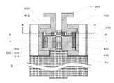
- FIG. 1 is a perspective view showing main components according to an embodiment of the present invention. In the above embodiment of the present invention, these components are combined as shown in the side cross section in FIG. 2 and function as a speed reducer.
- the input shaft C connected to the drive source PU and rotating around the axis is in contact with the side surface of the input shaft C.
- the output shaft 600 for output is a main component.
- the planetary roller 300 is configured as a part of the planetary roller unit 350 in this embodiment, and the planetary roller unit 350 is generally shown in a top view in FIG. It has a form based on a substantially circular plate as shown in a side view in FIG. Note that FIG. 3B also shows a side cross section (portion where hatching is displayed) of a part of the planetary roller 300 as viewed from the AA direction in FIG.
- the planetary roller unit 350 includes a base material 351 made of a disk-shaped engineering plastic or the like, and a planetary roller 300 and a counterweight 353 arranged on the plate surface of the base material 351.
- a through hole 355 through which the input shaft C from the drive source PU passes through the plate surface of the base 351 vertically is provided at the center of the base 351.
- the planetary roller 300 and the counterweight 353 are The through hole 355 is arranged such that its center of gravity is substantially the position of the contrast when viewed from above.
- the diameter of the disk-shaped base material 351 is smaller than the diameter of a circle formed by the inner surface of the outer ring 430 of the planetary gear 400 described later.
- the planetary roller 300 has a generally cylindrical shape with a central axis 310 standing on the plate surface of the base material 351 as a main axis, and is rotatable around the central axis 310.
- a central axis 310 standing on the plate surface of the base material 351 as a main axis, and is rotatable around the central axis 310.
- a ring body 330 made of a metal material such as duralumin
- a contact band 340 made of an elastic body such as an elastomer such as urethane rubber provided around the ring body 330.
- the central axis 310 is located at a position away from the center of the plate surface of the base material 351, and is input to the through hole 355 at the center of the base material 351 in a direction perpendicular to the plate surface of the base material 351.
- the rotating surface of the planetary roller 300 that is parallel to the direction of the axis of the input shaft C and faces the same direction is the outer edge of the contact band 340.
- the main shaft of the central shaft 310 has the erected portion from the base material 351 as a fulcrum. It is desirable to have a certain degree of elasticity in the vertical direction from the main axis toward the upper end.
- the counterweight 353 is erected on the same surface of the base 351 as the planetary roller 300, and surrounds the half side surface of the input shaft C at the string portion with the through hole 355 as the center. It is formed in a semicircular shape so as not to cause interference such as contact with the planetary gear 400 described later, and is basically made of the same material as the base material 351.
- the planetary roller unit 350 configured as described above passes the input shaft C through the through-hole 355, and a contact band 340 constituting a part of the outer surface of the inserted input shaft C and the rotation surface of the planetary roller 300.
- a contact band 340 constituting a part of the outer surface of the inserted input shaft C and the rotation surface of the planetary roller 300.
- the planetary gear 400 is powered by bringing the side surface opposite to the input shaft C of the contact band 340 constituting the rotating surface of the planetary roller 300 into contact with the inner side surface of the outer ring 430 of the planetary gear 400 described later. Can be transmitted.
- the planetary roller unit 350 is composed of the plate surface of the disk-shaped base material 351 and the planetary roller 300 and the counterweight 353 arranged on the plate surface.
- the planetary roller unit 350 is not limited to the above-described configuration, and any configuration is possible as long as the planetary roller 300 can be rotated in contact with the outer surface of the input shaft C.
- the present invention is not limited to those based on the disk shape as described above.
- the planetary roller 300 basically includes the central shaft 310, the ring body 330, and the contact zone 340 as described above.
- the configuration of the planetary roller 300 is not limited thereto, and power can be transmitted from the input shaft C.
- the shaft center of the central shaft 310 has a certain degree of elasticity with a contact portion with the base material 351 as a fulcrum. If so, there is no particular limitation. Therefore, for example, as shown in FIG.
- the ring body 330 and the contact band 340 are integrally formed from an elastic part 370 such as an elastomer made of rubber or the like, or the center shaft 310 and the ring
- an elastic part 370 such as an elastomer made of rubber or the like
- another configuration is adopted in consideration of the frictional force and force transmission efficiency of the planetary roller, such as providing a contact band support ring 390 as shown in FIG. Is also possible.
- the counterweight 353 is intended to suppress vibration by adjusting the mass balance around the input shaft C when the planetary roller 300 is rotated in contact with the outer surface of the input shaft C. Is. Therefore, if the above purpose is achieved, the configuration is not limited to the above form.
- the configuration is not limited to the above form.
- it is configured as an annular ring surrounding the periphery of the through hole 355, and the common center of gravity of the counterweight 353 and the planetary rotor 300 is near the center of the through hole 355 in a top view. You may comprise as follows.
- the present invention is assumed to be used exclusively as a speed reducer using a small drive source, when the planetary roller 300 can be reduced in weight using a small electric motor or the like as the drive source, In some cases, the counterweight 353 is not necessarily provided.
- the base shaft 351 of the planetary roller unit 350 has a substantially fan shape without providing the counterweight 353, and the input shaft
- the planetary roller 300 may be held around C.
- the input shaft C that makes the side surface contact the planetary roller 300 is generally made of metal. Therefore, in order to improve the power transmission efficiency of the contact portion with the planetary roller 300, the portion where the input shaft C is in contact with the planetary roller 300 is subjected to surface treatment such as coating or the portion of the input shaft C. It is also possible to increase the frictional force from the input shaft C to the planetary roller 300 by attaching a thin film made of an elastic body around the shaft.
- the planetary gear 400 includes a top view in FIG. 4 (A) and a side sectional view as seen from the direction AA in FIG. 4 (A).
- a transmission plate 410 which is a circular flat plate
- an outer ring 430 having an internal gear 433 on the outer side is provided so as to surround the periphery. It is comprised by the annular
- the side not sealed with the transmission plate 410 among the above-described annular components is arranged so as to come to the input shaft C side (drive source PU side) when combined with other components. Established.
- the outer diameter of the circular flat plate constituting the transmission plate 410 is formed in consideration of the size of the circumference formed by the external gear 533 formed on the frame member 500 described later. This is because when the diameter of the transmission plate 410 of the planetary gear 400 is made too large so that the eccentricity with respect to the center of the circumference formed by the external gear 533 formed on the frame member 500 is reduced, the planetary gear 400 is used. This is because the planetary motion of can not be. Therefore, the diameter of the circular flat plate that constitutes the transmission plate 410 is such that the planetary gear 400 sequentially moves in planetary motion while meshing with the external gear 533 formed on the frame member 500 by the movement of the planetary roller 300. Is adjusted to the possible range.
- a circular central through hole 415 (not essential) is provided at the center of the transmission plate 410 when viewed from the top surface that vertically penetrates the plate surface of the transmission plate 410, and further surrounds the periphery thereof.
- a plurality of circular inner pin inscribed portions 413 that are circular as viewed from above are provided on the circumference of the transmission plate 410 so as to vertically pass through the plate surface at equal intervals.
- the inner pin inscribed portion 413 is an inner pin provided on an output shaft 600 (to be described later) when the planetary gear 400 performs a planetary motion (rotation) within a frame of an outer gear 533 of the frame 500 (to be described later).
- the object is to circulate the inner peripheral surface of the inner pin inscribed portion 413, which is the circular through hole, while contacting a part of the pin 610. Therefore, the size of the circle constituting the inner pin inscribed portion 413 is determined in consideration of the rotation area of the planetary gear 400 in the frame 500, the size of the inner pin 610, and the like.
- the inner surface of the outer ring 430 is formed as a smooth surface having an appropriate friction coefficient so that the outer peripheral surface of the planetary roller 300 can be contacted and rotated to transmit power.
- the diameter of the circle formed by the inner surface of the outer ring 430 is a radius of the input shaft C so that the planetary roller 300 can be rotated along the inner surface while considering the outer diameter of the transmission plate 410. It is formed to be slightly larger than the size Rr in which Rc and the diameter of the planetary roller 300 are combined.
- an internal gear 433 is formed on the outer surface of the outer ring 430 along the circumferential direction of the outer ring 430.
- the tooth profile is not particularly limited as long as it can mesh with an external gear 533 of the frame 500 described later. Therefore, it may be an involute tooth profile or a cycloid tooth profile, or a tooth profile belonging to these systems but having an adjusted dislocation coefficient or any other tooth profile, or a combination thereof.
- the side surface of the rotation surface of the planetary roller 300 described above is inscribed in the inner surface of the outer ring 430 that configures the planetary gear 400, and further, the outer ring An inner gear 433 formed on the outer surface of the outer ring 430 and an outer gear 533 of the frame 500 described later mesh with each other on the outer surface side of the portion inscribed with the planetary roller 300. Therefore, if the power transmission from the planetary roller 300 to the planetary gear 400 is performed in this way, the form of the internal gear 433 formed on the planetary gear 400 and the external gear 533 of the frame 500 is not particularly limited. Not provided.
- the inner surface of the planetary gear 400 is pressed against the planetary roller 300, so that the internal gear 433 of the planetary gear 400 is one of the external gears 533 of the frame 500.
- the planetary gear 400 sequentially rotates in the outer gear 533 by the rotation of the planetary roller 300, the cycloid is brought into contact with the other portion while meshing only with the portion.
- a deceleration mechanism can be configured.
- the tooth pattern of the external gear 533 is composed of a similar curve that meshes with the above curve, and the number of teeth of the external gear 533 is n + 1 so that a large speed reduction is achieved while suppressing the interference of the tooth tips. It is also possible to obtain a ratio.
- the frame body 500 and the planetary gear 400 are also formed in a relatively small size, and the slipperiness of an elastomer such as plastic made of these materials is often good.
- the tooth profile is determined in consideration of the characteristics of equipment and materials used.
- the frame member 500 has a large through hole at the center as a whole as shown in a top view in FIG. 5 (A) and a side view in FIG. 5 (B).
- 530 and the small through-hole 550 adjacent to it are formed in the shape of a flat plate, and the material thereof is formed of engineering plastic or the like, similar to the base material 351 constituting the planetary roller unit 350.
- An outer gear 533 is formed on the inner peripheral surface of the large through-hole 530 in the central portion, and the planetary gear 400 moves while rotating in a substantially circumference formed by the outer gear 533. It has become.
- the two small through holes 550 provided adjacent to the large through hole 530 are for inserting screws (not shown) for fixing the frame member 500 to the drive source PU. Therefore, in the present embodiment, as illustrated in FIG. 1, each component of the present embodiment is accommodated between a later-described fixing plate 700 and the driving source PU, and the through-hole 550 is accommodated in the fixing plate 700.
- the components of the present invention can be functionally accommodated by inserting the screws in the direction of the drive source PU from the upper surface of the through-hole 750 provided in the same manner as above and screwing the screws to the drive source PU. Is possible.
- the external gear 533 formed on the inner peripheral surface of the large through hole 530 is formed so as to mesh with the internal gear 433 formed on the outer ring 430 of the planetary gear 400.
- the tooth profile of the external gear 533 is not particularly limited for the same reason as described above with respect to the internal gear 433, and therefore may be an involute tooth profile, a cycloid tooth profile, or another tooth profile.
- the number of teeth of the external gear 533 is at least one more than that of the internal gear 433 formed on the outer ring 430 of the planetary gear 400. As will be described later, the number of teeth of the planetary roller 300 and the input shaft C is increased. By considering the aperture ratio and the like together, it is possible to obtain a reduction ratio according to the difference.
- the outer gear 533 is not limited to the form in which the inner peripheral surface of the through hole 530 is formed as the involute tooth shape, the cycloid tooth shape, or other tooth shapes as described above, and a top view of a portion corresponding to FIG.
- a plurality of rollers (pins) 533R having a rotation axis parallel to the axis of the input shaft C and facing the same direction with respect to the contact portion of the inner surface of the external gear 533 with the planetary gear 400.
- You may comprise by. And especially when it is set as such a form, when using this invention for a cycloid reduction mechanism, the internal gear 433 formed in the said planetary gear 400 and the external gear 533 formed in the frame member 500 mesh. It is possible to reduce the resistance caused by the interference and tooth tip interference.
- the planetary gear 400 is sequentially meshed with the outer gear 533 along the inner side of the outer gear 533 that is formed in a substantially circumferential shape. It is possible to revolve while rotating, thereby facilitating extraction of output from the output shaft 600 described later.
- the output shaft 600 includes a top view in FIG. 6A, a side view in FIG. 6B, a bottom view in FIG. 6C, and a bottom view in FIG.
- a disc-shaped transmission plate 610, a plurality of cylindrical inner pins 630 erected from the transmission plate 610, and the inner pins 630 of the transmission plate 610 are erected.
- the transmission shaft is erected from the center of the opposite side of the plate surface, and the material thereof is formed of engineering plastic or the like, similar to the base material 351 and the frame member 500 constituting the planetary roller unit 350. Has been.
- the plurality of inner pins 630 are provided in the same number as the plurality of inner pin inscribed portions 413 provided on the planetary gear 400, and the inner pins 630 are centered on the center of the transmission plate 610. Are provided at equal intervals on the circumference. Further, the inner pin 630 basically has a cylindrical shape, and the length of the cylindrical portion of the cylindrical shape constituting the inner pin 630 is such that the output shaft 600 is connected to the planet as shown in FIG. When combined from above the gear 400, it is formed in such a length that it can be inscribed in the inner pin inscribed portion 413 formed on the planetary gear 400, and its diameter is in the inner pin provided in the planetary gear 400. It is formed to such an extent that it can circulate along the inner periphery of the contact portion 413.
- the transmission shaft 650 of the output shaft 600 is erected on the plate surface opposite to the side where the inner pin 630 is provided from the center of the shape of the disk forming the transmission plate 610,
- the shaft center of the transmission shaft 650 is arranged on an extension line concentric with the shaft center of the input shaft C when the components of the present invention are combined as shown in FIG.
- the output shaft 600 is configured as described above, so that the rotation and revolution motions of the planetary gear 400 are performed along the inner periphery of the inner pin inscribed portion 413 provided on the planetary gear 400. It is possible to take out only the rotation component by the inner pin 630 rotating around, and as a result, take out the output of the adjusted rotation speed and torque on the same axis as the input shaft C by the transmission shaft 650. Is possible.
- the output shaft 600 is for the purpose of extracting only the rotation motion from the planetary motion of the planetary gear 400, so that the output shaft 600 is not limited to the above as long as it has the same function. It is also possible.
- the fixing plate 700 and the spacer 790 are provided as described in FIG.
- the fixing plate 700 functionally accommodates each component of the present invention, and a through hole 730 is provided at the center and another through hole 750 is provided on the outer peripheral side of the through hole 730. It has a flat plate shape as a whole. And the material is comprised from engineering plastics etc. similarly to the said frame member 500 grade
- the transmission shaft 650 of the shaft 600 is configured to be inserted, but the transmission plate 610 of the output shaft 600 is configured not to be inserted.
- the spacer 790 is disposed between the upper surface side of the planetary roller unit 350 having the planetary roller 300 and the planetary gear 400 so that the two components can be smoothly moved. It is formed in a circular flat plate shape having a through hole in the center for assisting proper movement. However, in the above embodiment, the spacer 790 is disposed between the upper surface side of the planetary roller unit 350 and the planetary gear 400 as described above. You may arrange
- the spacer 790 is not necessarily an essential component of the present invention, the spacer 790 is omitted in consideration of the degree and size of the output of the drive source PU or the slipperiness (lubricity) of the engineering plastic used as a material. It is also possible.
- the drive source PU is not limited to this, and depending on the type of mechanical device such as an actuator that uses the speed reducer. Any selection is possible.
- the present invention provides a planetary roller drive type planetary gear speed reduction device that can realize a reduction in size because the preloading mechanism required for the conventional planetary roller mechanism can be omitted.
- the planetary roller mechanism requires a preload corresponding to the output torque.
- the preload corresponding to the output torque acts on the planetary roller.
- the preload decreases and increases, the preload increases.
- the magnitude of the preload per output torque can be adjusted by the design of the planetary gear.
- the planetary roller 300 that rotates in contact with the outer peripheral surface of the input shaft C and the outer periphery of the planetary roller 300 are described.
- a planetary gear 400 having an outer ring 430 rotating with a part of the surface inscribed therein, and an inner gear 433 formed on the outer surface of the outer ring 430 of the planetary gear 400 mesh with the planetary gear 400 along the inner circumference.
- Frame member 500 having an external gear 533 capable of performing planetary motion, and an output shaft 600 that can output only the rotational component extracted from the planetary motion of the planetary gear 400.
- the power transmitted as the rotation of the input shaft C from the drive source PU is provided inside the frame member 500 from the planetary roller 300 via the inner surface of the outer ring 430 of the planetary gear 400.
- the inner pin 630 provided on the output shaft 600 is converted into the planetary movement of the planetary gear 400 within the frame of the outer gear 533 and provided on the inner periphery of the inner pin inscribed portion 413 provided on the planetary gear 400.
- FIG. 7A is a cross-sectional view of the portion taken along the line AA in the side cross-sectional view shown in FIG. 2
- FIG. 3 is a cross-sectional view of a portion taken along line BB in the side cross-sectional view shown in FIG.
- FIG. 7B in order to facilitate understanding of the present invention, only the planetary gear 400 and the input shaft C are hatched, and the other parts are not shown.
- the radial force (arrow A in the figure) generated in the planetary gear 400 is used as a preload.
- the inner surface of the outer ring 430 of the planetary gear 400 is used as the outer roller of the planetary roller mechanism.
- the planetary roller 300 presses the planetary gear 400 against the external gear 533 formed inside the frame member 500 as shown in FIG. Accordingly, a radial force (arrow A in FIG. 7A) is generated, and this force is applied to the planetary roller 300 as indicated by arrow B in FIG. 7B.
- the reduction ratio by the planetary roller is such that the radius of the input shaft C is Rc and the rotation of the planetary roller 300 from the axis of the input shaft C is as shown in FIG.
- Rp the distance to the portion where the side surface of the planetary gear 400 contacts the inner surface of the outer ring 430 of the planetary gear 400 (where the contact portion does not slip)
- Rp the distance to the portion where the side surface of the planetary gear 400 contacts the inner surface of the outer ring 430 of the planetary gear 400 (where the contact portion does not slip)
- the reduction ratio between the planetary gear 400 and the frame member 500 is such that the number of teeth of the internal gear 433 formed on the outer ring 430 of the planetary gear 400 is Zc, as shown in FIG. Assuming that the number of teeth of 533 is Zd, it is as follows.
- n [(Rp / Rc) +1] ⁇ [Zc by (reduction ratio by the planetary roller) ⁇ (reduction ratio by the planetary gear 400 and the frame member 500). / (Zd-Zc)] is obtained.
- a small electric motor is used.
- n a reduction ratio n of approximately 119 is obtained.
- the above embodiment of the present invention shows an example of the configuration example of the present invention, and the present invention is not limited to the above example, and is within the scope equivalent to the basic components of the present invention. Naturally, modifications that can be implemented by a trader are also included in the present invention.
- the internal gear 433 formed on the planetary gear 400 and the external gear 533 formed on the frame 500 are partially engaged with each other, but are not in contact with each other.
- the planetary gear 800 is formed with an epitrochoid curve or the like as shown in FIGS. 8 (A) and 8 (B).
- FIG. 9 is a perspective view schematically showing different configuration examples of the planetary gear, the output shaft, and the frame member constituting the present invention as described above, and FIG. 10 shows a state in which these are combined. It is a sectional side view. Further, FIG. 9 shows a state in which some components are removed for easy understanding.
- FIG. 9 is a perspective view in FIG. 11 (A), a top view in FIG. 11 (B), a side view in FIG. 11 (C), and a line AA in FIG.
- a planetary gear 940 showing a sectional view, a perspective view in FIG. 12A, a top view in FIG. 12B, a frame member 950 as shown in a side view in FIG. 12C, and a perspective view in FIG. (B) is a top view, (C) is a side view, and (D) is a cross-sectional view taken along the line AA of FIG. is there.
- an outer ring 943 having gears with different numbers of teeth in two upper and lower stages composed of an upper stage 943U and a lower stage 943D on the outer surface of the planetary gear 940 shown in FIG. 11, which is a component of the present invention.
- the external gear 953 of the frame member 950 shown in FIG. 12 and the output shaft 960 in FIG. 13 are formed.
- the basic configuration of the planetary roller 300 of the present invention and the inner side surface of the planetary gear 940 have the same configuration as the above-described embodiment.
- the lower stage 943 ⁇ / b> D of the outer ring 943 of the planetary gear 940 corresponds to the frame member 950. It meshes with the inside of the external gear 953 formed inside and rotates within the circumference formed by the external gear 953. Then, the portion of the upper stage 943U of the outer ring 943 of the planetary gear 940 also rotates.
- the side surface of the upper stage 943U is an output shaft separately formed inside the transmission plate 961 constituting the output shaft 960.
- the gear 963 is engaged with the gear 963, whereby the output shaft 960 can extract the rotation component of the movement of the planetary gear 940 and obtain an output from the transmission shaft 965.
Landscapes
- Engineering & Computer Science (AREA)
- General Engineering & Computer Science (AREA)
- Mechanical Engineering (AREA)
- Retarders (AREA)
- Friction Gearing (AREA)
Priority Applications (1)
| Application Number | Priority Date | Filing Date | Title |
|---|---|---|---|
| CN201680037193.5A CN107850188B (zh) | 2015-04-30 | 2016-04-26 | 行星辊驱动型内接式行星齿轮减速装置 |
Applications Claiming Priority (2)
| Application Number | Priority Date | Filing Date | Title |
|---|---|---|---|
| JP2015093212A JP6463212B2 (ja) | 2015-04-30 | 2015-04-30 | 遊星ローラ駆動型内接式遊星歯車減速装置 |
| JP2015-093212 | 2015-04-30 |
Publications (1)
| Publication Number | Publication Date |
|---|---|
| WO2016175188A1 true WO2016175188A1 (ja) | 2016-11-03 |
Family
ID=57198474
Family Applications (1)
| Application Number | Title | Priority Date | Filing Date |
|---|---|---|---|
| PCT/JP2016/062988 WO2016175188A1 (ja) | 2015-04-30 | 2016-04-26 | 遊星ローラ駆動型内接式遊星歯車減速装置 |
Country Status (3)
| Country | Link |
|---|---|
| JP (1) | JP6463212B2 (zh) |
| CN (1) | CN107850188B (zh) |
| WO (1) | WO2016175188A1 (zh) |
Cited By (2)
| Publication number | Priority date | Publication date | Assignee | Title |
|---|---|---|---|---|
| EP3354615A1 (en) * | 2017-01-31 | 2018-08-01 | thyssenkrupp Elevator AG | Driving system for driving a conveyer band of a conveyer apparatus |
| WO2022179068A1 (zh) * | 2021-02-26 | 2022-09-01 | 美的集团股份有限公司 | 内啮合行星齿轮装置和机器人用关节装置 |
Families Citing this family (2)
| Publication number | Priority date | Publication date | Assignee | Title |
|---|---|---|---|---|
| JP7463265B2 (ja) * | 2020-07-29 | 2024-04-08 | 美的集団股▲フン▼有限公司 | 内接噛合遊星歯車装置及びアクチュエータ |
| JP2022057875A (ja) * | 2020-09-30 | 2022-04-11 | 日本電産株式会社 | 減速装置 |
Citations (3)
| Publication number | Priority date | Publication date | Assignee | Title |
|---|---|---|---|---|
| JPS63135046U (zh) * | 1987-02-26 | 1988-09-05 | ||
| JP2003532029A (ja) * | 2000-04-27 | 2003-10-28 | セジン−アイジービー カンパニー リミテッド | 内接式遊星歯車変速機 |
| JP2013253667A (ja) * | 2012-06-08 | 2013-12-19 | Jtekt Corp | 歯車装置 |
Family Cites Families (6)
| Publication number | Priority date | Publication date | Assignee | Title |
|---|---|---|---|---|
| JP2739071B2 (ja) * | 1990-02-21 | 1998-04-08 | 住友重機械工業株式会社 | 内接噛合型遊星歯車増減速機 |
| JPH06341501A (ja) * | 1993-06-03 | 1994-12-13 | Mitsubishi Heavy Ind Ltd | 遊星ローラ減速機 |
| JP4888993B2 (ja) * | 2005-07-12 | 2012-02-29 | 株式会社コエックス | 内接式遊星歯車機構(インボリュート型減速機構) |
| DE102009042585A1 (de) * | 2008-12-15 | 2010-06-17 | Sew-Eurodrive Gmbh & Co. Kg | Gussteil, Planetenträger, Hohlwelle und Planetengetriebe |
| JP5445216B2 (ja) * | 2009-06-30 | 2014-03-19 | 株式会社ジェイテクト | 遊星歯車機構 |
| CN204239628U (zh) * | 2014-06-27 | 2015-04-01 | 浙江伊诺环保科技有限公司 | 摆线针轮减速机 |
-
2015
- 2015-04-30 JP JP2015093212A patent/JP6463212B2/ja not_active Expired - Fee Related
-
2016
- 2016-04-26 WO PCT/JP2016/062988 patent/WO2016175188A1/ja active Application Filing
- 2016-04-26 CN CN201680037193.5A patent/CN107850188B/zh active Active
Patent Citations (3)
| Publication number | Priority date | Publication date | Assignee | Title |
|---|---|---|---|---|
| JPS63135046U (zh) * | 1987-02-26 | 1988-09-05 | ||
| JP2003532029A (ja) * | 2000-04-27 | 2003-10-28 | セジン−アイジービー カンパニー リミテッド | 内接式遊星歯車変速機 |
| JP2013253667A (ja) * | 2012-06-08 | 2013-12-19 | Jtekt Corp | 歯車装置 |
Cited By (5)
| Publication number | Priority date | Publication date | Assignee | Title |
|---|---|---|---|---|
| EP3354615A1 (en) * | 2017-01-31 | 2018-08-01 | thyssenkrupp Elevator AG | Driving system for driving a conveyer band of a conveyer apparatus |
| WO2018141687A1 (en) * | 2017-01-31 | 2018-08-09 | Thyssenkrupp Elevator Ag | Driving system for driving a conveyer band of a conveyer apparatus |
| CN110234591A (zh) * | 2017-01-31 | 2019-09-13 | 蒂森克虏伯电梯股份公司 | 用于对输送设备的输送带进行驱动的驱动系统 |
| CN110234591B (zh) * | 2017-01-31 | 2021-11-02 | 蒂森克虏伯电梯股份公司 | 用于对输送设备的输送带进行驱动的驱动系统 |
| WO2022179068A1 (zh) * | 2021-02-26 | 2022-09-01 | 美的集团股份有限公司 | 内啮合行星齿轮装置和机器人用关节装置 |
Also Published As
| Publication number | Publication date |
|---|---|
| JP2016211614A (ja) | 2016-12-15 |
| CN107850188A (zh) | 2018-03-27 |
| JP6463212B2 (ja) | 2019-01-30 |
| CN107850188B (zh) | 2020-02-11 |
Similar Documents
| Publication | Publication Date | Title |
|---|---|---|
| WO2016175188A1 (ja) | 遊星ローラ駆動型内接式遊星歯車減速装置 | |
| KR101606863B1 (ko) | 로봇 디스크 커플링 정밀 감속기 | |
| KR200487440Y1 (ko) | 컵형 파동기어장치유닛 | |
| JP2017203546A (ja) | 駆動装置 | |
| KR200450505Y1 (ko) | 감속기 | |
| JP2021006740A (ja) | 円形波動ドライブ | |
| US10247288B2 (en) | Circular wave drive | |
| US11525502B2 (en) | Circular wave drive | |
| US9322464B2 (en) | Hollow drive gear reduction mechanism | |
| JP2013245801A (ja) | 遊星運動を利用する内接歯車式の減速機 | |
| KR101537002B1 (ko) | 트로코이드기어를 구비한 감속기 | |
| JP5951420B2 (ja) | アクチュエータ | |
| JP2016008633A (ja) | 内接歯車式の減速機 | |
| JP2005308131A (ja) | カップ型波動歯車装置 | |
| RU185563U1 (ru) | Электромеханический привод | |
| JPH0666350A (ja) | 減速装置 | |
| JP2018035897A (ja) | ハイポサイクロイド歯車減速装置 | |
| JP6762516B2 (ja) | 複合変速モジュール | |
| KR20210101984A (ko) | 판형 조화 감속기 | |
| JP6762515B2 (ja) | 複合変速機 | |
| JP6716959B2 (ja) | 減速装置および光学機器 | |
| TW201111666A (en) | Cycloidal gear device | |
| TWM573804U (zh) | 偏心式減速裝置 | |
| CN213270922U (zh) | 齿轮装置以及齿轮传动马达 | |
| JP2003194158A (ja) | 不思議歯車機構を応用した減速装置 |
Legal Events
| Date | Code | Title | Description |
|---|---|---|---|
| 121 | Ep: the epo has been informed by wipo that ep was designated in this application |
Ref document number: 16786465 Country of ref document: EP Kind code of ref document: A1 |
|
| NENP | Non-entry into the national phase |
Ref country code: DE |
|
| 122 | Ep: pct application non-entry in european phase |
Ref document number: 16786465 Country of ref document: EP Kind code of ref document: A1 |