WO2016175180A1 - 電池配線モジュール及びその電池配線モジュールを備えた電源装置 - Google Patents
電池配線モジュール及びその電池配線モジュールを備えた電源装置 Download PDFInfo
- Publication number
- WO2016175180A1 WO2016175180A1 PCT/JP2016/062935 JP2016062935W WO2016175180A1 WO 2016175180 A1 WO2016175180 A1 WO 2016175180A1 JP 2016062935 W JP2016062935 W JP 2016062935W WO 2016175180 A1 WO2016175180 A1 WO 2016175180A1
- Authority
- WO
- WIPO (PCT)
- Prior art keywords
- battery
- bus bar
- pad
- bus bars
- wiring board
- Prior art date
- Legal status (The legal status is an assumption and is not a legal conclusion. Google has not performed a legal analysis and makes no representation as to the accuracy of the status listed.)
- Ceased
Links
Images








Classifications
-
- H—ELECTRICITY
- H01—ELECTRIC ELEMENTS
- H01M—PROCESSES OR MEANS, e.g. BATTERIES, FOR THE DIRECT CONVERSION OF CHEMICAL ENERGY INTO ELECTRICAL ENERGY
- H01M10/00—Secondary cells; Manufacture thereof
- H01M10/42—Methods or arrangements for servicing or maintenance of secondary cells or secondary half-cells
- H01M10/48—Accumulators combined with arrangements for measuring, testing or indicating the condition of cells, e.g. the level or density of the electrolyte
- H01M10/482—Accumulators combined with arrangements for measuring, testing or indicating the condition of cells, e.g. the level or density of the electrolyte for several batteries or cells simultaneously or sequentially
-
- H—ELECTRICITY
- H01—ELECTRIC ELEMENTS
- H01M—PROCESSES OR MEANS, e.g. BATTERIES, FOR THE DIRECT CONVERSION OF CHEMICAL ENERGY INTO ELECTRICAL ENERGY
- H01M50/00—Constructional details or processes of manufacture of the non-active parts of electrochemical cells other than fuel cells, e.g. hybrid cells
- H01M50/50—Current conducting connections for cells or batteries
- H01M50/502—Interconnectors for connecting terminals of adjacent batteries; Interconnectors for connecting cells outside a battery casing
- H01M50/507—Interconnectors for connecting terminals of adjacent batteries; Interconnectors for connecting cells outside a battery casing comprising an arrangement of two or more busbars within a container structure, e.g. busbar modules
-
- H—ELECTRICITY
- H01—ELECTRIC ELEMENTS
- H01M—PROCESSES OR MEANS, e.g. BATTERIES, FOR THE DIRECT CONVERSION OF CHEMICAL ENERGY INTO ELECTRICAL ENERGY
- H01M50/00—Constructional details or processes of manufacture of the non-active parts of electrochemical cells other than fuel cells, e.g. hybrid cells
- H01M50/50—Current conducting connections for cells or batteries
- H01M50/502—Interconnectors for connecting terminals of adjacent batteries; Interconnectors for connecting cells outside a battery casing
- H01M50/509—Interconnectors for connecting terminals of adjacent batteries; Interconnectors for connecting cells outside a battery casing characterised by the type of connection, e.g. mixed connections
- H01M50/51—Connection only in series
-
- H—ELECTRICITY
- H01—ELECTRIC ELEMENTS
- H01M—PROCESSES OR MEANS, e.g. BATTERIES, FOR THE DIRECT CONVERSION OF CHEMICAL ENERGY INTO ELECTRICAL ENERGY
- H01M10/00—Secondary cells; Manufacture thereof
- H01M10/42—Methods or arrangements for servicing or maintenance of secondary cells or secondary half-cells
- H01M10/425—Structural combination with electronic components, e.g. electronic circuits integrated to the outside of the casing
-
- H—ELECTRICITY
- H01—ELECTRIC ELEMENTS
- H01M—PROCESSES OR MEANS, e.g. BATTERIES, FOR THE DIRECT CONVERSION OF CHEMICAL ENERGY INTO ELECTRICAL ENERGY
- H01M10/00—Secondary cells; Manufacture thereof
- H01M10/42—Methods or arrangements for servicing or maintenance of secondary cells or secondary half-cells
- H01M10/48—Accumulators combined with arrangements for measuring, testing or indicating the condition of cells, e.g. the level or density of the electrolyte
- H01M10/486—Accumulators combined with arrangements for measuring, testing or indicating the condition of cells, e.g. the level or density of the electrolyte for measuring temperature
-
- H—ELECTRICITY
- H01—ELECTRIC ELEMENTS
- H01M—PROCESSES OR MEANS, e.g. BATTERIES, FOR THE DIRECT CONVERSION OF CHEMICAL ENERGY INTO ELECTRICAL ENERGY
- H01M2220/00—Batteries for particular applications
- H01M2220/20—Batteries in motive systems, e.g. vehicle, ship, plane
-
- H—ELECTRICITY
- H01—ELECTRIC ELEMENTS
- H01M—PROCESSES OR MEANS, e.g. BATTERIES, FOR THE DIRECT CONVERSION OF CHEMICAL ENERGY INTO ELECTRICAL ENERGY
- H01M50/00—Constructional details or processes of manufacture of the non-active parts of electrochemical cells other than fuel cells, e.g. hybrid cells
- H01M50/50—Current conducting connections for cells or batteries
- H01M50/502—Interconnectors for connecting terminals of adjacent batteries; Interconnectors for connecting cells outside a battery casing
- H01M50/503—Interconnectors for connecting terminals of adjacent batteries; Interconnectors for connecting cells outside a battery casing characterised by the shape of the interconnectors
-
- H—ELECTRICITY
- H01—ELECTRIC ELEMENTS
- H01M—PROCESSES OR MEANS, e.g. BATTERIES, FOR THE DIRECT CONVERSION OF CHEMICAL ENERGY INTO ELECTRICAL ENERGY
- H01M50/00—Constructional details or processes of manufacture of the non-active parts of electrochemical cells other than fuel cells, e.g. hybrid cells
- H01M50/50—Current conducting connections for cells or batteries
- H01M50/502—Interconnectors for connecting terminals of adjacent batteries; Interconnectors for connecting cells outside a battery casing
- H01M50/519—Interconnectors for connecting terminals of adjacent batteries; Interconnectors for connecting cells outside a battery casing comprising printed circuit boards [PCB]
-
- H—ELECTRICITY
- H01—ELECTRIC ELEMENTS
- H01M—PROCESSES OR MEANS, e.g. BATTERIES, FOR THE DIRECT CONVERSION OF CHEMICAL ENERGY INTO ELECTRICAL ENERGY
- H01M50/00—Constructional details or processes of manufacture of the non-active parts of electrochemical cells other than fuel cells, e.g. hybrid cells
- H01M50/50—Current conducting connections for cells or batteries
- H01M50/502—Interconnectors for connecting terminals of adjacent batteries; Interconnectors for connecting cells outside a battery casing
- H01M50/521—Interconnectors for connecting terminals of adjacent batteries; Interconnectors for connecting cells outside a battery casing characterised by the material
- H01M50/522—Inorganic material
-
- Y—GENERAL TAGGING OF NEW TECHNOLOGICAL DEVELOPMENTS; GENERAL TAGGING OF CROSS-SECTIONAL TECHNOLOGIES SPANNING OVER SEVERAL SECTIONS OF THE IPC; TECHNICAL SUBJECTS COVERED BY FORMER USPC CROSS-REFERENCE ART COLLECTIONS [XRACs] AND DIGESTS
- Y02—TECHNOLOGIES OR APPLICATIONS FOR MITIGATION OR ADAPTATION AGAINST CLIMATE CHANGE
- Y02E—REDUCTION OF GREENHOUSE GAS [GHG] EMISSIONS, RELATED TO ENERGY GENERATION, TRANSMISSION OR DISTRIBUTION
- Y02E60/00—Enabling technologies; Technologies with a potential or indirect contribution to GHG emissions mitigation
- Y02E60/10—Energy storage using batteries
Definitions
- the present invention relates to a battery wiring module and a power supply device including the battery wiring module.
- Patent Document 1 and Patent Document 2 disclose a power supply device including a plurality of battery cells and a battery wiring module that connects battery cells in series.
- the battery wiring module includes a plurality of bus bars that connect positive and negative terminals of adjacent battery cells, and a plurality of electric wires that are connected corresponding to the bus bars.
- Patent Document 3 discloses a power supply device that includes a plurality of battery cells and a battery wiring module that connects battery cells in series.
- the battery wiring module includes a plurality of bus bars that connect positive and negative terminals of adjacent battery cells, and a flexible wiring board that includes wiring connected to the bus bars.
- a battery wiring module includes a plurality of bus bars for connecting a plurality of battery cells of a battery block in series, and a flexible wiring board having a plurality of wirings connected to each of the plurality of bus bars.
- the flexible wiring board includes a main body portion and a plurality of extensions extending from the main body portion toward each of the plurality of bus bars.
- Each of the plurality of extensions supports one of the plurality of wirings, and each of the plurality of extensions has an end, and a pad that is a part of each wiring is disposed at the end.
- Each of the plurality of bus bars has at least one notch, and the pad is disposed on each bus bar so as to overlap at least a part of the at least one notch.
- the pad and at least a part of the at least one notch are connected by solder.
- a battery wiring module includes a plurality of bus bars for connecting a plurality of battery cells of a battery block in series, and a flexible wiring board having a plurality of wirings connected to each of the plurality of bus bars. Is provided.
- the flexible wiring board has a main body portion and a plurality of extension portions extending from the main body portion toward the plurality of bus bars, and each of the plurality of extension portions is one of the plurality of wires.
- each of the plurality of extension portions has an end portion, and a pad which is a part of each wiring is disposed at the end portion.
- Each of the plurality of bus bars has a plurality of protrusions, and the pad is arranged on each bus bar so as to overlap at least a part of the plurality of protrusions.
- the pad and at least a part of the plurality of protrusions are connected by solder.
- a battery wiring module includes a plurality of bus bars for connecting a plurality of battery cells of a battery block in series, and a flexible wiring board having a plurality of wirings connected to each of the plurality of bus bars. Is provided.
- the flexible wiring board includes a main body portion and a plurality of extensions extending from the main body portion toward each of the plurality of bus bars.
- the plurality of bus bars are arranged differently from the main body portion of the flexible wiring board.
- Each of the plurality of extensions supports one of the plurality of wirings, and each of the plurality of extensions has an end, and a pad that is a part of each wiring is disposed at the end. Has been.
- Each of the plurality of bus bars has a plurality of notches or a plurality of protrusions.
- the flexible wiring in each bus bar so that the pad overlaps the whole of the plurality of notches or the plurality of protrusions, and a part of the pad protrudes from an end edge of each of the plurality of bus bars. It is arrange
- the pad and the bus bar are connected by solder disposed at least in the plurality of notches or on the outer periphery of the plurality of protrusions and on a part of the pad protruding from an edge of the bus bar. Yes.
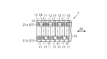
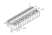
- FIG. 1 is a perspective view of the power supply device.
- FIG. 2 is a diagram illustrating a connection mode of battery cells.
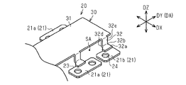
- FIG. 3 is a perspective view showing a part of the battery wiring module.
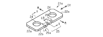
- FIG. 4A is a perspective view of a connecting bus bar.
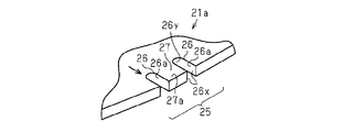
- FIG. 4B is a partial perspective view of the deformed connection bus bar.
- FIG. 5 is a plan view of an extension portion of the flexible wiring board.
- FIG. 6A is a perspective view of a solder connection portion.
- FIG. 6B is a bottom view of the solder connection portion.
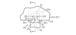
- 6C is a cross-sectional view taken along line BB in FIG. 6B.
- 6D is a cross-sectional view taken along line AA in FIG. 6A.
- FIG. 7 is a partial perspective view showing a state of deformation of the battery wiring module having the comparative structure.
- FIG. 8 is a partial perspective view showing a state of deformation of the battery wiring module according to the embodiment of the present invention.
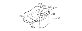
- FIG. 9 is a perspective view of another example of the connection portion in the bus bar.
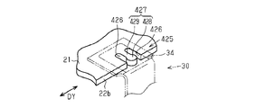
- FIG. 10 is a perspective view of another example of the connection portion in the bus bar.
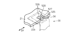
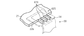
- FIG. 11 is a perspective view of another example of the connection portion in the bus bar.
- FIG. 12 is a perspective view of another example of the connection portion in the bus bar.
- FIG. 13 is a perspective view of another example of the connection portion in the bus bar.
- FIG. 14 is a perspective view of another example of the connection portion in the bus bar.
- FIG. 15 is a perspective view of another example of the power supply device.
- FIG. 16 is a perspective view of another example of the power supply device.
- An object of the present invention is to provide a battery wiring module in which stress is hardly applied to a solder connection portion and is not easily broken even if stress is applied, and a power supply device including the battery wiring module.
- a battery wiring module includes a flexible bus having a plurality of bus bars for connecting a plurality of battery cells in a battery block in series and a plurality of wirings connected to each of the plurality of bus bars.
- a wiring board, and the flexible wiring board includes a main body part and a plurality of extension parts extending from the main body part toward each of the plurality of bus bars, and each of the plurality of extension parts includes the plurality of the plurality of extension parts.
- each of the plurality of extensions has an end, and a pad that is a part of each wiring is disposed at the end, and each of the plurality of bus bars is At least one notch, and the pad is disposed on each bus bar so as to overlap at least a part of the at least one notch, the pad and the at least one notch At least a portion of the are connected by soldering.
- the solder connection portion since the extension portion extending from the main body portion of the flexible wiring board toward the bus bar is connected to the bus bar, even when the battery cell expands or contracts due to vibration, movement, or temperature fluctuation, the solder connection portion It becomes difficult to apply stress. Also, the solder connecting the wiring pad and the bus bar forms a fillet along the notch provided in the bus bar. For this reason, the length of the fillet formed along the side surface of the bus bar is increased compared to the solder connection structure in which the bus bar without the notch and the wiring pad are connected by solder. The connection strength of the solder connection portion becomes high and breakage due to cracks during long-term use hardly occurs. That is, such a solder connection structure is hardly broken even when stress is applied.
- the plurality of bus bars are arranged in a step different from the main body portion of the flexible wiring board, and the pad is formed on the main body portion of the flexible wiring board in each of the plurality of bus bars. Connected to the facing surface.
- the extension of the flexible wiring board and the edge of the bus bar can come into contact with each other.
- the edge of the bus bar rubs against the extended portion of the flexible wiring board, so that the extended portion may be cut.
- the extension part of a flexible wiring board and the edge of a bus bar cannot contact, it becomes difficult to produce wear deterioration that an extension part cuts off due to friction.
- the pad is positioned with respect to each of the plurality of bus bars such that a part of the pad protrudes from an end edge of each of the plurality of bus bars.
- each of the plurality of bus bars has a plurality of the notches.
- a convex portion is formed between the two notches.
- Such a protrusion has the following effects.
- stress due to a change in the relative position of the bus bar is hardly applied to at least the convex portion. This prevents the bus bar and the pad from peeling off.
- each of the plurality of bus bars has a convex portion sandwiched between two notches, the convex portion has a base portion and a distal end portion, and the width of the distal end portion is It is larger than the width of the base. According to this structure, since the length of the fillet formed along the side surface of the bus bar is further increased, the connection strength of the solder connection portion is further increased.
- the at least one notch includes a first part on an edge side of each bus bar, and a second part located closer to the center of the bus bar than the first part, The two parts have a larger width than the first part.
- a battery wiring module includes a plurality of bus bars for connecting a plurality of battery cells in a battery block in series, and a plurality of wirings connected to each of the plurality of bus bars.
- a flexible wiring board having a main body part and a plurality of extensions extending from the main body part toward each of the plurality of bus bars, each of the plurality of extension parts being the plurality of the plurality of extension parts.
- Each of the plurality of extension portions has an end portion, and a pad which is a part of each wiring is disposed at the end portion, and each of the plurality of bus bars is supported.
- the extension portion extending from the main body portion of the flexible wiring board toward the bus bar is connected to the bus bar, even when the battery cell expands / contracts due to vibration, movement, or temperature fluctuation, stress is applied to the solder connection portion. It becomes difficult to join.
- the solder connecting the wiring pad and the bus bar forms a fillet along the protruding portion provided on the bus bar. For this reason, since the length of the fillet formed along the side surface of the bus bar is increased as compared with the solder connection structure in which the bus bar without the protrusion and the wiring pad are connected by solder, the bus bar and the wiring pad The connection strength of the solder connection portion becomes high and breakage due to cracks during long-term use hardly occurs. That is, such a solder connection structure is hardly broken even when stress is applied.
- the plurality of protruding portions have a base portion and a tip portion, and a width of the tip portion is larger than a width of the base portion. According to this structure, since the length of the fillet formed along the side surface of the bus bar is further increased, the connection strength of the solder connection portion is further increased.
- a battery wiring module includes a plurality of bus bars for connecting a plurality of battery cells in a battery block in series, and a plurality of wirings connected to each of the plurality of bus bars.
- a flexible wiring board having a main body part and a plurality of extensions extending from the main body part toward each of the plurality of bus bars, wherein the plurality of bus bars include the flexible wiring board.
- the plate is arranged in a different manner from the main body, each of the plurality of extensions supports one of the plurality of wires, and each of the plurality of extensions has an end.
- a pad that is a part of each wiring is disposed at the end, and each of the plurality of bus bars has a plurality of notches or a plurality of protrusions, and the pad includes the plurality of notches or in front It is arranged on the surface facing the main body portion of the flexible wiring board in each bus bar so as to overlap the whole of the plurality of protruding portions and so that a part of the pad protrudes from each edge of the plurality of bus bars.
- the pad and the bus bar are made of solder disposed at least in the plurality of notches or on the outer periphery of the plurality of protrusions and on a part of the pad protruding from the edge of the bus bar. It is connected.
- a power supply device includes the battery wiring module and a plurality of battery cells connected by the battery wiring module. According to this configuration, it is difficult for stress to be applied to the solder connection portion, and even if stress is applied, the solder connection portion is not easily broken. In addition, since the plurality of wires connected to the bus bar are provided on the flexible wiring board, it is not necessary to connect the wires to the bus bar individually. This simplifies the assembly of the power supply device.
- the power supply device 1 includes a plurality of battery cells 10 and a battery wiring module 20 that connects the battery cells 10.
- the battery cell 10 is comprised by a secondary battery.
- a secondary battery for example, a lithium ion secondary battery, a lithium ion polymer secondary battery, a nickel / cadmium battery, a nickel hydrogen battery, a lead battery, or the like is used.
- the battery cell 10 has a positive electrode terminal 11 and a negative electrode terminal 12. As shown in FIG. 2, the plurality of battery cells 10 are arranged such that the positive electrode terminals 11 and the negative electrode terminals 12 are alternately arranged in the arrangement direction DA of the battery cells 10 (see FIG. 2).
- the plurality of battery cells 10 are electrically connected in series via the bus bar 21 (see the two-dot chain line in FIG. 2).
- the set of the plurality of battery cells 10 is referred to as “battery block 2”.
- the battery wiring module 20 includes the plurality of bus bars 21 and the flexible wiring board 30 described above.
- the main body portion 31 and the bus bar 21 of the flexible wiring board 30 are arranged stepwise in the vertical direction DZ.
- the downward direction in the battery wiring module 20 indicates a direction toward the bottom surface of the battery block 2.
- the vertical direction DY indicates the same direction as the arrangement direction DA of the battery cells 10.
- the horizontal direction DX indicates a direction perpendicular to the height direction (that is, the vertical direction DZ) and the vertical direction DY.
- the battery wiring module 20 is placed on the battery cell 10.
- the bus bar 21 is fastened to both the positive electrode terminal 11 and the negative electrode terminal 12 of two adjacent battery cells 10 or one of the positive electrode terminal 11 and the negative electrode terminal 12 of one battery cell 10 (see later).
- the main body 31 of the flexible wiring board 30 is disposed at a position higher than the bus bar 21 with respect to the upper surface 2 a of the battery block 2.
- a space SA is provided between the flexible wiring board 30 and the battery block 2. This is a space for providing a duct for receiving the electrolytic solution ejected from the electrolytic solution discharge valve when the pressure in the cell increases due to the temperature rise of the battery cell or the like.
- the bus bar 21 will be described with reference to FIGS. 4A and 4B.
- the bus bar 21 can be formed by pressing a metal plate.
- the metal plate for example, pure copper, tough pitch copper, and various alloys are used.
- tin plating is applied to the bus bar 21.
- a connecting bus bar 21 a and a power supply end bus bar 21 b are used as the bus bar 21.
- the power supply end bus bar 21b is attached to each of the battery cells 10 arranged at both ends of the battery block 2 (see FIG. 1).
- the power supply end bus bar 21 b is provided with an insertion hole 24 through which the positive electrode terminal 11 or the negative electrode terminal 12 is inserted.
- FIG. 4A is a perspective view of the connecting bus bar 21a.
- the connecting bus bar 21a connects the two battery cells 10 (see FIG. 1).
- the connection bus bar 21a is provided with two insertion holes 24 through which the positive electrode terminal 11 or the negative electrode terminal 12 is inserted.
- the connecting bus bar 21a is substantially rectangular in plan view. The corners of the connecting bus bar 21a are chamfered.
- a surface perpendicular to the longitudinal direction DY of the connecting bus bar 21a is referred to as a lateral side surface 22a, and a surface along the longitudinal direction DY is referred to as a longitudinal side surface 22b.
- the connecting bus bar 21a is attached to the two battery cells 10
- the side disposed on the center side of the battery cell 10 is referred to as the inside of the connecting bus bar 21a
- the opposite side is referred to as the connecting bus bar 21a. Called outside.
- the two insertion holes 24 are arranged in the longitudinal direction DY.
- One insertion hole 24 is on the side of one lateral side 22a of the connecting bus bar 21a, and the other insertion hole 24 is on the other side side 22a of the connecting bus bar 21a. Close to the side.
- a connecting portion 25 to which the wiring 33 of the flexible wiring board 30 is connected is provided at an intermediate portion (for example, a portion at an equal distance from the two lateral side surfaces 22a) on the vertical side surface 22b inside the connecting bus bar 21a. .
- the connection part 25 has at least one notch part 26 formed by notching a part of the connecting bus bar 21a.
- the notch 26 has an inner surface 26a (see FIG. 4B) that connects the front surface and the back surface of the connecting bus bar 21a. It is preferable that the notch part 26 is comprised so that there may be no corner
- the inner surface 26a of the notch 26 can be configured by a pair of opposed inner side surfaces 26x and a curved surface 26y that connects the pair of inner side surfaces 26x.
- the connecting portion 25 preferably has two or more cutout portions 26.
- interposed between the two notch parts 26 is formed.
- the connecting bus bar 21a is twisted or curved due to vibration, movement or expansion / contraction caused by temperature fluctuation of the two battery cells 10 connected by the connecting bus bar 21a.
- stress concentrates on the outer front end portion (the portion indicated by the arrow in FIG. 4B) of the notch 26, so that stress is suppressed from being applied to the convex portion 27.
- the relative positions of the connecting bus bar 21a and the flexible wiring board 30 change due to expansion and contraction due to vibration, movement, or temperature fluctuation of the battery cell 10.
- the stress that tries to peel off the end portion 32a of the extension portion 32 of the flexible wiring board 30 from the connecting bus bar 21a is applied to the outer end portion of the notch portion 26 (FIG. 4B). (Part indicated by an arrow in FIG. 1), that is, concentrates on a part of the convex part 27 opposite to the tip part 27a. Thereby, it is suppressed that stress (stress which peels the edge part 32a) is added to the convex part 27.
- stress stress which peels the edge part 32a
- the length LA of the convex portion 27 is preferably 0.5 mm or more and 8.0 mm or less.
- the length LA of the convex portion 27 is 0.5 mm or more, the effect of increasing the fillet length described later is increased.
- the length LA of the convex portion 27 is longer than 8.0 mm, that is, when the length of the cutout portion 26 is longer than 8.0 mm, the cross-sectional area of the connecting bus bar 21a (along line XX in FIG. 4A). (Cross-sectional area of the cross section) becomes smaller.
- the width of the connecting bus bar 21a (distance between the two vertical side surfaces 22b) is 20 mm, the thickness of the connecting bus bar 21a is 0.4 mm, and the length LA of the convex portion 27 is less than 8.0 mm. If it is long, the cross-sectional area of the connecting bus bar 21a (the cross-sectional area along the line XX in FIG. 4A) becomes smaller than the specified area, and the resistance between the positive electrode terminal 11 and the negative electrode terminal 12 becomes high. As a result, the connecting bus bar 21a may become hot.
- the width LB of the convex portion 27 is preferably 0.2 mm or greater and 5.0 mm or less.
- the width LB of the convex portion 27 is 0.2 mm or more, the contact area between the convex portion 27 and the pad 34 is sufficient to obtain a suitable shear strength.
- the width LB of the convex portion 27 is shorter than 0.2 mm, even if the length LA of the convex portion 27 is 8.0 mm, the contact area with the pad 34 becomes smaller than the specified area, and the battery cell 10 The measurement error of the voltage between terminals may increase.
- the prescribed area is an area set from the maximum allowable value of the contact resistance between the pad 34 and the convex portion 27.
- the width LB of the convex portion 27 is longer than 5.0 mm, the number of the cutout portions 26 is limited in the connection portion 25 having a predetermined area provided on the connecting bus bar 21a.
- the contact area between the convex portion 27 and the pad 34 is a void that can reduce the strength of the solder connection portion 40 between the pad 34 and the convex portion 27. It is suitable for suppressing the occurrence.
- the power supply end bus bar 21b has a connecting portion 25 having the same structure as that provided in the connecting bus bar 21a.
- the connection portion 25 of the power supply end bus bar 21b is provided with a notch portion 26 similar to that described above.
- the connection bus bar 21a and the power supply end bus bar 21b are described without distinction, they are collectively referred to as the bus bar 21.
- the flexible wiring board 30 will be described with reference to FIG. A two-dot chain line indicated by reference numeral 21a (21) in FIG.
- the flexible wiring board 30 includes a wiring 33 connected to the bus bar 21, a base material 30a that supports the wiring 33, and a cover lay 30b that covers the wiring 33 (see FIG. 6C).
- the substrate 30a and the coverlay 30b are made of polyimide resin, liquid crystal polymer, polyester resin, polyvinyl chloride resin, acrylic resin, vinyl acetate resin, amide resin, polyphenylene sulfide, polyether ether ketone, polyethylene terephthalate (PET). ) Or the like.
- the base material 30a and the coverlay 30b may be formed from the same material, or may be formed from different materials.
- the flexible wiring board 30 is provided with a number of wirings 33 corresponding to the number of bus bars 21.
- a pad 34 that is solder-connected to the bus bar 21 is provided at one end of the wiring 33.
- the pad 34 is disposed on the end portion 32a of the extension portion 32 as will be described later.
- the other end of the wiring 33 (the end opposite to the end connected to the bus bar 21) is connected to the connector 50 (see FIG. 1).
- the connector 50 is connected to the battery cell state detection circuit.
- the battery cell state detection circuit measures the inter-terminal voltage between the positive terminal 11 and the negative terminal 12 of the battery cell 10.
- the battery cell state detection circuit or a control device provided outside the battery cell state detection circuit determines, for example, the state of the battery cell 10 (for example, the state of charge) based on the measured inter-terminal voltage.
- the flexible wiring board 30 includes a main body 31 and an extension 32 extending from the main body 31 toward the bus bar 21.
- the flexible wiring board 30 has at least the same number of extensions 32 as the bus bars 21.
- Each extension portion 32 supports one wire 33, and a pad 34 of the wire 33 is disposed on the back surface of the end portion 32 a of the extension portion 32.
- the base part of the extension part 32 (part connected to the main body part 31) is bent so that the extension part 32 faces the bus bar 21 (see FIG. 3).
- a portion between the body portion 32e and the end portion 32a of the extension portion 32 (hereinafter referred to as “bend portion 32d”) is bent so that the end portion 32a faces outward (see FIG. 3).
- the end portion 32a is wider than the body portion 32e. That is, the width in the longitudinal direction DY at the end portion 32 a is larger than the width in the longitudinal direction DY of the body portion 32 e of the extension portion 32.
- the width of the root portion 32b of the end portion 32a gradually increases toward the tip.
- the edge 32c of the root portion 32b is configured as a concave curve (for example, an arc, a quadratic curve, an exponential curve, etc.).
- solder connection portion 40 the structure of the portion where the pad 34 of the flexible wiring board 30 and the connection portion 25 of the bus bar 21 are connected by the solder 41 (hereinafter referred to as “solder connection portion 40”) will be described.
- FIG. 6A is a perspective view of the solder connection portion 40 as viewed from below.
- FIG. 6B is a bottom view of the solder connection portion 40.
- 6C is a cross-sectional view taken along the line BB of FIG. 6B.
- 6D is a cross-sectional view taken along line AA in FIG. 6A.
- solder 41 As shown in FIGS. 6A and 6B, the bus bar 21 and the pad 34 of the wiring 33 are connected by solder 41.
- solder 41 the kind of solder 41 is not limited, the thing corresponding to reflow is preferable.
- Sn—Cu—Ag, Sn—Ag, Sn—Cu, Sn—Bi, Sn—Bi—In, Sn—Ag—Bi—In, and Sn—Pb solder can be used. .
- the pad 34 is connected to the upper surface 25a of the connection portion 25 (the surface of the connection portion 25 facing the main body portion 31 of the flexible wiring board 30) via the solder 41.
- the pad 34 is disposed so as to overlap at least a part of the notch 26.
- the pad 34 is sized to cover the entire cutout portion 26.
- the end portion 32 a of the extension portion 32 of the flexible wiring board 30 is connected to the connection portion 25 so that the pad 34 overlaps the entire cutout portion 26. More preferably, the end portion 32 a of the extension portion 32 of the flexible wiring board 30 is connected to the connection portion 25 so that a part of the pad 34 protrudes from the end edge (vertical side surface 22 b) of the bus bar 21.
- the fillet 42 of the solder 41 is formed on the entire inner surface 26a of the notch 26 and the vertical side surface 22b of the bus bar 21 by solder connection.
- the fillet 42 formed continuously on the inner surface 26 a of the notch portion 26 and the vertical side surface 22 b of the bus bar 21 increases the strength of the solder connection portion 40.
- the fillet 42 is formed only on the vertical side surface 22b of the bus bar 21.
- the fillet 42 is also formed on the inner surface 26 a of the notch 26. For this reason, the length of the fillet 42 formed along the side surface of the bus bar 21 (including the inner surface 26a and the vertical side surface 22b of the notch 26) is longer than that when the bus bar 21 does not have the notch 26. .
- the root portion 32 b of the extension portion 32 (that is, the portion where the edge 32 c is curved) is disposed inward from the end edge 23 of the bus bar 21.
- the edge 32c of the bent portion 32d extends linearly from the end portion 32a as shown by a two-dot chain line in FIG. 5, the battery cell 10 is twisted by the extension portion 32 due to vibration, movement, or expansion / contraction due to temperature fluctuation.
- the edge 32c of the bent portion 32d is a curve (see FIG. 6A)
- the stress applied to the bent portion 32d is dispersed, and the stress concentration on the bent portion 32d is relaxed. As a result, the occurrence of cracks and tears in the bent portion 32d of the extension portion 32 is suppressed.
- the battery cell 10 may vibrate, move, or expand / contract due to temperature fluctuations.
- the battery cell 10 vibrates or moves.
- the battery cell 10 vibrates or moves.
- the battery cell 10 also moves by expanding and contracting due to ambient temperature fluctuations and the like. In particular, the positional deviation of the battery cell 10 arranged at the end of the power supply device 1 tends to be large.
- the battery wiring module 20 and the battery cell 10 move relative to each other, so that a force is applied to the solder connection portion 40 between the battery wiring module 20 and the battery cell 10.
- the flexible wiring board 30 is pulled or loosened. A state when the two battery cells 10 are moved away from each other will be described while comparing the battery wiring module 120 having a comparative structure and the battery wiring module 20 of the present embodiment.
- the bus bar 121 has the extension 122, and the end 122 a of the extension 122 is connected to the flexible wiring board 30.
- the two connection portions 131 portions where the end portions 122 a of the extension portions 122 are connected
- the flexible wiring board is pulled. Stress is applied to the solder connection portion 140 between the connection portion 131 of 130 and the end portion 122 a of the extension portion 122 of the bus bar 121. If such stress is frequently applied to the solder connection portion 140, the solder connection portion 140 may crack.
- the extension part 32 extends from the main body part 31 of the flexible wiring board 30 as described above, and the end part 32 a of the extension part 32 is connected to the bus bar 21. Yes.
- the end portions 32a of the two extension portions 32 are separated from each other.
- the two extension portions 32 are bent with the base portion (the portion where the extension portion 32 is connected to the main body portion 31) as a fulcrum, or each of the two extension portions 32 bends. It is suppressed that force acts directly on the solder connection portion 40 between the provided pad 34 and the connection portion 25 of the bus bar 21.
- the extension portion 32 may be provided with a folded portion having a bellows shape (including one having a single fold). With this configuration, the force acting on the solder connection portion 40 between the pad 34 and the connection portion 25 of the bus bar 21 can be reduced.
- connection portion 25 of the bus bar 21 is provided with the notch 26, and the fillet 42 of the solder 41 is formed on the inner surface 26 a of the notch 26. Since the pad 34 is disposed so as to protrude from the end edge 23 of the bus bar 21, the fillet 42 of the solder 41 is also formed on the vertical side surface 22 b of the bus bar 21. In addition, a solder layer exists on the upper surface 25a of the bus bar 21. Thus, the solder 41 is in contact with the upper surface 25a of the bus bar 21, the vertical side surface 22b, and the inner surface 26a of the notch 26. Each surface to which the solder 41 is attached extends in different directions.
- the solder connection portion 40 has a structure in which peeling and cracking are unlikely to occur even when the battery cell 10 is vibrated in any of the vertical direction DZ, the horizontal direction DX, and the vertical direction DY. With such a structure, peeling and cracking at the solder connection portion 40 are suppressed.
- the battery wiring module 20 includes a plurality of bus bars 21 and a flexible wiring board 30 having a plurality of wirings 33 connected to each of the plurality of bus bars 21.
- the flexible wiring board 30 includes a main body portion 31 and a plurality of extension portions 32 extending from the main body portion 31 toward each of the plurality of bus bars 21, and the end portions 32 a of the plurality of extension portions 32 are connected to the wiring 33.
- a pad 34 as a part is arranged.
- Each of the plurality of bus bars 21 has at least one notch 26, and the pad 34 is disposed on the bus bar 21 so as to overlap at least a part of the notch 26.
- the pad 34 and at least a part of the notch 26 are connected by solder 41.
- the solder 41 connecting the pad 34 of the wiring 33 and the bus bar 21 forms a fillet 42 along the notch 26 provided in the bus bar 21.
- the length of the fillet 42 formed along the side surface of the bus bar 21 is increased as compared with the solder connection structure in which the bus bar 21 without the notch 26 and the pad 34 of the wiring 33 are connected by the solder 41. Therefore, the connection strength of the solder connection portion 40 between the bus bar 21 and the pad 34 of the wiring 33 is increased (this is referred to as “fillet length increasing effect”), and breakage due to cracks during long-term use is less likely to occur. That is, such a solder connection structure is hardly broken even when stress is applied.
- the plurality of bus bars 21 are arranged differently from the main body 31 of the flexible wiring board 30.
- the pad 34 is connected to the upper surface 25a of the bus bar 21 (the surface facing the main body portion 31 of the flexible wiring board 30).
- the extension 32 of the flexible wiring board 30 and the bus bar 21 can come into contact with each other.
- the edge 28 of the bus bar 21 rubs against the extension portion 32 of the flexible wiring board 30, and thus the extension portion 32 may be cut.
- the flexible wiring board 30 and the battery cell 10 are separated in the vertical direction DZ due to the vibration of the battery cell 10, the extension portion 32 is pulled, and the edge 28 of the bus bar 21 becomes the extension portion 32 of the flexible wiring board 30. It can be rubbed. For this reason, a possibility that the extension part 32 may be cut increases.
- the extension portion 32 of the flexible wiring board 30 and the end edge 28 of the bus bar 21 cannot come into contact with each other, so that wear deterioration such that the extension portion 32 is cut due to rubbing is less likely to occur. .
- the pad 34 is positioned with respect to the bus bar 21 so that a part of the pad 34 protrudes from the end edge 23 of the bus bar 21. According to this configuration, the fillet 42 is easily formed on the side surface of the bus bar 21. Thereby, the connection strength of the solder connection part 40 between the bus bar 21 and the pad 34 of the wiring 33 is further increased.
- the bus bar 21 has a plurality of notches 26. According to this configuration, the convex portion 27 is formed between the two cutout portions 26. Such a convex part 27 brings about the following effects.
- stress concentrates on the notch 26 and the stress applied to the convex 27 is suppressed. That is, according to the above configuration, in the solder connection portion 40 between the bus bar 21 and the pad 34, stress due to the deformation of the bus bar 21 is hardly applied to at least the convex portion 27. 21 and the pad 34 are prevented from peeling off.
- the solder connection portion 40 is subjected to a stress that tries to peel off the end portion 32a of the extension portion 32 of the flexible wiring board 30 from the connecting bus bar 21a, and the outer tip portion of the notch portion 26 (the portion indicated by the arrow in FIG. 4B). ) That is, since it concentrates on the site
- the notch 26 has an inner surface 26a (see FIG. 4B) that connects the front surface (upper surface) and the rear surface (surface facing the battery block 2) of the bus bar 21. If only the purpose of increasing the contact area of the solder 41 in the connection portion 25 of the bus bar 21 is achieved, this purpose is achieved by providing the connection portion 25 with a groove. However, in the case of a simple groove, in the manufacturing process of the battery wiring module 20, it cannot be determined from the outside whether or not the solder 41 is filled in the groove. On the other hand, according to the said structure, the fillet 42 formed in the inner surface 26a of the notch part 26 can be confirmed.
- the pad 34 of the flexible wiring board 30 when the pad 34 of the flexible wiring board 30 is soldered to the connection part 25 of the bus bar 21, the pad 34 can be visually recognized through the notch part 26 with a microscope. For this reason, solder connection defects can be reduced.
- the battery wiring module 20 includes the flexible wiring board 30 and the plurality of bus bars 21, the flexible wiring board 30 and the plurality of bus bars 21 can be solder-connected by reflow. For this reason, compared with the conventional battery wiring module in which the electric wire is wired to each bus bar 21, manufacture is simple.
- various electronic components can be arranged on the flexible wiring board 30.
- a function different from the signal transmission function for transmitting a voltage signal can be added to the battery wiring module 20.
- a temperature sensor can be attached to the flexible wiring board 30. According to such a configuration, it is possible to measure the temperature of the storage chamber in which the power supply device 1 is stored.
- the power supply device 1 includes the battery wiring module 20 and a plurality of battery cells 10 connected by the battery wiring module 20. According to this configuration, it is difficult to apply stress to the solder connection portion 40. For this reason, generation
- the bus bar 21 is formed by stamping from a tin-plated copper alloy material having a thickness of 0.4 mm with a press.
- the bus bar 21 is a rectangle of 30 mm ⁇ 20 mm, and has two insertion holes 24 having a diameter of 8 mm.
- Two notches 26 are provided at equal distances from the two insertion holes 24.
- the pitch of the two notches 26 is 1.6 mm
- the width of the notches 26 is 0.8 mm
- the width LB of the projection 27 between the two notches 26 is 0.8 mm
- the length LA of the (convex portion 27) is 2 mm.
- the pad 34 of the flexible wiring board 30 is configured in a square of 4.5 mm ⁇ 4.5 mm.
- a 0.1 mm thick metal mask is used, and a solder paste with a composition ratio of Ag of 3.0 mass%, copper of 0.5 mass%, and the rest of Sn is printed.
- the pad 34 of the flexible wiring board 30 is arranged on the bus bar 21 as follows.
- the extension portion 32 of the flexible wiring board 30 is arranged so that the pad 34 of the flexible wiring board 30 protrudes from the end edge 23 of the bus bar 21 by 1 mm and the entire cutout portion 26 of the bus bar 21 is disposed on the pad 34.
- the end portion 32a and the plurality of bus bars 21 are positioned.
- the flexible wiring board 30 and the bus bar 21 assembled in this way are put into a reflow furnace. Solder connection is performed in a reflow furnace under a temperature condition where the temperature of the bus bar 21 is 240 ° C. or lower.
- the battery wiring module 20 is obtained.
- a fillet 42 of solder 41 is formed on the inner surface 26 a of the notch portion 26 and the vertical side surface 22 b of the bus bar 21.
- the extension 32 of the flexible wiring board 30 was not cracked or split. This is because the battery wiring module 20 is configured so that the extension portion 32 of the flexible wiring board 30 and the edge 23 of the bus bar 21 do not rub.
- FIGS. 9 to FIG. 14 are perspective views of the bus bars 21 of different embodiments as viewed from below.
- the same components as those in the first embodiment are denoted by the same reference numerals as those in the first embodiment.
- the notch 226 becomes narrower as the distance from the vertical side surface 22b increases. Even with such a configuration, an effect similar to that of the connecting portion shown in the first embodiment can be obtained.
- connection part 325 shown in FIG. 10 has at least two notch parts 326.
- the convex portion 327 sandwiched between the two notches 326 has a base portion 329 having a width (length along the longitudinal direction DY) of the distal end portion 328 (the end portion on the vertical side surface 22b side). Greater than the width of Specifically, the tip portion 328 is an ellipse in plan view, and the longitudinal direction of the tip portion 328 intersects with the extending direction of the convex portion 327. According to such a structure, since the circumference of the convex part 327 is longer than the convex part 27 shown in the first embodiment, compared to the connection part 25 shown in the first embodiment.
- the plan view outline of the tip 328 includes at least one arc and the center angle of one arc is greater than 180 degrees, or the sum of the center angles of the two arcs is It is comprised so that it may become larger than 180 degree
- the portion where the stress can be received from the front that is, in the direction of the applied stress. Since the portion including the vertical surface is enlarged, peeling of the solder connection of the connection portion 325 is further suppressed.
- the stress acting when the bus bar 21 and the pad 34 of the flexible wiring board 30 are separated in the lateral direction DX is received by the base side portion 328a of the distal end portion 328, the contact between the inner surface 329a of the base portion 329 and the solder The stress along the surface in the portion is relaxed, and the solder peeling is suppressed.
- this effect is referred to as a solder peeling suppression effect based on the center angle widening structure.
- connection part 425 shown in FIG. 11 is obtained by changing the structure of the tip part 328 of the convex part 327 in the connection part 325 of FIG.
- the connection part 425 has at least two notch parts 426.
- the convex part 427 sandwiched between the two notch parts 426 has a base part 429 and a tip part 428.
- the tip portion 428 of the convex portion 427 has a larger width (length along the longitudinal direction DY) than the base portion 429, and the tip portion 428 is circular in plan view. Also by this, the effect of increasing the fillet length (that is, the effect of improving the connection strength) is further increased similarly to the connection portion 325 shown in FIG. Moreover, since the front-end
- the notch 526 includes a first part 527 on the side of the vertical side surface 22b of the bus bar 21, that is, an edge side, and a second part 528 located on the center side of the bus bar 21 with respect to the first part 527.
- the second part 528 has a larger width (length along the longitudinal direction DY) than the first part 527. According to such a structure, since the peripheral length of the notch 526 is longer than the notch 26 shown in the first embodiment, the connecting portion 25 shown in the first embodiment.
- each second portion 528 includes at least one arc in plan view, and the center angle of one arc is greater than 180 degrees, or the sum of the center angles of the two arcs is It is comprised so that it may become larger than 180 degree
- the connection part 525 produces the effect according to the solder peeling suppression effect based on a center angle expansion structure.
- the structure of the cutout portion 526 of the connection portion 525 can be applied to the cutout portions 326 and 426 of the connection portions 325 and 425 shown in FIG. 10 or FIG.
- the 13 has three protrusions 670 instead of the notch 26 shown in the first embodiment.
- the width of the protrusion 670 is constant in the extending direction of the protrusion 670.
- the pad 34 of the flexible wiring board 30 is disposed so as to overlap at least a part of the protrusion 670.
- the pad 34 is sized to cover the entire three protrusions 670, and is disposed so as to overlap the entire three protrusions 670.
- a fillet is formed around the protrusion 670 by solder connection between the pad 34 of the flexible wiring board 30 and the protrusion 670. That is, the protrusion 670 provides an effect of increasing the fillet length (that is, an effect of increasing the fillet length). Therefore, the connection part 625 has an effect according to the connection part 25 of the first embodiment.
- the protruding portion 770 has a base portion 771 and a tip portion 772, and the width of the tip portion 772 (the length along the longitudinal direction DY) is larger than the width of the base portion 771.
- the connection is more than that of the connection 625 shown in FIG. 13.
- the length of the fillet formed in the portion 725 is increased, and the effect of increasing the fillet length (that is, the effect of improving the connection strength) is further increased.
- each tip 772 includes at least one arc in plan view, and the center angle of one arc is greater than 180 degrees, or the sum of the center angles of the two arcs is 180. Configured to be greater than degrees. For this reason, the connection part 725 produces the effect according to the solder peeling suppression effect based on a center angle expansion structure.
- the main body 31 of the flexible wiring board 30 and the plurality of bus bars 21 may be arranged on the same surface. In that case, by forming a mountain-shaped bent portion in the extension portion 32 extending from the main body portion 31 and solder-connecting the pad 34 of the extension portion 32 to the upper surface of the bus bar 21, the same effect as this embodiment can be obtained. .
- the battery wiring module 20 can include, for example, two flexible wiring boards 30.
- the two flexible wiring boards 30 are arranged so as to correspond to each of the two electrode rows arranged in the vertical direction DY of the battery block 2.
- the battery wiring module 20 includes two flexible wiring boards 30, a printed wiring board 60 that supports the two flexible wiring boards 30 may be provided.
- the printed wiring board 60 and the flexible wiring board 30 are connected via the connector 50 or connected between terminals.
- SYMBOLS 1 Power supply device, 2 ... Battery block, 2a ... Upper surface, 10 ... Battery cell, 11 ... Positive electrode terminal, 12 ... Negative electrode terminal, 20 ... Battery wiring module, 21 ... Bus bar, 21a ... Bus bar for connection, 21b ... Power supply edge part Bus bar, 22a ... lateral side, 22b ... vertical side, 23 ... end edge, 24 ... insertion hole, 25 ... connecting part, 25a ... upper surface, 26 ... notch, 26a ... inner surface, 26x ... inner side, 26y ... curved Surface, 27 ... convex part, 27a ... tip part, 28 ... edge, 30 ... flexible wiring board, 30a ... base material, 30b ...
Landscapes
- Chemical & Material Sciences (AREA)
- Chemical Kinetics & Catalysis (AREA)
- Electrochemistry (AREA)
- General Chemical & Material Sciences (AREA)
- Engineering & Computer Science (AREA)
- Manufacturing & Machinery (AREA)
- Connection Of Batteries Or Terminals (AREA)
- Battery Mounting, Suspending (AREA)
Abstract
Description
本出願は、2015年4月27日出願の日本出願第2015-090728号に基づく優先権を主張し、前記日本出願に記載された全ての記載内容を援用するものである。
特許文献3の電源装置では、半田接続部にクラックが生じるおそれがある。例えば、電源装置が振動、移動または温度変動により膨張・収縮し、複数の電池セルが離間したり接近したりすると、これに伴って複数のバスバーが離間したり接近したり相対的な位置が変化する。そうすると、フレキシブル配線板において2つのバスバー接続部位の間の部分が引っ張られたり、撓んだりして、半田接続部(バスバー接続部位とフレキシブル配線板との接続部)に、応力が断続的に加わるようになる。このような応力が半田接続部に頻繁に加わると、半田接続部にクラックが生じる。
[本開示の効果]
本開示によれば、半田接続部に応力が加わり難く、応力が加わっても破壊され難い電池配線モジュール、及びその電池配線モジュールを備えた電源装置を提供できる。
最初に本願発明の実施形態を列記して説明する。
(1)本発明の一実施形態に係る電池配線モジュールは、電池ブロックの複数の電池セルを直列接続するための複数のバスバーと、前記複数のバスバーの各々に接続された複数の配線を有するフレキシブル配線板とを備え、前記フレキシブル配線板は、本体部と、前記本体部から前記複数のバスバーの各々に向かって延びる複数の延長部とを有し、前記複数の延長部の各々は前記複数の配線のうちの1本を支持し、かつ、前記複数の延長部の各々は端部を有し、前記端部に各配線の一部分であるパッドが配置されており、前記複数のバスバーの各々は少なくとも1つの切欠き部を有し、前記パッドは前記少なくとも1つの切欠き部の少なくとも一部に重なるように、各バスバー上に配置されており、前記パッドと前記少なくとも1つの切欠き部の少なくとも一部とは半田で接続されている。
(4)上記電池配線モジュールにおいて、前記複数のバスバーの各々は複数の前記切欠き部を有する。
(10)電源装置は、上記の電池配線モジュールと、前記電池配線モジュールによって接続された複数の電池セルとを備える。この構成によれば、半田接続部に応力が加わり難く、応力が加わっても半田接続部が破壊され難い。また、バスバーに接続される複数の配線がフレキシブル配線板に設けられているため、配線をバスバーに個々に接続する手間がかからなくなる。これにより、電源装置の組み立てが簡単になる。
本発明の第一実施形態に係る電池配線モジュール及びそれを備える電源装置について、図面を参照しつつ以下に説明する。なお、本発明は、これらの例示に限定されるものではなく、請求の範囲によって示され、請求の範囲と均等の意味およびこの請求の範囲内での全ての変更が含まれることが意図される。
電源装置1は、複数の電池セル10と、電池セル10を接続する電池配線モジュール20とを備える。電池セル10は、2次電池により構成される。2次電池として、例えば、リチウムイオン2次電池、リチウムイオンポリマー2次電池、ニッケル・カドミウム電池、ニッケル水素電池、鉛電池等が用いられる。電池セル10は、正極端子11と負極端子12とを有する。図2に示されるように、複数の電池セル10は、電池セル10の並び方向DAに正極端子11と負極端子12とが交互に並ぶように配置される(図2参照)。複数の電池セル10は、バスバー21を介して電気的に直列接続される(図2の2点鎖線参照)。以降、複数の電池セル10のセットを「電池ブロック2」という。
バスバー21は、金属板のプレスにより形成され得る。金属板としては、例えば純銅、タフピッチ銅、各種の合金が用いられる。好ましくは、バスバー21には錫めっきが施される。
連結用バスバー21aは、2つの電池セル10を接続する(図1参照)。連結用バスバー21aには、正極端子11または負極端子12が挿通する挿通孔24が2個設けられている。
図4Bに示されるように、連結用バスバー21aにより連結された2個の電池セル10の振動、移動または温度変動による膨張・収縮等に起因して連結用バスバー21aが捩れまたは湾曲する。このとき、切欠き部26の外側先端部(図4Bにおいて矢印で示す部位)に応力が集中するため、凸部27に応力が加わることが抑制される。
フレキシブル配線板30は、バスバー21に接続される配線33と、配線33を支持する基材30aと、配線33を覆うカバーレイ30bとにより構成されている(図6C参照)。
半田41の種類は限定されないが、リフロー対応のものが好ましい。例えば、Sn-Cu-Ag系、Sn-Ag系、Sn-Cu系、Sn-Bi系、Sn-Bi-In系、Sn-Ag-Bi-In系、Sn-Pb系の半田が用いられ得る。
電池セル10は、振動し、移動しまたは温度変動により膨張・収縮することがある。例えば、電源装置1が家庭用の蓄電池に用いられる場合で、車両の交通量が多い場所または鉄道線路に近い場所に蓄電池が設置されるとき、電池セル10が振動しまたはこれにより移動する。電源装置1が車両に搭載されるときは、電池セル10が振動しまたはこれにより移動する。電池セル10は、周囲の温度変動等に起因して膨張・収縮することによっても移動する。特に、電源装置1の端に配置される電池セル10の位置ずれが大きくなり易い。電池セル10が振動し、移動し、または膨張・収縮すると、電池配線モジュール20と電池セル10とが相対移動するため、電池配線モジュール20と電池セル10との半田接続部40に力が加わる。例えば、2つの電池セル10が離間及び接近するように振動すると、フレキシブル配線板30が引っ張られたり弛んだりする。2つの電池セル10が離間するように移動するときの様子を、比較構造の電池配線モジュール120と本実施形態の電池配線モジュール20とを比較しながら説明する。
(1)電池配線モジュール20は、複数のバスバー21と、複数のバスバー21の各々に接続された複数の配線33を有するフレキシブル配線板30とを備える。フレキシブル配線板30は、本体部31と、本体部31から複数のバスバー21の各々に向かって延びる複数の延長部32とを有し、複数の延長部32の端部32aには、配線33の一部分であるパッド34が配置されている。複数のバスバー21の各々は少なくとも1つの切欠き部26を有し、パッド34は切欠き部26の少なくとも一部に重なるように、バスバー21上に配置されている。パッド34と切欠き部26の少なくとも一部とは半田41で接続されている。
この構成によれば、バスバー21の側面にフィレット42が形成され易くなる。これにより、バスバー21と配線33のパッド34との半田接続部40の接続強度が更に高くなる。
この構成によれば、2つの切欠き部26の間に凸部27が形成される。このような凸部27は次の効果をもたらす。電池セル10の振動、移動または温度変動による膨張・収縮によりバスバー21が捩れたり湾曲したりすると、切欠き部26に応力が集中し、凸部27に加わる応力が抑制される。すなわち、上記構成によれば、バスバー21とパッド34との半田接続部40において、少なくとも凸部27にはバスバー21の変形に起因する応力が加わり難くなるため、バスバー21の変形に起因してバスバー21とパッド34とが剥離することが抑制される。
バスバー21の接続部25において半田41が接触する面積を増大させることだけを目的とすれば、接続部25に溝を設けることによりこの目的が達成される。しかし単なる溝である場合、電池配線モジュール20の製造工程において、溝内に半田41が充填されているか否かを外部から判定することができない。これに対し、上記構成によれば、切欠き部26の内面26aに形成されたフィレット42を確認することができる。また、電池配線モジュール20の製造工程において、バスバー21の接続部25にフレキシブル配線板30のパッド34を半田付けするとき、目視でまたは顕微鏡により切欠き部26を通してパッド34を視認可能である。このため、半田接続不良を少なくすることができる。
電池配線モジュール20の製造例を説明する。
バスバー21は、0.4mm厚の錫めっき済銅合金材からプレスで打ち抜いて形成される。例えば、バスバー21は、30mm×20mmの矩形であり、直径8mmの2個の挿通孔24を有する。2つの挿通孔24から等しい距離に、2個の切欠き部26が設けられる。2個の切欠き部26のピッチは1.6mm、切欠き部26の幅は0.8mm、2個の切欠き部26の間の凸部27の幅LBは0.8mm、切欠き部26(凸部27)の長さLAは2mmである。バスバー21を樹脂ケースに収容する場合は、樹脂ケースの突起に係合させるための小切り欠けが4つの角部近傍にそれぞれ形成される。
バスバー21における接続部25の他の実施形態を、図9~14を参照して説明する。図9~図14は、異なる実施形態のバスバー21を下側から見た斜視図である。図9~図14に示されるバスバー21において、第一実施形態と同じ構成要素には同実施形態と同じ符号が付されている。
・電池配線モジュール20を電池ブロック2の上に取り付ける際に、フレキシブル配線板30及びバスバー21を樹脂プロテクタ(樹脂ケース)に収容して、電池ブロック2に取り付けることが好ましい。
Claims (10)
- 電池配線モジュールであって、
電池ブロックの複数の電池セルを直列接続するための複数のバスバーと、
前記複数のバスバーの各々に接続された複数の配線を有するフレキシブル配線板とを備え、
前記フレキシブル配線板は、本体部と、前記本体部から前記複数のバスバーの各々に向かって延びる複数の延長部とを有し、
前記複数の延長部の各々は前記複数の配線のうちの1本を支持し、かつ、前記複数の延長部の各々は端部を有し、前記端部に各配線の一部分であるパッドが配置されており、
前記複数のバスバーの各々は少なくとも1つの切欠き部を有し、前記パッドは前記少なくとも1つの切欠き部の少なくとも一部に重なるように、各バスバー上に配置されており、
前記パッドと前記少なくとも1つの切欠き部の少なくとも一部とは半田で接続されている
電池配線モジュール。 - 前記複数のバスバーは、前記フレキシブル配線板の前記本体部とは段違いに配置され、
前記パッドは、前記複数のバスバーの各々における前記フレキシブル配線板の前記本体部に向く面に接続される
請求項1に記載の電池配線モジュール。 - 前記パッドは、前記パッドの一部が前記複数のバスバーの各々の端縁から出るように、前記複数のバスバーの各々に対して位置決めされている
請求項1または請求項2に記載の電池配線モジュール。 - 前記複数のバスバーの各々は複数の前記切欠き部を有する
請求項1から請求項3のいずれか1項に記載の電池配線モジュール。 - 前記複数のバスバーの各々は2つの前記切欠き部に挟まれた凸部を有し、前記凸部は基部及び先端部を有し、前記先端部の幅は前記基部の幅よりも大きい
請求項4に記載の電池配線モジュール。 - 前記少なくとも1つの切欠き部は、各バスバーの端縁側の第1部位と、第1部位よりも前記バスバーの中心側に位置する第2部位とを含み、第2部位は、第1部位よりも大きい幅を有する
請求項1から請求項5のいずれか1項に記載の電池配線モジュール。 - 電池配線モジュールであって、
電池ブロックの複数の電池セルを直列接続するための複数のバスバーと、
前記複数のバスバーの各々に接続された複数の配線を有するフレキシブル配線板とを備え、
前記フレキシブル配線板は、本体部と、前記本体部から前記複数のバスバーの各々に向かって延びる複数の延長部とを有し、
前記複数の延長部の各々は前記複数の配線のうちの1本を支持し、かつ、前記複数の延長部の各々は端部を有し、前記端部に各配線の一部分であるパッドが配置されており、
前記複数のバスバーの各々は複数の突出部を有し、前記パッドは前記複数の突出部の少なくとも一部に重なるように、各バスバー上に配置されており、
前記パッドと前記複数の突出部の少なくとも一部とは半田で接続されている
電池配線モジュール。 - 前記複数の突出部は基部及び先端部を有し、前記先端部の幅は前記基部の幅よりも大きい
請求項7に記載の電池配線モジュール。 - 電池配線モジュールであって、
電池ブロックの複数の電池セルを直列接続するための複数のバスバーと、
前記複数のバスバーの各々に接続された複数の配線を有するフレキシブル配線板とを備え、
前記フレキシブル配線板は、本体部と、前記本体部から前記複数のバスバーの各々に向かって延びる複数の延長部とを有し、
前記複数のバスバーは、前記フレキシブル配線板の前記本体部とは段違いに配置されており、
前記複数の延長部の各々は前記複数の配線のうちの1本を支持し、かつ、前記複数の延長部の各々は端部を有し、前記端部に各配線の一部分であるパッドが配置されており、
前記複数のバスバーの各々は複数の切欠き部または複数の突出部を有し、前記パッドは、前記複数の切欠き部または前記複数の突出部の全体に重なるように、かつ前記パッドの一部が前記複数のバスバーの各々の端縁から出るように、各バスバーおける前記フレキシブル配線板の前記本体部に向く面上に配置されており、
前記パッドと前記バスバーとは、少なくとも前記複数の切欠き部内または前記複数の突出部の外周と、前記バスバーの端縁から出ている前記パッドの一部上とに配置された半田で接続されている
電池配線モジュール。 - 請求項1から請求項9のいずれか1項に記載の電池配線モジュールと、前記電池配線モジュールによって接続された複数の電池セルとを備える電源装置。
Priority Applications (3)
| Application Number | Priority Date | Filing Date | Title |
|---|---|---|---|
| CN201680023966.4A CN107534121B (zh) | 2015-04-27 | 2016-04-25 | 电池布线模块和设置有电池布线模块的电源装置 |
| US15/565,843 US10297808B2 (en) | 2015-04-27 | 2016-04-25 | Battery wiring module and power supply device provided with battery wiring module |
| JP2017515542A JP6572304B2 (ja) | 2015-04-27 | 2016-04-25 | 電池配線モジュール及びその電池配線モジュールを備えた電源装置 |
Applications Claiming Priority (2)
| Application Number | Priority Date | Filing Date | Title |
|---|---|---|---|
| JP2015-090728 | 2015-04-27 | ||
| JP2015090728 | 2015-04-27 |
Publications (1)
| Publication Number | Publication Date |
|---|---|
| WO2016175180A1 true WO2016175180A1 (ja) | 2016-11-03 |
Family
ID=57199698
Family Applications (1)
| Application Number | Title | Priority Date | Filing Date |
|---|---|---|---|
| PCT/JP2016/062935 Ceased WO2016175180A1 (ja) | 2015-04-27 | 2016-04-25 | 電池配線モジュール及びその電池配線モジュールを備えた電源装置 |
Country Status (4)
| Country | Link |
|---|---|
| US (1) | US10297808B2 (ja) |
| JP (1) | JP6572304B2 (ja) |
| CN (1) | CN107534121B (ja) |
| WO (1) | WO2016175180A1 (ja) |
Cited By (8)
| Publication number | Priority date | Publication date | Assignee | Title |
|---|---|---|---|---|
| CN108206246A (zh) * | 2016-12-19 | 2018-06-26 | 莫仕连接器(成都)有限公司 | 电池连接模块及电池装置 |
| JP2019032931A (ja) * | 2017-08-04 | 2019-02-28 | 矢崎総業株式会社 | 導体モジュール |
| JP2019046791A (ja) * | 2017-09-06 | 2019-03-22 | 寧徳時代新能源科技股▲分▼有限公司Contemporary Amperex Technology Co., Limited | 電池モジュール |
| CN112805872A (zh) * | 2018-10-02 | 2021-05-14 | 株式会社自动网络技术研究所 | 柔性印制电路板、布线部件、蓄电模块以及连接模块 |
| WO2022044645A1 (ja) * | 2020-08-27 | 2022-03-03 | 株式会社オートネットワーク技術研究所 | 車載用配線モジュール |
| CN115051118A (zh) * | 2018-12-29 | 2022-09-13 | 东莞莫仕连接器有限公司 | 电池连接模块 |
| US12283720B2 (en) | 2019-03-12 | 2025-04-22 | Vehicle Energy Japan Inc. | Bus bar, and battery module using same |
| US12308464B2 (en) | 2019-09-03 | 2025-05-20 | Gs Yuasa International Ltd. | Energy storage apparatus |
Families Citing this family (15)
| Publication number | Priority date | Publication date | Assignee | Title |
|---|---|---|---|---|
| CN108206259B (zh) | 2016-12-19 | 2020-10-16 | 莫仕连接器(成都)有限公司 | 液态电池连接模块及电池装置 |
| JP6556175B2 (ja) * | 2017-02-28 | 2019-08-07 | 矢崎総業株式会社 | 導電モジュール、及び、電池パック |
| JP7087348B2 (ja) * | 2017-11-08 | 2022-06-21 | 株式会社オートネットワーク技術研究所 | バスバーモジュール及びバスバー |
| CN108767519B (zh) * | 2018-06-28 | 2024-07-16 | 比亚迪股份有限公司 | 一种动力电池采压fpc组件 |
| EP3595037B1 (en) * | 2018-07-10 | 2023-04-19 | Yazaki Corporation | Structure of connection among circuit body, bus bar and electronic element |
| JP7022345B2 (ja) * | 2018-11-22 | 2022-02-18 | 株式会社オートネットワーク技術研究所 | 接続モジュール |
| CN111599955B (zh) * | 2019-03-22 | 2024-04-30 | 骆驼集团新能源电池有限公司 | 一种无模组类铝壳电池模组及铝壳电池 |
| CN114041236A (zh) * | 2019-04-22 | 2022-02-11 | Cps 科技控股有限公司 | 电池模块和具有应力消除特征的汇流条 |
| JP7403240B2 (ja) | 2019-06-07 | 2023-12-22 | 日本メクトロン株式会社 | 配線材及びバッテリモジュール |
| JP7041098B2 (ja) * | 2019-06-17 | 2022-03-23 | 矢崎総業株式会社 | バスバモジュール |
| JP7025376B2 (ja) | 2019-06-17 | 2022-02-24 | 矢崎総業株式会社 | バスバモジュール |
| KR102849125B1 (ko) * | 2019-12-05 | 2025-08-25 | 삼성에스디아이 주식회사 | 배터리 팩 |
| JP7614174B2 (ja) * | 2020-03-11 | 2025-01-15 | 三洋電機株式会社 | バスバーおよび電池モジュール |
| CN113363675B (zh) * | 2021-07-02 | 2025-07-15 | 深圳市科达利实业股份有限公司 | 一种圆柱电池 |
| WO2026011324A1 (zh) * | 2024-07-09 | 2026-01-15 | 宁德时代新能源科技股份有限公司 | 一种电池装置及用电装置 |
Citations (5)
| Publication number | Priority date | Publication date | Assignee | Title |
|---|---|---|---|---|
| JP2010123299A (ja) * | 2008-11-17 | 2010-06-03 | Toshiba Corp | 二次電池パック |
| WO2010113455A1 (ja) * | 2009-03-31 | 2010-10-07 | 三洋電機株式会社 | 電池モジュール、バッテリシステムおよび電動車両 |
| JP2011228217A (ja) * | 2010-04-22 | 2011-11-10 | Yazaki Corp | 配線材の接続構造 |
| JP2013105571A (ja) * | 2011-11-11 | 2013-05-30 | Auto Network Gijutsu Kenkyusho:Kk | 電池配線モジュール |
| JP2015022965A (ja) * | 2013-07-22 | 2015-02-02 | 株式会社デンソー | 組電池 |
Family Cites Families (2)
| Publication number | Priority date | Publication date | Assignee | Title |
|---|---|---|---|---|
| JP2011049047A (ja) | 2009-08-27 | 2011-03-10 | Autonetworks Technologies Ltd | 電池接続アセンブリ |
| JP5811396B2 (ja) | 2011-08-02 | 2015-11-11 | 株式会社オートネットワーク技術研究所 | 電池配線モジュール |
-
2016
- 2016-04-25 US US15/565,843 patent/US10297808B2/en active Active
- 2016-04-25 WO PCT/JP2016/062935 patent/WO2016175180A1/ja not_active Ceased
- 2016-04-25 JP JP2017515542A patent/JP6572304B2/ja active Active
- 2016-04-25 CN CN201680023966.4A patent/CN107534121B/zh active Active
Patent Citations (5)
| Publication number | Priority date | Publication date | Assignee | Title |
|---|---|---|---|---|
| JP2010123299A (ja) * | 2008-11-17 | 2010-06-03 | Toshiba Corp | 二次電池パック |
| WO2010113455A1 (ja) * | 2009-03-31 | 2010-10-07 | 三洋電機株式会社 | 電池モジュール、バッテリシステムおよび電動車両 |
| JP2011228217A (ja) * | 2010-04-22 | 2011-11-10 | Yazaki Corp | 配線材の接続構造 |
| JP2013105571A (ja) * | 2011-11-11 | 2013-05-30 | Auto Network Gijutsu Kenkyusho:Kk | 電池配線モジュール |
| JP2015022965A (ja) * | 2013-07-22 | 2015-02-02 | 株式会社デンソー | 組電池 |
Cited By (14)
| Publication number | Priority date | Publication date | Assignee | Title |
|---|---|---|---|---|
| JP2018101618A (ja) * | 2016-12-19 | 2018-06-28 | モレックス エルエルシー | バッテリ接続モジュール及びバッテリデバイス |
| CN108206246B (zh) * | 2016-12-19 | 2020-10-16 | 莫仕连接器(成都)有限公司 | 液态电池连接模块及电池装置 |
| CN108206246A (zh) * | 2016-12-19 | 2018-06-26 | 莫仕连接器(成都)有限公司 | 电池连接模块及电池装置 |
| JP2019032931A (ja) * | 2017-08-04 | 2019-02-28 | 矢崎総業株式会社 | 導体モジュール |
| JP2019046791A (ja) * | 2017-09-06 | 2019-03-22 | 寧徳時代新能源科技股▲分▼有限公司Contemporary Amperex Technology Co., Limited | 電池モジュール |
| CN112805872B (zh) * | 2018-10-02 | 2024-01-30 | 株式会社自动网络技术研究所 | 柔性印制电路板、布线部件、蓄电模块以及连接模块 |
| CN112805872A (zh) * | 2018-10-02 | 2021-05-14 | 株式会社自动网络技术研究所 | 柔性印制电路板、布线部件、蓄电模块以及连接模块 |
| CN115051118A (zh) * | 2018-12-29 | 2022-09-13 | 东莞莫仕连接器有限公司 | 电池连接模块 |
| US12283720B2 (en) | 2019-03-12 | 2025-04-22 | Vehicle Energy Japan Inc. | Bus bar, and battery module using same |
| US12308464B2 (en) | 2019-09-03 | 2025-05-20 | Gs Yuasa International Ltd. | Energy storage apparatus |
| WO2022044645A1 (ja) * | 2020-08-27 | 2022-03-03 | 株式会社オートネットワーク技術研究所 | 車載用配線モジュール |
| US12237598B2 (en) | 2020-08-27 | 2025-02-25 | Autonetworks Technologies, Ltd. | In-vehicle wiring module |
| JP7380483B2 (ja) | 2020-08-27 | 2023-11-15 | 株式会社オートネットワーク技術研究所 | 車載用配線モジュール |
| JP2022038763A (ja) * | 2020-08-27 | 2022-03-10 | 株式会社オートネットワーク技術研究所 | 車載用配線モジュール |
Also Published As
| Publication number | Publication date |
|---|---|
| JPWO2016175180A1 (ja) | 2018-02-22 |
| JP6572304B2 (ja) | 2019-09-04 |
| US20180130989A1 (en) | 2018-05-10 |
| US10297808B2 (en) | 2019-05-21 |
| CN107534121A (zh) | 2018-01-02 |
| CN107534121B (zh) | 2020-05-12 |
Similar Documents
| Publication | Publication Date | Title |
|---|---|---|
| JP6572304B2 (ja) | 電池配線モジュール及びその電池配線モジュールを備えた電源装置 | |
| KR101050318B1 (ko) | 이차 전지 모듈 | |
| US8882544B2 (en) | Connector | |
| US9413086B2 (en) | Cost optimized cell voltage tap-off connection | |
| KR20170110746A (ko) | 배터리 모듈 | |
| CN112768976A (zh) | 一种功率模块用引线端子 | |
| CN107210104B (zh) | 安装有外接ptc元件的筒形电池 | |
| JP5819043B2 (ja) | 電気化学セル、及び回路基板 | |
| US9831583B2 (en) | Connector | |
| US8815421B2 (en) | Printed circuit board and battery pack using the same | |
| JP6662103B2 (ja) | 蓄電装置 | |
| US9570827B2 (en) | Contact member | |
| CN118921842B (zh) | 电池装置用线路板组件 | |
| JP5927435B2 (ja) | 電子装置 | |
| JP6022855B2 (ja) | ハウジングレスコネクタ | |
| CN116959884A (zh) | 一种电容元件 | |
| KR101344935B1 (ko) | 컨넥터용 콘택트 | |
| CN111585138B (zh) | 电缆和制造电缆的方法 | |
| KR102594639B1 (ko) | 응력 집중을 방지한 클립 개스킷 | |
| JP2011108551A (ja) | 端子付電池 | |
| KR102427191B1 (ko) | 전지팩 어셈블리 | |
| JP2017084576A (ja) | 導電接続構造 | |
| KR200372025Y1 (ko) | 탄성핀 | |
| JP2001127226A (ja) | 半導体素子 | |
| JP2012049195A (ja) | 半導体装置及びリードフレーム |
Legal Events
| Date | Code | Title | Description |
|---|---|---|---|
| 121 | Ep: the epo has been informed by wipo that ep was designated in this application |
Ref document number: 16786457 Country of ref document: EP Kind code of ref document: A1 |
|
| ENP | Entry into the national phase |
Ref document number: 2017515542 Country of ref document: JP Kind code of ref document: A |
|
| WWE | Wipo information: entry into national phase |
Ref document number: 15565843 Country of ref document: US |
|
| NENP | Non-entry into the national phase |
Ref country code: DE |
|
| 122 | Ep: pct application non-entry in european phase |
Ref document number: 16786457 Country of ref document: EP Kind code of ref document: A1 |