WO2016175061A1 - 希土類磁石の製造方法及び希土類化合物の塗布装置 - Google Patents
希土類磁石の製造方法及び希土類化合物の塗布装置 Download PDFInfo
- Publication number
- WO2016175061A1 WO2016175061A1 PCT/JP2016/062194 JP2016062194W WO2016175061A1 WO 2016175061 A1 WO2016175061 A1 WO 2016175061A1 JP 2016062194 W JP2016062194 W JP 2016062194W WO 2016175061 A1 WO2016175061 A1 WO 2016175061A1
- Authority
- WO
- WIPO (PCT)
- Prior art keywords
- slurry
- sintered magnet
- magnet body
- rare earth
- heating
- Prior art date
Links
Images


Classifications
-
- B—PERFORMING OPERATIONS; TRANSPORTING
- B05—SPRAYING OR ATOMISING IN GENERAL; APPLYING FLUENT MATERIALS TO SURFACES, IN GENERAL
- B05B—SPRAYING APPARATUS; ATOMISING APPARATUS; NOZZLES
- B05B13/00—Machines or plants for applying liquids or other fluent materials to surfaces of objects or other work by spraying, not covered by groups B05B1/00 - B05B11/00
- B05B13/02—Means for supporting work; Arrangement or mounting of spray heads; Adaptation or arrangement of means for feeding work
- B05B13/0221—Means for supporting work; Arrangement or mounting of spray heads; Adaptation or arrangement of means for feeding work characterised by the means for moving or conveying the objects or other work, e.g. conveyor belts
-
- B—PERFORMING OPERATIONS; TRANSPORTING
- B05—SPRAYING OR ATOMISING IN GENERAL; APPLYING FLUENT MATERIALS TO SURFACES, IN GENERAL
- B05D—PROCESSES FOR APPLYING FLUENT MATERIALS TO SURFACES, IN GENERAL
- B05D3/00—Pretreatment of surfaces to which liquids or other fluent materials are to be applied; After-treatment of applied coatings, e.g. intermediate treating of an applied coating preparatory to subsequent applications of liquids or other fluent materials
- B05D3/02—Pretreatment of surfaces to which liquids or other fluent materials are to be applied; After-treatment of applied coatings, e.g. intermediate treating of an applied coating preparatory to subsequent applications of liquids or other fluent materials by baking
-
- B—PERFORMING OPERATIONS; TRANSPORTING
- B22—CASTING; POWDER METALLURGY
- B22F—WORKING METALLIC POWDER; MANUFACTURE OF ARTICLES FROM METALLIC POWDER; MAKING METALLIC POWDER; APPARATUS OR DEVICES SPECIALLY ADAPTED FOR METALLIC POWDER
- B22F3/00—Manufacture of workpieces or articles from metallic powder characterised by the manner of compacting or sintering; Apparatus specially adapted therefor ; Presses and furnaces
- B22F3/24—After-treatment of workpieces or articles
-
- C—CHEMISTRY; METALLURGY
- C22—METALLURGY; FERROUS OR NON-FERROUS ALLOYS; TREATMENT OF ALLOYS OR NON-FERROUS METALS
- C22C—ALLOYS
- C22C38/00—Ferrous alloys, e.g. steel alloys
-
- H—ELECTRICITY
- H01—ELECTRIC ELEMENTS
- H01F—MAGNETS; INDUCTANCES; TRANSFORMERS; SELECTION OF MATERIALS FOR THEIR MAGNETIC PROPERTIES
- H01F1/00—Magnets or magnetic bodies characterised by the magnetic materials therefor; Selection of materials for their magnetic properties
- H01F1/01—Magnets or magnetic bodies characterised by the magnetic materials therefor; Selection of materials for their magnetic properties of inorganic materials
- H01F1/03—Magnets or magnetic bodies characterised by the magnetic materials therefor; Selection of materials for their magnetic properties of inorganic materials characterised by their coercivity
- H01F1/032—Magnets or magnetic bodies characterised by the magnetic materials therefor; Selection of materials for their magnetic properties of inorganic materials characterised by their coercivity of hard-magnetic materials
- H01F1/04—Magnets or magnetic bodies characterised by the magnetic materials therefor; Selection of materials for their magnetic properties of inorganic materials characterised by their coercivity of hard-magnetic materials metals or alloys
- H01F1/047—Alloys characterised by their composition
- H01F1/053—Alloys characterised by their composition containing rare earth metals
- H01F1/0536—Alloys characterised by their composition containing rare earth metals sintered
-
- H—ELECTRICITY
- H01—ELECTRIC ELEMENTS
- H01F—MAGNETS; INDUCTANCES; TRANSFORMERS; SELECTION OF MATERIALS FOR THEIR MAGNETIC PROPERTIES
- H01F1/00—Magnets or magnetic bodies characterised by the magnetic materials therefor; Selection of materials for their magnetic properties
- H01F1/01—Magnets or magnetic bodies characterised by the magnetic materials therefor; Selection of materials for their magnetic properties of inorganic materials
- H01F1/03—Magnets or magnetic bodies characterised by the magnetic materials therefor; Selection of materials for their magnetic properties of inorganic materials characterised by their coercivity
- H01F1/032—Magnets or magnetic bodies characterised by the magnetic materials therefor; Selection of materials for their magnetic properties of inorganic materials characterised by their coercivity of hard-magnetic materials
- H01F1/04—Magnets or magnetic bodies characterised by the magnetic materials therefor; Selection of materials for their magnetic properties of inorganic materials characterised by their coercivity of hard-magnetic materials metals or alloys
- H01F1/047—Alloys characterised by their composition
- H01F1/053—Alloys characterised by their composition containing rare earth metals
- H01F1/055—Alloys characterised by their composition containing rare earth metals and magnetic transition metals, e.g. SmCo5
- H01F1/057—Alloys characterised by their composition containing rare earth metals and magnetic transition metals, e.g. SmCo5 and IIIa elements, e.g. Nd2Fe14B
-
- H—ELECTRICITY
- H01—ELECTRIC ELEMENTS
- H01F—MAGNETS; INDUCTANCES; TRANSFORMERS; SELECTION OF MATERIALS FOR THEIR MAGNETIC PROPERTIES
- H01F1/00—Magnets or magnetic bodies characterised by the magnetic materials therefor; Selection of materials for their magnetic properties
- H01F1/01—Magnets or magnetic bodies characterised by the magnetic materials therefor; Selection of materials for their magnetic properties of inorganic materials
- H01F1/03—Magnets or magnetic bodies characterised by the magnetic materials therefor; Selection of materials for their magnetic properties of inorganic materials characterised by their coercivity
- H01F1/032—Magnets or magnetic bodies characterised by the magnetic materials therefor; Selection of materials for their magnetic properties of inorganic materials characterised by their coercivity of hard-magnetic materials
- H01F1/04—Magnets or magnetic bodies characterised by the magnetic materials therefor; Selection of materials for their magnetic properties of inorganic materials characterised by their coercivity of hard-magnetic materials metals or alloys
- H01F1/06—Magnets or magnetic bodies characterised by the magnetic materials therefor; Selection of materials for their magnetic properties of inorganic materials characterised by their coercivity of hard-magnetic materials metals or alloys in the form of particles, e.g. powder
- H01F1/08—Magnets or magnetic bodies characterised by the magnetic materials therefor; Selection of materials for their magnetic properties of inorganic materials characterised by their coercivity of hard-magnetic materials metals or alloys in the form of particles, e.g. powder pressed, sintered, or bound together
- H01F1/086—Magnets or magnetic bodies characterised by the magnetic materials therefor; Selection of materials for their magnetic properties of inorganic materials characterised by their coercivity of hard-magnetic materials metals or alloys in the form of particles, e.g. powder pressed, sintered, or bound together sintered
-
- H—ELECTRICITY
- H01—ELECTRIC ELEMENTS
- H01F—MAGNETS; INDUCTANCES; TRANSFORMERS; SELECTION OF MATERIALS FOR THEIR MAGNETIC PROPERTIES
- H01F41/00—Apparatus or processes specially adapted for manufacturing or assembling magnets, inductances or transformers; Apparatus or processes specially adapted for manufacturing materials characterised by their magnetic properties
- H01F41/02—Apparatus or processes specially adapted for manufacturing or assembling magnets, inductances or transformers; Apparatus or processes specially adapted for manufacturing materials characterised by their magnetic properties for manufacturing cores, coils, or magnets
- H01F41/0253—Apparatus or processes specially adapted for manufacturing or assembling magnets, inductances or transformers; Apparatus or processes specially adapted for manufacturing materials characterised by their magnetic properties for manufacturing cores, coils, or magnets for manufacturing permanent magnets
- H01F41/0293—Apparatus or processes specially adapted for manufacturing or assembling magnets, inductances or transformers; Apparatus or processes specially adapted for manufacturing materials characterised by their magnetic properties for manufacturing cores, coils, or magnets for manufacturing permanent magnets diffusion of rare earth elements, e.g. Tb, Dy or Ho, into permanent magnets
-
- B—PERFORMING OPERATIONS; TRANSPORTING
- B05—SPRAYING OR ATOMISING IN GENERAL; APPLYING FLUENT MATERIALS TO SURFACES, IN GENERAL
- B05D—PROCESSES FOR APPLYING FLUENT MATERIALS TO SURFACES, IN GENERAL
- B05D1/00—Processes for applying liquids or other fluent materials
- B05D1/02—Processes for applying liquids or other fluent materials performed by spraying
-
- B—PERFORMING OPERATIONS; TRANSPORTING
- B22—CASTING; POWDER METALLURGY
- B22F—WORKING METALLIC POWDER; MANUFACTURE OF ARTICLES FROM METALLIC POWDER; MAKING METALLIC POWDER; APPARATUS OR DEVICES SPECIALLY ADAPTED FOR METALLIC POWDER
- B22F3/00—Manufacture of workpieces or articles from metallic powder characterised by the manner of compacting or sintering; Apparatus specially adapted therefor ; Presses and furnaces
- B22F3/24—After-treatment of workpieces or articles
- B22F2003/248—Thermal after-treatment
-
- H—ELECTRICITY
- H01—ELECTRIC ELEMENTS
- H01F—MAGNETS; INDUCTANCES; TRANSFORMERS; SELECTION OF MATERIALS FOR THEIR MAGNETIC PROPERTIES
- H01F1/00—Magnets or magnetic bodies characterised by the magnetic materials therefor; Selection of materials for their magnetic properties
- H01F1/01—Magnets or magnetic bodies characterised by the magnetic materials therefor; Selection of materials for their magnetic properties of inorganic materials
- H01F1/03—Magnets or magnetic bodies characterised by the magnetic materials therefor; Selection of materials for their magnetic properties of inorganic materials characterised by their coercivity
- H01F1/032—Magnets or magnetic bodies characterised by the magnetic materials therefor; Selection of materials for their magnetic properties of inorganic materials characterised by their coercivity of hard-magnetic materials
- H01F1/04—Magnets or magnetic bodies characterised by the magnetic materials therefor; Selection of materials for their magnetic properties of inorganic materials characterised by their coercivity of hard-magnetic materials metals or alloys
- H01F1/047—Alloys characterised by their composition
- H01F1/053—Alloys characterised by their composition containing rare earth metals
- H01F1/055—Alloys characterised by their composition containing rare earth metals and magnetic transition metals, e.g. SmCo5
- H01F1/057—Alloys characterised by their composition containing rare earth metals and magnetic transition metals, e.g. SmCo5 and IIIa elements, e.g. Nd2Fe14B
- H01F1/0571—Alloys characterised by their composition containing rare earth metals and magnetic transition metals, e.g. SmCo5 and IIIa elements, e.g. Nd2Fe14B in the form of particles, e.g. rapid quenched powders or ribbon flakes
- H01F1/0575—Alloys characterised by their composition containing rare earth metals and magnetic transition metals, e.g. SmCo5 and IIIa elements, e.g. Nd2Fe14B in the form of particles, e.g. rapid quenched powders or ribbon flakes pressed, sintered or bonded together
- H01F1/0577—Alloys characterised by their composition containing rare earth metals and magnetic transition metals, e.g. SmCo5 and IIIa elements, e.g. Nd2Fe14B in the form of particles, e.g. rapid quenched powders or ribbon flakes pressed, sintered or bonded together sintered
Definitions
- the present invention applies a powder containing a rare earth compound to a sintered magnet body and heat-treats it to absorb the rare earth element in the sintered magnet body.
- the present invention relates to a method for producing a rare earth magnet capable of efficiently obtaining a rare earth magnet excellent in magnetic properties by coating, and a rare earth compound coating apparatus preferably used in the method for producing the rare earth magnet.
- Rare earth permanent magnets such as Nd—Fe—B are increasingly used for their excellent magnetic properties.
- a rare earth compound powder is applied to the surface of the sintered magnet body and heat treated, and the rare earth element is absorbed and diffused into the sintered magnet body to obtain a rare earth permanent magnet.
- Patent Document 1 Japanese Patent Laid-Open No. 2007-53351
- Patent Document 2 International Publication No. 2006/043348
- the coercive force is reduced while suppressing a decrease in residual magnetic flux density. It can be increased.
- the rare earth compound is applied by immersing the sintered magnet body in a slurry in which the powder containing the rare earth compound is dispersed in water or an organic solvent, or spraying the slurry onto the sintered magnet body.
- drying methods are common, but in these methods, it is difficult to uniformly apply to the sintered magnet body, and the film thickness of the coating film tends to vary. Furthermore, since the film is not dense, an excessive coating amount is required to increase the coercive force to saturation.
- the present invention has been made in view of the above circumstances, and a sintered magnet body having an R 1 —Fe—B-based composition (R 1 is one or more selected from rare earth elements including Y and Sc) oxide of R 2, fluoride, acid fluoride, one hydroxide or hydride (R 2 is at least one element selected from rare earth elements inclusive of Y and Sc) are selected from or two or more powder containing dispersed slurry is then coated dried solvent, the powder is coated on the sintered magnet body surface, by heat-treating this rare earth permanent magnet is absorbed the R 2 in the sintered magnet body
- Rare earth magnets with excellent magnetic properties that can be applied uniformly and efficiently during manufacturing, and the amount of coating can be controlled to form a dense powder coating with good adhesion A method of producing a rare earth magnet capable of efficiently obtaining And to provide a coating apparatus of the preferred rare-earth compounds used in the method for producing the rare earth magnet.
- the present invention provides the following rare-earth magnet manufacturing methods [1] to [9].
- a sintered magnet body having an R 1 —Fe—B-based composition (R 1 is one or more selected from rare earth elements including Y and Sc), an oxide of R 2 , a fluoride, an acid A slurry in which a powder containing one or more selected from fluoride, hydroxide or hydride (R 2 is one or more selected from rare earth elements including Y and Sc) is dispersed in a solvent.
- the powder is applied to the surface of the sintered magnet body by applying and drying to remove the solvent of the slurry, and the heat treatment is performed to absorb the R 2 in the sintered magnet body.
- a method for producing a rare earth magnet comprising heating or heating the sintered magnet body before applying the slurry.
- the solvent of the slurry is water, and the sintered magnet body is heated or heated to 40 to 80 ° C. and then the slurry is applied.
- [4] The method for producing a rare earth magnet according to any one of [1] to [3], wherein the heating or heating is performed by irradiating the sintered magnet body with infrared rays.
- [5] The method for producing a rare earth magnet according to [4], wherein the infrared ray is a near infrared ray having a wavelength of 0.8 to 5 ⁇ m.
- [6] The method for producing a rare earth magnet according to any one of [1] to [5], wherein the slurry is applied by a roller.
- the present invention provides a coating apparatus for rare earth compounds of [10] to [15] below.
- a square plate-like or square block-like sintered magnet body having a R 1 —Fe—B-based composition (R 1 is one or more selected from rare earth elements including Y and Sc) is added to R 2 oxides, fluorides, acid fluorides, hydroxides or hydrides (R 2 is at least one element selected from rare earth elements inclusive of Y and Sc) containing one or more kinds selected from A slurry in which a powder is dispersed in a solvent is applied and dried, and the powder is applied to the surface of the sintered magnet body, and this is heat-treated to absorb the R 2 in the sintered magnet body to produce a rare earth permanent magnet.
- a rare earth compound coating device for applying the powder to the sintered magnet body
- a transport conveyor for transporting the sintered magnet body
- Slurry application means for applying the slurry to the sintered magnet body on the conveyor
- a pre-heating unit that is provided on the upstream side in the transport direction of the slurry application position by the coating unit, and heats or heats the sintered magnet body on the transport conveyor to a predetermined temperature
- the sintered magnet body is supplied and conveyed from the upstream side of the conveyor, the sintered magnet body is heated or heated to a predetermined temperature by the preheating means, and the sintered magnet body heated or heated to the predetermined temperature is heated.
- the slurry is applied to the magnet body by the slurry applying means, and the sintered magnet body coated with the slurry is heated by the drying means and dried to remove the solvent of the slurry, thereby sintering the powder.
- An apparatus for applying a rare earth compound wherein the apparatus is applied to a surface and the sintered magnet body is recovered from a downstream side of the conveyor.
- the drying means includes an infrared heater that irradiates and heats the sintered magnet body with infrared rays, and an exhaust means that removes the solvent vaporized by the infrared irradiation from the periphery of the sintered magnet body [10]. ] Or the rare earth compound coating device of [11]. [13] The rare earth compound coating apparatus according to [11] or [12], wherein either or both of the preheating unit and the drying unit irradiate near infrared rays having a wavelength of 0.8 to 5 ⁇ m. .
- the manufacturing method and the coating apparatus of the present invention apply a slurry in which a rare earth compound powder is dispersed to a sintered magnet body, and dry the slurry to remove the solvent of the slurry.
- the sintered magnet body is heated or heated to a predetermined temperature before applying the slurry, and the slurry is applied to the heated or heated sintered magnet body and dried to obtain a rare earth compound powder.
- the coating film is formed. In this way, by heating the sintered magnet body before slurry application, drying can be completed in a very short time during heat drying after slurry application. Can be evaporated and dried, so that a uniform coating can be efficiently and reliably formed without causing a slurry sagging or the like.
- the slurry is partially applied only to a necessary portion of the sintered magnet body according to the use form of the magnet, and the necessary.
- the slurry coating is performed as described above. Since the subsequent drying can be completed in a very short time, for example, the dripping of the slurry to the side portion that does not require an increase in coercive force is prevented as much as possible, and the powder containing the rare earth compound is wasted. It is possible to prevent the consumption and increase the coercive force extremely efficiently.
- preheating (heating) before slurry application and heat drying after application are carried out by infrared irradiation, particularly with a short wavelength of 0.8 to 5 ⁇ m.
- preheating (heating) and heat drying can be performed efficiently in a short time, and a uniform coating film with the above powder can be reliably obtained without causing cracks.
- the coating apparatus can be downsized.
- a heater that irradiates near infrared rays with a short wavelength of 0.8 to 5 ⁇ m can start heating effectively in 1 to 2 seconds, and can be heated to 100 ° C. within 10 seconds. It is possible and heating and heating can be completed in a very short time. Furthermore, it can be configured at a lower cost than when induction heating is performed, which is advantageous in terms of power consumption. Accordingly, the powder can be applied by drying the slurry more efficiently at a lower cost.
- the radiant heating by the near infrared irradiation the near infrared rays can be transmitted and absorbed inside the slurry coating and heated or heated, so for example heating / heating by applying hot air from the outside.
- the heater tube that generates near-infrared rays with a short wavelength is relatively small, and the dryer and coating device can be miniaturized, so that rare earth magnets can be efficiently produced with small-scale equipment.
- a slurry in which a rare earth compound powder is dispersed can be applied to a sintered magnet body, and the slurry can be efficiently dried to reliably form a uniform and dense coating film made of rare earth magnet powder. . Accordingly, the coating amount can be controlled accurately, and a uniform and dense rare earth compound powder coating film can be efficiently formed on the surface of the sintered magnet body.
- the compound coating apparatus can be miniaturized.
- the rare earth compound powder can be uniformly and densely applied to the surface of the sintered magnet body in this way, the magnetic characteristics with a well increased coercive force can be obtained. An excellent rare earth magnet can be efficiently produced.
- the method for producing a rare earth magnet of the present invention is applied to a sintered magnet body having an R 1 —Fe—B-based composition
- R 1 is one or more selected from rare earth elements including Y and Sc.
- a slurry in which a powder containing benzene is dispersed in a solvent is applied and dried, and the powder is applied to the surface of the sintered magnet body, and this is heat-treated to absorb the R 2 in the sintered magnet body, thereby causing a rare earth permanent magnet Is to be manufactured.
- R 1 —Fe—B based sintered magnet body one obtained by a known method can be used.
- a mother alloy containing R 1 , Fe, B is roughly pulverized, finely pulverized, according to a conventional method. It can be obtained by molding and sintering.
- R 1 is one or more selected from rare earth elements including Y and Sc, specifically, Y, Sc, La, Ce, Pr, Nd, Sm, Eu, Gd, Tb. , Dy, Ho, Er, Yb and Lu.
- the R 1 —Fe—B based sintered magnet body is formed into a predetermined shape by grinding or the like, if necessary, and the surface thereof has an R 2 oxide, fluoride, oxyfluoride, hydroxide, A powder containing one or more hydrides is applied and heat treated to absorb and diffuse (granular boundary diffusion) into the sintered magnet body to obtain a rare earth magnet.
- R 2 is one or more selected from rare earth elements including Y and Sc, and Y, Sc, La, Ce, Pr, Nd, Sm, Eu are selected in the same manner as R 1. , Gd, Tb, Dy, Ho, Er, Yb and Lu.
- one or a plurality of R 2 contains Dy or Tb in a total of 10 atomic% or more, more preferably 20 atomic% or more, particularly 40 atomic% or more.
- R 2 contains 10 atomic% or more of Dy and / or Tb, and the total concentration of Nd and Pr in R 2 is lower than the total concentration of Nd and Pr in R 1 . More preferred.
- the powder is applied by preparing a slurry in which the powder is dispersed in a solvent, applying the slurry to the surface of the sintered magnet body, and drying the slurry.
- the particle size of the powder is not particularly limited, and can be a general particle size as a rare earth compound powder used for absorption diffusion (grain boundary diffusion).
- the average particle size is 100 ⁇ m.
- the following is preferable, and more preferably 10 ⁇ m or less.
- the lower limit is not particularly limited, but is preferably 1 nm or more.
- This average particle diameter can be determined as a mass average value D 50 (that is, a particle diameter or a median diameter when the cumulative mass is 50%), for example, using a particle size distribution measuring apparatus using a laser diffraction method or the like.
- the solvent for dispersing the powder may be water or an organic solvent, and the organic solvent is not particularly limited, and examples thereof include ethanol, acetone, methanol, isopropyl alcohol, etc. Among these, ethanol is preferably used. .
- the amount of powder dispersed in the slurry is 1% or more by mass, particularly 10% or more, and further 20 in order to apply the powder satisfactorily and efficiently. % Or more of the slurry is preferable. It should be noted that the upper limit is preferably set to 70% or less, particularly 60% or less, and more preferably 50% or less because a uniform dispersion cannot be obtained even if the amount of dispersion is too large.
- the method of applying the slurry to the sintered magnet body is not particularly limited and may be appropriately selected.
- an immersion method in which the sintered magnet body is immersed in the slurry a spray method in which the slurry is sprayed, and a slurry are applied.
- a roller coating method in which a slurry is applied by rolling the impregnated application roller on the surface of the sintered magnet body can be suitably employed.
- the roller coating method can easily perform partial coating compared to the dipping method and spray method, and when the portion where the coercive force increase is required is partial, the roller coating method is preferably employed, According to the roller coating method, uniform slurry coating can be partially performed only on necessary portions.
- the sintered magnet body is preheated by heating or heating the sintered magnet body to a predetermined temperature before applying the slurry.
- the heating or heating temperature of the sintered magnet body is not particularly limited, but is usually set to a temperature lower than the boiling point of the solvent for preparing the thriller, and in particular, 20 ° C. is subtracted from the boiling point of the solvent.
- a slurry is prepared using water as a solvent, it is preferably heated or heated to a temperature of 80 ° C. or lower.
- the lower limit of the heating or heating temperature is not particularly limited, and the effect of the present invention described above can be obtained by heating or heating to room temperature or higher, but the degree of the effect varies depending on the type of the solvent in the slurry.
- a significant effect can be obtained by heating at 30 ° C., and in particular, a very good effect can be obtained by setting the temperature to 40 ° C. or higher.
- heating to 40 to 80 ° C. is preferable.
- the above-described slurry is applied to the sintered magnet body that has been heated or heated in advance as described above, and is dried by heating to remove the solvent of the slurry, and the coating film of the powder is applied to the surface of the sintered magnet body.
- heating or heating before slurry application or heat drying after slurry application is preferably performed by infrared irradiation, and particularly near infrared rays having a wavelength of 0.8 to 5 ⁇ m are applied. It is preferable to carry out irradiation.
- any heater capable of generating near infrared rays having the above-mentioned wavelength may be used, and a commercially available infrared heater unit can be used.
- a Twin Tube transparent quartz glass short wavelength infrared heater unit ZKB series or ZKKC series manufactured by Heraeus can be used.
- the heating, heating conditions, and drying conditions may be set as appropriate according to the size and shape of the sintered magnet body, the slurry concentration, room temperature, etc.
- near-infrared irradiation can heat an object very efficiently.
- the evaporated portion cannot be removed, so a sintered magnet body can be obtained by appropriate exhaust means. It is preferable to eliminate the evaporation of the solvent from the surroundings, thereby enabling more efficient drying.
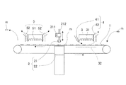
- the powder coating process in which the sintered magnet body is heated or heated in advance, the slurry is applied, and dried can be performed using, for example, a coating apparatus shown in FIGS.
- FIGS. 1 to 3 are schematic views showing a rare earth compound coating apparatus according to an embodiment of the present invention.
- This coating apparatus applies the slurry to only one side of a square block-shaped sintered magnet body by roller coating.
- reference numeral 1 denotes a transport conveyor for placing and transporting the sintered magnet body m.
- the sintered magnet body m that is intermittently driven and placed on the upper surface by a drive source (not shown) is intermittently horizontally transported. It is like that. Then, the sintered magnet body m is supplied and conveyed to the upstream end portion (right end portion in FIGS.
- the sintered magnet body is heated or heated during the conveyance,
- the slurry is applied and dried to apply the powder containing the rare earth compound, and the sintered magnet body m to which the powder is applied is formed from the downstream end (the right end in FIGS. 1 and 2) of the conveyor 1. It is like that.
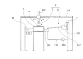
- the slurry application unit 2 includes an application roller 21 and a slurry supply mechanism 22 that impregnates the application roller 21 with slurry as needed.
- the application roller 21 is suspended on a horizontal shaft 211 and a vertical shaft 212, and is movable in the horizontal direction and the vertical direction above the transport conveyor 1 at the intermediate portion in the transport direction, as indicated by arrows in the drawing. Yes.
- the slurry supply mechanism unit 22 is configured by connecting a slurry outflow tank 221 and a slurry receiving tank 222 with a shallow slurry supply butt 223, and is located at a position where the application roller 21 is disposed, and is one of the conveyors 1. It is arranged close to the side.
- the upper end opening surface of the slurry outflow tank 221 is disposed at a position higher than the upper end opening surface of the slurry receiving tank 222, and the slurry s overflowing from the slurry outflow tank 221 passes through the slurry supply butt 223 to the slurry.
- the slurry s flows into the receiving tank 222 and is returned to the slurry outflow tank 221 from the slurry receiving tank 222 by the pump 224 and the return pipe 225 so that the slurry s circulates.
- the slurry supply butt 223 is formed with a slurry pool that slowly flows in layers.
- the application roller 21 moves horizontally and vertically, so that the roller portion is immersed in the slurry supply butt 223 and the application roller 21 is impregnated with the slurry s, and the application roller 21 again moves vertically and horizontally.
- the slurry is applied to the sintered magnet body m on the conveyor 1 with a roller.
- reference numeral 23 denotes an ultrasonic cleaner that is located near the other side of the conveyor 1 at the position where the application roller 21 is provided. Washing with a washing machine prevents the slurry coating from becoming non-uniform due to powder sticking or the like. This roller cleaning is usually performed when the coating operation is stopped.
- the application roller 21 is not particularly limited, and can be selected from known rollers such as a so-called application roller, sponge roller, rubber roller, resin roller, and metal roller in which a variety of hairs are planted.
- a sponge roller that is easily impregnated with slurry and is easy to periodically clean is employed.
- the width of the roller may be appropriately set according to the size and shape of the sintered magnet body m. However, in order to more surely apply the uniform slurry, it is preferably 10 mm to 300 mm, more preferably. Is 30 to 100 mm.
- reference numeral 3 denotes preheating means disposed on the conveying conveyor 1 on the upstream side in the conveying direction with respect to the slurry applying means 2.
- the preheating means 3 is placed on the conveying conveyor 1 by an infrared heater 31.
- the sintered magnet body m is irradiated with infrared rays to heat or heat the sintered magnet body m to the predetermined temperature described above.
- a sheet-like laminar airflow is blown onto the sintered magnet body m conveyed under the preheating unit 3 to remove dust and the like adhering to the surface of the sintered magnet body m.
- the air knife 41 is disposed, and dust collecting ducts 42 are disposed near the downstream side of the preheating means 3 to suck and remove the airflow including dust removed from the conveyor 1.
- the air knife 41 and the dust collection duct 42 constitute a cleaning means 4 for cleaning the surface of the sintered magnet body m.
- reference numeral 5 denotes drying means disposed on the transport conveyor 1 on the downstream side in the transport direction with respect to the slurry applying means 2, and an infrared heater 51 and an exhaust duct disposed on both upstream and downstream sides thereof. 52, 52.
- This drying means 5 irradiates and heats the sintered magnet body m on the conveyor 1 from the infrared heater 51 and heats it, and evaporates and removes the solvent of the slurry applied to the sintered magnet body m.
- the powder containing the rare earth compound is applied, and the solvent evaporated at this time is exhausted by the exhaust ducts 52, 52, thereby removing the vaporized solvent from the periphery of the sintered magnet body m and drying effectively. Is supposed to do.
- the infrared heaters 31 and 51 constituting the preheating means 3 and the drying means 5 are not particularly limited, but it is preferable to irradiate near infrared rays having a wavelength of 0.8 to 5 ⁇ m.
- a short wavelength infrared heater unit made of transparent quartz glass (ZKB 1500 / 200G with cooling fan, output 1500 W, heating length 200 mm) of Heraeus Twin Tube is used for both of the infrared heaters 31 and 51.
- This heater that irradiates infrared rays with a short wavelength of 0.8 to 5 ⁇ m has a fast rise and can start effective heating in 1 to 2 seconds, and can also be heated to 100 ° C. within 10 seconds.
- the sintered magnet body can be heated or heated in an extremely short time. Furthermore, it can be configured at a lower cost than when induction heating is performed, which is advantageous in terms of power consumption.
- near infrared rays can pass through and be absorbed inside the slurry coating during heating drying, so that drying can be performed by applying hot air from the outside, for example.
- cracks can be prevented from occurring as much as possible by starting to dry from the outside of the coating film as in the case of carrying out, and a uniform and dense powder coating film can be formed. Furthermore, the heater tube that generates the short-wavelength near infrared rays is relatively small, which contributes to the downsizing of the coating apparatus.
- the R 2 oxide, fluoride, oxyfluoride, hydroxide or hydride (R 2 is selected from rare earth elements including Y and Sc) on the surface of the sintered magnet body m.
- a powder rare earth compound powder
- a sintered magnet body m is supplied to the upstream end of the conveyor 1.
- the conveyor 1 is intermittently conveyed in the horizontal direction.
- the sintered magnet body m placed on the conveyor 1 and horizontally conveyed intermittently is stopped intermittently under the preheating means 3, the sintered magnet body m receives infrared rays from the infrared heater 31 of the preheating means 3. Is irradiated and heated or heated to the predetermined temperature described above. At this time, the cleaning means 4 removes dust and the like on the surface of the sintered magnet body m as described above, and the sintered magnet body m is heated or heated and the surface is cleaned.
- the application roller 21 is heated or heated to a predetermined temperature in advance by the vertical movement and horizontal movement of the application roller 21. It is applied to the surface of the sintered magnet body m.
- the application roller 21 is supplied and impregnated with the slurry s as needed by the above-described procedure by the slurry supply mechanism unit 22, and a certain amount of the slurry s is always applied reliably.
- the sintered magnet body m coated with the slurry s is then conveyed under the drying means 5 and stopped intermittently.
- the infrared heater 51 of the drying means 5 irradiates infrared rays and is heated and dried.
- the solvent evaporates and the powder is applied, and a coating film of the powder is formed on the surface of the sintered magnet body m.
- the solvent evaporated and evaporated at this time is exhausted by the exhaust duct 52 and removed from the periphery of the sintered magnet body m, and the drying process is efficiently performed.
- the dried sintered magnet body m is further horizontally transported and collected at the downstream end of the transport conveyor 1 by an operator, a robot arm, or the like.
- the sintered magnet body m recovered from the downstream end of the conveyor 1 is supplied to the upstream end of the conveyor 1 again, and the rare earth compound coating operation is repeated a plurality of times to obtain the rare earth compound powder.
- the repetition of the coating operation may be performed a plurality of times using the same coating device, or a plurality of coating devices may be arranged in parallel to repeat the coating operation. Thereby, it can apply
- both the front and back sides of the coating process may be performed using the same coating apparatus, or the front and back side of the coating apparatus may be applied in parallel with the front side coating apparatus and the back side coating apparatus.
- the above-described overcoating may be performed on both the front and back surfaces.
- the sintered magnet body m is heated to a predetermined temperature or heated before the slurry is applied. Or the slurry s is applied to the heated sintered magnet body m and dried to form a coating film of a rare earth compound powder. And by heating the sintered magnet body m in advance, the drying can be completed in a very short time during the heat drying after the slurry application.
- the drying means 5 of the present apparatus by infrared irradiation, Since the solvent of the slurry can be evaporated and dried almost instantaneously, the slurry s does not sag on unnecessary side portions, and a uniform coating can be formed efficiently and reliably. is there.
- the slurry is partially applied only to the necessary portion on the surface of the sintered magnet body m, and the coating film is partially formed on the necessary portion.
- drying after slurry application is completed in a very short time as described above. Therefore, it is possible to prevent the dripping of the slurry to the side part that does not require an increase in coercive force as much as possible, and to prevent wasteful consumption of powder containing precious rare earth compounds.
- the coercive force can be increased.
- preheating (heating) before slurry application and heat drying after application are performed by radiant heating that irradiates near-infrared rays with a short wavelength of 0.8 to 5 ⁇ m.
- preheating (heating) and heat drying can be performed, and a uniform coating film with the above powder can be reliably obtained without causing cracks, and the coating apparatus can be further downsized.
- the infrared heaters 31 and 51 that irradiate the short-wavelength near-infrared rays start up quickly and can complete heating and heating in a very short time. Furthermore, it can be configured at a lower cost than when induction heating is performed, which is advantageous in terms of power consumption. Therefore, the powder can be applied by heating or heating the sintered magnet body s more efficiently at a lower cost and drying the slurry s. Furthermore, according to the drying treatment by radiant heating by the near infrared irradiation, the near infrared rays can be transmitted and absorbed into the slurry coating and heated or heated, for example, heated by applying hot air from the outside.
- the heater tube that generates near-infrared rays with a short wavelength is relatively small, and the dryer and coating device can be downsized, and a rare earth magnet can be efficiently manufactured with a small-scale facility.
- the coating apparatus of the present invention is not limited to the apparatus shown in FIGS. 1 to 3 described above.
- a belt conveyor is shown as the conveyor 1 in the figure, a roller conveyor can be used.
- a reflective sheet 32 may be provided on the back side of the conveyor belt to reflect infrared rays, and the sintered magnet body m may be heated or heated more efficiently.
- the application roller 21 is used to apply the roller.
- spray application or immersion application may be performed.
- Other configurations such as the means 5 and the slurry supply mechanism 22 may be appropriately changed without departing from the gist of the present invention.
- the sintered magnet body coated with the above powder is heat-treated to absorb and diffuse the rare earth element indicated by R 2 in the powder.
- the heat treatment for absorbing and diffusing the rare earth element represented by R 2 may be performed according to a known method. Further, after the heat treatment, known post-treatment can be performed as necessary, such as aging treatment under appropriate conditions or further grinding into a practical shape.
- Examples 1 to 4 and Comparative Example A thin plate-like alloy in which Nd is 14.5 atomic%, Cu is 0.2 atomic%, B is 6.2 atomic%, Al is 1.0 atomic%, Si is 1.0 atomic%, and Fe is the balance.
- strip casting method in which Nd, Al, Fe, Cu metal with a purity of 99% by mass or more, high-frequency dissolution in an Ar atmosphere using 99.99% by mass of Si, ferroboron, and then poured into a single copper roll A thin plate-like alloy was used. The obtained alloy was exposed to hydrogenation of 0.11 MPa at room temperature to occlude hydrogen, then heated to 500 ° C. while evacuating to partially release hydrogen, cooled and sieved, A coarse powder of 50 mesh or less was obtained.
- the coarse powder was finely pulverized by a jet mill using high-pressure nitrogen gas to a weight-median particle size of 5 ⁇ m.
- the obtained mixed fine powder was molded into a block shape at a pressure of about 1 ton / cm 2 while being oriented in a magnetic field of 15 kOe under a nitrogen atmosphere.
- This compact was put into a sintering furnace in an Ar atmosphere and sintered at 1060 ° C. for 2 hours to obtain a magnet block.
- This magnet block was ground on the whole surface using a diamond cutter, then washed with alkaline solution, pure water, nitric acid, pure water in this order and dried to obtain a 20 mm ⁇ 45 mm ⁇ 5 mm (direction of magnetic anisotropy).
- a block magnet was obtained.
- the dysprosium fluoride powder is mixed with water at a mass fraction of 40%, and the dysprosium fluoride powder is well dispersed to prepare a slurry.
- the above-described coating apparatus shown in FIGS. The slurry was applied to the magnet body and dried to apply dysprosium fluoride powder.
- the powder coating process was performed by changing the temperature of the preheating (heating) by the preheating means 3 (Examples 1 to 4).
- coating process was performed as a comparative example, without performing the preheating (heating) by the preheating means 3 (comparative example).
- the recovered sintered magnet body was again subjected to a coating treatment, and was applied three times.
- the slurry application treatment / drying treatment was repeated three times, and the preheating treatment was performed only once for the first time.
- Table 1 shows the ratios per unit area when the coating amount at which the coercive force increasing effect peaks is 1.00.
- the slurry does not sag other than the coated surface, and the solvent is instantly dried and a coating film is formed. It was confirmed that the coating amount increased. On the other hand, in the comparative example, the amount of application is small despite the roller application similarly, and the reason is that the slurry is dripped on the side surface of the sintered magnet.
- Example 5 Further, the magnet body in which a thin film of dysprosium fluoride powder was formed in the same manner as in Example 3 was heat-treated at 900 ° C. for 5 hours in an Ar atmosphere, followed by absorption treatment at 500 ° C. for 1 hour. A rare earth magnet was obtained by rapid cooling. A magnet body was cut out at 2 mm ⁇ 2 mm ⁇ 2 mm from the nine points shown in FIG. 4 and its coercive force was measured. The results are shown in Table 2.
- the coating film of the powder is uniformly coated and formed on the surface other than the coated surface.
- the rare earth compound can be effectively utilized without waste, and the effect of increasing the coercive force on the coated surface is very stable and uniform.
Landscapes
- Engineering & Computer Science (AREA)
- Power Engineering (AREA)
- Manufacturing & Machinery (AREA)
- Mechanical Engineering (AREA)
- Chemical & Material Sciences (AREA)
- Organic Chemistry (AREA)
- Materials Engineering (AREA)
- Metallurgy (AREA)
- Inorganic Chemistry (AREA)
- Crystallography & Structural Chemistry (AREA)
- Hard Magnetic Materials (AREA)
- Manufacturing Cores, Coils, And Magnets (AREA)
- Powder Metallurgy (AREA)
Priority Applications (4)
| Application Number | Priority Date | Filing Date | Title |
|---|---|---|---|
| CN201680023908.1A CN107533908B (zh) | 2015-04-28 | 2016-04-18 | 稀土类磁铁的制造方法和稀土类化合物的涂布装置 |
| EP16786338.0A EP3291258B1 (en) | 2015-04-28 | 2016-04-18 | Method for producing rare-earth magnets, and rare-earth-compound application device |
| US15/570,243 US11224890B2 (en) | 2015-04-28 | 2016-04-18 | Method for producing rare-earth magnets, and rare-earth-compound application device |
| PH12017501974A PH12017501974A1 (en) | 2015-04-28 | 2017-10-27 | Method for producing rare-earth magnets, and rare-earth-compound application device |
Applications Claiming Priority (2)
| Application Number | Priority Date | Filing Date | Title |
|---|---|---|---|
| JP2015-091993 | 2015-04-28 | ||
| JP2015091993A JP6435982B2 (ja) | 2015-04-28 | 2015-04-28 | 希土類磁石の製造方法及び希土類化合物の塗布装置 |
Publications (1)
| Publication Number | Publication Date |
|---|---|
| WO2016175061A1 true WO2016175061A1 (ja) | 2016-11-03 |
Family
ID=57199707
Family Applications (1)
| Application Number | Title | Priority Date | Filing Date |
|---|---|---|---|
| PCT/JP2016/062194 WO2016175061A1 (ja) | 2015-04-28 | 2016-04-18 | 希土類磁石の製造方法及び希土類化合物の塗布装置 |
Country Status (7)
| Country | Link |
|---|---|
| US (1) | US11224890B2 (zh) |
| EP (1) | EP3291258B1 (zh) |
| JP (1) | JP6435982B2 (zh) |
| CN (1) | CN107533908B (zh) |
| MY (1) | MY178605A (zh) |
| PH (1) | PH12017501974A1 (zh) |
| WO (1) | WO2016175061A1 (zh) |
Cited By (3)
| Publication number | Priority date | Publication date | Assignee | Title |
|---|---|---|---|---|
| WO2018088392A1 (ja) * | 2016-11-09 | 2018-05-17 | Tdk株式会社 | 希土類磁石の製造方法 |
| EP3120935B1 (en) * | 2015-08-20 | 2018-07-11 | Tianhe (Baotou) Advanced Tech Magnet Co., Ltd. | Spraying device and use thereof |
| CN115637065A (zh) * | 2022-09-29 | 2023-01-24 | 包头市安德窑炉科技有限公司 | 一种含氧化铈铁渣在制备辐射材料中的应用 |
Families Citing this family (1)
| Publication number | Priority date | Publication date | Assignee | Title |
|---|---|---|---|---|
| KR102057870B1 (ko) * | 2019-04-04 | 2019-12-20 | 성림첨단산업(주) | 희토류 영구자석의 제조방법 |
Citations (4)
| Publication number | Priority date | Publication date | Assignee | Title |
|---|---|---|---|---|
| JPH0281661U (zh) * | 1988-07-14 | 1990-06-25 | ||
| JPH09180920A (ja) * | 1995-12-25 | 1997-07-11 | Daidoo Denshi:Kk | 希土類ボンド磁石およびその製造方法ならびに希土類ボンド磁石の熱処理装置 |
| WO2011108704A1 (ja) * | 2010-03-04 | 2011-09-09 | Tdk株式会社 | 希土類焼結磁石及びモータ |
| JP2013236071A (ja) * | 2012-04-11 | 2013-11-21 | Shin Etsu Chem Co Ltd | 希土類焼結磁石及びその製造方法 |
Family Cites Families (17)
| Publication number | Priority date | Publication date | Assignee | Title |
|---|---|---|---|---|
| US3523040A (en) | 1967-02-24 | 1970-08-04 | Magnetics Inc | Method of sealing a magnetic core |
| JPS52130019A (en) * | 1976-04-24 | 1977-11-01 | Eiichi Miyake | Dipping tanks |
| US4949667A (en) | 1988-04-20 | 1990-08-21 | Dainippon Screen Mfg. Co., Ltd. | Roll coating apparatus for forming a film of a high viscosity coating liquid on a surface |
| JPH03118873A (ja) * | 1989-09-29 | 1991-05-21 | Ndc Co Ltd | 多孔質体の塗装方法 |
| US5049453A (en) * | 1990-02-22 | 1991-09-17 | Nippon Steel Corporation | Galvannealed steel sheet with distinguished anti-powdering and anti-flaking properties and process for producing the same |
| US5869148A (en) * | 1991-04-23 | 1999-02-09 | Webcraft Technologies Inc. | Process for the in-line, high speed manufacturing of magnetic products |
| JPH10124866A (ja) * | 1996-10-11 | 1998-05-15 | Sony Corp | 磁気記録媒体の製造装置 |
| US20020160231A1 (en) * | 1999-11-08 | 2002-10-31 | Schneider Jon B. | Magnetic layer with high-permeability backing |
| BRPI0506147B1 (pt) | 2004-10-19 | 2020-10-13 | Shin-Etsu Chemical Co., Ltd | método para preparar um material de ímã permanente de terra rara |
| US7559996B2 (en) | 2005-07-22 | 2009-07-14 | Shin-Etsu Chemical Co., Ltd. | Rare earth permanent magnet, making method, and permanent magnet rotary machine |
| US7806991B2 (en) | 2005-12-22 | 2010-10-05 | Hitachi, Ltd. | Low loss magnet and magnetic circuit using the same |
| US8741440B2 (en) * | 2006-03-14 | 2014-06-03 | Sang Mok Kim | Non-stick ceramic coating composition and process |
| JP4737431B2 (ja) | 2006-08-30 | 2011-08-03 | 信越化学工業株式会社 | 永久磁石回転機 |
| DE112007002168T5 (de) * | 2006-09-14 | 2009-09-10 | ULVAC, Inc., Chigasaki | Permanentmagnet und Verfahren zur Herstellung desselben |
| JP4860493B2 (ja) * | 2007-01-18 | 2012-01-25 | 株式会社アルバック | 永久磁石の製造方法及び永久磁石の製造装置 |
| CN103205142B (zh) | 2013-01-15 | 2015-05-27 | 浙江鹏孚隆科技有限公司 | 一种有机改性陶瓷不粘涂层及其涂覆方法 |
| CN103854819B (zh) | 2014-03-22 | 2016-10-05 | 沈阳中北通磁科技股份有限公司 | 一种钕铁硼稀土永磁器件的混合镀膜方法 |
-
2015
- 2015-04-28 JP JP2015091993A patent/JP6435982B2/ja active Active
-
2016
- 2016-04-18 WO PCT/JP2016/062194 patent/WO2016175061A1/ja active Application Filing
- 2016-04-18 MY MYPI2017703991A patent/MY178605A/en unknown
- 2016-04-18 EP EP16786338.0A patent/EP3291258B1/en active Active
- 2016-04-18 CN CN201680023908.1A patent/CN107533908B/zh active Active
- 2016-04-18 US US15/570,243 patent/US11224890B2/en active Active
-
2017
- 2017-10-27 PH PH12017501974A patent/PH12017501974A1/en unknown
Patent Citations (4)
| Publication number | Priority date | Publication date | Assignee | Title |
|---|---|---|---|---|
| JPH0281661U (zh) * | 1988-07-14 | 1990-06-25 | ||
| JPH09180920A (ja) * | 1995-12-25 | 1997-07-11 | Daidoo Denshi:Kk | 希土類ボンド磁石およびその製造方法ならびに希土類ボンド磁石の熱処理装置 |
| WO2011108704A1 (ja) * | 2010-03-04 | 2011-09-09 | Tdk株式会社 | 希土類焼結磁石及びモータ |
| JP2013236071A (ja) * | 2012-04-11 | 2013-11-21 | Shin Etsu Chem Co Ltd | 希土類焼結磁石及びその製造方法 |
Non-Patent Citations (1)
| Title |
|---|
| See also references of EP3291258A4 * |
Cited By (5)
| Publication number | Priority date | Publication date | Assignee | Title |
|---|---|---|---|---|
| EP3120935B1 (en) * | 2015-08-20 | 2018-07-11 | Tianhe (Baotou) Advanced Tech Magnet Co., Ltd. | Spraying device and use thereof |
| WO2018088392A1 (ja) * | 2016-11-09 | 2018-05-17 | Tdk株式会社 | 希土類磁石の製造方法 |
| JPWO2018088392A1 (ja) * | 2016-11-09 | 2019-08-08 | Tdk株式会社 | 希土類磁石の製造方法 |
| CN115637065A (zh) * | 2022-09-29 | 2023-01-24 | 包头市安德窑炉科技有限公司 | 一种含氧化铈铁渣在制备辐射材料中的应用 |
| CN115637065B (zh) * | 2022-09-29 | 2023-10-13 | 包头市安德窑炉科技有限公司 | 一种含氧化铈铁渣在制备辐射材料中的应用 |
Also Published As
| Publication number | Publication date |
|---|---|
| JP2016207977A (ja) | 2016-12-08 |
| US20180141072A1 (en) | 2018-05-24 |
| CN107533908A (zh) | 2018-01-02 |
| JP6435982B2 (ja) | 2018-12-12 |
| PH12017501974A1 (en) | 2018-03-26 |
| CN107533908B (zh) | 2021-03-12 |
| EP3291258B1 (en) | 2022-08-31 |
| EP3291258A4 (en) | 2019-01-23 |
| EP3291258A1 (en) | 2018-03-07 |
| MY178605A (en) | 2020-10-17 |
| US11224890B2 (en) | 2022-01-18 |
Similar Documents
| Publication | Publication Date | Title |
|---|---|---|
| WO2016175061A1 (ja) | 希土類磁石の製造方法及び希土類化合物の塗布装置 | |
| US9889474B2 (en) | Spraying device and use thereof | |
| EP3614403A1 (en) | Method for preparing rare earth permanent magnet material | |
| CN107533915B (zh) | 稀土类磁铁的制造方法和稀土类化合物的涂布装置 | |
| WO2016175067A1 (ja) | 希土類磁石の製造方法及びスラリー塗布装置 | |
| JP6365393B2 (ja) | 希土類磁石の製造方法及び希土類化合物の塗布装置 | |
| WO2016175059A1 (ja) | 希土類磁石の製造方法及び希土類化合物の塗布装置 | |
| EP3291261B1 (en) | Method for producing rare-earth magnets, and slurry application device | |
| CN107533909B (zh) | 稀土类磁铁的制造方法 | |
| JP6394483B2 (ja) | 希土類磁石の製造方法及び希土類化合物の塗布装置 | |
| JP2003332162A (ja) | 水系処理液の塗布方法 |
Legal Events
| Date | Code | Title | Description |
|---|---|---|---|
| 121 | Ep: the epo has been informed by wipo that ep was designated in this application |
Ref document number: 16786338 Country of ref document: EP Kind code of ref document: A1 |
|
| WWE | Wipo information: entry into national phase |
Ref document number: 15570243 Country of ref document: US Ref document number: 12017501974 Country of ref document: PH |
|
| NENP | Non-entry into the national phase |
Ref country code: DE |