WO2016174971A1 - 電動工具 - Google Patents
電動工具 Download PDFInfo
- Publication number
- WO2016174971A1 WO2016174971A1 PCT/JP2016/059689 JP2016059689W WO2016174971A1 WO 2016174971 A1 WO2016174971 A1 WO 2016174971A1 JP 2016059689 W JP2016059689 W JP 2016059689W WO 2016174971 A1 WO2016174971 A1 WO 2016174971A1
- Authority
- WO
- WIPO (PCT)
- Prior art keywords
- motor
- speed
- rotation
- rotation speed
- control unit
- Prior art date
- Legal status (The legal status is an assumption and is not a legal conclusion. Google has not performed a legal analysis and makes no representation as to the accuracy of the status listed.)
- Ceased
Links
Images




Classifications
-
- H—ELECTRICITY
- H02—GENERATION; CONVERSION OR DISTRIBUTION OF ELECTRIC POWER
- H02P—CONTROL OR REGULATION OF ELECTRIC MOTORS, ELECTRIC GENERATORS OR DYNAMO-ELECTRIC CONVERTERS; CONTROLLING TRANSFORMERS, REACTORS OR CHOKE COILS
- H02P29/00—Arrangements for regulating or controlling electric motors, appropriate for both AC and DC motors
-
- B—PERFORMING OPERATIONS; TRANSPORTING
- B25—HAND TOOLS; PORTABLE POWER-DRIVEN TOOLS; MANIPULATORS
- B25F—COMBINATION OR MULTI-PURPOSE TOOLS NOT OTHERWISE PROVIDED FOR; DETAILS OR COMPONENTS OF PORTABLE POWER-DRIVEN TOOLS NOT PARTICULARLY RELATED TO THE OPERATIONS PERFORMED AND NOT OTHERWISE PROVIDED FOR
- B25F5/00—Details or components of portable power-driven tools not particularly related to the operations performed and not otherwise provided for
-
- B—PERFORMING OPERATIONS; TRANSPORTING
- B24—GRINDING; POLISHING
- B24B—MACHINES, DEVICES, OR PROCESSES FOR GRINDING OR POLISHING; DRESSING OR CONDITIONING OF ABRADING SURFACES; FEEDING OF GRINDING, POLISHING, OR LAPPING AGENTS
- B24B23/00—Portable grinding machines, e.g. hand-guided; Accessories therefor
- B24B23/02—Portable grinding machines, e.g. hand-guided; Accessories therefor with rotating grinding tools; Accessories therefor
-
- B—PERFORMING OPERATIONS; TRANSPORTING
- B24—GRINDING; POLISHING
- B24B—MACHINES, DEVICES, OR PROCESSES FOR GRINDING OR POLISHING; DRESSING OR CONDITIONING OF ABRADING SURFACES; FEEDING OF GRINDING, POLISHING, OR LAPPING AGENTS
- B24B23/00—Portable grinding machines, e.g. hand-guided; Accessories therefor
- B24B23/02—Portable grinding machines, e.g. hand-guided; Accessories therefor with rotating grinding tools; Accessories therefor
- B24B23/022—Spindle-locking devices, e.g. for mounting or removing the tool
-
- H—ELECTRICITY
- H02—GENERATION; CONVERSION OR DISTRIBUTION OF ELECTRIC POWER
- H02K—DYNAMO-ELECTRIC MACHINES
- H02K7/00—Arrangements for handling mechanical energy structurally associated with dynamo-electric machines, e.g. structural association with mechanical driving motors or auxiliary dynamo-electric machines
- H02K7/14—Structural association with mechanical loads, e.g. with hand-held machine tools or fans
- H02K7/145—Hand-held machine tool
-
- H—ELECTRICITY
- H02—GENERATION; CONVERSION OR DISTRIBUTION OF ELECTRIC POWER
- H02P—CONTROL OR REGULATION OF ELECTRIC MOTORS, ELECTRIC GENERATORS OR DYNAMO-ELECTRIC CONVERTERS; CONTROLLING TRANSFORMERS, REACTORS OR CHOKE COILS
- H02P27/00—Arrangements or methods for the control of AC motors characterised by the kind of supply voltage
- H02P27/04—Arrangements or methods for the control of AC motors characterised by the kind of supply voltage using variable-frequency supply voltage, e.g. inverter or converter supply voltage
- H02P27/06—Arrangements or methods for the control of AC motors characterised by the kind of supply voltage using variable-frequency supply voltage, e.g. inverter or converter supply voltage using DC to AC converters or inverters
-
- H—ELECTRICITY
- H02—GENERATION; CONVERSION OR DISTRIBUTION OF ELECTRIC POWER
- H02P—CONTROL OR REGULATION OF ELECTRIC MOTORS, ELECTRIC GENERATORS OR DYNAMO-ELECTRIC CONVERTERS; CONTROLLING TRANSFORMERS, REACTORS OR CHOKE COILS
- H02P29/00—Arrangements for regulating or controlling electric motors, appropriate for both AC and DC motors
- H02P29/50—Reduction of harmonics
-
- H—ELECTRICITY
- H02—GENERATION; CONVERSION OR DISTRIBUTION OF ELECTRIC POWER
- H02P—CONTROL OR REGULATION OF ELECTRIC MOTORS, ELECTRIC GENERATORS OR DYNAMO-ELECTRIC CONVERTERS; CONTROLLING TRANSFORMERS, REACTORS OR CHOKE COILS
- H02P6/00—Arrangements for controlling synchronous motors or other dynamo-electric motors using electronic commutation dependent on the rotor position; Electronic commutators therefor
- H02P6/14—Electronic commutators
- H02P6/16—Circuit arrangements for detecting position
-
- Y—GENERAL TAGGING OF NEW TECHNOLOGICAL DEVELOPMENTS; GENERAL TAGGING OF CROSS-SECTIONAL TECHNOLOGIES SPANNING OVER SEVERAL SECTIONS OF THE IPC; TECHNICAL SUBJECTS COVERED BY FORMER USPC CROSS-REFERENCE ART COLLECTIONS [XRACs] AND DIGESTS
- Y02—TECHNOLOGIES OR APPLICATIONS FOR MITIGATION OR ADAPTATION AGAINST CLIMATE CHANGE
- Y02P—CLIMATE CHANGE MITIGATION TECHNOLOGIES IN THE PRODUCTION OR PROCESSING OF GOODS
- Y02P70/00—Climate change mitigation technologies in the production process for final industrial or consumer products
- Y02P70/10—Greenhouse gas [GHG] capture, material saving, heat recovery or other energy efficient measures, e.g. motor control, characterised by manufacturing processes, e.g. for rolling metal or metal working
Definitions
- the present invention relates to a power tool such as a grinder capable of setting a rotation speed of a motor according to an operator's dial operation or the like.
- an electric tool such as a grinder
- a speed change function capable of setting the rotation speed of a motor in accordance with the operating state of speed setting means such as a dial.
- speed setting means such as a dial.
- a loud noise may be generated due to resonance (resonance) caused by rotation of the rotor.
- the speed at which the loud sound is generated varies depending on the size, shape, material, etc. of the housing and motor.
- the brushless motor is more efficient than a motor with a brush, and the motor can be downsized, so the natural frequency of the stator is low and the number of poles is high. Due to these factors, there is a high possibility that resonance (resonance) will occur in the practical rotational speed region of the electric power tool.
- the present invention has been made in view of such a situation, and an object thereof is to provide an electric tool capable of reducing noise while using a wide range of rotation speeds.
- the electric tool includes a motor having a stator and a rotor, a housing for housing the motor and fixing the stator, a trigger switch provided in the housing, operable by an operator, and outputting an on / off signal of the motor And a speed setting unit operated by an operator, and a control unit that sets a rotation speed of the motor according to an operation state of the speed setting unit, the control unit of the motor that the stator resonates.
- the rotation speed of the motor is set avoiding a predetermined rotation speed region.
- the speed setting means has an operation unit whose relative position with respect to the housing changes when operated by an operator, and the control unit sets a rotation speed of the motor according to the position of the operation unit, At least a part of the rotational speed excluding the predetermined rotational speed region, the rotational speed of the motor may be continuously changed according to the position of the operation unit.
- the control unit includes a storage unit that stores a value of a speed setting signal corresponding to an operation state of the speed setting unit and a set rotation speed of the motor in association with each other, and corresponds to the operation state of the speed setting unit.
- the set rotational speed may be read from the storage unit to set the rotational speed of the motor.
- the control unit may include an input terminal, and the storage content of the storage unit may be rewritten by data transmitted through the input terminal.
- Two or more of the predetermined rotational speed regions may be provided.
- An adjustment signal output unit that outputs an adjustment signal to the control unit by an operator's operation is further provided.
- the control unit receives the adjustment signal, the control unit excludes the rotation speed at the time of reception and the rotation speed in the vicinity thereof.
- the storage contents of the storage unit may be rewritable.
- the motor may be a brushless motor, and the rotor may have a permanent magnet.
- a rotation position detection unit that detects a rotation position of the rotor may be provided, and the control unit may detect a rotation speed of the motor based on an output signal of the rotation position detection unit.
- the housing may be made of a resin material.
- a speed reducer that decelerates rotation of the rotor; a spindle that is connected to the speed reducer and extends in a direction substantially perpendicular to the rotation axis of the rotor; and a tip tool attached to the spindle; and the housing has a handle May be used as
- the tip tool may have a disk shape and a diameter of 100 mm to 250 mm.
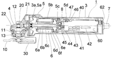
- FIG. 3 is a side sectional view of the grinder 1 in a state where the operation switch 5 is turned on.
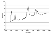
- FIG. The characteristic view which shows the relationship between the rotation speed of the motor 6 of the grinder 1, and the produced
- Explanatory drawing which shows the 1st example of the content of the table memorize
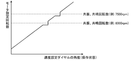
- FIG. 6 is a set speed characteristic diagram showing a first example of the relationship between the angle (operation state) of the speed setting dial 62 and the set speed of the motor 6 shown in FIG.
- FIG. 10 is a set rotational speed characteristic diagram showing a fourth example of the relationship between the angle (position) of the speed setting dial 62 and the set rotational speed of the motor 6 shown in FIG.
- FIG. 4 is a flowchart of an adjustment mode for rewriting the stored contents of the storage unit 54a of FIG.
- FIG. 11 is a set rotational speed characteristic diagram when the resonance rotational speed changes due to secular change or the like in FIG. 10.
- FIG. 13 is a set rotational speed characteristic diagram after executing the adjustment mode from the state of FIG. 12 and partially changing the set rotational speed of the motor 6.
- FIG. 1 is a side sectional view of the grinder 1 according to Embodiment 1 of the present invention in a state in which the operation switch 5 is turned off.
- FIG. 2 is a side sectional view of the grinder 1 with the operation switch 5 turned on.
- the grinder 1 includes a grindstone 10 as a tip tool (rotating tool) and is used for a grinding operation for flattening the surface of concrete, stone, or the like.
- the grindstone 10 has a disk shape and a diameter of, for example, 100 mm to 250 mm.
- a disc-shaped brush or cutter can be attached as the tip tool.
- the grinder 1 includes a housing 3 (for example, made of resin) and a gear case 4.
- the housing 3 has a substantially cylindrical shape as a whole, and a motor (electric motor) 6 as a prime mover is accommodated in the housing 3.
- the motor 6 is connected to an external AC power source such as a commercial power source via a power cord 7 drawn from the rear end of the housing 3.
- a first bevel gear 21 is provided at the front end of the output shaft 6 a of the motor 6.
- the housing 3 is provided with an operation switch (trigger switch) 5 for switching whether the motor 6 is energized (driving or stopping the motor 6).
- the operation switch 5 is urged rearward (in the direction of turning off) by the spring 5c, but the operation switch 5 is slid forward, and the locking projection 5a is locked to the locking recess of the housing 3 as shown in FIG. By hooking on 3a, the operation switch 5 can be locked in the ON state.
- the gear case 4 is made of a metal such as an aluminum alloy, and is attached to the front end portion of the housing 3.
- the opening of the gear case 4 is closed by a packing land 11 as a lid member.
- the packing land 11 is fixed to the gear case 4 by, for example, screwing.
- the packing land 11 serves as a holding member that holds a foil guard 30 described later.
- Two bearings needle bearing 12 and ball bearing 13 are provided inside the gear case 4, and the spindle 20 is rotatably held by these bearings.
- the spindle 20 is substantially orthogonal to the output shaft 6a (rotor rotating shaft) of the motor 6, and one end of the spindle 20 protrudes outside through the packing land 11.
- a second bevel gear 22 that meshes with a first bevel gear 21 attached to the output shaft 6 a of the motor 6 is provided (attached) to the other end of the spindle 20 positioned in the gear case 4.
- the rotation of the motor 6 is converted to 90 degrees by the first bevel gear 21 and the second bevel gear 22 as a speed reduction unit, and the rotation speed is reduced and transmitted to the spindle 20. That is, the spindle 20 is rotationally driven by the motor 6.
- the grindstone 10 is fixed to the spindle 20 by a wheel washer and a lock nut, and rotates integrally with the spindle 20.
- the operation switch 5 provided in the housing 3 When the operation switch 5 provided in the housing 3 is operated, electric power is supplied to the motor 6 and the output shaft 6a of the motor 6 rotates. Then, the spindle 20 connected to the output shaft 6a via the first bevel gear 21 and the second bevel gear 22 rotates, and the grindstone 10 fixed to the spindle 20 rotates.
- a foil guard 30 that covers at least 1/2 of the outer periphery of the grindstone 10 is attached to the packing land 11. The wheel guard 30 is prevented from rotating during operation so that its rotation position does not change, and the rotation position can be changed in accordance with the work contents by releasing the rotation prevention.
- the motor 6 is a brushless motor in the present embodiment, and a rotor core 6b made of a magnetic body that rotates integrally with the output shaft 6a is provided around the output shaft 6a.
- a plurality of (for example, four) rotor magnets (permanent magnets) 6c are inserted and held in the rotor core 6b.
- a stator core 6d is provided around the rotor core 6b (fixed to the housing 3).
- the stator core 6d is provided with a stator coil 6e via an insulator 6f.
- the housing 3 holding the stator core 6d is used as a handle for the grinder 1.
- a controller box 40 is provided behind the motor 6 in the housing 3.
- the controller box 40 accommodates a main board 41, a sensor board 44, and a switch board 46.
- the main board 41 is provided with a diode bridge 42, an inverter circuit 43, a controller (microcomputer) 54 shown in FIG.
- the sensor substrate 44 faces the sensor magnet 8 provided at the rear end portion of the output shaft 6 a of the motor 6.
- three Hall ICs (magnetic sensors) 45 serving as rotational position detecting means are provided at intervals of 60 °, for example.
- the switch board 46 faces the switch magnet 5d provided at the tip of the slide bar 5b that slides in conjunction with the operation of the operation switch 5.
- Two Hall ICs (magnetic sensors) 47 are provided on the surface of the switch substrate 46 facing the switch magnet 5d.
- the switch magnet 5d faces one of the Hall ICs 47 depending on whether the operation switch 5 is turned on or off.
- a speed setting dial 62 as speed setting means operated by an operator (user) is provided (held) at the rear end of the housing 3.
- the speed setting dial 62 is a dial type variable resistor. When the speed setting dial 62 is turned, the resistance value of the variable resistor changes.
- a speed setting signal indicating a value (voltage) corresponding to the amount of rotation (operation state) of the speed setting dial 62 by the operator is input to the controller 54 shown in FIG.
- the controller 54 sets the rotational speed of the motor 6 according to the value of the input speed setting signal, that is, the operation state of the speed setting dial 62, and controls the driving of the motor 6.
- the operator can set (adjust) the rotational speed of the motor 6 (the rotational speed of the grindstone 10) to a desired speed by operating the speed setting dial 62.
- the controller 54 basically changes the rotational speed of the motor 6 continuously in accordance with the operating state of the speed setting dial 62, but avoids a predetermined rotational speed region where the noise value increases due to resonance or resonance as will be described later. To set the rotation speed of the motor 6.
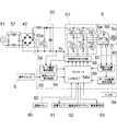
- FIG. 3 is a control block diagram of the grinder 1.
- a diode bridge 42 is connected to the AC power supply 51 via a noise reduction filter circuit 52.
- An inverter circuit 43 is provided at the output terminal of the diode bridge 42 via a power factor correction circuit 53.
- the power factor correction circuit 53 includes, for example, a transistor Tr made of a MOSFET and a gate driver IC 53a that outputs a PWM control signal to the gate of the transistor Tr.
- the harmonic current generated in each switching element of the inverter circuit 43 is less than a limit value. Has a function to suppress.
- the inverter circuit 43 is formed by connecting switching elements Tr1 to Tr6 made of, for example, MOSFETs in a three-phase bridge, and supplies a drive current to the motor 6.
- the detection resistor Rs converts the current flowing through the motor 6 into a voltage.
- the operation switch detection circuit 55 is two Hall ICs 47 mounted on the switch board 46 of FIG. 1, and a switch operation detection signal corresponding to the position (ON / OFF) of the operation switch 5 is sent to the controller (microcomputer) 54. Send.
- the controller 54 detects that the operation switch 5 is turned on by the switch operation detection signal, the controller 54 turns on the energization lamp 61.
- the speed setting dial 62 transmits a speed setting signal indicating a value corresponding to the operation state by the operator to the controller 54.
- the controller 54 has a storage unit 54a that stores the value (level) of the speed setting signal and the set rotational speed of the motor 6 as a table, and sets according to the operation state of the speed setting dial 62 by the operator.
- the rotation speed is read from the storage unit 54a and the rotation speed of the motor 6 is set.
- the storage unit 54a basically stores a set rotational speed that continuously changes in accordance with a change in the value of the speed setting signal. As described later, a predetermined rotational speed at which the noise value increases due to resonance or resonance.
- the set rotation speed is stored so as to avoid the area.
- the motor current detection circuit 56 specifies the current flowing through the motor 6 based on the terminal voltage of the detection resistor Rs, and transmits a motor current detection signal to the controller 54.
- the control signal output circuit (gate driver IC) 57 applies a drive signal such as a PWM signal to the gate of each switching element constituting the inverter circuit 43 under the control of the controller 54.
- the rotor position detection circuit 58 detects the rotation position of the rotor of the motor 6 based on the output signal of the Hall IC 45 and transmits the rotor position detection signal to the controller 54 and the motor rotation number detection circuit 59.
- the motor rotation speed detection circuit 59 detects the rotation speed (rotation speed) of the motor 6 based on the rotor position detection signal from the rotor position detection circuit 58 and transmits the motor rotation speed detection signal to the controller 54.
- the controller 54 controls the control signal output circuit 57 in accordance with the switch operation detection signal, the motor current detection signal, the rotor position detection signal, the motor rotation number detection signal, and the position (operation state) of the speed setting dial 62, Each switching element which comprises the inverter circuit 43 is driven, and the motor 6 is rotationally driven.
- the controller 54 notifies the operator of the rotation speed of the motor 6 by the speed display unit 63.
- An adjustment button (adjustment switch) 60 as an adjustment signal output unit is provided on the main board 41, and an operation unit for an operator to issue an instruction to start, end, and rewrite an adjustment mode for rewriting the storage contents of the storage unit 54a. It is.
- the input unit (input terminal) 64 is a terminal for inputting new table data to the storage unit 54a, and the controller 54 stores the storage contents of the storage unit 54a according to the table data transmitted via the input unit 64. It can be rewritten.
- FIG. 4 is a characteristic diagram showing the relationship between the number of rotations of the motor 6 and the generated sound volume in the grinder 1.
- a loud sound close to 90 dB is generated when the rotation speed of the motor 6 is around 6000 rpm and around 7500 rpm. This is due to resonance (resonance) of the stator of the motor 6.
- the motor 6 as a driving source is a brushless motor, vibration due to a magnetic attraction force (cogging torque) between the rotor and the stator is also overlapped, and a high-pitched sound with a bad ear is generated.
- the motor 6 is configured to continuously change the rotation speed of the motor 6 in accordance with the operation state of the speed setting dial 62, while avoiding the vicinity of 6000 rpm and 7500 rpm where loud noise is generated. Set the rotation speed of 6, reduce the noise while using a wide range of rotation speed.
- FIG. 5 is an explanatory diagram showing a first example of the contents of the table stored in the storage unit 54a of FIG.
- the level of the speed setting signal is a decimal value representing a value obtained by converting the output signal of the speed setting dial 62, which is an analog signal, into a 10-bit digital signal.
- the speed setting signal level is shown in increments of 10 in FIG. 5, it is actually stored in the storage unit 54a in increments of 1.
- the range of 400 rpm before and after 6000 rpm and 7500 rpm, where a loud sound is generated by resonance (resonance) is excluded from the set rotation speed, and in the other ranges, the set rotation speed is increased every time the level of the speed setting signal increases.
- the memory content is up 10rmp. Specifically, when the level of the speed setting signal exceeds 460 and is less than 540, a setting rotational speed (5600 rpm) equivalent to the case where the level of the speed setting signal is 460 is stored, and the level of the speed setting signal is 540. Then, the set rotation speed increases 800 rpm at a stretch, and 6400 rpm is stored. Similarly, when the speed setting signal level exceeds 610 and is less than 690, the same setting speed (7100 rpm) as when the speed setting signal level is 610 is stored, and the speed setting signal level is set at 690. The rotation speed increases 800 rpm at a stretch, and 7900 rpm is stored. In the example of FIG.
- the set rotational speed in the range of 400 rpm before and after 6000 rpm or 7500 rpm is stored if the rule is that the set rotational speed increases by 10 rmp each time the speed setting signal level increases by 1 (normal continuous change).
- the set rotational speed (5600 rpm or 7100 rpm) immediately before the range is stored. Since the controller 54 reads the set rotational speed according to the level of the speed setting signal from the storage unit 54a and sets the rotational speed of the motor 6, the rotational speed of the motor 6 is 6000rpm at which a loud sound is generated due to resonance (resonance). And it is set to avoid the range of 400rpm before and after 7500rpm.
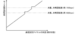
- FIG. 6 is a set rotation speed characteristic diagram showing a first example of the relationship between the angle (operation state) of the speed setting dial 62 and the set rotation speed of the motor 6 shown in FIG.
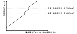
- FIG. 7 is a set rotational speed characteristic diagram showing the second example.
- FIG. 8 is a set rotational speed characteristic diagram showing the third example.
- the first example shown in FIG. 6 corresponds to the case where the contents of the table in the storage unit 54a are as shown in FIG.
- the second example shown in FIG. 7 in the table of the storage unit 54a, if the normal continuous change, the set rotation speed immediately after the range is stored in the portion where the set rotation speed in the range of 400rpm before and after 6000rpm or 7500rpm is stored.
- the third example shown in FIG. 8 corresponds to the case where the table in the storage unit 54a has a content in which the range of 400 rpm before and after 6000 rpm or 7500 rpm is skipped without providing a range in which the set rotational speed is constant.
- the motor 6 rotates at a rotational speed that avoids the range of 400 rpm before and after 6000 rpm and 7500 rpm where a loud sound is generated, noise is suppressed.
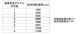
- FIG. 9 is an explanatory diagram showing a second example of the contents of the table stored in the storage unit 54a of FIG.
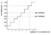
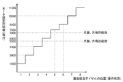
- FIG. 10 is a set rotation speed characteristic diagram showing a fourth example of the relationship between the angle (position) of the speed setting dial 62 and the set rotation speed of the motor 6 shown in FIG. 5 to 8 correspond to the case where the rotation amount of the speed setting dial 62 continuously changes, whereas in the examples of FIGS. 9 and 10, the rotation amount of the speed setting dial 62 is stepped. This corresponds to a case where the target changes (eight steps as an example here).
- FIGS. 10 is a set rotation speed characteristic diagram showing a fourth example of the relationship between the angle (position) of the speed setting dial 62 and the set rotation speed of the motor 6 shown in FIG. 5 to 8 correspond to the case where the rotation amount of the speed setting dial 62 continuously changes, whereas in the examples of FIGS. 9 and 10, the rotation amount of the speed setting dial 62 is stepped. This corresponds to a case where the target changes (eight steps
- FIG. 11 is a flowchart of an adjustment mode for rewriting the stored contents of the storage unit 54a of FIG.
- This flowchart shows the flow of control when the operator rewrites the table of the storage unit 54a shown in FIG.
- the controller 54 detects that the adjustment button 60 has been pressed for a long time (S1, Yes), that is, upon receiving an adjustment mode start signal, the controller 54 starts the adjustment mode.
- the controller 54 initializes the table in the storage unit 54a (S2) and starts the motor 6 (S3).
- the initialization of the table is performed by storing the set rotational speed according to the rule that the set rotational speed increases by 10 rmp every time the speed setting signal level increases by 1 for the entire range of the speed setting signal level. is there.
- the controller 54 drives the motor 6 at a rotational speed corresponding to the operation amount of the speed setting dial 62 (S4), and detects that the adjustment button 60 is pressed for a short time during the driving of the motor 6 (S5, Yes). That is, when the adjustment signal is received, the contents of the table are rewritten (S6). Specifically, the controller 54 replaces the set rotational speed in the range of, for example, 400 rpm before and after the rotational speed of the motor 6 when the adjustment button 60 is pressed for a short time with the rotational speed immediately before or after the range, for example. The operator can exclude a plurality of different rotation speed ranges from the set rotation speed by changing the speed setting dial 62 and pressing the adjustment button 60 again for a short time.
- the controller 54 When the controller 54 detects that the adjustment button 60 has been pressed for a long time (S7, Yes), that is, when it receives the adjustment mode end signal, it stops the motor 6 (S8) and ends the adjustment mode.
- the adjustment mode start signal and the adjustment mode end signal are signals indicating the same level change, and are processed as the adjustment mode start signal when the adjustment mode is not executed, and the adjustment mode ends while the adjustment mode is being executed. It is processed as a signal.
- FIG. 12 is a set rotational speed characteristic diagram when the resonance rotational speed changes due to secular change or the like in FIG.
- the wear of parts may progress or the housing 3 may be deformed, and the resonance rotational speed at which a loud sound is generated may change.
- the resonance rotational speed can be changed by component replacement.
- FIG. 12 shows a case where the set rotational speed when the position of the speed setting dial 62 is “4” and “5” has become a rotational speed at which a loud sound is generated due to resonance, due to secular change or the like.
- FIG. 12 is the same as FIG. 10 except that the resonance rotational speed is changed.
- FIG. 13 is a set rotational speed characteristic diagram after the adjustment mode is executed from the state of FIG. 12 and the set rotational speed of the motor 6 is partially changed.
- the operator presses the adjustment button 60 for a short time when the position of the speed setting dial 62 is “4” and “5” in the adjustment mode, so that the position of the speed setting dial 62 is “ The case where the set rotational speed at the time of “4” and “5” is shifted higher by 500 rpm is shown. As a result, noise can be reduced even when the resonance rotational speed at which secular change or the like has occurred changes.
- soot controller 54 sets the rotational speed of the motor 6 while avoiding a predetermined rotational speed region where a loud sound is generated due to resonance (resonance), the noise can be reduced while using a wide range of rotational speeds. .
- These effects are small, like a portable power tool, with a low-rigidity housing that tends to resonate, or with a brushless motor as a drive source and electromagnetic vibration (vibration using cogging torque as an excitation force) This is particularly noticeable in power tools that generate high-pitched sounds.
- the predetermined rotational speed region excluded from the set rotational speed may be one or three or more.
- the predetermined rotation speed region is not limited to the specific range exemplified in the embodiment, and may be set as appropriate in accordance with the size and shape of the housing and the motor.
- the widths of the plurality of rotation speed regions excluded from the set rotation speed do not have to be the same as each other, and may be set as appropriate for each region so that noise can be effectively reduced.
- the adjustment button 60 and the input unit 64 may be omitted if it is not necessary to rewrite the table of the storage unit 54a afterwards.
- the power tool is not limited to the grinder exemplified in the embodiment, and may be another type of power tool having a speed change function, such as a multi-cutter or a jigsaw.
- the drive source of the electric tool is not limited to a brushless motor, and may be a brush motor.
- the number of stages of the speed setting dial 62 shown in the examples of FIGS. 9 and 10 is not limited to eight, and can be set to an arbitrary plurality of stages.
- the trigger switch and the speed setting unit are configured separately. However, for example, an integrated configuration in which the set speed is changed according to the pulling amount of the trigger switch may be used. In this case, since the trigger switch also serves as the operation unit, the number of parts can be reduced.
- the adjustment button may be operable from the outside without being installed on the substrate.
Landscapes
- Engineering & Computer Science (AREA)
- Power Engineering (AREA)
- Mechanical Engineering (AREA)
- Finish Polishing, Edge Sharpening, And Grinding By Specific Grinding Devices (AREA)
- Portable Power Tools In General (AREA)
Abstract
Description
Claims (11)
- ステータとロータを有するモータと、前記モータを収容し、前記ステータを固定するハウジングと、前記ハウジングに設けられ、作業者が操作可能で、前記モータのオンオフ信号を出力するトリガスイッチと、作業者が操作する速度設定手段と、前記速度設定手段の操作状態に応じて前記モータの回転速度を設定する制御部と、を備え、前記制御部は、前記ステータが共振する前記モータの所定回転速度領域を避けて前記モータの回転速度を設定する、電動工具。
- 前記速度設定手段は、作業者が操作することで前記ハウジングに対する相対位置が変化する操作部を有し、前記制御部は、前記操作部の前記位置に応じて前記モータの回転速度を設定し、前記所定回転速度領域を除く少なくとも一部の回転速度においては、前記操作部の前記位置に応じて前記モータの回転速度を連続的に変化させる、請求項1に記載の電動工具。
- 前記制御部は、前記速度設定手段の操作状態に応じた速度設定信号の値と、前記モータの設定回転速度とを対応づけて記憶した記憶部を有し、前記速度設定手段の操作状態に応じた前記設定回転速度を前記記憶部から読み出して前記モータの回転速度を設定する、請求項1又は2に記載の電動工具。
- 前記制御部は、入力端子を有し、前記入力端子を介して送信されたデータにより前記記憶部の記憶内容を書換え可能である、請求項3に記載の電動工具。
- 前記所定回転速度領域が2つ以上である請求項1から4のいずれか一項に記載の電動工具。
- 作業者の操作により前記制御部に調整信号を出力する調整信号出力部を更に備え、前記制御部は、前記調整信号を受信すると、受信時の回転速度及びその近傍の回転速度を除外するように前記記憶部の記憶内容を書換え可能である、請求項3又は4に記載の電動工具。
- 前記モータはブラシレスモータであり、前記ロータが永久磁石を有する、請求項1から6のいずれか一項に記載の電動工具。
- 前記ロータの回転位置を検出する回転位置検出手段を備え、前記制御部は、前記回転位置検出手段の出力信号に基づいて前記モータの回転速度を検出する、請求項1から7のいずれか一項に記載の電動工具。
- 前記ハウジングが、樹脂材料からなる、請求項1から8のいずれか一項に記載の電動工具。
- 前記ロータの回転を減速する減速部と、前記減速部と接続され、前記ロータの回転軸と略直交する方向に伸びるスピンドルと、前記スピンドルに取り付けられた先端工具と、を備え、前記ハウジングがハンドルとして用いられる、請求項1から9のいずれか一項に記載の電動工具。
- 前記先端工具は、円盤形状で、直径が100mm~250mmである、請求項10に記載の電動工具。
Priority Applications (4)
| Application Number | Priority Date | Filing Date | Title |
|---|---|---|---|
| JP2017515440A JP6390884B2 (ja) | 2015-04-27 | 2016-03-25 | 電動工具 |
| US15/569,087 US20180111259A1 (en) | 2015-04-27 | 2016-03-25 | Power tool |
| CN201680023967.9A CN107530874A (zh) | 2015-04-27 | 2016-03-25 | 电动工具 |
| DE112016001933.5T DE112016001933T5 (de) | 2015-04-27 | 2016-03-25 | Elektrowerkzeug |
Applications Claiming Priority (2)
| Application Number | Priority Date | Filing Date | Title |
|---|---|---|---|
| JP2015-090862 | 2015-04-27 | ||
| JP2015090862 | 2015-04-27 |
Publications (1)
| Publication Number | Publication Date |
|---|---|
| WO2016174971A1 true WO2016174971A1 (ja) | 2016-11-03 |
Family
ID=57198660
Family Applications (1)
| Application Number | Title | Priority Date | Filing Date |
|---|---|---|---|
| PCT/JP2016/059689 Ceased WO2016174971A1 (ja) | 2015-04-27 | 2016-03-25 | 電動工具 |
Country Status (5)
| Country | Link |
|---|---|
| US (1) | US20180111259A1 (ja) |
| JP (1) | JP6390884B2 (ja) |
| CN (1) | CN107530874A (ja) |
| DE (1) | DE112016001933T5 (ja) |
| WO (1) | WO2016174971A1 (ja) |
Cited By (3)
| Publication number | Priority date | Publication date | Assignee | Title |
|---|---|---|---|---|
| WO2018180083A1 (ja) * | 2017-03-30 | 2018-10-04 | 工機ホールディングス株式会社 | 回転工具 |
| WO2019094247A1 (en) * | 2017-11-07 | 2019-05-16 | Milwaukee Electric Tool Corporation | Non-contact speed selector swtich in rotary power tool |
| JP2022112974A (ja) * | 2021-01-22 | 2022-08-03 | 株式会社マキタ | 回転工具 |
Families Citing this family (8)
| Publication number | Priority date | Publication date | Assignee | Title |
|---|---|---|---|---|
| US10404136B2 (en) * | 2015-10-14 | 2019-09-03 | Black & Decker Inc. | Power tool with separate motor case compartment |
| CN106926096B (zh) * | 2015-12-31 | 2020-01-31 | 南京德朔实业有限公司 | 角磨机 |
| TWI676348B (zh) * | 2018-05-25 | 2019-11-01 | 車王電子股份有限公司 | 電動工具 |
| US11571803B2 (en) * | 2019-05-30 | 2023-02-07 | Milwaukee Electric Tool Corporation | Power tool with combined chip for wireless communications and power tool control |
| US11858106B2 (en) | 2019-08-08 | 2024-01-02 | Black & Decker Inc. | Power tools and power tools platform |
| CN113949227B (zh) * | 2020-07-16 | 2023-07-18 | 车王电子股份有限公司 | 电动工具及其控制方法 |
| EP4063049A1 (en) * | 2021-03-24 | 2022-09-28 | Airbus Operations, S.L.U. | Device and method for drilling with automatic drilling parameters adaptation |
| CN115338760B (zh) * | 2022-09-05 | 2024-01-23 | 西南交通大学 | 气囊抛光振动抑制方法及气囊抛光设备 |
Citations (7)
| Publication number | Priority date | Publication date | Assignee | Title |
|---|---|---|---|---|
| JPS63237876A (ja) * | 1987-03-23 | 1988-10-04 | 松下電工株式会社 | ハンマ−ドリル |
| JPH06153557A (ja) * | 1992-11-06 | 1994-05-31 | Fujitsu General Ltd | 静音運転システム |
| JP2012110070A (ja) * | 2010-11-15 | 2012-06-07 | Panasonic Corp | 空気調和機 |
| JP2013000874A (ja) * | 2011-06-22 | 2013-01-07 | Panasonic Eco Solutions Power Tools Co Ltd | 電動工具 |
| EP2581168A1 (en) * | 2011-10-13 | 2013-04-17 | Oy Kwh Mirka Ab | Handheld machine |
| US20130092408A1 (en) * | 2011-10-18 | 2013-04-18 | Robert Bosch Gmbh | Semi-Active Anti-Vibration Systems for Handheld Electrical Power Tools |
| JP2013128341A (ja) * | 2011-12-16 | 2013-06-27 | Samsung Yokohama Research Institute Co Ltd | 表面磁石型のブラシレスモータ |
Family Cites Families (29)
| Publication number | Priority date | Publication date | Assignee | Title |
|---|---|---|---|---|
| US3221192A (en) * | 1962-10-11 | 1965-11-30 | Porter Co H K | Variable speed hand tool |
| US3684934A (en) * | 1971-01-11 | 1972-08-15 | Superior Electric Co | Stepping motor drive circuit with path for induced voltages |
| US3855515A (en) * | 1972-03-06 | 1974-12-17 | Waters Associates Inc | Motor control circuit |
| JPS6051500A (ja) * | 1983-08-29 | 1985-03-22 | Hitachi Ltd | ロボットの動作制御装置 |
| IN169597B (ja) * | 1986-06-19 | 1991-11-16 | Gen Electric | |
| DE3719463A1 (de) * | 1987-06-11 | 1988-12-22 | Dienes Apparatebau Gmbh | Einrichtung zur drehzahlregelung eines asynchronmotors |
| NL8800366A (nl) * | 1988-02-15 | 1989-09-01 | Emerson Electric Co | Montage-inrichting voor borstels bij een omkeerbare collectormotor. |
| JPH04112694A (ja) * | 1990-08-30 | 1992-04-14 | Zexel Corp | ブラシレスモータを用いたブロワユニットの騒音発生防止装置 |
| US5572916A (en) * | 1994-10-20 | 1996-11-12 | Hitachi Koki Haramachi Co., Ltd. | Desk-top cutting machine |
| KR100728492B1 (ko) * | 2000-04-20 | 2007-06-14 | 가부시키가이샤 야스가와덴끼 | 전동기 제어 장치 |
| US6429610B1 (en) * | 2000-09-05 | 2002-08-06 | General Electric Co. | Method and system for reducing motor vibration by controlling flux producing current |
| JP3853590B2 (ja) * | 2000-12-15 | 2006-12-06 | 株式会社マキタ | 電動工具 |
| US20020134811A1 (en) * | 2001-01-29 | 2002-09-26 | Senco Products, Inc. | Multi-mode power tool utilizing attachment |
| US7075195B2 (en) * | 2002-01-14 | 2006-07-11 | Safestart System, Llc | Electrical safety lockout mechanism for power tools and other hazardous machinery |
| US6936990B2 (en) * | 2002-03-29 | 2005-08-30 | Matsushita Electric Industrial Co., Ltd. | Method for controlling electric motor and apparatus for controlling the same |
| DE10246093C1 (de) * | 2002-10-02 | 2003-11-27 | Siemens Ag | Verfahren zur Dämpfung mechanischer Schwingungen von Achsen von Werkzeugmaschinen, Produktionsmaschinen oder Robotern |
| US7410006B2 (en) * | 2004-10-20 | 2008-08-12 | Black & Decker Inc. | Power tool anti-kickback system with rotational rate sensor |
| US7552781B2 (en) * | 2004-10-20 | 2009-06-30 | Black & Decker Inc. | Power tool anti-kickback system with rotational rate sensor |
| KR101287536B1 (ko) * | 2007-06-05 | 2013-07-18 | 삼성전자주식회사 | 세탁기 및 그 제어방법 |
| US8985068B2 (en) * | 2010-07-22 | 2015-03-24 | Robert Bosch Gmbh | Systems and methods for avoiding resonances excited by rotating components |
| WO2013059764A1 (en) * | 2011-10-21 | 2013-04-25 | Prime Datum, Inc. | Direct drive fan system with variable process control |
| US10670028B2 (en) * | 2011-10-21 | 2020-06-02 | Prime Datum Development Company, Llc | Load bearing direct drive fan system with variable process control |
| JP2013095309A (ja) * | 2011-11-02 | 2013-05-20 | Ntn Corp | インホイールモータ車両用サスペンションシステム |
| EP2809482B1 (en) * | 2012-01-30 | 2018-11-07 | Fatigue Technology, Inc. | Processing systems and method of operating the same |
| DE202014102422U1 (de) * | 2013-05-31 | 2014-08-08 | Hitachi Koki Co., Ltd. | Elektroleistungswerkzeug |
| DE102014208980A1 (de) * | 2014-01-27 | 2015-07-30 | Robert Bosch Gmbh | Werkzeugmaschinenvorrichtung |
| DE102014209009A1 (de) * | 2014-01-27 | 2015-07-30 | Robert Bosch Gmbh | Werkzeugmaschinenvorrichtung |
| JP2015182662A (ja) * | 2014-03-25 | 2015-10-22 | トヨタ自動車株式会社 | エンジン停止制御装置 |
| JP6348869B2 (ja) * | 2015-04-09 | 2018-06-27 | ミネベアミツミ株式会社 | 計器の駆動制御装置 |
-
2016
- 2016-03-25 CN CN201680023967.9A patent/CN107530874A/zh not_active Withdrawn
- 2016-03-25 WO PCT/JP2016/059689 patent/WO2016174971A1/ja not_active Ceased
- 2016-03-25 JP JP2017515440A patent/JP6390884B2/ja active Active
- 2016-03-25 US US15/569,087 patent/US20180111259A1/en not_active Abandoned
- 2016-03-25 DE DE112016001933.5T patent/DE112016001933T5/de not_active Withdrawn
Patent Citations (7)
| Publication number | Priority date | Publication date | Assignee | Title |
|---|---|---|---|---|
| JPS63237876A (ja) * | 1987-03-23 | 1988-10-04 | 松下電工株式会社 | ハンマ−ドリル |
| JPH06153557A (ja) * | 1992-11-06 | 1994-05-31 | Fujitsu General Ltd | 静音運転システム |
| JP2012110070A (ja) * | 2010-11-15 | 2012-06-07 | Panasonic Corp | 空気調和機 |
| JP2013000874A (ja) * | 2011-06-22 | 2013-01-07 | Panasonic Eco Solutions Power Tools Co Ltd | 電動工具 |
| EP2581168A1 (en) * | 2011-10-13 | 2013-04-17 | Oy Kwh Mirka Ab | Handheld machine |
| US20130092408A1 (en) * | 2011-10-18 | 2013-04-18 | Robert Bosch Gmbh | Semi-Active Anti-Vibration Systems for Handheld Electrical Power Tools |
| JP2013128341A (ja) * | 2011-12-16 | 2013-06-27 | Samsung Yokohama Research Institute Co Ltd | 表面磁石型のブラシレスモータ |
Cited By (10)
| Publication number | Priority date | Publication date | Assignee | Title |
|---|---|---|---|---|
| WO2018180083A1 (ja) * | 2017-03-30 | 2018-10-04 | 工機ホールディングス株式会社 | 回転工具 |
| JPWO2018180083A1 (ja) * | 2017-03-30 | 2019-07-11 | 工機ホールディングス株式会社 | 回転工具 |
| JP2020146837A (ja) * | 2017-03-30 | 2020-09-17 | 工機ホールディングス株式会社 | 回転工具 |
| JP7036148B2 (ja) | 2017-03-30 | 2022-03-15 | 工機ホールディングス株式会社 | 回転工具 |
| JP2022079474A (ja) * | 2017-03-30 | 2022-05-26 | 工機ホールディングス株式会社 | 回転工具 |
| US11745301B2 (en) | 2017-03-30 | 2023-09-05 | Koki Holdings Co., Ltd. | Rotary tool |
| JP7392748B2 (ja) | 2017-03-30 | 2023-12-06 | 工機ホールディングス株式会社 | 回転工具 |
| WO2019094247A1 (en) * | 2017-11-07 | 2019-05-16 | Milwaukee Electric Tool Corporation | Non-contact speed selector swtich in rotary power tool |
| JP2022112974A (ja) * | 2021-01-22 | 2022-08-03 | 株式会社マキタ | 回転工具 |
| JP7642383B2 (ja) | 2021-01-22 | 2025-03-10 | 株式会社マキタ | 回転工具 |
Also Published As
| Publication number | Publication date |
|---|---|
| US20180111259A1 (en) | 2018-04-26 |
| JP6390884B2 (ja) | 2018-09-19 |
| DE112016001933T5 (de) | 2018-02-15 |
| JPWO2016174971A1 (ja) | 2018-01-18 |
| CN107530874A (zh) | 2018-01-02 |
Similar Documents
| Publication | Publication Date | Title |
|---|---|---|
| JP6390884B2 (ja) | 電動工具 | |
| JP6414603B2 (ja) | 電動工具 | |
| JP6460354B2 (ja) | 電動工具 | |
| US20220166283A1 (en) | Brushless motor for a power tool | |
| JP6915691B2 (ja) | 電動工具 | |
| JP6753472B2 (ja) | 電動工具 | |
| JP5527488B2 (ja) | モータ駆動方法およびモータ駆動装置 | |
| CN104227673A (zh) | 具有电动驱动装置和至少一个第一壳体部件的手工工具机 | |
| JP2003199310A (ja) | ブラシレスdcモータ及び電動工具 | |
| CN106457551A (zh) | 具有作为直接驱动器的电子整流电动机的手持式工具机 | |
| JP6906196B2 (ja) | 電動工具 | |
| JP6617918B2 (ja) | 電動工具 | |
| JP2019033649A (ja) | 電動工具 | |
| US20250018533A1 (en) | Power tool with electronic control of multiple speeds | |
| JP2019107717A (ja) | 電動工具 | |
| JP2018140447A (ja) | 電動工具 | |
| WO2018230309A1 (ja) | 電動工具 | |
| JP2014133277A (ja) | 電動工具 | |
| WO2016067811A1 (ja) | 電動機器 | |
| JP5652131B2 (ja) | 電動工具 | |
| JP2016209939A (ja) | 電動工具 | |
| JP2018202499A (ja) | 電動工具 |
Legal Events
| Date | Code | Title | Description |
|---|---|---|---|
| 121 | Ep: the epo has been informed by wipo that ep was designated in this application |
Ref document number: 16786248 Country of ref document: EP Kind code of ref document: A1 |
|
| ENP | Entry into the national phase |
Ref document number: 2017515440 Country of ref document: JP Kind code of ref document: A |
|
| WWE | Wipo information: entry into national phase |
Ref document number: 15569087 Country of ref document: US |
|
| WWE | Wipo information: entry into national phase |
Ref document number: 112016001933 Country of ref document: DE |
|
| 122 | Ep: pct application non-entry in european phase |
Ref document number: 16786248 Country of ref document: EP Kind code of ref document: A1 |