WO2016174887A1 - ガラス板トレイ - Google Patents
ガラス板トレイ Download PDFInfo
- Publication number
- WO2016174887A1 WO2016174887A1 PCT/JP2016/052367 JP2016052367W WO2016174887A1 WO 2016174887 A1 WO2016174887 A1 WO 2016174887A1 JP 2016052367 W JP2016052367 W JP 2016052367W WO 2016174887 A1 WO2016174887 A1 WO 2016174887A1
- Authority
- WO
- WIPO (PCT)
- Prior art keywords
- glass plate
- region
- rough surface
- arrangement
- area
- Prior art date
- Legal status (The legal status is an assumption and is not a legal conclusion. Google has not performed a legal analysis and makes no representation as to the accuracy of the status listed.)
- Ceased
Links
Images




Classifications
-
- B—PERFORMING OPERATIONS; TRANSPORTING
- B65—CONVEYING; PACKING; STORING; HANDLING THIN OR FILAMENTARY MATERIAL
- B65D—CONTAINERS FOR STORAGE OR TRANSPORT OF ARTICLES OR MATERIALS, e.g. BAGS, BARRELS, BOTTLES, BOXES, CANS, CARTONS, CRATES, DRUMS, JARS, TANKS, HOPPERS, FORWARDING CONTAINERS; ACCESSORIES, CLOSURES, OR FITTINGS THEREFOR; PACKAGING ELEMENTS; PACKAGES
- B65D85/00—Containers, packaging elements or packages, specially adapted for particular articles or materials
- B65D85/30—Containers, packaging elements or packages, specially adapted for particular articles or materials for articles particularly sensitive to damage by shock or pressure
- B65D85/48—Containers, packaging elements or packages, specially adapted for particular articles or materials for articles particularly sensitive to damage by shock or pressure for glass sheets
Definitions
- the present invention relates to a technique for improving a glass plate tray used, for example, for conveying or storing a glass plate.
- a glass plate used for a cover glass of a solid-state imaging device such as a CCD is accommodated in a tray, and is transported and stored.
- the tray used for this purpose can usually accommodate a plurality of glass plates in a flat state. (For example, see Patent Documents 1 to 3).
- the glass plate accommodated in such a tray is usually picked up automatically by a pickup device when taken out from the tray.
- the pickup device takes an image of the glass plate and its surroundings with an imaging means.
- the pickup device recognizes the position of the glass plate based on the difference between the glass plate and the periphery in the image data formed by the imaging means.
- the pickup device picks up the glass plate based on the recognized position of the glass plate.
- an object of the present invention is to reduce errors in position recognition of a glass plate in a pickup device.
- the glass plate tray according to the present invention created to solve the above-mentioned problems, is a glass plate tray provided with a storage region capable of storing a plurality of glass plates in a flat state, and at least a part of the storage region. Further, the present invention is characterized in that a surface capable of recognizing a difference between the glass plate and its periphery is provided by image data.
- the glass plate and its periphery in the image data can be easily distinguished.
- the surface which can recognize the difference between a glass plate and its periphery by image data is provided in the accommodation area
- the surface which can recognize the difference between a glass plate and its periphery by image data can be formed by roughening at least a part of the accommodation area, providing a groove, or coloring.
- the rough surface roughness of the rough surface is rougher than the surface roughness of the glass plate, the rough surface and the glass plate in the image data can be easily distinguished.
- the rough surface is provided in the accommodation area
- the said storage area is divided into the arrangement
- region At least one part of the area
- the arrangement region is the maximum region where the glass plate can be arranged, and the glass plate may be smaller than the arrangement region in plan view due to dimensional tolerances or the like (hereinafter the same).
- the glass plate arranged in the arrangement region and the rough surface are substantially adjacent to each other in plan view. Therefore, the boundary between the glass plate and the rough surface becomes clear in the image data. Therefore, the position of the glass plate can be recognized more easily by the pickup device, and errors in the position recognition of the glass plate in the pickup device can be further reduced.
- the arrangement area is rectangular, and the rough surface is provided in the non-arrangement area adjacent to at least a part of each side of the arrangement area.
- each side of the rectangular glass plate arranged in the arrangement area is adjacent to the rough surface in plan view, so the boundary between the four sides of the glass plate and the rough surface is clear in the image data. It becomes. Therefore, the pickup device can recognize the positions of all the sides of the rectangular glass plate, thereby improving the accuracy of the position recognition of the glass plate and enabling a pickup with higher accuracy.
- the rough surface is provided only in a frame-like region including the non-arrangement region adjacent to at least a part of each side of the arrangement region.
- the rough surface that can be a dust generation source is provided only in the frame-shaped region, it is possible to reduce the rough surface to a small area. Therefore, it is possible to avoid a situation where dust is generated on a rough surface during use of the glass plate tray.
- the rough surface is preferably provided from the non-arrangement region to the arrangement region.
- FIG. 5 is a sectional view taken along line XX in FIG. 4. It is an expanded sectional view which shows typically the principal part of the laminated glass plate tray.
- FIG. 1 is a plan view showing a glass plate tray according to an embodiment of the present invention
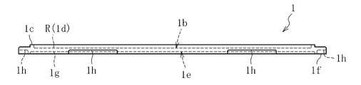
- FIG. 2 is a side view showing the glass plate tray according to the embodiment of the present invention.
- the glass plate tray 1 can be stacked in the vertical direction, and is made of a resin such as polycarbonate or ABS resin.
- the glass plate tray 1 is substantially flat as a whole, and in this embodiment is rectangular in plan view (the lateral side is the long side in FIG. 1), and the direction is identified at one of its four corners.
- a chamfered portion 1a is formed.
- a ridge 1c is provided over the entire circumference slightly closer to the center than the outer edge.
- the upper surface main region 1d on the upper surface 1b on the center side of the protruding portion 1c is a flat surface, and is a storage region R that can store a plurality of glass plates 2 in a flat state.
- the lower surface 1e of the glass plate tray 1 is provided with a raised portion 1f on the outer edge thereof over the entire circumference.
- a lower surface main region 1g at the center side of the raised portion 1f on the lower surface 1e is planar, and provided with contact portions 5 that contact the glass plates 2 when the glass plate trays 1 are stacked.
- the raised portion 1f on the lower surface 1e is provided with a plurality of concave portions 1h at predetermined positions for engaging the robot's claws.
- the inner periphery of the raised portion 1f is fitted to the outer periphery of the protruding portion 1c, the lower surface of the protruding portion 1f is in contact with the region on the outer edge side of the protruding portion 1c, and the lower surface main The region 1g is configured to come into contact with the upper surface of the ridge portion 1c.
- the stacked glass plate trays 1 are positioned in the vertical direction and the horizontal direction.
- the glass plate 2 has a rectangular shape, and the size of the glass plate 2 is 10 mm ⁇ 20 mm or more, preferably 20 mm ⁇ 30 mm or more, more preferably 30 mm ⁇ 40 mm or more. May be the size.
- the thickness of the glass plate 2 is 0.4 mm to 1.0 mm, preferably 0.5 mm to 0.9 mm, more preferably 0.6 mm to 0.8 mm, but is not limited thereto. .
- the surface roughness of the glass plate 2 is, for example, an arithmetic average roughness Ra, preferably 10.0 nm or less, more preferably 5.0 nm or less, and most preferably 2.0 nm or less.
- the definition of the arithmetic average roughness Ra conforms to JIS B 0601: 2013 (the same applies hereinafter).
- the glass plate 2 having an arithmetic average roughness Ra of 2.0 nm or less can be obtained without performing polishing, for example, if manufactured by the overflow downdraw method.
- the placement unit 3 has a hemispherical shape, but is not limited thereto, and may have a rectangular parallelepiped shape or the like.
- the positioning part 4 can come into contact with the four corners of one glass plate 2. More specifically, the side surface of one positioning portion 4 can be brought into contact with each of a pair of end surfaces constituting one corner of the glass plate 2. Thereby, the glass plate 2 is positioned in the horizontal direction by the positioning unit 4.
- the positioning portion 4 has a substantially rectangular parallelepiped shape, and in a plan view, the dimension L1 in a direction perpendicular to the side on which the glass plate 2 can come into contact. Is larger than the dimension L2 in the direction of the side where the glass plate 2 can come into contact.
- the side surface corresponding to the long side in the plan view is planar, but the side surface corresponding to the short side in the plan view is a partial cylindrical surface.
- the side surface and the upper surface of the positioning part 4 are rounded.
- the positioning part 4 is arrange
- the positioning part 4 which can contact
- the contact portion 5 of the lower surface main region 1g of the lower surface 1e contacts the upper surface of the glass plate 2 accommodated in the lower glass plate tray 1 when the glass plate trays 1 are stacked.
- the contact part 5 is arrange
- the placing portion 3 comes into contact with the lower surface of the glass plate 2 and the contact portion 5 of the upper glass plate tray 1 serves as the glass plate 2. It abuts on the upper surface.
- the upper end surface of the positioning portion 4 faces the lower surface main region 1g of the lower surface 1e of the upper glass plate tray 1 through the gap G.
- the size d of the gap G is, for example, 0.02 mm to 0.18 mm, preferably 0.05 mm to 0.15 mm, more preferably 0.08 mm to 0.12 mm, but is not limited thereto. .
- the glass plate tray 1 Since the glass plate tray 1 has a certain degree of flexibility, when the glass plate trays 1 are packaged in a stacked state and sealed under reduced pressure, the upper end surface of the positioning portion 4 is positioned on the upper glass plate tray 1. In contact with the lower surface main region 1g of the lower surface 1e.
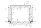
- region R is divided into arrangement
- a rough surface S having a surface roughness rougher than that of the glass plate 2 is provided in at least a part of the non-arrangement region Rb adjacent to the arrangement region Ra.
- the arrangement area Ra is also rectangular.
- the rough surface S is provided in the non-arrangement region Rb adjacent to at least a part of each side of the arrangement region Ra.
- the rough surface S is provided only in a part of the accommodation region R.
- the rough surface S is provided only in the frame-like region including the non-arrangement region Rb adjacent to a part of each side of the arrangement region Ra. Is provided.
- the rough surface S is provided from the non-arrangement region Rb to the arrangement region Ra.
- the rough surface S has a short side portion Sa extending along the short side of each glass plate 2 and a long side portion Sb extending along the long side of each glass plate 2, and the short side The ends of the part Sa and the long side part Sb are connected to each other.
- the rough surface S is provided between the pair of positioning portions 4 that can contact each side of the glass plate 2 in the non-arrangement region Rb.
- the rough surface S is provided in the peripheral part except the periphery of the mounting part 3 in arrangement
- the long side portion Sb is connected in the entire region in the longitudinal direction.
- short side part Sa is not connected between the glass plates 2 arranged in the horizontal direction.
- the surface roughness of the rough surface S can be defined by, for example, the arithmetic average roughness Ra.
- the surface roughness of the rough surface S is preferably 100 nm to 200 nm in terms of arithmetic average roughness Ra.
- the surface roughness of the rough surface S is less than 100 nm in arithmetic mean roughness Ra, the difference between the glass plate 2 and the rough surface S may not be sufficiently obtained in the image data, and the position of the glass plate 2 may not be recognized. There is.
- the surface roughness of the rough surface S exceeds 200 nm in terms of arithmetic average roughness Ra, dust may be generated on the rough surface S during use of the glass plate tray 1.
- the surface roughness of the rough surface S is more preferably 110 nm to 190 nm, and most preferably 115 nm to 185 nm in terms of arithmetic average roughness Ra.
- the surface roughness of the flat surface of the accommodation region R other than the rough surface S is, for example, an arithmetic average roughness Ra of 20 nm to 80 nm. Therefore, the flat surface of the non-arranged region Rb other than the rough surface S can be regarded as a flat surface due to the difference in the level of surface roughness from the rough surface S.
- the area of the rough surface S is preferably 50% or less of the area of the accommodation region R (including the areas of the placement part 3 and the positioning part 4).
- the area of the rough surface S is more preferably 40% or less of the area of the accommodation region R, and most preferably 30% or less of the area of the accommodation region R.
- the difference in surface roughness between the rough surface S and the glass plate 2 is preferably 100 nm to 200 nm in terms of arithmetic average roughness Ra.
- the difference in surface roughness between the rough surface S and the glass plate 2 is less than 100 nm in terms of arithmetic average roughness Ra, the difference between the glass plate 2 and the rough surface S cannot be sufficiently obtained in the image data. The position may not be recognized.
- the difference in surface roughness exceeds 200 nm in arithmetic average roughness Ra, dust may be generated on the rough surface S during use of the glass plate tray 1.
- the difference in surface roughness is more preferably 110 nm to 160 nm, and most preferably 120 nm to 150 nm in terms of arithmetic average roughness Ra.
- the glass plate tray 1 As a manufacturing method of the glass plate tray 1, it is preferable to use a mold in which a blasting process such as sandblasting is performed in advance on a position corresponding to the rough surface S. This is because when the glass plate tray 1 is directly blasted, there is a high possibility of dust generation on the rough surface S during use of the glass plate tray 1.
- the glass plate tray 1 of the present embodiment configured as described above can enjoy the following effects.
- the rough surface S is provided in the non-arrangement region Rb adjacent to the arrangement region Ra, and is provided from the non-arrangement region Rb to the arrangement region Ra.
- the glass plate 2 arrange
- the present invention is not limited to the above embodiment, and various modifications are possible within the scope of the technical idea.
- the glass plate accommodated in a glass plate tray was rectangular shape, square shape may be sufficient and polygonal shape, circular shape, etc. may be sufficient.
Landscapes
- Engineering & Computer Science (AREA)
- Mechanical Engineering (AREA)
- Packaging Frangible Articles (AREA)
Abstract
本発明は、画像データにおいて、ガラス板とその周辺との違いを明確にし、ピックアップ装置におけるガラス板の位置認識のエラーを減少させることを目的とする。 ガラス板トレイ(1)は、複数のガラス板(2)を平置き状態で収容可能な収容領域(R)を備える。収容領域(R)は、ガラス板(2)が配置可能な配置領域(Ra)と、配置領域(Ra)以外の非配置領域(Rb)に区画される。非配置領域(Rb)のうち配置領域(Ra)に隣接する領域の少なくとも一部に、ガラス板(2)より表面粗さが粗い粗面(S)が設けられている。
Description
本発明は、例えばガラス板の搬送や保管等に使用されるガラス板トレイの改良技術に関する。
例えばCCD等の固体撮像素子のカバーガラス等に使用されるガラス板は、トレイに収容されて、搬送や保管等が行なわれる。この用途に使用されるトレイは、通常、複数のガラス板を平置き状態で収容可能である。(例えば特許文献1~3参照)。
ところで、このようなトレイに収容されたガラス板は、トレイから取り出される場合、ピックアップ装置によって自動でピックアップされることが通例である。このピックアップの際には、最初に、ピックアップ装置は、ガラス板とその周辺を撮像手段によって撮像する。次に、ピックアップ装置は、撮像手段で形成される画像データにおけるガラス板と周辺との違いに基づいてガラス板の位置を認識する。そして、ピックアップ装置は、認識したガラス板の位置に基づいてガラス板をピックアップする。
しかしながら、画像データにおいて、ガラス板とその周辺との違いが明確でないことに起因して、ピックアップの際に、ピックアップ装置で、ガラス板の位置認識のエラーが生じる場合があった。
本発明は、上記事情に鑑み、ピックアップ装置におけるガラス板の位置認識のエラーを減少させることを技術的課題とする。
前記課題を解決するために創案された本発明に係るガラス板トレイは、複数のガラス板を平置き状態で収容可能な収容領域を備えたガラス板トレイであって、前記収容領域の少なくとも一部に、画像データにより前記ガラス板とその周辺との違いを認識できる面が設けられていることに特徴づけられる。
この構成では、画像データによりガラス板とその周辺との違いを認識できる面を設けているので、画像データにおけるガラス板とその周辺は区別し易いものになる。また、画像データによりガラス板とその周辺との違いを認識できる面は、ガラス板を収容する収容領域に設けられているので、ガラス板の周辺に配置できる。そのため、画像データにおいて、ガラス板とその周辺との違いを明確にすることができる。従って、ピックアップ装置で、容易にガラス板を位置認識することが可能である。すなわち、本発明によれば、ピックアップ装置におけるガラス板の位置認識のエラーを減少させることが可能になる。なお、画像データによりガラス板とその周辺との違いを認識できる面は、収容領域の少なくとも一部を粗面にしたり、溝を設けたり、着色させたりすることで形成できる。
上記の構成において、前記収容領域の少なくとも一部に、前記ガラス板より表面粗さが粗い粗面が設けられていることに特徴づけられる。
この構成では、粗面の表面粗さはガラス板の表面粗さより粗いので、画像データにおける粗面とガラス板は区別し易いものになる。また、粗面は、ガラス板を収容する収容領域に設けられているので、ガラス板の周辺に配置できる。そのため、画像データにおいて、ガラス板とその周辺との違いを明確にすることができる。従って、ピックアップ装置で、容易にガラス板を位置認識することが可能である。すなわち、本発明によれば、ピックアップ装置におけるガラス板の位置認識のエラーを減少させることが可能になる。
上記の構成において、前記収容領域は、前記ガラス板が配置可能な配置領域と、前記配置領域以外の非配置領域に区画され、前記非配置領域のうち前記配置領域に隣接する領域の少なくとも一部に、前記粗面が設けられていることが好ましい。ここで、配置領域は、ガラス板を配置可能な最大の領域であり、寸法公差等で、平面視でガラス板が配置領域より小さくなる場合もあり得る(以下、同様)。
この構成であれば、粗面が、配置領域に隣接する非配置領域に設けられているので、平面視で、配置領域に配置されたガラス板と、粗面とが略隣接する。そのため、画像データにおいて、ガラス板と粗面との境界が明確となる。従って、ピックアップ装置で、更に容易にガラス板の位置を認識でき、ピックアップ装置におけるガラス板の位置認識のエラーを更に減少させることができる。
上記の構成において、前記配置領域が長方形状であり、前記配置領域の各辺における少なくとも一部に隣接する前記非配置領域に前記粗面が設けられていることが好ましい。
この構成であれば、平面視で、配置領域に配置された長方形状のガラス板の各辺と、粗面とが隣接するので、画像データで、ガラス板の四辺と粗面との境界が明確となる。従って、ピックアップ装置で、長方形状のガラス板の全ての辺の位置認識ができ、これにより、ガラス板の位置認識の精度が向上し、より精度の高いピックアップが可能となる。
上記の構成において、前記配置領域の各辺における少なくとも一部に隣接する前記非配置領域を含む額縁状の領域にのみ前記粗面が設けられていることが好ましい。
この構成であれば、発塵源となり得る粗面を額縁状の領域のみに設けるので、粗面を小面積にすることが可能である。従って、ガラス板トレイの使用中に粗面で発塵する事態を回避することが可能である。
上記の構成において、前記粗面が、前記非配置領域から前記配置領域に亘って設けられていることが好ましい。
この構成であれば、トレイやガラス板の寸法公差等により、ガラス板が配置領域より小さくなったり、ガラス板が配置領域内で偏って配置されたりした場合でも、平面視でガラス板と粗面とが隣接することが可能である。従って、ピックアップ装置で、より確実にガラス板の位置認識をすることができ、ガラス板の位置認識のエラーをより確実に減少させることができる。
以上のように本発明によれば、ピックアップ装置におけるガラス板の位置認識のエラーを減少させることができる。
以下、本発明を実施するための形態について図面に基づき説明する。
図1は、本発明の実施形態に係るガラス板トレイを示す平面図であり、図2は、本発明の実施形態に係るガラス板トレイを示す側面図である。
このガラス板トレイ1は、上下方向に積重可能であり、例えばポリカーボネート、ABS樹脂等の樹脂製である。ガラス板トレイ1は、その全体が略平板状であって、本実施形態では、平面視で長方形状(図1で横方向の辺が長辺)であり、その4隅の1つに方向識別用の面取り部1aが形成されている。
ガラス板トレイ1の上面1bには、その外縁部よりやや中央側に突条部1cが全周に亘って設けられている。上面1bにおける突条部1cより中央側の上面主領域1dは、平面状であり、複数のガラス板2を平置き状態で収容可能な収容領域Rである。収容領域Rには、収容された各ガラス板2の周縁部が載置される載置部3と、該載置部3に載置された各ガラス板2を水平方向に位置決めする位置決め部4が設けられている。
図3に示すように、ガラス板トレイ1の下面1eには、その外縁部に隆起部1fが全周に亘って設けられている。下面1eにおける隆起部1fより中央側の下面主領域1gは、平面状であり、ガラス板トレイ1を積重した時に、各ガラス板2に当接する当接部5が設けられている。下面1eにおける隆起部1fには、ロボットの爪が係合するための凹部1hが所定の位置に複数設けられている。
ガラス板トレイ1を積重した時に、突条部1cの外周に隆起部1fの内周が嵌合し、突条部1cより外縁側の領域に隆起部1fの下面が当接すると共に、下面主領域1gが突条部1cの上面に当接するように構成されている。これにより、積重したガラス板トレイ1が、相互に上下方向と水平方向に位置決めされる。
本実施形態では、ガラス板2は長方形状であり、ガラス板2の大きさは、10mm×20mm以上、好ましくは、20mm×30mm以上、より好ましくは30mm×40mm以上であるが、勿論、これ未満の大きさであってもよい。また、ガラス板2の板厚は、0.4mm~1.0mm、好ましくは0.5mm~0.9mm、より好ましくは0.6mm~0.8mmであるが、これに限定されるものでは無い。
ガラス板2の表面粗さは、例えば、算術平均粗さRaで、10.0nm以下が好ましく、5.0nm以下がより好ましく、2.0nm以下が最も好ましい。なお、算術平均粗さRaの定義は、JIS B 0601:2013に準拠する(以下、同様)。2.0nm以下の算術平均粗さRaのガラス板2は、例えば、オーバーフローダウンドロー法によって製造すれば、研磨を実施せずに得ることができる。
本実施形態では、上面主領域1dに、縦3列×横2列で6枚のガラス板2が、長辺を列の横方向とした状態で配置可能になっている。そして、1枚のガラス板2の4隅の下面が、それぞれ1つの載置部3の上面に載置される。これにより、ガラス板2の下面における載置部3に載置されていない部位が、上面主領域1dに隙間を介して対向する。図4,5に拡大して示すように、本実施形態では、載置部3は、半球形状であるが、これに限定されるものではなく、直方体形状等であってもよい。
1枚のガラス板2の4角に、位置決め部4が当接可能となっている。詳述すれば、ガラス板2の1つの角を構成する一対の端面のそれぞれに、1つの位置決め部4の側面が当接可能となっている。これにより、位置決め部4によってガラス板2が水平方向に位置決めされる。
また、図4,5に拡大して示すように、本実施形態では、位置決め部4は、略直方体形状であり、平面視で、ガラス板2の当接可能な辺に垂直な方向の寸法L1が、ガラス板2の当接可能な辺の方向の寸法L2より大きい。また、位置決め部4において、平面視で長辺に相当する側面は平面状であるが、平面視で短辺に相当する側面が部分円筒面状となっている。位置決め部4の側面と上面の間は丸められている。図示例では、位置決め部4は、平面視での長辺がガラス板2の端面に垂直となるように配置されおり、部分円筒面状の側面がガラス板2の端面に当接可能になっている。
なお、本実施形態では、縦方向に配列されているガラス板2の間で、平面視で長辺の端面に当接可能な位置決め部4が共用されている。つまり、縦方向に配列されているガラス板2の間では、1つの位置決め部4が2枚のガラス板2に当接可能になっている。
また、下面1eの下面主領域1gの当接部5は、ガラス板トレイ1を積重した時に、下側のガラス板トレイ1に収容されたガラス板2の上面に当接する。当接部5は、図4に点線で示すように、ガラス板2の平面視での各辺に沿った方向の中央位置に配置されている。図4,5に拡大して示すように、本実施形態では、当接部5は、半球形状であるが、これに限定されるものではなく、直方体形状等であってもよい。
図6に示すように、ガラス板トレイ1を大気圧下で積重した時に、載置部3がガラス板2の下面に当接すると共に上側のガラス板トレイ1の当接部5がガラス板2の上面に当接する。一方で、位置決め部4の上端面が、上側のガラス板トレイ1の下面1eの下面主領域1gと隙間Gを介して対向する。
この隙間Gの大きさdは、例えば0.02mm~0.18mm、好ましくは0.05mm~0.15mm、更に好ましくは0.08mm~0.12mmであるが、これに限定されるものでは無い。
ガラス板トレイ1は、ある程度の可撓性を有しているので、ガラス板トレイ1を積重した状態で包装して減圧密封した時に、位置決め部4の上端面が、上側のガラス板トレイ1の下面1eの下面主領域1gと接触する。
図1及び図4に示すように、収容領域Rは、ガラス板2が配置可能な配置領域Raと、配置領域Ra以外の非配置領域Rbに区画される。そして、ハッチングで示すように、非配置領域Rbのうち配置領域Raに隣接する領域の少なくとも一部に、ガラス板2より表面粗さが粗い粗面Sが設けられている。
ガラス板2が長方形状であるので、配置領域Raも長方形状である。そして、配置領域Raの各辺における少なくとも一部に隣接する非配置領域Rbに粗面Sが設けられている。粗面Sは、収容領域Rの一部のみに設けられており、本実施形態では、配置領域Raの各辺における一部に隣接する非配置領域Rbを含む額縁状の領域にのみ粗面Sが設けられている。また、粗面Sは、非配置領域Rbから配置領域Raに亘って設けられている。
また、粗面Sは、各ガラス板2の短辺に沿って延在する短辺部Saと、各ガラス板2の長辺に沿って延在する長辺部Sbとを有し、短辺部Saと長辺部Sbは端部同士が接続されている。詳述すれば、粗面Sは、非配置領域Rbにおいては、ガラス板2の各辺に当接可能な一対の位置決め部4の間に設けられている。また、粗面Sは、配置領域Raにおいては、載置部3の周辺を除いた周縁部に設けられており、中央部には設けられていない。また、縦方向に配列されたガラス板2の間では、長辺部Sbが、その長手方向の全域で接続されている。また、横方向に配列されたガラス板2の間では、短辺部Saは接続されていない。
粗面Sの表面粗さについては、例えば、算術平均粗さRaで定義することができる。
粗面Sの表面粗さは、算術平均粗さRaで100nm~200nmであることが好ましい。粗面Sの表面粗さが、算術平均粗さRaで100nm未満の場合、画像データにおいて、ガラス板2と粗面Sの差が十分に得られず、ガラス板2の位置認識ができない可能性がある。粗面Sの表面粗さが、算術平均粗さRaで200nmを超える場合、ガラス板トレイ1の使用中に粗面Sで発塵する可能性がある。この観点から、粗面Sの表面粗さは、算術平均粗さRaで110nm~190nmであることがより好ましく、115nm~185nmであることが最も好ましい。
なお、粗面S以外の収容領域Rの平坦な表面の表面粗さは、例えば、算術平均粗さRaで、20nm~80nmである。従って、粗面S以外の非配置領域Rbの平坦な表面は、粗面Sとの表面粗さのレベルの違いから平面とみなせる。
また、平面視で、粗面Sの面積は、収容領域Rの面積(載置部3と位置決め部4の面積を含む)の50%以下であることが好ましい。粗面Sの面積が収容領域Rの面積の50%を超える場合、ガラス板トレイ1の使用中に粗面Sで発塵する可能性がある。この観点から、粗面Sの面積は、収容領域Rの面積の40%以下であることがより好ましく、収容領域Rの面積の30%以下であることが最も好ましい。
また、粗面Sとガラス板2の表面粗さの差は、算術平均粗さRaで100nm~200nmであることが好ましい。
粗面Sとガラス板2の表面粗さの差が、算術平均粗さRaで100nm未満の場合、画像データにおいて、ガラス板2と粗面Sの差が十分に得られず、ガラス板2の位置認識ができない可能性がある。表面粗さの差が、算術平均粗さRaで200nmを超える場合、ガラス板トレイ1の使用中に粗面Sで発塵する可能性がある。この観点から、表面粗さの差は、算術平均粗さRaで110nm~160nmであることがより好ましく、120nm~150nmであることが最も好ましい。
ガラス板トレイ1の製造方法としては、粗面Sに対応する位置にサンドブラスト等のブラスト処理を予め施した金型を使用して製造することが好ましい。これは、ガラス板トレイ1に直接ブラスト処理を施した場合、ガラス板トレイ1の使用中に粗面Sで発塵する可能性が高いからである。
以上のように構成された本実施形態のガラス板トレイ1では、以下の効果を享受できる。
粗面Sが、配置領域Raに隣接する非配置領域Rbに設けられており、また、非配置領域Rbから配置領域Raに亘って設けられている。これにより、平面視で、配置領域Raに配置されたガラス板2と、粗面Sとが隣接する。そのため、画像データにおいて、ガラス板2と粗面Sとの境界が明確となる。従って、ピックアップ装置で、容易にガラス板2の位置を認識できる。すなわち、本実施形態のガラス板トレイ1によれば、ピックアップ装置におけるガラス板2の位置認識のエラーを減少させることができる。
本発明は、上記実施形態に限定されず、その技術的思想の範囲で様々な変形が可能である。例えば、上記実施形態では、ガラス板トレイに収容されるガラス板は、長方形状であったが、正方形状でもよく、多角形状、円形状等であってもよい。
1 ガラス板トレイ
2 ガラス板
R 収容領域
Ra 配置領域
Rb 非配置領域
S 粗面
2 ガラス板
R 収容領域
Ra 配置領域
Rb 非配置領域
S 粗面
Claims (6)
- 複数のガラス板を平置き状態で収容可能な収容領域を備えたガラス板トレイであって、
前記収容領域の少なくとも一部に、画像データにより前記ガラス板とその周辺との違いを認識できる面が設けられていることを特徴とするガラス板トレイ。 - 前記収容領域の少なくとも一部に、前記ガラス板より表面粗さが粗い粗面が設けられていることを特徴とする請求項1に記載のガラス板トレイ。
- 前記収容領域は、前記ガラス板が配置可能な配置領域と、前記配置領域以外の非配置領域に区画され、
前記非配置領域のうち前記配置領域に隣接する領域の少なくとも一部に、前記粗面が設けられていることを特徴とする請求項2に記載のガラス板トレイ。 - 前記配置領域が長方形状であり、
前記配置領域の各辺における少なくとも一部に隣接する前記非配置領域に前記粗面が設けられていることを特徴とする請求項3に記載のガラス板トレイ。 - 前記配置領域の各辺における少なくとも一部に隣接する前記非配置領域を含む額縁状の領域にのみ前記粗面が設けられていることを特徴とする請求項4に記載のガラス板トレイ。
- 前記粗面が、前記非配置領域から前記配置領域に亘って設けられていることを特徴とする請求項3~5の何れか1項に記載のガラス板トレイ。
Priority Applications (1)
| Application Number | Priority Date | Filing Date | Title |
|---|---|---|---|
| CN201680006204.3A CN107207152B (zh) | 2015-04-28 | 2016-01-27 | 玻璃板托盘 |
Applications Claiming Priority (2)
| Application Number | Priority Date | Filing Date | Title |
|---|---|---|---|
| JP2015091407A JP6575925B2 (ja) | 2015-04-28 | 2015-04-28 | ガラス板トレイ |
| JP2015-091407 | 2015-04-28 |
Publications (1)
| Publication Number | Publication Date |
|---|---|
| WO2016174887A1 true WO2016174887A1 (ja) | 2016-11-03 |
Family
ID=57199177
Family Applications (1)
| Application Number | Title | Priority Date | Filing Date |
|---|---|---|---|
| PCT/JP2016/052367 Ceased WO2016174887A1 (ja) | 2015-04-28 | 2016-01-27 | ガラス板トレイ |
Country Status (3)
| Country | Link |
|---|---|
| JP (1) | JP6575925B2 (ja) |
| CN (1) | CN107207152B (ja) |
| WO (1) | WO2016174887A1 (ja) |
Citations (4)
| Publication number | Priority date | Publication date | Assignee | Title |
|---|---|---|---|---|
| JP2005280751A (ja) * | 2004-03-29 | 2005-10-13 | Kyocera Corp | 透光性部材用搬送トレー |
| JP2010047319A (ja) * | 2008-07-23 | 2010-03-04 | Nippon Electric Glass Co Ltd | 板ガラス収納積層梱包体、及び板状物収納トレイ |
| JP2010243317A (ja) * | 2009-04-06 | 2010-10-28 | Seiko Epson Corp | 物体認識方法 |
| JP2013105778A (ja) * | 2011-11-10 | 2013-05-30 | Shin Etsu Polymer Co Ltd | 電子部品保持具 |
Family Cites Families (1)
| Publication number | Priority date | Publication date | Assignee | Title |
|---|---|---|---|---|
| JP2009184687A (ja) * | 2008-02-04 | 2009-08-20 | Murata Mach Ltd | ワーク搬送用トレイ |
-
2015
- 2015-04-28 JP JP2015091407A patent/JP6575925B2/ja active Active
-
2016
- 2016-01-27 WO PCT/JP2016/052367 patent/WO2016174887A1/ja not_active Ceased
- 2016-01-27 CN CN201680006204.3A patent/CN107207152B/zh active Active
Patent Citations (4)
| Publication number | Priority date | Publication date | Assignee | Title |
|---|---|---|---|---|
| JP2005280751A (ja) * | 2004-03-29 | 2005-10-13 | Kyocera Corp | 透光性部材用搬送トレー |
| JP2010047319A (ja) * | 2008-07-23 | 2010-03-04 | Nippon Electric Glass Co Ltd | 板ガラス収納積層梱包体、及び板状物収納トレイ |
| JP2010243317A (ja) * | 2009-04-06 | 2010-10-28 | Seiko Epson Corp | 物体認識方法 |
| JP2013105778A (ja) * | 2011-11-10 | 2013-05-30 | Shin Etsu Polymer Co Ltd | 電子部品保持具 |
Also Published As
| Publication number | Publication date |
|---|---|
| JP6575925B2 (ja) | 2019-09-18 |
| CN107207152B (zh) | 2019-05-17 |
| JP2016204044A (ja) | 2016-12-08 |
| CN107207152A (zh) | 2017-09-26 |
Similar Documents
| Publication | Publication Date | Title |
|---|---|---|
| JP4360431B2 (ja) | 半導体チップ収容トレイ | |
| KR200464274Y1 (ko) | 기판 적재용 트레이 | |
| CN1076699C (zh) | 盛放部件的托盘 | |
| JP4063805B2 (ja) | 収納トレイおよび収納装置 | |
| JP5470060B2 (ja) | 収納トレイ | |
| JP6575925B2 (ja) | ガラス板トレイ | |
| TWI515158B (zh) | Parts handling carrier | |
| JP6369683B2 (ja) | ガラス板トレイ | |
| KR101632828B1 (ko) | 반도체 칩 트레이 | |
| JP5294701B2 (ja) | トレイ治具 | |
| JP4832568B2 (ja) | 電子部品収納容器 | |
| JP6481760B2 (ja) | 電子部品収納トレイ、複数電子部品収納体、および電子部品取り扱い方法 | |
| JP2001278238A (ja) | 電子部品収納用トレイ | |
| KR101711735B1 (ko) | 반도체 칩 트레이 | |
| KR101658306B1 (ko) | 반도체 칩 트레이 | |
| CN210311274U (zh) | 一种预防擦花板损的线路板转运盘 | |
| KR102603102B1 (ko) | 표시 패널용 트레이 및 트레이 집합체 | |
| KR101035628B1 (ko) | 기판용 트레이 | |
| JP2012012089A (ja) | 電子デバイス用収納容器 | |
| TWI669256B (zh) | 收納用承盤 | |
| JP2009202883A (ja) | レンズユニット収納用トレイ | |
| KR101770461B1 (ko) | 반도체 칩 트레이 | |
| TW202615310A (zh) | 間隔件及捆包體 | |
| JPH07254637A (ja) | 半導体チップトレー | |
| CN101224802A (zh) | 用于光学元件的运输托盘及其中装载的光学元件 |
Legal Events
| Date | Code | Title | Description |
|---|---|---|---|
| 121 | Ep: the epo has been informed by wipo that ep was designated in this application |
Ref document number: 16786164 Country of ref document: EP Kind code of ref document: A1 |
|
| NENP | Non-entry into the national phase |
Ref country code: DE |
|
| 122 | Ep: pct application non-entry in european phase |
Ref document number: 16786164 Country of ref document: EP Kind code of ref document: A1 |