WO2016171201A1 - 切削インサートおよび切削工具 - Google Patents
切削インサートおよび切削工具 Download PDFInfo
- Publication number
- WO2016171201A1 WO2016171201A1 PCT/JP2016/062596 JP2016062596W WO2016171201A1 WO 2016171201 A1 WO2016171201 A1 WO 2016171201A1 JP 2016062596 W JP2016062596 W JP 2016062596W WO 2016171201 A1 WO2016171201 A1 WO 2016171201A1
- Authority
- WO
- WIPO (PCT)
- Prior art keywords
- corner
- cutting insert
- cutting
- angle
- corner portion
- Prior art date
- Legal status (The legal status is an assumption and is not a legal conclusion. Google has not performed a legal analysis and makes no representation as to the accuracy of the status listed.)
- Ceased
Links
Images







Classifications
-
- B—PERFORMING OPERATIONS; TRANSPORTING
- B23—MACHINE TOOLS; METAL-WORKING NOT OTHERWISE PROVIDED FOR
- B23B—TURNING; BORING
- B23B27/00—Tools for turning or boring machines; Tools of a similar kind in general; Accessories therefor
- B23B27/14—Cutting tools of which the bits or tips or cutting inserts are of special material
-
- B—PERFORMING OPERATIONS; TRANSPORTING
- B23—MACHINE TOOLS; METAL-WORKING NOT OTHERWISE PROVIDED FOR
- B23B—TURNING; BORING
- B23B27/00—Tools for turning or boring machines; Tools of a similar kind in general; Accessories therefor
- B23B27/14—Cutting tools of which the bits or tips or cutting inserts are of special material
- B23B27/18—Cutting tools of which the bits or tips or cutting inserts are of special material with cutting bits or tips or cutting inserts rigidly mounted, e.g. by brazing
- B23B27/20—Cutting tools of which the bits or tips or cutting inserts are of special material with cutting bits or tips or cutting inserts rigidly mounted, e.g. by brazing with diamond bits or cutting inserts
Definitions
- the present invention relates to a cutting insert in which a cutting edge member containing an ultra-high pressure sintered body is fixed in a region including a corner portion, and a cutting tool including the cutting insert.
- a cutting tool having a cutting edge portion formed of a so-called ultra-high pressure sintered body is known.
- a conventional cutting tool including an ultra-high pressure sintered body is disclosed in Patent Document 1.
- the cutting edge member is formed of an ultra-high pressure sintered body containing at least one of diamond and cubic boron nitride.
- a rake face is formed on one end face (upper face) of the cutting blade member.
- a clearance surface is formed on the peripheral side surface of the cutting blade member.
- a cutting edge having an arcuate corner cutting edge is formed at the intersection ridge line portion between the rake face and the flank face.
- the base member to which the cutting blade member made of ultra high pressure sintered body is attached is made of, for example, cemented carbide.
- an ultra-high pressure sintered body has lower toughness than a cemented carbide. Therefore, when cutting is performed using a cutting insert that uses an ultra-high-pressure sintered body as the cutting edge material, chips may be sandwiched between the cutting insert and the workpiece, resulting in the periphery of the cutting insert's cutting edge. Chipping and chipping may occur. Such chipping or chipping shortens the tool life.
- An object of the present invention is to suppress or prevent chipping and chipping around a cutting edge in a cutting tool using an ultra-high pressure sintered body as a cutting edge material.
- the cutting insert is provided with a cutting edge at a crossing ridge line portion with the flank, and the cutting insert includes a base portion and a tip nose portion connected to the base portion.
- a cutting blade member is provided at the tip nose portion.
- the cutting edge member includes at least one of cubic boron nitride and diamond.
- the cutting tool of the present invention is a cutting tool provided with the cutting insert of the present invention.
- chipping and chipping around the cutting edge can be suppressed or prevented in the cutting tool using the ultra-high pressure sintered body as the cutting edge material.
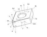
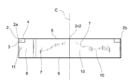
- FIG. 1 is a perspective view of a cutting insert according to the first embodiment.
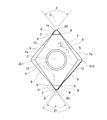
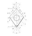
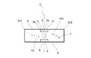
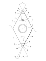
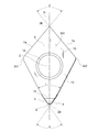
- FIG. 2 is a plan view of the cutting insert of FIG.
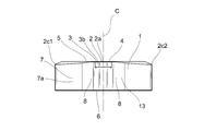
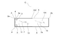
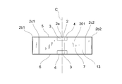
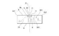
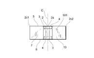
- FIG. 3 is a front view of the cutting insert of FIG.
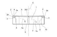
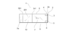
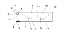
- FIG. 4 is a right side view of the cutting insert of FIG.
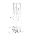
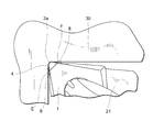
- FIG. 5 is a perspective view of a cutting tool equipped with the cutting insert of FIG. 6 is a partially enlarged plan view of the cutting insert of FIG.
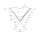
- FIG. 7 is an explanatory diagram of a gap between the cutting tool and the workpiece of FIG.
- FIG. 8 is a perspective view of a cutting insert according to the second embodiment.
- FIG. 9 is a plan view of the cutting insert of FIG.
- FIG. 10 is a front view of the cutting insert of FIG.
- FIG. 11 is a right side view of the cutting insert of FIG.
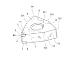
- FIG. 12 is a perspective view of a cutting insert according to the third embodiment.
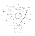
- FIG. 13 is a plan view of the cutting insert of FIG.
- FIG. 14 is a front view of the cutting insert of FIG.
- FIG. 15 is a left side view of the cutting insert of FIG.
- FIG. 16 is a perspective view of a cutting tool equipped with the cutting insert of FIG.
- FIG. 17 is a perspective view of a cutting insert according to the fourth embodiment.
- FIG. 18 is a plan view of the cutting insert of FIG.
- FIG. 19 is a front view of the cutting insert of FIG. 20 is a right side view of the cutting insert of FIG.
- FIG. 21 is a perspective view of a cutting tool equipped with the cutting insert of FIG.
- FIG. 22 is an explanatory diagram of a gap between the cutting tool of FIG.
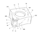
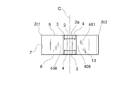
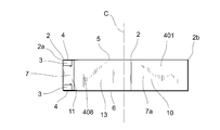
- FIG. 23 is a perspective view of a cutting insert in the fifth embodiment.
- FIG. 24 is a plan view of the cutting insert of FIG.
- FIG. 25 is a front view of the cutting insert of FIG.
- FIG. 26 is a right side view of the cutting insert of FIG.
- FIG. 27 is a perspective view of a cutting insert in the sixth embodiment.
- FIG. 28 is a plan view of the cutting insert of FIG.
- FIG. 29 is a front view of the cutting insert of FIG.
- FIG. 30 is a right side view of the cutting insert of FIG.
- the cutting insert 1 includes two opposing end surfaces 5 and 6 and a peripheral side surface 7 connecting between these end surfaces.
- one end surface 5 shown in FIG. 1 may be referred to as an upper surface
- the other end surface 6 may be referred to as a lower surface.
- the expression which shows the direction and positional relationship in space such as an upper surface
- this is for convenience and intended to define the absolute direction and positional relationship in the space. It is not a thing.
- the cutting insert 1 in this embodiment is formed with an outer shape (contour shape) so as to have a substantially rhomboid plate shape as a basic shape. Therefore, the first end face 5 has a substantially rhombus shape and has four corner portions 2.
- the cutting insert 1 is made of a cemented carbide or the like made of a cutting edge member 3 containing an ultra-high pressure sintered body in a region including the first corner portion 2a among the four corner portions 2 of the first end face 5. Is fixed to the base chip 13.
- the ultra-high pressure sintered body of the cutting insert 1 in this embodiment is a sintered body containing cubic boron nitride.
- the cutting blade member 3 is also fixed to the region including the second corner portion 2b. In addition, the cutting blade member 3 is not arrange
- the base chip 13 has a base 10 including a hole 12 and two tip nose parts 11 connected to the base 10 respectively.
- a cutting blade member 3 is fixed to each tip nose portion 11.
- the first and second corner portions 2a and 2b are formed by fixing the cutting blade member 3 to each of the two tip nose portions 11.
- the 2nd corner part 2b is located in the diagonal of the 1st corner part 2a.
- the cutting blade member 3 is a substantially plate-like member, and has two opposing end surfaces and a peripheral side surface extending therebetween.
- the cutting blade member 3 is disposed on the base chip 13 so that one end surface 3a of the two end surfaces and the peripheral side surface 3b are exposed.
- This one end surface 3a of the cutting blade member 3 may be referred to as an upper surface.
- Part of one end face 3a and peripheral side face 3b exposed of the cutting blade member 3 forms part of the surface of the cutting insert 1. That is, the end surface (upper surface) 3 a of the cutting blade member 3 forms a part of the first end surface (upper surface) 5 of the cutting insert 1, and the peripheral side surface 3 b of the cutting blade member 3 is the peripheral side surface 7 of the cutting insert 1.
- One cutting edge 4 is formed with respect to one cutting edge member 3.
- the flank is formed on the peripheral side surface 7, and the rake face is formed on the first end surface 5. Therefore, the upper surface 3a of the cutting blade member 3 becomes a rake face, and the peripheral side surface 3b becomes a flank face.
- the cutting edge 4 is formed in the intersection ridgeline part of a rake face and a flank face.
- the cutting insert 1 in this embodiment is shown in FIG. 2 (planar surface of the cutting insert 1) as viewed from the direction facing the first end face 5 so that it can be used for both right-handed use and left-handed use. In view), the first corner portion 2a is symmetrical with respect to the bisector D of the first corner portion 2a.
- the bisector D of the first corner portion 2a means a virtual straight line that bisects the outer shape of the first corner portion 2a in plan view. In plan view of the cutting insert 1, the bisector D of the first corner portion 2a is also a bisector of the second corner portion 2b.
- the cutting insert 1 is provided with a hole 12 penetrating the center of each of the two end faces 5 and 6.
- the central axis of the hole 12 intersects the bisector D.
- the cutting insert 1 is detachably attached to the holder 21.
- the cutting tool 20 is a turning tool.
- the cutting insert 1 is mounted on a concave chip seat formed in the holder 21, and the fixing member (pressing member) 22 is fixed to the holder 21 by contacting the upper surface 5 of the cutting insert 1 and the inner surface of the hole 12.
- the fixing member (pressing member) 22 is fixed to the holder 21 by contacting the upper surface 5 of the cutting insert 1 and the inner surface of the hole 12.
- Various known prior art shapes can be applied to a tool body such as a holder.
- the cutting insert 1 in this embodiment has an outer shape so as to have a substantially rhomboid plate shape as a basic shape.
- a substantially rhombic virtual contour shape (basic shape) S of the first end surface (upper surface) 5 is defined in a plan view of FIG.
- a substantially rhombus virtual contour shape can be determined by looking at the cutting insert 1 from the direction facing the second end surface 6.
- the contour line of the virtual contour shape S of the cutting insert 1 is determined along the contour of the base 10 of the cutting insert.
- the virtual contour shape S is determined so that the cutting insert 1 does not protrude from the contour line, and has a number of corner portions that matches the number of corner portions 2 of the first end face 5.
- the apex angle on the acute angle side is about 80 °
- the apex angle on the obtuse angle side is about 100 °.
- corresponds to the apex angle of the acute angle side of the substantially rhombus virtual outline shape S.
- the second corner portion 2b also corresponds to the apex angle on the acute angle side of the substantially rhombic virtual contour shape S, and has the same corner interior angle as the first corner portion 2a. Further, the two corner portions 2c1 and 2c2 related to the base portion 10 correspond to the apex angle on the obtuse angle side of the substantially rhombic virtual contour shape S and have the same corner inner angle.
- the second end surface 6 of the cutting insert 1 is a flat surface facing the first end surface 5.
- the second end surface 6 is a seating surface when the cutting insert 1 is mounted on the cutting tool 10.
- the cutting edge member 3 is not disposed on the second end face 6 side.
- the second corner portion 2b is formed in a shape that is 180-degree rotationally symmetric with the first corner portion 2a with respect to an axis C that is defined so as to pass through the first end surface 5 and the second end surface 6. . In other words, it is formed in a shape that is 180 ° rotationally symmetric with the first corner portion 2a with respect to an axis C that passes through the center of the first end surface 5 and is orthogonal to the first end surface 5.
- the axis C coincides with the central axis of the hole 12.
- the direction of the cutting insert 1 is changed and the second corner portion 2 b is changed to the first corner portion 2 b. It can be used at least twice by replacing the corner portion 2a.
- the first corner portion 2a will be described, and the description of the second corner portion 2b will be omitted unless particularly necessary.
- the cutting edge angle ⁇ of the first corner portion 2a is about 70 °.
- the apex angle of the first corner portion 2a is an angle ⁇ formed by two linear cutting edge portions extending on both sides of the first corner portion 2a.
- the cutting blade member 3 With respect to the cutting blade member 3, the cutting blade 4 extends along the edge of the end surface 3a (intersecting ridge line portion between the end surface 3a and the peripheral side surface 3b) in the plan view of the cutting insert 1 of FIG.
- the cutting edge 4 has a corner (corner cutting edge) 4a defined on the cutting edge member 3, and cutting edge portions 4b and 4c extending on both sides of the corner 4a.
- the cutting edge portions 4b and 4c are linear in FIG.
- the cutting edge portions 4 b and 4 c extend to the edge portion of the end surface 3 a, and are linearly formed on the edge portion of the first end surface 5 in the corner tip portion 1 d in the region beyond the cutting blade member 3.
- the angle formed by these two cutting edge portions 4b and 4c is the corner inner angle of the first corner portion 2a, and is the aforementioned blade edge angle ⁇ .
- the cutting edge angle ⁇ is also referred to as a first corner inner angle.
- a substantially rhombic virtual contour shape (basic shape) S of the first end face (upper surface) 5 is defined in FIG.
- the virtual vertex angle (corner inner angle) of the acute corner corner portion corresponding to the second corner portion 2b is defined as an angle ⁇
- the virtual vertex angle corresponding to the first corner portion 2a is defined as the angle.
- ⁇ 2 is also referred to as a second corner internal angle ⁇
- the angle ⁇ 2 is also referred to as a third corner internal angle ⁇ 2.
- the angle ⁇ 2 in the first corner portion 2a of the virtual contour shape S is the same angle as the angle ⁇ in the second corner portion 2b.
- the second corner inner angle ⁇ and the third corner inner angle ⁇ 2 are both about 80 °. That is, the cutting edge angle ⁇ is smaller than the second and third corner inner angles ⁇ and ⁇ 2, and the difference between the second and third corner inner angles ⁇ and ⁇ 2 and the cutting edge angle ⁇ is about 10 °. Therefore, as apparent from FIGS. 2 and 6, the cutting insert 1 is formed to be narrower than the virtual contour shape S in each of the first and second corner portions 2a and 2b. .
- the base 10 of the base chip 13 has a contour shape that matches the virtual contour shape S in FIG.
- the base portion 10 has two corner portions 2c1 and 2c2 corresponding to two obtuse apex angles.
- the two side portions 9 extending from each of the two corner portions 2c1 and 2c2 toward the first corner portion 2a are linear, and are referred to as straight portions 9 herein.
- the angle formed by the two straight portions 9 toward the first corner portion 2a is the third corner inner angle ⁇ 2
- the angle formed by the two straight portions toward the second corner portion 2b is the first angle.
- the corner internal angle ⁇ is 2.
- the base 10 of the base chip 13 is formed to have a wider angle than the tip nose portion 11 including the cutting edge member 3 that forms the cutting edge 4.
- the base 10 defines a contact surface 7a of the peripheral side surface 7 that contacts the side wall surface of the chip seat. That is, in the plan view, each straight line portion 9 is arranged on the outermost side in the contour shape. The virtual straight line extending each straight line portion 9 is in contact with the contour shape without intersecting. Two contact surfaces 7a are provided so as to sandwich the corner portion with respect to the second corner portion 2b. Therefore, two contact surfaces 7a are provided so as to sandwich the corner portion with respect to the first corner portion 2a.
- the contact surface 7 a is connected to a concave portion (concave region) 8.
- the concave portion 8 extends from the first end surface 5 to the second end surface 6, and the width in the circumferential direction does not change between the first end surface 5 and the second end surface 6.
- the concave portion 8 is formed in a portion of the peripheral side surface 7 between the first corner portion 2a and one obtuse corner portion 2c1 located adjacent to the first corner portion 2a.
- the blade member 3 is provided close to the first corner portion 2a so as to include the peripheral side surface 3b.
- a recess 8 is also formed in a portion of the peripheral side surface 7 between the first corner portion 2a and the other obtuse corner portion 2c2 located adjacent to the first corner portion 2a.
- the concave portion 8 is also a concave side surface that connects the peripheral side surface corresponding to the first corner portion 2a and the contact surface 7a closest to the first corner portion 2a.
- the shape of the portion of the peripheral side surface 7 that does not contact the side wall surface of the chip seat (that is, the shape of the portion excluding the peripheral side surface of the tip nose portion 11 from the recess 8) of the peripheral side surface 7 excluding the tip nose portion 11 is You may be made into such a shape.
- the peripheral side surface 7 can be provided with a portion that does not contact the side wall surface of the chip seat as the concave portion 8, and the cutting edge 4 or the like can be formed in the concave portion 8.
- the cutting edge portions 4b and 4c are connected to both sides of the corner cutting edge 4a, so that two recesses 8 are provided with respect to the first corner portion 2a.
- the cutting insert 1 is also formed with a recess 8 around the second corner portion 2b so that the cutting edge 4 and the like are also formed in a portion that does not contact the side wall surface of the chip seat.
- a cutting edge 4 of 70 ° is provided. That is, the recessed part 8 is formed in the both sides of the 1st and 2nd corner parts 2a and 2b, and a total of four are formed.
- the cutting insert 1 is mounted on the tip seat of the tool body 21 so that the cutting edge 4 of the first corner portion 2a becomes a working cutting edge
- the second end surface that is, the lower surface 6 is placed so as to contact the bottom surface of the chip seat.
- the two contact surfaces 7a closer to the second corner portion 2b than the two obtuse corner portions 2c1 and 2c2 are brought into contact with the side wall surfaces of the corresponding chip seats.
- the side wall surface of the chip seat extends so as to intersect the bottom surface at a substantially right angle.
- the cutting insert 1 is fixed by the fixing member 22.
- the cutting tool 1 with the cutting insert 1 fixed to the tool body 21 is advanced with respect to the rotating workpiece 30 and used for cutting the workpiece 30.
- the cutting insert 1 in this embodiment has a virtual apex angle ⁇ of about 80 °, so that it has a substantially rhomboid plate shape with an apex angle of 80 ° on the acute angle side standardized by JIS B 4121 and ISO 3364. It can be attached to a holder using an insert.
- the second corner internal angle ⁇ is the smallest corner internal angle among the maximum corner internal angles of all the corners 2 determined along the contour shape of the base portion 10.
- the third corner inner angle ⁇ 2 is also the same angle as the second corner inner angle ⁇ , and is the smallest corner inner angle among the maximum corner inner angles of all the corners 2 determined along the contour shape of the base 10. It is.
- the corner portions 2c1 and 2c2 are obtuse angles, and each has an obtuse maximum corner inner angle. Therefore, when the cutting edge 4 of the first corner portion 2a is the working cutting edge, the maximum corner inner angles of the three corner portions 2b, 2c1 and 2c2 other than the first corner portion are all of the first corner portion 2a. It is larger than the first corner interior angle ⁇ . Therefore, it is possible to use the cutting insert 1 in which the tip nose portion 11 of the first corner 4a of the working cutting edge 4 is narrower than the normal cutting insert used in the tool holder 21.
- the holder 21 of the cutting tool 20 exemplified in this embodiment is an example of a holder that has been conventionally used.
- a lathe tool using a cutting insert having a cutting edge angle of 80 ° is often used because it can perform both outer diameter processing and end surface processing with high efficiency.
- the cutting insert 1 according to this embodiment is mounted on a widely used holder 21 so that both outer diameter processing and end surface processing can be performed in the same manner as in the case of a substantially diamond-shaped cutting insert having a cutting edge angle of 80 °. It can be cut efficiently.
- the cutting insert 1 can use the holder 21 used frequently by exchanging only the cutting insert.
- the machining program etc. which were used with the conventional cutting tool can also be utilized as it is.
- the positions of the first and second corner portions 2a and 2b with respect to the holder 21 are substantially the same as the positions of the corner portions of the substantially rhombic plate-like cutting insert having an acute angle apex angle of 80 °. .
- the 1st and 2nd corner parts 2a and 2b when mounting
- the cutting insert does not need to match the position of the first corner portion 2a with the position of the corner portion of the substantially rhomboid cutting insert having an acute angle apex angle of 80 °. That is, in the case where the holder is not limited to a conventionally used holder, the position of the first corner portion 2a in the cutting insert alone may be any position. In that case, it is preferable to use a holder that matches the shape of the cutting insert.
- the edge angle (first corner inner angle) ⁇ of the first corner portion 2a determined in the tip nose portion 11 is larger than the maximum corner inner angle ⁇ of the second corner 2b which is the smallest other than the first corner portion 2a. Is also small. Therefore, the periphery of the first corner portion 2 a of the cutting edge member 3 of the tip nose portion 11 is formed at a corner inner angle that is narrower than the size of a normal cutting insert attached to the holder 21. . Therefore, according to the cutting insert 1, the clearance gap between the workpiece 30 and the cutting blade 4 periphery can be enlarged. Therefore, it is possible to prevent chips from being caught around the cutting edge, suppress chipping and chipping, and extend the tool life of the cutting insert.
- the edge angle (first corner inner angle) ⁇ of the first corner portion 2a is about 70 °.
- the virtual vertex angle (second corner inner angle) ⁇ of the second corner portion 2b is about 80 °. That is, as shown in FIG. 6, the edge angle ⁇ is only an angle ⁇ (( ⁇ ) / 2) on one side with respect to the side (imaginary line) of the rhomboid virtual contour shape S whose acute angle side is the virtual apex angle ⁇ . It has been made smaller.
- this angle is referred to as a fourth angle ⁇ .
- the virtual apex angle ⁇ is set to about 80 °
- the fourth angle ⁇ is set to about 5 °
- the cutting tool 10 having the recess 8 formed in the peripheral side surface 7 of the cutting insert 1 and having cubic boron nitride as the cutting edge member 3 generally has a small cutting depth, so that E shown in FIG.
- the gap between the workpiece 30 and the cutting insert 1 is increased by the recessed area, that is, the recessed portion 8 in the portion and the F portion.
- the gap between the cutting blade member of the ultra-high pressure sintered body and the workpiece 30 it is preferable to increase the gap between the cutting blade member of the ultra-high pressure sintered body and the workpiece 30.
- the gap in the vicinity of the boundary between the cemented carbide portion and the cutting blade member 3 with respect to the side (virtual line) of the rhombic virtual contour shape S is preferably in the range of 0.03 mm or more and 0.60 mm or less.
- the portion of the cutting edge 4 involved in the cutting process hardly changes the contour shape as compared with the cutting edge of the conventional diamond-shaped cutting insert having a cutting edge angle of 80 °.
- the fourth angle ⁇ is 1 ° or more and 9 ° or less in order to satisfy the conflicting requirements of increasing the gap between the portions not involved in cutting and not changing the contour shape of the cutting edge 4 involved in cutting.
- the range of is preferable. That is, when the concave portions 8 are provided on both sides of the first corner portion 2a as in this embodiment, the difference between the virtual vertex angle ⁇ and the blade edge angle ⁇ is preferably in the range of 2 ° or more and 18 ° or less.
- the cutting edge angle ⁇ is preferably in the range of 62 ° or more and 78 ° or less.
- the concave portion 8 does not necessarily have to be provided on both sides of the first and second corner portions 2a and 2b. Moreover, even when the recessed part 8 is provided in both sides, it is not limited to a mirror-symmetric shape. Therefore, including the case where the concave portion 8 is provided only on one side, the difference between the virtual vertex angle ⁇ and the blade edge angle ⁇ is preferably in the range of 1 ° or more and 18 ° or less.
- the fourth angle ⁇ is less than 1 °, the gap hardly increases with respect to the sides of the rhombic virtual contour shape S having an apex angle of 80 °, and therefore, the effect of suppressing or preventing chipping or the like is obtained. I can't get it.
- the fourth angle ⁇ exceeds 9 °, there may be a problem that the roughness of the finished surface of the workpiece 30 is lowered. In this case, in order to maintain the roughness of the finished surface, it is necessary to lower the feed and the like among the cutting conditions.
- the virtual apex angle ⁇ of about 80 ° is preferably in the range of 79 ° or more and 81 ° or less.
- the fourth angle ⁇ is more preferably in the range of 3 ° or more and 7 ° or less. That is, the difference between the virtual vertex angle ⁇ and the blade edge angle ⁇ is more preferably in the range of 3 ° or more and 14 ° or less.
- the cutting edge 4 is honed. That is, the cutting edge 4 has honing.
- the honing is provided from the corner cutting edge 4a of the first corner portion 2a along the cutting edge portions 4b and 4c having a cutting edge angle ⁇ . Therefore, the corner cutting edge 4a and the cutting edge portions 4b and 4c have a constant honing width and shape.
- the cutting insert 1 in this embodiment has a honing extending parallel to the cutting edge portions 4 b and 4 c, and is separated from the first corner portion 2 a along the extending direction of the cutting edge 4. As it does, it has the width expansion part where the width of honing becomes wide. When the width of honing is increased, the occurrence of chipping and defects can be further suppressed.
- the cutting insert 1 is not limited to that the honing is applied along the portion of the cutting edge 4 having a cutting edge angle ⁇ .
- the honing shape in which the honing width increases as the distance from the first corner portion 2a along the cutting edge 4 increases even when the honing shape is generally applied to a roughly diamond-shaped cutting insert having a cutting edge angle of 80 °. Or the effect which prevents a defect
- the flank of the cutting insert 1 is placed on the holder 21 so as to give an appropriate flank angle, and the width of the honing becomes wide and the dimension in the height direction of the honing becomes large. 4 is lowered in a side view and retracted in a plan view, and a gap between the workpiece 30 and the cutting edge 4 is increased.
- the cutting insert 1 in this embodiment is provided with a cutting edge 4 portion having a cutting edge angle ⁇ , so that the width of the honing of the portion acting as the cutting edge 4 is kept constant and the cutting resistance is kept low, while the width is increased.
- Various known conventional techniques can be applied to the shape and size of the honing of the cutting edge 4 involved in cutting.
- the cutting insert 1 may be formed so as to be inclined so that the cutting edge 4 approaches the second end face 6 as it is separated from the first corner portion 2a.
- the cutting edge 4 is inclined in this way in the side view, the cutting edge 4 is lowered in the side view due to the clearance angle and retracted in the plan view, and the gap between the workpiece 30 and the cutting edge 4 increases.
- the inclination of the cutting edge 4 may be inclined by giving a positive rake angle to the rake face.
- FIGS. 1 and 2nd Embodiment a cutting insert 101 according to a second embodiment of the present invention will be described with reference to FIGS.
- the same components as those of the cutting insert 1 in the first embodiment are denoted by the same reference numerals, and the description thereof is omitted.
- the main difference with the cutting insert 1 of 1st Embodiment of the cutting insert 101 which concerns on 2nd Embodiment is demonstrated.
- the cutting insert 101 in this embodiment includes, on the first end surface 5, a first corner portion 2a having an apex angle of about 70 °, and a second corner portion 2b having an apex angle of about 80 ° as the maximum corner internal angle. It is formed in the substantially square plate shape provided with. The first corner portion 2a and the second corner portion 2b are arranged diagonally. In addition, the corner internal angle in planar view of each of the remaining corner parts 2c1 and 2c2 is an obtuse angle.
- the peripheral side surface 7 corresponding to two sides (see FIG. 9) sandwiching the second corner portion 2b is configured to be mounted on the same holder 21 as the cutting insert 1 in the first embodiment.
- the contact surface 7a of the peripheral side surface 7 corresponding to the two sides sandwiching the second corner portion 2b is a substantially rhomboid plate shape whose apex angle on the acute angle side standardized by JIS B 4121 or ISO 3364 is 80 °. It is formed so that it can be attached to a holder using a cutting insert.
- a cutting edge member 3 containing an ultra-high pressure sintered body is fixed to a region including the first corner portion 2a, and a cutting edge 4 is formed. Therefore, the cutting edge angle ⁇ is about 70 °, and the apex angle (second corner inner angle) ⁇ of the second corner portion 2b is about 80 °.
- the cutting edge member 3 is fixed to the first corner portion 2a, and the cutting edge member 3 is arranged in the remaining three corner portions 2b, 2c1, 2c2. It has not been.
- the cutting insert 101 is an axis parallel to the first end face 5 and passing through the center of the first and second end faces 5 and 6, and an axis parallel to the bisector D of the first corner portion 2a ( It is formed in a shape that is 180 ° rotationally symmetric with respect to the central axis C of the hole 12. In other words, the cutting insert 101 is formed in the same shape on the front and back of the cutting insert 101 in plan view. That is, the cutting edge member 3 is also fixed to the second end face 6 to form the cutting edge 4.
- the cutting edge 4 is honed.
- the width of the honing is constant along the cutting edge 4. However, it is not limited to this.
- the base chip 13 has a base 10 including a hole 12 and a tip nose portion 11 connected to the base 10.
- a and a length dimension B from the center to the second corner portion 2b are determined. Since the cutting insert 101 in this embodiment has the hole 12 at substantially the center, the length dimensions A and B coincide with the dimension from the central axis C of the hole 12. It is preferable that the length dimensions A and B of the cutting insert 101 are substantially equal.
- the cutting insert of this embodiment is applied to the corner portion of the basic shape of a substantially rhomboid plate having an acute angle of 80 ° when mounted on the cutting tool 10.
- the position of the first corner portion 2a 101 is substantially the same position. If it is in such a position, when the cutting insert 101 is mounted on the holder 21 that is often used, the first corner portion 2a and the peripheral cutting edge 4 are greatly protruded to the outside of the holder 21. It is possible to prevent the fixation from becoming unstable and the cutting blade 4 from protruding from the holder 21 due to being too small. That is, the positions of the first corner portion 2a and the cutting edge 4 are arranged at substantially the same position as the corner portion and the cutting edge position of a generally used 80 ° rhombus-shaped cutting insert. For this reason, the holder 21 used frequently can be utilized by exchanging only the cutting insert.
- the length dimension A and the length dimension B are not required to be exactly the same dimension. It is required only to substantially match the position of the corner part and the cutting edge of a generally used 80 ° rhombus-shaped cutting insert with the length dimension A, and within the intended range, the length dimension A Is allowed to be slightly different from the length dimension B. This difference can be adjusted by aligning the origin when mounted on the machine tool.
- the difference between the length dimension A and the length dimension B is preferably in the range of 1 mm or less.
- the difference between the length dimension A and the length dimension B is more preferably 0.2 mm or less.
- the second corner portion 2b is not provided with a roundness (corner radius), but is not limited thereto.
- the corner radius of the second corner portion 2b may be provided with an arbitrary roundness such as 0.8 mm.
- the length dimension B is preferably based on the length dimension when the corner radius is 0.8 mm.
- a cutting insert 201 according to the third embodiment of the present invention will be described with reference to FIGS.
- the same components as those of the cutting inserts 1 and 101 in the first and second embodiments are denoted by the same reference numerals, and the description thereof is omitted.
- the main differences between the cutting insert 201 in the third embodiment and the cutting inserts 1 and 101 in the first and second embodiments will be described.
- the cutting insert 201 in this embodiment includes a first corner portion 2a having an apex angle of about 70 ° on the first end face 5, two corner portions 2b1 and 2b2 having an apex angle of about 80 °, and the three corners. It is formed in a substantially hexagonal plate shape including three obtuse corner portions 2c1, 2c2, and 2c3 arranged between the portions. As shown in FIG. 13, in plan view, the cutting insert 201 in this embodiment has a shape symmetrical with respect to the bisector D of the first corner portion 2a.
- the second corner portion 2b1 is assumed to be the corner portion 2 arranged at the upper left in FIG.
- the third corner portion 2c1 is the corner portion 2 existing between the first corner portion 2a and the second corner portion 2b1.
- a cutting edge member 3 containing an ultra-high pressure sintered body is fixed to an area including the first corner portion 2a, and a cutting edge 4 is formed. Therefore, the cutting edge angle (first corner inner angle) ⁇ is about 70 °, the apex angle (second corner inner angle) ⁇ of the second corner portion 2b is about 80 °, and the third corner portion 2c1 The apex angle is about 165 °. That is, the apex angle of the third corner portion 2c1 is larger than the cutting edge angle ⁇ and the apex angle ⁇ of the second corner portion.
- the apex angle of the corner portion 2c3 is about 160 °.
- the corner portion 2b2 has an apex angle of about 80 °, which is the same as that of the second corner portion 2b1, and the corner portion 2c2 has an apex angle of about 165 °, which is the same as that of the third corner portion 2c1.
- the cutting edge member 3 is fixed to the first corner portion 2a, and the remaining five corner portions 2b1, 2b2, 2c1, 2c2, and 2c3 are cut.
- the blade member 3 is not disposed.
- the cutting insert 201 is an axis parallel to the first end surface 5 and passing through the center of the first and second end surfaces 5 and 6, and an axis parallel to the bisector D of the first corner portion 2a ( It is formed in a shape that is 180 ° rotationally symmetric with respect to the central axis C of the hole 12.
- the cutting insert 101 is formed in the same shape on the front and back of the cutting insert 101 in plan view. That is, the cutting edge member 3 is also fixed to the second end face 6 to form the cutting edge 4.
- honing is omitted and not drawn. Honing may have any shape and width, and various conventional techniques are applied.
- the base chip 13 has a base 10 including a hole 12 and a tip nose portion 11 connected to the base 10.
- the cutting insert 201 is provided with a hole 12 that passes through substantially the center of each of the two end faces 5 and 6.
- a cutting insert 201 is detachably attached to a holder 221.
- This cutting tool 220 is a turning tool.
- the cutting insert 201 is placed on a concave chip seat formed in the holder 221, and the fixing member is fixed to the holder 221 by contacting the upper surface 5 of the cutting insert 201 and the inner surface of the hole 12.
- the same fixing member as the fixing member 22 of the cutting tool 20 in the first embodiment can be used as the fixing member.
- the peripheral side surface 7 including the second corner portion 2b of the cutting insert 201 is formed so that it can be attached to a holder using a substantially hexagonal plate-shaped cutting insert standardized by JIS B 4121 or ISO 3364. Yes. That is, the apex angle ⁇ of the second corner portion 2b is formed at about 80 °, the apex angle of the corner portion 2c3 is formed at about 160 °, and with respect to the bisector D of the first corner portion 2a. Since it has a line-symmetric shape, it can be mounted on a holder using a substantially hexagonal plate-shaped cutting insert with a cutting edge angle of 80 °, which is standardized by JIS B 4121 and ISO3364.
- the holder 221 of the cutting tool 220 illustrated in this embodiment is an example of a widely used holder.
- a lathe tool using a cutting insert having a cutting edge angle of 80 ° is often used because it can perform both outer diameter processing and end surface processing with high efficiency.
- the cutting insert 201 of the present embodiment is mounted on a widely used holder 221 to perform both outer diameter processing and end surface processing in the same manner as a substantially hexagonal plate-shaped cutting insert having a cutting edge angle of 80 °. Cutting can be performed with high efficiency.
- the cutting insert 201 of this embodiment can use the holder 221 that is often used by replacing only the cutting insert. Moreover, the machining program etc. which were used with the conventional cutting tool can also be utilized as it is.
- the length dimension B from the center of the 1st end surface 5 in the dimension on the bisector of the 2nd corner part 2b to the 2nd corner part 2b is defined. Since the cutting insert 201 in this embodiment has the hole 12 at substantially the center, the length dimensions A and B coincide with the dimension from the central axis C of the hole 12.
- the cutting insert 201 preferably has substantially equal length dimensions A and B.
- the corner of the cutting insert in the conventional basic shape of a substantially hexagonal plate shape is the first of the cutting insert 201 of the present embodiment.
- the position of one corner portion 2a can be aligned at substantially the same position.
- the positions of the first corner portion 2a and the cutting edge 4 are arranged at substantially the same position as the corner portion and the cutting edge position of a hexagonal plate-shaped cutting insert having a cutting edge angle of 80 ° which is widely used.
- the length dimension A and the length dimension B are not required to be exactly the same dimension. In the hexagonal basic shape, it is only required to substantially match the position of the corner and cutting edge of the cutting insert with the length dimension A. Within the intended range, the length dimension A is slightly different from the length dimension B. Different dimensions are allowed. This difference can be adjusted by aligning the origin when mounted on the machine tool.
- the cutting insert 201 of this embodiment is provided with a roundness (corner radius) of about 0.8 mm in the second corner portion 2b. However, it is not limited to this. The roundness of the second corner portion 2b may be an arbitrary corner radius.
- the length dimension B is preferably based on the length dimension when the corner radius is 0.8 mm.
- a cutting insert 301 according to a fourth embodiment of the present invention will be described with reference to FIGS.
- the same components as those of the cutting inserts 1, 101, 201 in the first to third embodiments are denoted by the same reference numerals, and the description thereof is omitted.
- the main differences of the cutting insert 301 in the fourth embodiment of the present invention from the cutting inserts 1, 101, 201 in the first to third embodiments will be described.
- the cutting insert 301 in this embodiment includes, on the first end surface 5, first and second corner portions 2 a and 2 b having an acute angle side virtual apex angle of about 55 °, and an obtuse angle side. It is formed in a substantially rhomboid plate shape including two corner portions 2c1 and 2c2.
- the cutting blade member 3 containing an ultra-high pressure sintered body is fixed to the base chip 13 in a region including the first corner portion 2 a among the four corner portions 2 of the first end surface 5.
- a cutting edge 4 is formed.
- the cutting blade member 3 is also fixed to the region including the second corner portion 2b, and the cutting blade 4 is formed.
- the cutting insert 301 is self-contained so as to be compatible with right-hand use, and has a shape that is asymmetric with respect to the bisector of the first corner portion 2a in plan view. That is, based on FIG. 18, a recess 8 is formed only on the right side of the periphery of the first corner portion 2 a that is the lower corner portion 2.
- the base chip 13 has a base portion 10 including a hole 12 and two tip nose portions 11 connected to the base portion 10.
- the cutting insert 301 includes a hole 12 penetrating the center of each of the two end faces 5 and 6.
- a cutting insert 301 is detachably attached to a holder 321.
- This cutting tool 320 is a turning tool.
- the cutting insert 301 is placed on a concave chip seat formed in the holder 321, and the fixing member is fixed to the holder 321 by contacting the upper surface 5 of the cutting insert 301 and the inner surface of the hole 12.
- the same fixing member as the fixing member 22 of the cutting tool 20 in the first embodiment can be used as the fixing member.
- the second end surface 6 of the cutting insert 301 is a flat surface facing the first end surface 5.
- each cutting blade member 3 is fixed to the first and second corner portions 2a and 2b on the first end face 5 side.
- the cutting blade member 3 is fixed to the two corner portions 2a and 2b on the substantially rhombus acute angle side, and is not disposed on the remaining two corner portions 2c1 and 2c2 on the obtuse angle side. Further, the cutting edge member 3 is not disposed on the second end face 6 side.
- the second corner portion 2 b is formed in a shape that is 180 ° rotationally symmetric with the first corner portion 2 a with respect to an axis C that passes through the center of the first end surface 5 and is orthogonal to the first end surface 5.
- the second corner portion 2 b is formed in a shape that is 180 ° rotationally symmetric with the first corner portion 2 a with respect to the central axis C of the hole 12.
- a cutting edge angle ⁇ when the angle formed by the two linear cutting edge portions 4b and 4c extending on both sides of the corner cutting edge 4a of the first corner portion 2a in the plan view is defined as a cutting edge angle ⁇ ,
- the edge angle ⁇ of the corner portion 2a is about 50 °.
- an angle (maximum corner internal angle) formed by two sides extending on both sides of the second corner portion 2b in the substantially rhombic virtual contour shape S is defined as a virtual vertex angle (second corner internal angle) ⁇ .
- the virtual apex angle ⁇ is about 55 °. That is, the difference between the virtual vertex angle ⁇ and the blade edge angle ⁇ is about 5 °.
- the fourth angle ⁇ is also about 5 °.
- the first corner portion 2a and the second corner portion 2b are arranged diagonally.
- the virtual apex angle ⁇ is also an angle formed by the two linear portions 9 arranged on both sides of the second corner portion 2b in plan view. These linear portions 9 correspond to the contact surface 7a of the peripheral side surface 7 that contacts the side wall surface of the chip seat. That is, the virtual apex angle ⁇ corresponds to an angle substantially formed by the two contact surfaces 7a with the side wall surface of the chip seat.
- Each straight line portion 9 is arranged on the outermost side in the contour shape. That is, the virtual straight line extending each straight line portion 9 is in contact with the contour shape without intersecting.
- abut the side wall surface of a chip seat among the surrounding side surfaces 7 may be made into any shape.
- the peripheral side surface 7 can be provided with a portion that does not contact the side wall surface of the chip seat as the concave portion 8, and the cutting edge 4 or the like can be formed in the concave portion 8.
- a recess 8 is formed around the second corner portion 2b so that the cutting edge 4 and the like are also formed in a portion that does not contact the side wall surface of the chip seat, and the cutting edge is formed.
- a cutting edge 4 having an angle ⁇ of about 50 ° is provided. That is, one recess 8 is formed around each of the first and second corner portions 2a and 2b.
- the concave portion 8 is formed only on one side of each of the first and second corner portions 2a and 2b, and a total of two concave portions 8 are formed.
- the cutting insert 301 of this embodiment has a virtual apex angle ⁇ of about 55 °, so that it has a substantially rhomboid plate shape with an apex angle on the acute angle side standardized by JIS B 4121 or ISO 3364 of 55 °. It can be attached to a holder using an insert.
- the holder 321 of the cutting tool 320 exemplified in this embodiment is an example of a holder that has been conventionally used.
- a lathe tool using a cutting insert having a cutting edge angle of 55 ° is often used because it is suitable for profile processing and the like.
- the cutting insert 301 in this embodiment can be cut in the same manner as the cutting tool having a substantially rhomboid plate shape with a cutting edge angle of 55 ° by being mounted on a widely used holder 321.
- the cutting insert 301 can use the holder 321 used frequently by exchanging only the cutting insert.
- the machining program etc. which were used with the conventional cutting tool can also be utilized as it is.
- the positions of the first and second corner portions 2a and 2b with respect to the holder 321 are substantially the same as the positions of the corner portions of the cutting insert in the basic rhombus plate-shaped basic shape S having an acute angle apex angle of 55 °. It is preferable.
- the first and second corner portions 2a and 2b are mounted when the cutting insert 301 is mounted on a commonly used general holder 321. It is prevented that 2a, 2b and the peripheral cutting edge 4 are protruded largely to the outside of the holder 321, so that the fixing becomes unstable, and the cutting edge 4 does not protrude from the holder 321 because it is too small.
- the cutting edge angle (first corner inner angle) ⁇ of the first corner portion 2a is about 50 °.
- the virtual vertex angle (second corner inner angle) ⁇ of the second corner portion 2b is about 55 °. That is, the edge angle ⁇ is made smaller by about 5 ° with respect to the side of the rhomboid virtual contour shape S whose acute angle side is the virtual apex angle ⁇ . For this reason, as shown in the explanatory diagram of FIG. 22, when cutting a workpiece 30 having a flange shape or the like, the portion around the cutting edge 4 that is not involved in the cutting as the cutting edge 4 is on the acute angle side.
- the edge angle is arranged away from the workpiece 30. That is, the cutting tool 320 having one concave portion 8 formed on the peripheral side surface 7 of the cutting insert 301 and using cubic boron nitride as the cutting blade member 3 generally has a small cutting depth, and therefore, FIG. In the G section shown, the gap between the workpiece 30 and the cutting insert 301 is enlarged by the recess 8. Since a gap (G portion) between the workpiece 30 and a portion not involved in cutting around the cutting edge 4 is increased, chips and the like are prevented from being caught.
- the cutting edge 4 on the side where the concave portion 8 is not formed does not need the concave portion 8 because the gap with the workpiece 30 is originally large.
- the concave portions 8 may be formed on both sides of the first corner portion 2a. The size and arrangement position of the recess 8 can be changed in a timely manner according to the cutting edge angle of the holder to be applied, the shape of the workpiece 30, the cutting conditions, and the like.
- the difference between the cutting edge angle ⁇ and the virtual apex angle ⁇ of the cutting insert 301 in this embodiment is preferably in the range of 1 ° or more and 9 ° or less.
- the difference between the cutting edge angle ⁇ and the virtual apex angle ⁇ is more preferably in the range of 3 ° or more and 7 ° or less.
- honing is omitted and not drawn. Honing may have any shape and width, and various conventional techniques can be applied.
- a cutting insert 401 according to the fifth embodiment of the present invention will be described with reference to FIGS.
- the same components as those of the cutting inserts 1, 101, 201, 301 in the first to fourth embodiments are denoted by the same reference numerals, and the description thereof is omitted.
- the main differences between the cutting insert 401 in the fifth embodiment and the cutting inserts 1, 101, 201, 301 in the first to fourth embodiments will be described.
- the cutting insert 401 in this embodiment is an example in which the cutting insert 101 in the second embodiment is deformed so that a recess 408 is formed.
- the recess 408 of the cutting insert 401 of this embodiment is different from the recess 8 of the cutting insert 1 in the first embodiment in the position and shape to be formed.
- the recessed portion 408 in this embodiment is formed at a position that is separated from the first corner portion 2 a and is also separated from the cutting blade member 3.
- Two concave portions 408 are formed symmetrically with respect to the bisector D of the first corner portion 2a.
- the cutting insert 401 includes a portion having a fifth angle ⁇ due to the formation of the recess 408.
- the fifth angle ⁇ is about 55 °.
- the edge angle ⁇ of the first corner portion 2a is about 70 °. That is, the recess 408 is formed so that the fourth angle ⁇ is smaller than the blade edge angle ⁇ .
- the concave portion 408 does not directly increase the gap between the cutting blade member 3 (the periphery of the cutting blade 4) and the workpiece 30.
- the concave portion 408 further improves the chip discharging performance by increasing the gap between the base tip 13 of the cutting insert 401 and the workpiece 30, and indirectly causes chipping and chipping around the cutting edge 4. Suppress.
- the base chip 13 has a base 10 including a hole 12 and a tip nose portion 11 connected to the base 10.
- the cutting insert 401 is formed on the first end surface 5 in a substantially rectangular plate shape having a first corner portion 2a having an apex angle of about 70 ° and a second corner portion 2b having an apex angle of about 80 °. Yes.
- the first corner portion 2a and the second corner portion 2b are arranged diagonally.
- the contact surface 7a of the peripheral side surface 7 corresponding to the two sides sandwiching the second corner portion 2b is configured to be mounted on the same holder 21 as the cutting insert 1 in the first embodiment.
- the contact surface 7a of the peripheral side surface 7 corresponding to the two sides sandwiching the second corner portion 2b is a substantially rhomboid plate shape whose apex angle on the acute angle side standardized by JIS B 4121 or ISO 3364 is 80 °. It is formed so that it can be attached to a holder using a cutting insert.
- a cutting edge member 3 containing an ultra-high pressure sintered body is fixed to a region including the first corner portion 2a, and a cutting edge 4 is formed. Therefore, the cutting edge angle (first corner inner angle) ⁇ is about 70 °, and the apex angle (second corner inner angle) ⁇ of the second corner portion 2b is about 80 °.
- the cutting edge member 3 On the first end face 5 side of the cutting insert 401 in this embodiment, the cutting edge member 3 is fixed to the first corner portion 2a, and the cutting edge member 3 is disposed at the remaining three corner portions 2b, 2c1, 2c2. It has not been.
- the cutting insert 401 is an axis parallel to the first end surface 5 and passing through the center of the first and second end surfaces 5 and 6, and an axis parallel to the bisector D of the first corner portion 2a ( It is formed in a shape that is 180 ° rotationally symmetric with respect to the central axis C of the hole 12. That is, the cutting edge member 3 is also fixed to the second end face 6 to form the cutting edge 4.
- the cutting edge 4 is honed.
- the width of the honing is constant along the cutting edge 4.
- the present invention is not limited to this, and various known conventional techniques can be applied to honing.
- the same components as those of the cutting inserts 1, 101, 201, 301, 401 in the first to fifth embodiments are denoted by the same reference numerals, and the description thereof will be given. Omitted.
- the main differences between the cutting insert 501 in the sixth embodiment and the cutting inserts 1, 101, 201, 301, 401 in the first to fifth embodiments will be described.
- the cutting insert 501 in this embodiment is an example in which the cutting insert 101 in the second embodiment is deformed so as to have a portion where the fifth angle ⁇ is formed. Is also similar. As shown in the plan view of FIG. 28, in a plan view, the cutting insert 501 has a portion having a fifth angle ⁇ , and the fifth angle ⁇ is about 55 °. The edge angle ⁇ of the first corner portion 2a is about 70 °. That is, the clearance between the cutting insert 501 and the workpiece 30 is increased by making the fifth angle ⁇ smaller than the cutting edge angle ⁇ . The portion having the fifth angle ⁇ does not directly increase the gap between the cutting edge member 3 (the periphery of the cutting edge 4) and the workpiece 30.
- the base chip 13 has a base 10 including a hole 12 and a tip nose portion 11 connected to the base 10.
- the cutting insert 501 is formed on the first end surface 5 in a substantially rectangular plate shape having a first corner portion 2a having an apex angle of about 70 ° and a second corner portion 2b having an apex angle of about 80 °. Yes.
- the first corner portion 2a and the second corner portion 2b are arranged diagonally.
- the contact surface 7a of the peripheral side surface 7 corresponding to the two sides sandwiching the second corner portion 2b is configured to be mounted on the same holder 21 as the cutting insert 1 in the first embodiment.
- the contact surface 7a of the peripheral side surface 7 corresponding to the two sides sandwiching the second corner portion 2b is a substantially rhomboid plate shape whose apex angle on the acute angle side standardized by JIS B 4121 or ISO 3364 is 80 °. It is formed so that it can be attached to a holder using a cutting insert.
- the cutting edge member 3 containing the ultra-high pressure sintered body is fixed to the region including the first corner portion 2a, and the cutting edge 4 is formed. Therefore, the cutting edge angle (first corner inner angle) ⁇ is about 70 °, and the apex angle (second corner inner angle) ⁇ of the second corner portion 2b is about 80 °.
- the cutting insert 401 is an axis parallel to the first end surface 5 and passing through the center of the first and second end surfaces 5 and 6, and an axis parallel to the bisector D of the first corner portion 2a ( It is formed in a shape that is 180 ° rotationally symmetric with respect to the central axis C of the hole 12. That is, the cutting edge member 3 is also fixed to the second end face 6 to form the cutting edge 4.
- the cutting edge 4 is honed.
- the width of the honing is constant along the cutting edge 4.
- the present invention is not limited to this, and various known conventional techniques can be applied to honing.
- the cutting insert of the present invention may have any form as long as it is a cutting insert to which a cutting blade member of an ultra-high pressure sintered body is fixed.
- a known fixing method such as brazing can be applied.
- the cutting insert has a substantially polygonal plate shape.
- wear with the cutting insert standardized by JISB4121 and ISO3364 is preferable.
- the cutting edge member 3 is fixed only on the first end face 5 side, and the cutting edge 4 is formed.
- the cutting blade member 3 may be fixed and the cutting blade 4 may be formed.
- the cutting insert 1 in the first embodiment has a substantially rhomboid plate shape, the cutting insert 1 may have a substantially hexagonal plate shape with a virtual apex angle ⁇ of 80 °. In that case, the three cutting blade members 3 and the cutting blade 4 can be arranged on the first end face 5.
- the cutting edges 4 can be formed in six corner portions 2 (tip nose portions 11) in total.
- the virtual apex angle ⁇ can be set to 60 °, and a cutting insert having a basic shape of a substantially equilateral triangular plate shape can be obtained.
- the basic shape is a substantially equilateral triangular plate shape
- the cutting edge angle ⁇ is preferably in the range of 42 ° or more and 58 ° or less
- the virtual apex angle ⁇ is preferably in the range of 59 ° or more and 61 ° or less.
- the cutting insert 1 can also have a basic shape of a substantially rhomboid plate with a virtual apex angle ⁇ of 55 ° or 35 °.
- the cutting inserts 101 and 201 in the second and third embodiments can also have a basic shape such as a substantially rhomboid plate shape or a substantially equilateral triangular plate shape having different apex angles ⁇ of the second corner portion.
- the cutting edge member 3 and the cutting edge 4 may be formed only on the first end face 5, and the second end face 6 may be a flat face.
- the cutting insert may be asymmetrical with respect to the bisector of the first corner portion 2a.
- the gap is increased only on one side from the basic shapes of a substantially rhomboid plate shape, a substantially hexagonal plate shape, and a substantially triangular plate shape.
- the recess 8 may be formed only on one side.
- you may further have the part of 5th angle (epsilon) smaller than the blade edge angle (alpha) like the cutting inserts 401 and 501 in 5th and 6th embodiment.
- a recess may be further formed in the base tip spaced from the cutting blade member 3.
- the material of the cutting edge member of the cutting insert of the present invention preferably contains at least one of cubic boron nitride and diamond. That is, the cutting edge and the tool material around the cutting edge are coated with a coating film by PVD or CVD on the surface of the sintered body containing cubic boron nitride or the sintered body containing cubic boron nitride. It is preferable to select from among those having sintered materials containing diamond or diamond.
- the cutting insert of the present invention is mounted on a cutting tool, and further, the cutting tool is mounted on a machine tool, so that it can be used for cutting a steel material or the like. It is applied to lathe tools and rotary cutting tools, and there are almost no restrictions on the applicable cutting tools. Although only the cutting insert attached to the tool for lathe has been described in the embodiment, the present invention is not limited to this. It can also be applied to cutting inserts used for rotary cutting tools.
- the cutting insert and the cutting tool of the present invention are not limited to the embodiment described above, and various changes and additions can be made without departing from the gist of the present invention.
- a chip breaker may be formed around the cutting edge.
- a finishing blade portion such as a wiper blade may be provided on the cutting blade portion.
Landscapes
- Engineering & Computer Science (AREA)
- Mechanical Engineering (AREA)
- Milling Processes (AREA)
- Cutting Tools, Boring Holders, And Turrets (AREA)
Abstract
チッピングや欠損の発生を抑制する切削インサートおよび切削工具を提供する。本発明の切削インサートは、対向する2つの端面と、周側面(7)と、を有し、2つの端面のうちの略多角形の第1の端面(5)と周側面との交差稜線部に切れ刃(4)を備える切削インサート(1)であって、切削インサートは、基部(10)と、基部につながる先端ノーズ部(11)とを含む。先端ノーズ部に、切れ刃部材(3)が設けられる。切れ刃部材は、立方晶窒化ほう素およびダイヤモンドの少なくとも一方を含む。第1の端面に対向する方向から切削インサートをみたとき、先端ノーズ部の第1のコーナ部(2a)は第1のコーナ内角αを有し、基部の輪郭に沿って定められる最大コーナ内角が最小である第2のコーナ部(2b)は、第2のコーナ内角βを有し、第1のコーナ内角αは第2のコーナ内角βよりも小さい。
Description
本発明は、コーナ部を含む領域に、超高圧焼結体を含有する切れ刃部材が固着された切削インサート、およびその切削インサートを備える切削工具に関する。
従来、切れ刃部分をいわゆる超高圧焼結体で形成した切削工具が知られている。従来の超高圧焼結体を備える切削工具には、特許文献1に示すものがある。特許文献1の切削工具では、ダイヤモンドおよび立方晶窒化硼素の少なくとも一方を含有する超高圧焼結体で、切れ刃部材が形成されている。切れ刃部材の一方の端面(上面)にはすくい面が形成されている。切れ刃部材の周側面には逃げ面が形成されている。すくい面と逃げ面との交差稜線部に、円弧状のコーナ切れ刃を有する切れ刃が形成されている。
超高圧焼結体製の切れ刃部材が取り付けられるベース部材は例えば超硬合金から作製される。一般に、超硬合金に比べて超高圧焼結体は靱性が低い。したがって、超高圧焼結体を切れ刃の材料に用いた切削インサートを用いて切削加工を行う場合、切削インサートと被加工物との間に切りくずが挟まることなどにより、切削インサートの切れ刃周辺にチッピングや欠損が発生する場合がある。このようなチッピングや欠損は、工具寿命を短くする。
本発明の目的は、超高圧焼結体を切れ刃の材料に用いた切削工具において、切れ刃周辺のチッピングや欠損を抑制ないしは防止することにある。
本発明の一態様によれば、対向する2つの端面と、端面間に延在する周側面と、を有し、2つの端面のうちの略多角形の第1の端面のすくい面と周側面の逃げ面との交差稜線部に切れ刃を備える切削インサートであって、切削インサートは、基部と、基部につながる先端ノーズ部とを含む。先端ノーズ部に、切れ刃部材が設けられる。切れ刃部材は、立方晶窒化ほう素およびダイヤモンドの少なくとも一方を含む。第1の端面に対向する方向から切削インサートをみたとき、先端ノーズ部において定められる第1のコーナ部は第1のコーナ内角αを有し、第1の端面に対向する方向から切削インサートをみたとき、第1のコーナ部以外の第1の端面の全コーナ部のうちで基部の輪郭に沿って定められる最大コーナ内角が最小である第2のコーナ部は、第2のコーナ内角βを有し、第1のコーナ内角αは第2のコーナ内角βよりも小さい。
本発明の切削工具は、本発明の切削インサートを備える切削工具である。
上記構成を有する本発明の一態様によれば、超高圧焼結体を切れ刃の材料に用いた切削工具において、切れ刃周辺のチッピングや欠損を抑制ないしは防止することができる。
本発明を適用した切削インサートの実施形態について、図面を参照しながら説明する。図1から図4に示すように、第1の実施形態における切削インサート1は、2つの対向する端面5、6と、これらの端面の間をつなぐ周側面7とを備える。なお、図1において表されている一方の端面5を上面と称し、他方の端面6を下面と称することがある。なお、上面など空間内の向きや位置関係を示す表現を本明細書において用いているが、これは便宜上のものであって、空間内の絶対的な向きや位置関係を規定することを企図したものではない。
この実施形態における切削インサート1は、略菱形板状を基本形状とするように、外郭形状(輪郭形状)が形成されている。したがって、第1の端面5は、略菱形形状を有し、4つのコーナ部2を有する。切削インサート1は、第1の端面5の4つのコーナ部2のうち、第1のコーナ部2aを含む領域に、超高圧焼結体を含有する切れ刃部材3が、超硬合金などを材料とするベースチップ13に固着されている。この実施形態における切削インサート1の超高圧焼結体は、立方晶窒化ほう素を含有する焼結体とされている。この実施形態における切削インサート1は、第2のコーナ部2bを含む領域にも、切れ刃部材3が固着されている。なお、残りの2つのコーナ部2c1、2c2には、切れ刃部材3が配置されていない。
ベースチップ13は、穴12を含む基部10と、この基部10にそれぞれがつながる2つの先端ノーズ部11とを有する。各先端ノーズ部11には、切れ刃部材3が固着されるように構成されている。2つの先端ノーズ部11の各々に切れ刃部材3が固着されることで、第1および第2のコーナ部2a、2bが形成されている。なお、第2のコーナ部2bは、第1のコーナ部2aの対角に位置する。
切れ刃部材3は、略板状の部材であり、2つの対向する端面と、これらの間に延在する周側面とを有する。切れ刃部材3は、2つの端面のうちの一方の端面3aと、周側面3bとが露出するように、ベースチップ13に配置される。切れ刃部材3のこの一方の端面3aを上面と称し得る。切れ刃部材3の露出する一方の端面3aおよび周側面3bの一部は、切削インサート1の表面の一部を形成している。すなわち、切れ刃部材3の端面(上面)3aは、切削インサート1の第1の端面(上面)5の一部を形成し、切れ刃部材3の周側面3bは、切削インサート1の周側面7の一部を形成している。1つの切れ刃部材3に関して、1つの切れ刃4が形成されている。逃げ面は、周側面7に形成され、すくい面は、第1の端面5に形成されている。したがって、切れ刃部材3の上面3aはすくい面になり、周側面3bは逃げ面となる。切れ刃4は、すくい面と逃げ面との交差稜線部に形成されている。この実施形態における切削インサート1は、右勝手での使用と左勝手での使用とのどちらにも対応できるように、第1の端面5に対向する方向からみた図2において(切削インサート1の平面視において)、第1のコーナ部2aの2等分線Dに対して線対称な形状とされている。なお、第1のコーナ部2aの2等分線Dとは、平面視において、第1のコーナ部2aの外郭形状を2等分する仮想直線のことを意味する。切削インサート1の平面視において、第1のコーナ部2aの2等分線Dは、第2のコーナ部2bの2等分線でもある。
切削インサート1は、2つの端面5、6のそれぞれの中央を貫通する穴12を備えている。穴12の中心軸線は、2等分線Dと交差する。図5に示すように、この実施形態における切削工具20では、切削インサート1がホルダ21に着脱自在に装着されている。切削工具20は、旋盤加工用のバイトである。切削インサート1は、ホルダ21に形成された凹状のチップ座に載置され、固定部材(押さえ部材)22が切削インサート1の上面5および穴12の内面に当接することで、ホルダ21に固定される。しかし、これに限定されない。ホルダなどの工具ボデーは、既知の様々な従来技術の形状が適用できる。
前述のとおり、この実施形態における切削インサート1は、略菱形板状を基本形状とするように、外郭形状が形成されている。第1端面(上面)5の略菱形の仮想輪郭形状(基本形状)Sは、図2の平面視において定められる。第2の端面(下面)6に関しても、第1の端面5と同様に、第2の端面6に対向する方向から切削インサート1をみて、略菱形の仮想輪郭形状を定められる。ただし、切削インサート1の仮想輪郭形状Sの輪郭線は、切削インサートの基部10の輪郭に沿って定められる。この仮想輪郭形状Sは、その輪郭線から切削インサート1がはみ出さないように定められ、かつ、第1の端面5のコーナ部2の数に一致する数のコーナ部を有する。第1の端面5の略菱形の仮想輪郭形状Sにおいて、鋭角側の頂角は約80°とされ、鈍角側の頂角は約100°とされている。先端ノーズ部11に関する第1のコーナ部2aは、略菱形の仮想輪郭形状Sの鋭角側の頂角に対応する。第2のコーナ部2bも、略菱形の仮想輪郭形状Sの鋭角側の頂角に対応し、第1のコーナ部2aと同じコーナ内角を有する。また、基部10に関する2つのコーナ部2c1、2c2は、略菱形の仮想輪郭形状Sの鈍角側の頂角に対応し、互いに同じコーナ内角を有する。
切削インサート1の第2の端面6は、第1の端面5と対向する平坦面とされている。第2の端面6は、切削インサート1が切削工具10に装着されるときの着座面とされる。この実施形態における切削インサート1は、第2の端面6側に切れ刃部材3が配置されていない。第2のコーナ部2bは、第1の端面5および第2の端面6を通過するように定められる軸線Cに対して、第1のコーナ部2aと180°回転対称な形状に形成されている。別の表現をすると、第1の端面5の中央をとおり第1の端面5と直交する軸線Cに対して、第1のコーナ部2aと180°回転対称な形状に形成されている。この実施形態における切削インサート1は、穴12の中心軸線に軸線Cが一致している。この切削インサート1は、第1のコーナ部2aを使用することによって第1のコーナ部2aの周辺に摩耗などが生じた場合、切削インサート1の向きを変えて第2のコーナ部2bを第1のコーナ部2aと入れ替えることで、少なくとも2回の使用ができる。以降は説明を簡略にするため、第1のコーナ部2aに関して説明し、特に必要な場合を除いて、第2のコーナ部2bについての説明は省略する。
図2に示すように、平面視において、第1のコーナ部2aの頂角を刃先角αと定めると、第1のコーナ部2aの刃先角αは、約70°とされている。なお、第1のコーナ部2aの頂角とは、第1のコーナ部2aの両側に延びる直線状の2つの切れ刃部分のなす角αのことである。
ここで、切れ刃部材3についてさらに説明する。切れ刃部材3に関して、図2の切削インサート1の平面視において、その端面3aの縁部(端面3aと周側面3bとの交差稜線部)に沿って切れ刃4が延在する。切れ刃4は、切れ刃部材3に定められるコーナ(コーナ切れ刃)4aと、このコーナ4aの両側に延びる切れ刃部分4b、4cとを有する。切れ刃部分4b、4cは、図2において、直線状である。また、切れ刃部分4b、4cは、図2において、端面3aの縁部に延在し、切れ刃部材3を超えた領域のコーナ先端部1dにおける第1の端面5の縁部に直線状に滑らかにつながる。図2において、これら2つの切れ刃部分4b、4cのなす角が、第1のコーナ部2aのコーナ内角であり、前述の刃先角αである。刃先角αは、第1のコーナ内角とも呼称される。
前述のとおり、図2において、第1の端面(上面)5の略菱形の仮想輪郭形状(基本形状)Sが定められる。仮想輪郭形状Sにおける、第2のコーナ部2bに対応する鋭角の仮想コーナ部の仮想頂角(コーナ内角)を、ここで角度βとし、第1のコーナ部2aに対応する仮想頂角を角度β2とする。角度βは、第2のコーナ内角βとも呼称され、角度β2は、第3のコーナ内角β2とも呼称される。仮想輪郭形状Sの、第1のコーナ部2aにおける角度β2は、第2のコーナ部2bにおける角度βと同じ角度である。第2のコーナ内角βおよび第3のコーナ内角β2は、いずれも約80°とされている。すなわち、刃先角αは第2および第3のコーナ内角β、β2よりも小さく、第2および第3のコーナ内角β、β2と刃先角αとの差は、約10°とされている。したがって、図2および図6から明らかなように、切削インサート1は、第1および第2のコーナ部2a、2bのそれぞれにおいて、仮想輪郭形状Sよりも、幅狭になるように形成されている。ベースチップ13の基部10は、図2において仮想輪郭形状Sに一致する輪郭形状を有する。基部10には、2つの鈍角の頂角に対応する2つのコーナ部2c1、2c2がある。これら2つのコーナ部2c1、2c2のそれぞれから第1のコーナ部2aに向けて延在する2つの辺部9は直線状であり、ここでは直線部9と呼称する。図2において第1のコーナ部2aに向けての2つの直線部9がなす角が第3のコーナ内角β2であり、第2のコーナ部2bに向けての2つの直線部がなす角が第2のコーナ内角βである。このように、ベースチップ13の基部10は、切れ刃4を形成する切れ刃部材3を含む先端ノーズ部11よりも幅広の角度を有するように形成されている。
基部10は、チップ座の側壁面と当接する周側面7の当接面7aを定める。すなわち平面視において、各々の直線部9は、輪郭形状の中で最も外方に配置されている。各々の直線部9を延長する仮想直線は、輪郭形状と交差せずに接する。当接面7aは、第2のコーナ部2bに関してコーナ部を挟むようにして2つ設けられている。したがって、当接面7aは、第1のコーナ部2aに関してコーナ部を挟むようにして2つ設けられている。当接面7aは、凹部(凹領域)8と接続している。凹部8は、第1の端面5から第2の端面6にまで延在し、第1の端面5から第2の端面6の間でその周方向の幅は変化しない。図2において、凹部8は、第1のコーナ部2aとこの第1のコーナ部2aの隣りに位置する一方の鈍角のコーナ部2c1との間の周側面7の部分に形成され、特に、切れ刃部材3における周側面3bを含むように第1のコーナ部2a寄りに設けられている。同様に、第1のコーナ部2aとこの第1のコーナ部2aの隣りに位置する他方の鈍角のコーナ部2c2との間の周側面7の部分にも、凹部8が形成されている。凹部8は、第1のコーナ部2aに対応する周側面と、この第1のコーナ部2aに最も近い当接面7aとをつなぐ凹状側面でもある。なお、先端ノーズ部11を除いて、周側面7のうち、チップ座の側壁面と当接しない部分の形状(つまり凹部8から先端ノーズ部11の周側面を除いた部分の形状)は、どのような形状とされても構わない。逆に言えば、周側面7には、チップ座の側壁面と当接させない部分を凹部8として設けることができ、その凹部8にも切れ刃4などを形成することができる。この実施形態における切削インサート1は、コーナ切れ刃4aの両側に切れ刃部分4b、4cがつながるので、第1のコーナ部2aに関して2つの凹部8が設けられる。切削インサート1は、チップ座の側壁面と当接しない部分にも切れ刃4などが形成されるように、第2のコーナ部2bの周辺にも、凹部8が形成され、刃先角αが約70°の切れ刃4を備えている。すなわち凹部8は、第1および第2のコーナ部2a、2bの両側に形成され、合計4つ形成されている。
次に、本実施形態の切削インサートおよび切削工具の作用および効果について説明する。ここでは、第1のコーナ部2aの切れ刃4が作用切れ刃となるように工具ボデー21のチップ座に切削インサート1が装着された場合について説明する。この場合、第2の端面つまり下面6がチップ座の底面と当接するように載置される。そして、図2において2つの鈍角のコーナ部2c1、2c2よりも第2のコーナ部2b寄りの2つの当接面7aが、それぞれ、対応するチップ座の側壁面に当接させられる。チップ座の側壁面は、底面と略直角に交差するように延在する。そして、その状態で固定部材22により、切削インサート1は固定される。このように工具ボデー21に切削インサート1が固定されたバイトは、回転する被加工物30に対して進められて、被加工物30の切削加工に用いられる。
この実施形態における切削インサート1は、仮想頂角βが約80°に形成されているため、JIS B 4121やISO3364で規格化されている鋭角側の頂角が80°の略菱形板状の切削インサートを用いるホルダへ装着することができる。第2のコーナ内角βは、基部10の輪郭形状に沿って定められる全コーナ2の最大コーナ内角のうち、最少のコーナ内角である。ただし、前述のとおり、第3のコーナ内角β2も、第2のコーナ内角βと同じ角度であり、基部10の輪郭形状に沿って定められる全コーナ2の最大コーナ内角のうち、最少のコーナ内角である。そして、コーナ部2c1、2c2は鈍角であり、それぞれ鈍角の最大コーナ内角を有する。したがって、第1のコーナ部2aの切れ刃4が作用切れ刃とされるとき、第1のコーナ部以外の3つのコーナ部2b、2c1、2c2の最大コーナ内角は全て第1のコーナ部2aの第1のコーナ内角αよりも大きい。よって、工具ホルダ21で用いられる通常の切削インサートと比して、作用切れ刃4の第1のコーナ4aの先端ノーズ部11が幅狭な切削インサート1を使用することができる。この実施形態で例示した切削工具20のホルダ21は、従来から多く用いられているホルダの一例である。刃先角が80°の切削インサートを用いる旋盤用のバイトは、外径加工と端面加工との両方を高能率に切削加工することができるため、多く用いられている。この実施形態の切削インサート1は、多く用いられているホルダ21に装着することで、刃先角が80°の略菱形板状の切削インサートと同様に、外径加工と端面加工との両方を高能率に切削加工することができる。切削インサート1は、切削インサートだけを交換することで、多く用いられているホルダ21が利用できる。また、従来の切削工具で用いられた加工プログラムなども、そのまま利用できる。ホルダ21に対する第1および第2のコーナ部2a、2bの位置は、鋭角側の頂角が80°の略菱形板状の切削インサートのコーナ部の位置と、ほぼ同じ位置にされることが好ましい。このように第1および第2のコーナ部2a、2bの位置が設定されると、多く用いられているホルダ21に切削インサート1を装着するときに、第1および第2のコーナ部2a、2bおよびその周辺の切れ刃4が、ホルダ21の外側に大きく突き出されて固定が不安定になることや、小さすぎてホルダ21から切れ刃4が突出しないことが防止される。ただし、切削インサートは、第1のコーナ部2aの位置を、鋭角側の頂角が80°の略菱形板状の切削インサートのコーナ部の位置と合わせなくても構わない。すなわち、従来から多く用いられているホルダに限定しない場合などは、切削インサート単体での第1のコーナ部2aの位置は、どのような位置とされても構わない。その場合は、切削インサートの形状に合わせたホルダが用いられることが好ましい。
前述のとおり、先端ノーズ部11において定められる第1のコーナ部2aの刃先角(第1のコーナ内角)αは第1のコーナ部2a以外で最小の第2のコーナ2bの最大コーナ内角βよりも小さい。それゆえ、先端ノーズ部11の切れ刃部材3における第1のコーナ部2aの周辺は、このホルダ21に取り付けられる通常の切削インサートの大きさに比して幅狭のコーナ内角に形成されている。したがって、切削インサート1によれば、被加工物30と切れ刃4周辺との隙間を大きくできる。そのため、切れ刃周辺に切りくずが挟まることを防止し、チッピングや欠損の発生を抑制することができ、切削インサートの工具寿命を延長することができる。
前述のとおり、この実施形態における切削インサート1は、第1のコーナ部2aの刃先角(第1のコーナ内角)αが約70°とされている。また第2のコーナ部2bの仮想頂角(第2のコーナ内角)βは約80°とされている。すなわち図6に示すように、鋭角側が仮想頂角βの菱形の仮想輪郭形状Sの辺(仮想線)に対して、刃先角αは、片側の角度γ((β-α)/2)だけ小さくされている。ここでは、この角度を第4の角度γと呼ぶ。この実施形態の切削インサートでは、仮想頂角βが約80°とされ、第4の角度γが約5°とされ、第1のコーナ部2aの両側で約10°小さくされている。このため、図7の説明図に示すように、フランジ形状などを有する被加工物30を切削加工するときなどに、切れ刃4として切削加工に関与しない切れ刃4周辺の部分(例えば凹部8)は、鋭角側の刃先角が80°の菱形の仮想輪郭形状Sの辺と比較して、被加工物30から離れて配置されるようになる。すなわち、切削インサート1の周側面7に凹部8が形成されていて、なおかつ立方晶窒化ほう素を切れ刃部材3とする切削工具10は、一般に切削条件の切込みが小さいので、図7に示すE部およびF部で、くぼんだ領域つまり凹部8によって被加工物30と切削インサート1との隙間が大きくされる。
本発明者の実験によって、超高圧焼結体を切れ刃の材料に用いた切削インサートについて、切れ刃周辺がチッピングまたは欠損する原因の1つが、切りくずが切削インサートと被加工物30との間に挟まることであることが解明された。チッピングや欠損は、超硬合金のベースチップの部分よりも超高圧焼結体の切れ刃部材3の部分で発生しやすい。超高圧焼結体は、超硬合金などと比較して靱性が低く、チッピングや欠損が発生しやすいため、超硬合金などを基本として規格化された外郭形状(輪郭形状)では、超高圧焼結体で問題が発生する場合があることが解明された。したがって、超高圧焼結体の切れ刃部材と、被加工物30との隙間を大きくすることが好ましい。具体的には、平面視において、ベースチップ13である超硬合金の部分と、切れ刃部材3との、境界部付近の被加工物30との隙間を大きくすることが好ましい。菱形の仮想輪郭形状Sの辺(仮想線)に対して、超硬合金の部分と切れ刃部材3との境界部付近の隙間は、0.03mm以上、なおかつ0.60mm以下の範囲が好ましい。本実施形態の切削インサートは、被加工物30と切れ刃4周辺の切削に関与しない部分との隙間(E部またはF部)が大きくなるため、切りくずなどが挟み込まれることが防止される。したがって、切削インサート1の切れ刃4周辺でのチッピングや欠損の発生をさらに抑制し、工具寿命を延長できる。
一方で、切削加工に関与する切れ刃4の部分は、従来の80°の刃先角を有する略菱形の切削インサートの切れ刃と比較して、ほとんど輪郭形状を変えないことが好ましい。切削に関与しない部分の隙間を大きくすることと、切削に関与する切れ刃4の輪郭形状を変えないことの相反する要求を満たすため、第4の角度γは、1°以上、なおかつ9°以下の範囲が好ましい。すなわち、この実施形態のように第1のコーナ部2aの両側に凹部8を設ける場合、仮想頂角βと刃先角αとの差は、2°以上、なおかつ18°以下の範囲が好ましい。別の表現をすると、頂角が80°の菱形の仮想輪郭形状Sのとき、刃先角αは、62°以上、なおかつ78°以下の範囲とされることが好ましい。ただし凹部8は、必ずしも第1および第2のコーナ部2a、2bの両側に設けられなくても構わない。また両側に凹部8が設けられる場合でも、鏡面対称な形状に限定されない。したがって、片側だけに凹部8が設けられる場合などを含めて、仮想頂角βと刃先角αとの差は、1°以上、なおかつ18°以下の範囲が好ましい。第4の角度γが1°未満のときは、頂角が80°の菱形の仮想輪郭形状Sの辺に対して、隙間がほとんど増えないため、切りくずの挟み込みなどを抑制もしくは防止する効果が得られない。一方、第4の角度γが9°を超えると、被加工物30の仕上げ面のあらさが低下するなどの不具合が生じる場合がある。この場合、仕上げ面のあらさを保つには、切削条件のうち、送りなどを下げる必要性が生じる。なお、仮想頂角βが約80°とは、79°以上、なおかつ81°以下の範囲が好ましい。第4の角度γは、3°以上、なおかつ7°以下の範囲がさらに好ましい。すなわち、仮想頂角βと刃先角αとの差は、3°以上、なおかつ14°以下の範囲がさらに好ましい。切削インサート1は、これらの角度に形成されると、チッピングや欠損の発生が抑制され、工具寿命が延長される効果が増大される。
この実施形態における切削インサート1は、切れ刃4にホーニングが付されている。すなわち、切れ刃4はホーニングを有する。ホーニングは、第1のコーナ部2aのコーナ切れ刃4aから刃先角αの切れ刃部分4b、4cに沿って設けられている。したがって、コーナ切れ刃4aおよび切れ刃部分4b、4cは、ホーニングの幅および形状が一定とされている。図1から図4に示すように、この実施形態における切削インサート1は、切れ刃部分4b、4cと平行にホーニングが延長され、切れ刃4の延びる方向に沿って第1のコーナ部2aから離間するにつれ、ホーニングの幅が広くなる幅拡大部分を備える。ホーニングの幅が広くされると、さらにチッピングや欠損の発生を抑制できる。
切削インサート1は、ホーニングが刃先角αの切れ刃4の部分に沿って付されることに限定されない。切れ刃4に沿って第1のコーナ部2aから離間するにつれ、ホーニングの幅が広くなるホーニング形状は、通常に80°の刃先角を有する略菱形の切削インサートなどに付された場合でも、チッピングまたは欠損を防止する効果が得られる。これは、ホーニングの幅が広くなることによる効果と、ホーニングが広くなることで、切れ刃4の部分と被加工物30との間の隙間を増やす効果とを両方得られるからである。すなわち、切削インサート1の逃げ面は、適切な逃げ角が与えられるようにホルダ21に載置され、ホーニングの幅が広くなると同時にホーニングの高さ方向の寸法が大きくなるため、逃げ角によって切れ刃4が側面視で下がると共に平面視で後退し、被加工物30と切れ刃4との隙間が増大するのである。しかし、この実施形態における切削インサート1は、刃先角αの切れ刃4の部分が設けられることで、切れ刃4として作用する部分のホーニングの幅を一定にして切削抵抗を低く抑えつつ、幅拡大部分を備えることで、切れ刃として作用しない部分では十分な隙間を確保して、チッピングまたは欠損の発生を抑制することができる。なお、切削に関与する切れ刃4のホーニングの形状や大きさについては、種々の既知の従来技術が適用できる。
図示しないが、側面視において、切削インサート1は、切れ刃4が、第1のコーナ部2aから離間するにつれ第2の端面6に近づくように傾斜するように形成されても構わない。側面視において、切れ刃4がこのように傾斜すると、逃げ角によって切れ刃4が側面視で下がると共に平面視で後退し、被加工物30と切れ刃4との隙間が増大する。切れ刃4の傾斜は、すくい面に正のすくい角が付与されることで傾斜させられても構わない。
次に、本発明の第2の実施形態における切削インサート101を、図8から図11を参照しながら説明する。説明を簡略にするため、以下の説明では、第1の実施形態における切削インサート1と同じ構成要素には、同じ参照符号を付し、それらの説明を省略する。また、第2実施形態に係る切削インサート101の、第1の実施形態の切削インサート1との主たる相違点について説明する。
この実施形態における切削インサート101は、第1の端面5に、頂角が約70°の第1のコーナ部2aと、最大コーナ内角としての頂角が約80°の第2のコーナ部2bとを備える略四角形板状に形成されている。第1のコーナ部2aと第2のコーナ部2bとは、対角に配置されている。なお、残りのコーナ部2c1、2c2のそれぞれの平面視でのコーナ内角は、鈍角である。第2のコーナ部2bを挟む2つの辺(図9参照)に対応する周側面7は、第1の実施形態における切削インサート1と同じホルダ21に装着できるように構成されている。すなわち、第2のコーナ部2bを挟む2つの辺に対応する周側面7の当接面7aは、JIS B 4121やISO3364で規格化されている鋭角側の頂角が80°の略菱形板状の切削インサートを用いるホルダへ装着することができるように形成されている。切削インサート101は、第1のコーナ部2aを含む領域に、超高圧焼結体を含有する切れ刃部材3が固着され、切れ刃4が形成されている。したがって、刃先角αは約70°とされ、第2のコーナ部2bの頂角(第2のコーナ内角)βは約80°とされている。この実施形態における切削インサート101の第1の端面5側は、第1のコーナ部2aに切れ刃部材3が固着され、残りの3つのコーナ部2b、2c1、2c2には切れ刃部材3が配置されていない。切削インサート101は、第1の端面5と平行で、第1および第2の端面5、6の中央をとおる軸線であり、なおかつ第1のコーナ部2aの2等分線Dと平行な軸線(穴12の中心軸線Cに直交する軸線)に対して180°回転対称な形状に形成されている。別の表現をすると、切削インサート101は、平面視において、切削インサート101の表裏で同じ形状に形成されている。すなわち第2の端面6にも、切れ刃部材3が固着され、切れ刃4が形成されている。切れ刃4にはホーニングが付されている。ホーニングの幅は、切れ刃4に沿って一定とされている。しかし、これに限定されない。ベースチップ13は、穴12を含む基部10と、この基部10につながる先端ノーズ部11とを有する。
図9の平面図で示すように、第1のコーナ部2aの2等分線D上の寸法において、切削インサート101の第1の端面5の中央から第1のコーナ部2aまでの長さ寸法Aと、中央から第2のコーナ部2bまでの長さ寸法Bとを定める。この実施形態における切削インサート101は、ほぼ中央に穴12があるため、長さ寸法AおよびBは穴12の中心軸線Cからの寸法と一致する。切削インサート101は、長さ寸法AとBとがほぼ等しくされることが好ましい。このような形状に形成されることで、切削工具10に装着されたときに、鋭角側の頂角が80°の略菱形板状の基本形状のコーナ部に対して、本実施形態の切削インサート101の第1のコーナ部2aの位置は、ほぼ同じ位置にされることが好ましい。このような位置にされると、多く用いられているホルダ21に切削インサート101を装着するときに、第1のコーナ部2aおよびその周辺の切れ刃4が、ホルダ21の外側に大きく突き出されて固定が不安定になることや、小さすぎてホルダ21から切れ刃4が突出しないことが防止される。すなわち、多く用いられる80°の略菱形板状の切削インサートのコーナ部および切れ刃の位置と、ほぼ同じ位置に第1のコーナ部2aおよび切れ刃4の位置が配置される。このため、切削インサートだけを交換することで、多く用いられているホルダ21を利用できる。なお長さ寸法Aと長さ寸法Bとは、厳密に同じ寸法にされることは要求されない。多く用いられている80°の略菱形板状の切削インサートのコーナ部および切れ刃の位置と、長さ寸法Aとをほぼ合わせることだけが要求され、その目的の範囲内で、長さ寸法Aは長さ寸法Bと多少異なる寸法とされることが許容される。この違いは、工作機械に装着されたときに原点合わせを行うことによって調整されることができる。長さ寸法Aと長さ寸法Bとの差は、1mm以下の範囲が好ましい。長さ寸法Aと長さ寸法Bとの差は、0.2mm以下の範囲がさらに好ましい。この実施形態における切削インサート101は、第2のコーナ部2bに丸み(コーナ半径)が設けられていないが、これに限定されない。第2のコーナ部2bのコーナ半径は、例えば0.8mmなど、任意の丸みが設けられても構わない。なお、長さ寸法Bは、コーナ半径が0.8mmの場合の長さ寸法を基準とされることが好ましい。
次に、本発明の第3の実施形態における切削インサート201を、図12から図15を参照しながら説明する。説明を簡略にするため、以下の説明では、第1および第2の実施形態における切削インサート1、101と同じ構成要素には、同じ参照符号を付し、それらの説明を省略する。また、以下では、第3実施形態における切削インサート201の、第1および第2の実施形態における切削インサート1、101との主たる相違点について説明する。
この実施形態における切削インサート201は、第1の端面5に頂角が約70°の第1のコーナ部2aと、頂角が約80°の2つのコーナ部2b1、2b2と、それら3つのコーナ部の間に配置される3つの鈍角のコーナ部2c1、2c2、2c3とを備える略六角形板状に形成されている。図13に示すように、平面視において、この実施形態における切削インサート201は、第1のコーナ部2aの2等分線Dに対して線対称な形状にされている。ここでは便宜的に、第2のコーナ部2b1を、図13において左上に配置されるコーナ部2とする。また、第3のコーナ部2c1を、第1のコーナ部2aと第2のコーナ部2b1との間に存するコーナ部2とする。切削インサート201は、第1のコーナ部2aを含む領域に、超高圧焼結体を含有する切れ刃部材3が固着され、切れ刃4が形成されている。したがって、刃先角(第1のコーナ内角)αは約70°とされ、第2のコーナ部2bの頂角(第2のコーナ内角)βは約80°とされ、第3のコーナ部2c1の頂角は、約165°とされている。すなわち、第3のコーナ部2c1の頂角は、刃先角αおよび第2のコーナ部の頂角βよりも大きい。なお、コーナ部2c3の頂角は、約160°とされている。また、コーナ部2b2の頂角は、第2のコーナ部2b1と同じ約80°とされ、コーナ部2c2の頂角は、第3のコーナ部2c1と同じ約165°とされている。この実施形態における切削インサート201の第1の端面5側は、第1のコーナ部2aに切れ刃部材3が固着され、残りの5つのコーナ部2b1、2b2、2c1、2c2、2c3には、切れ刃部材3が配置されていない。切削インサート201は、第1の端面5と平行で、第1および第2の端面5、6の中央をとおる軸線であり、なおかつ第1のコーナ部2aの2等分線Dと平行な軸線(穴12の中心軸線Cに直交する軸線)に対して180°回転対称な形状に形成されている。別の表現をすると、切削インサート101は、平面視において、切削インサート101の表裏で同じ形状に形成されている。すなわち第2の端面6にも、切れ刃部材3が固着され、切れ刃4が形成されている。なお、図12から図15では、ホーニングが省略されて描かれていない。ホーニングは、どのような形状および幅とされても構わず、様々な従来技術が適用される。ベースチップ13は、穴12を含む基部10と、この基部10につながる先端ノーズ部11とを有する。
切削インサート201は、2つの端面5、6のそれぞれのほぼ中央を貫通する穴12を備えている。図16に示すように、この実施形態における切削工具220は、切削インサート201がホルダ221に着脱自在に装着されている。この切削工具220は、旋盤加工用のバイトである。切削インサート201は、ホルダ221に形成された凹状のチップ座に載置され、固定部材が切削インサート201の上面5および穴12の内面に当接することで、ホルダ221に固定される。この実施形態における切削工具220において、固定部材は、第1の実施形態における切削工具20の固定部材22と同じものを用いることができる。
切削インサート201の第2のコーナ部2bを含む周側面7は、JIS B 4121やISO3364で規格化されている略六角形板状の切削インサートを用いるホルダへ装着することができるように形成されている。すなわち、第2のコーナ部2bの頂角βが約80°に形成され、コーナ部2c3の頂角が約160°に形成され、なおかつ第1のコーナ部2aの2等分線Dに対して線対称な形状にされているため、JIS B 4121やISO3364で規格化されている刃先角が80°の略六角形板状の切削インサートを用いるホルダへ装着することができる。この実施形態で例示した切削工具220のホルダ221は、多く用いられているホルダの一例である。刃先角が80°の切削インサートを用いる旋盤用のバイトは、外径加工と端面加工との両方を高能率に切削加工することができるため、多く用いられている。本実施形態の切削インサート201は、多く用いられているホルダ221に装着することで、刃先角が80°の略六角形板状の切削インサートと同様に、外径加工と端面加工との両方を高能率に切削加工することができる。この実施形態の切削インサート201は、切削インサートだけを交換することで、多く用いられているホルダ221が利用できる。また、従来の切削工具で用いられた加工プログラムなども、そのまま利用できる。
図13の平面図に示すように、第1のコーナ部2aの2等分線D上の寸法における切削インサート201の第1の端面5の中央から第1のコーナ部2aまでの長さ寸法Aと、第2のコーナ部2bの2等分線上の寸法における第1の端面5の中央から第2のコーナ部2bまでの長さ寸法Bとを定める。この実施形態における切削インサート201は、ほぼ中央に穴12があるため、長さ寸法AおよびBは穴12の中心軸線Cからの寸法と一致する。切削インサート201は、長さ寸法AとBとがほぼ等しくされることが好ましい。このような形状に形成されることで、切削工具220に装着されたときに、従来の略六角形板状の基本形状における切削インサートのコーナ部に対して、本実施形態の切削インサート201の第1のコーナ部2aの位置を、ほぼ同じ位置に揃えることができる。この結果、多く用いられているホルダ221に切削インサート201を装着するときに、第1のコーナ部2aおよびその周辺の切れ刃4が、ホルダ221の外側に大きく突き出されて固定が不安定になることや、小さすぎてホルダ221から切れ刃4が突出しないことが防止される。すなわち、多く用いられている刃先角が80°の六角形板状の切削インサートのコーナ部および切れ刃の位置と、ほぼ同じ位置に第1のコーナ部2aおよび切れ刃4の位置が配置される。なお長さ寸法Aと長さ寸法Bとは、厳密に同じ寸法にされることは要求されない。六角形の基本形状における切削インサートのコーナ部および切れ刃の位置と、長さ寸法Aとをほぼ合わせることだけが要求され、その目的の範囲内で、長さ寸法Aは長さ寸法Bと多少異なる寸法とされることが許容される。この違いは、工作機械に装着されたときに原点合わせを行うことによって調整されることができる。この実施形態の切削インサート201は、第2のコーナ部2bに約0.8mmの丸み(コーナ半径)が設けられている。しかし、これに限定されない。第2のコーナ部2bの丸みは、任意のコーナ半径にされて構わない。なお長さ寸法Bは、コーナ半径が0.8mmの場合の長さ寸法を基準とされる
ことが好ましい。
ことが好ましい。
次に、本発明の第4の実施形態における切削インサート301を、図17から図20を参照しながら説明する。説明を簡略にするため、以下の説明では、第1から第3の実施形態における切削インサート1、101、201と同じ構成要素には、同じ参照符号を付し、それらの説明を省略する。また、以下では、本発明の第4実施形態における切削インサート301の、第1から第3の実施形態における切削インサート1、101、201との主たる相違点について説明する。
図18に示すように、この実施形態における切削インサート301は、第1の端面5に、鋭角側の仮想頂角が約55°の第1および第2のコーナ部2a、2bと、鈍角側の2つのコーナ部2c1、2c2とを備える略菱形板状に形成されている。切削インサート301は、第1の端面5の4つのコーナ部2のうち、第1のコーナ部2aを含む領域に、超高圧焼結体を含有する切れ刃部材3が、ベースチップ13に固着され、切れ刃4が形成されている。この実施形態の切削インサート301は、第2のコーナ部2bを含む領域にも、切れ刃部材3が固着され、切れ刃4が形成されている。切削インサート301は、右勝手での使用に対応できるように勝手があり、平面視において、第1のコーナ部2aの2等分線に対して非対称な形状とされている。すなわち、図18に基づいて説明すると、下側のコーナ部2である第1のコーナ部2aの周辺は、右側だけに凹部8が形成されている。ベースチップ13は、穴12を含む基部10と、この基部10にそれぞれがつながる2つの先端ノーズ部11とを有する。
切削インサート301は、2つの端面5、6のそれぞれの中央を貫通する穴12を備えている。図21に示すように、この実施形態における切削工具320は、切削インサート301がホルダ321に着脱自在に装着されている。この切削工具320は、旋盤加工用のバイトである。切削インサート301は、ホルダ321に形成された凹状のチップ座に載置され、固定部材が切削インサート301の上面5および穴12の内面に当接することで、ホルダ321に固定される。この実施形態における切削工具320において、固定部材は、第1の実施形態における切削工具20の固定部材22と同じものを用いることができる。
切削インサート301の第2の端面6は、第1の端面5と対向する平坦面とされている。前述のとおり、この実施形態の切削インサート301は、第1の端面5側の第1および第2のコーナ部2a、2bに各々の切れ刃部材3が固着されている。切れ刃部材3は、略菱形の鋭角側となる2つのコーナ部2a、2bに固着され、鈍角側となる残り2つのコーナ部2c1、2c2には配置されていない。また第2の端面6側には、切れ刃部材3が配置されていない。第2のコーナ部2bは、第1の端面5の中央をとおり第1の端面5と直交する軸線Cに対して、第1のコーナ部2aと180°回転対称な形状に形成されている。別の表現をすると、第2のコーナ部2bは、穴12の中心軸線Cに対して、第1のコーナ部2aと180°回転対称な形状に形成されている。
図18に示すように、平面視において、第1のコーナ部2aのコーナ切れ刃4aの両側に延びる直線状の2つの切れ刃部分4b、4cのなす角を刃先角αと定めると、第1のコーナ部2aの刃先角αは、約50°とされている。一方、平面視において、略菱形の仮想輪郭形状Sにおける第2のコーナ部2bの両側にのびる2つの辺のなす角(最大コーナ内角)を仮想頂角(第2のコーナ内角)βと定めると、仮想頂角βは、約55°とされている。すなわち、仮想頂角βと刃先角αとの差は、約5°とされている。凹部8が片側のみに形成されているため、第4の角度γも約5°とされている。第1のコーナ部2aと第2のコーナ部2bとは、対角に配置されている。なお仮想頂角βは、平面視において、第2のコーナ部2bの両側に配置される2つの直線部9のなす角でもある。これらの直線部9は、チップ座の側壁面と当接する周側面7の当接面7aに対応する。すなわち仮想頂角βは、チップ座の側壁面との2つの当接面7aの実質的になす角に相当する。各々の直線部9は、輪郭形状の中で最も外方に配置されている。すなわち、各々の直線部9を延長する仮想直線は、輪郭形状と交差せずに接する。周側面7のうち、チップ座の側壁面と当接しない部分の形状は、どのような形状とされても構わない。逆に言えば、周側面7には、チップ座の側壁面と当接させない部分を凹部8として設けることができ、その凹部8にも切れ刃4などを形成することができる。この実施形態における切削インサート301は、チップ座の側壁面と当接しない部分にも切れ刃4などが形成されるように、第2のコーナ部2bの周辺にも、凹部8が形成され、刃先角αが約50°の切れ刃4を備えている。すなわち、第1および第2のコーナ部2a、2bの周辺に、それぞれ凹部8が1つずつ形成されている。凹部8は、第1および第2のコーナ部2a、2bの各々の片側のみに形成され、合計2つ形成されている。
この実施形態の切削インサート301は、仮想頂角βが約55°に形成されているため、JIS B 4121やISO3364で規格化されている鋭角側の頂角が55°の略菱形板状の切削インサートを用いるホルダへ装着することができる。この実施形態で例示した切削工具320のホルダ321は、従来から多く用いられているホルダの一例である。刃先角が55°の切削インサートを用いる旋盤用のバイトは、ならい加工などに適するため、多く用いられている。この実施形態における切削インサート301は、多く用いられているホルダ321に装着することで、刃先角が55°の略菱形板状の切削インサートと同様に切削加工することができる。切削インサート301は、切削インサートだけを交換することで、多く用いられているホルダ321が利用できる。また、従来の切削工具で用いられた加工プログラムなども、そのまま利用できる。第1および第2のコーナ部2a、2bのホルダ321に対する位置は、鋭角側の頂角が55°の略菱形板状の基本形状Sにおける切削インサートのコーナ部の位置と、ほぼ同じ位置にされることが好ましい。このように第1および第2のコーナ部2a、2bの位置が設定されると、多く用いられている一般的なホルダ321に切削インサート301を装着するときに、第1および第2のコーナ部2a、2bおよびその周辺の切れ刃4が、ホルダ321の外側に大きく突き出されて固定が不安定になることや、小さすぎてホルダ321から切れ刃4が突出しないことが防止される。
前述のとおり、この実施形態における切削インサート301は、第1のコーナ部2aの刃先角(第1のコーナ内角)αが約50°とされている。また第2のコーナ部2bの仮想頂角(第2のコーナ内角)βは約55°とされている。すなわち、鋭角側が仮想頂角βの菱形の仮想輪郭形状Sの辺に対して、刃先角αは、約5°だけ小さくされている。このため、図22の説明図に示すように、フランジ形状などを有する被加工物30を切削加工するときなどに、切れ刃4として切削加工に関与しない切れ刃4周辺の部分は、鋭角側の刃先角が55°の略菱形板状の仮想輪郭形状Sの辺と比較して、被加工物30から離れて配置されるようになる。すなわち、切削インサート301の周側面7に凹部8が1つ形成されていて、なおかつ立方晶窒化ほう素を切れ刃部材3とする切削工具320は、一般に切削条件の切込みが小さいので、図22に示すG部で、凹部8によって被加工物30と切削インサート301との隙間が大きくされる。被加工物30と切れ刃4周辺の切削に関与しない部分との隙間(G部)が大きくなるため、切りくずなどが挟み込まれることが防止される。したがって、切削インサート301の切れ刃4周辺でのチッピングや欠損の発生を抑制し、工具寿命を延長できる。なお、図22をみれば明らかなように、凹部8が形成されていない側の切れ刃4は、元々被加工物30との隙間が大きいため凹部8を必要としない。ただし、ならい加工などを行う場合は、第1のコーナ部2aの両側に凹部8が形成されても構わない。凹部8の大きさおよび配置位置は、適用されるホルダの切れ刃角、被加工物30の形状、および切削条件などに応じて、適時変更することができる。この実施形態における切削インサート301の刃先角αと仮想頂角βとの差は、1°以上、なおかつ9°以下の範囲が好ましい。刃先角αと仮想頂角βとの差は、3°以上、なおかつ7°以下の範囲がさらに好ましい。図17から図20では、ホーニングが省略されて描かれていない。ホーニングは、どのような形状および幅とされても構わず、様々な従来技術が適用できる。
次に、本発明の第5の実施形態における切削インサート401を、図23から図26を参照しながら説明する。説明を簡略にするため、以下の説明では、第1から第4の実施形態における切削インサート1、101、201、301と同じ構成要素には、同じ参照符号を付し、それらの説明を省略する。また、以下では、第5実施形態における切削インサート401の、第1から第4の実施形態における切削インサート1、101、201、301との主たる相違点について説明する。
この実施形態における切削インサート401は、第2の実施形態における切削インサート101から、凹部408が形成されるように変形した例である。この実施形態の切削インサート401の凹部408は、第1の実施形態における切削インサート1の凹部8と、形成される位置および形状が異なっている。この実施形態における凹部408は、第1のコーナ部2aから離間し、かつ切れ刃部材3からも離間した位置に形成されている。凹部408は、第1のコーナ部2aの2等分線Dに対して、左右対称に2つ形成されている。図24に示すように平面視において、切削インサート401は、凹部408が形成されたことにより第5の角度εを有する部分を備える。第5の角度εは、約55°とされている。また、第1のコーナ部2aの刃先角αは、約70°とされている。すなわち、刃先角αよりも第4の角度εが小さくされるように、凹部408が形成されている。凹部408は、切れ刃部材3(切れ刃4周辺)と被加工物30との隙間を直接増大するわけではない。凹部408は、切削インサート401のベースチップ13と被加工物30との隙間を増大させることにより、切りくず排出性をさらに向上し、間接的に、切れ刃4周辺でのチッピングや欠損の発生を抑制する。ベースチップ13は、穴12を含む基部10と、この基部10につながる先端ノーズ部11とを有する。
切削インサート401は、第1の端面5に頂角が約70°の第1のコーナ部2aと、頂角が約80°の第2のコーナ部2bとを備える略四角形板状に形成されている。第1のコーナ部2aと第2のコーナ部2bとは、対角に配置されている。第2のコーナ部2bを挟む2つの辺に対応する周側面7の当接面7aは、第1の実施形態における切削インサート1と同じホルダ21に装着できるように構成されている。すなわち、第2のコーナ部2bを挟む2つの辺に対応する周側面7の当接面7aは、JIS B 4121やISO3364で規格化されている鋭角側の頂角が80°の略菱形板状の切削インサートを用いるホルダへ装着することができるように形成されている。切削インサート401は、第1のコーナ部2aを含む領域に、超高圧焼結体を含有する切れ刃部材3が固着され、切れ刃4が形成されている。したがって、刃先角(第1のコーナ内角)αは約70°とされ、第2のコーナ部2bの頂角(第2のコーナ内角)βは約80°とされている。この実施形態における切削インサート401の第1の端面5側は、第1のコーナ部2aに切れ刃部材3が固着され、残りの3つのコーナ部2b、2c1、2c2には切れ刃部材3が配置されていない。切削インサート401は、第1の端面5と平行で、第1および第2の端面5、6の中央をとおる軸線であり、なおかつ第1のコーナ部2aの2等分線Dと平行な軸線(穴12の中心軸線Cと直交する軸線)に対して180°回転対称な形状に形成されている。すなわち第2の端面6にも、切れ刃部材3が固着され、切れ刃4が形成されている。切れ刃4にはホーニングが付されている。ホーニングの幅は、切れ刃4に沿って一定とされている。しかし、これに限定されず、ホーニングは、既知の様々な従来技術が適用できる。
次に、本発明の第6の実施形態における切削インサート501を、図27から図30を参照しながら説明する。説明を簡略にするため、以下の説明では、第1から第5の実施形態における切削インサート1、101、201、301、401と同じ構成要素には、同じ参照符号を付し、それらの説明を省略する。また、以下では、第6実施形態における切削インサート501の、第1から第5の実施形態における切削インサート1、101、201、301、401との主たる相違点について説明する。
この実施形態における切削インサート501は、第2の実施形態における切削インサート101から、第5の角度εが形成される部分を有するように変形した例であり、第5の実施形態における切削インサート401にも類似している。図28の平面図に示すように、平面視において、切削インサート501は、第5の角度εの部分を有し、第5の角度εは、約55°とされている。また、第1のコーナ部2aの刃先角αは、約70°とされている。すなわち、刃先角αよりも、第5の角度εが小さくされることで、切削インサート501と被加工物30との間の隙間が増大している。第5の角度εを有する部分は、切れ刃部材3(切れ刃4周辺)と被加工物30との隙間を直接増大するわけではない。この部分は、切削インサート501のベースチップ13と被加工物30との隙間を増大させることにより、切りくず排出性をさらに向上し、間接的に、切れ刃4周辺でのチッピングや欠損の発生を抑制する。ベースチップ13は、穴12を含む基部10と、この基部10につながる先端ノーズ部11とを有する。
切削インサート501は、第1の端面5に頂角が約70°の第1のコーナ部2aと、頂角が約80°の第2のコーナ部2bとを備える略四角形板状に形成されている。第1のコーナ部2aと第2のコーナ部2bとは、対角に配置されている。第2のコーナ部2bを挟む2つの辺に対応する周側面7の当接面7aは、第1の実施形態における切削インサート1と同じホルダ21に装着できるように構成されている。すなわち、第2のコーナ部2bを挟む2つの辺に対応する周側面7の当接面7aは、JIS B 4121やISO3364で規格化されている鋭角側の頂角が80°の略菱形板状の切削インサートを用いるホルダへ装着することができるように形成されている。切削インサート501は、第1のコーナ部2aを含む領域に、超高圧焼結体を含有する切れ刃部材3が固着され、切れ刃4が形成されている。したがって、刃先角(第1のコーナ内角)αは約70°とされ、第2のコーナ部2bの頂角(第2のコーナ内角)βは約80°とされている。この実施形態における切削インサート501の第1の端面5側は、第1のコーナ部2aに切れ刃部材3が固着され、残りの3つのコーナ部2b、2c1、2c2には切れ刃部材3が配置されていない。切削インサート401は、第1の端面5と平行で、第1および第2の端面5、6の中央をとおる軸線であり、なおかつ第1のコーナ部2aの2等分線Dと平行な軸線(穴12の中心軸線Cと直交する軸線)に対して180°回転対称な形状に形成されている。すなわち第2の端面6にも、切れ刃部材3が固着され、切れ刃4が形成されている。切れ刃4にはホーニングが付されている。ホーニングの幅は、切れ刃4に沿って一定とされている。しかし、これに限定されず、ホーニングは、既知の様々な従来技術が適用できる。
以上、本発明に係る切削インサートおよび切削工具の実施形態を説明したが、本発明はこれらの実施形態に限定されない。本発明の切削インサートは、超高圧焼結体の切れ刃部材が固着された切削インサートであれば、どのような形態のものでも構わない。切れ刃部材の固着方法は、ろう付けなどの既知の固着方法が適用できる。しかし切削インサートは、略多角形板状であることが好ましい。さらに、JIS B 4121やISO3364で規格化された切削インサートを装着できる、多く用いられているホルダに装着できる形式のものが好ましい。
第1の実施形態における切削インサート1は、第1の端面5側にだけ切れ刃部材3が固着され、切れ刃4が形成されたが、これに限定されず、第2の端面6側にも切れ刃部材3が固着され、切れ刃4が形成されても構わない。第1の実施形態における切削インサート1は、略菱形板状とされたが、仮想頂角βを80°とする略六角形板状にすることもできる。その場合は、第1の端面5に3つの切れ刃部材3および切れ刃4を配置することができる。第2の端面6にも3つの切れ刃部材3および切れ刃4を配置することができるため、合計で6つのコーナ部2(先端ノーズ部11)に切れ刃4を形成することができる。また、仮想頂角βを60°とし、略正三角形板状の基本形状を備える切削インサートにすることもできる。なお略正三角形板状の基本形状とするときは、刃先角αを42°以上、なおかつ58°以下の範囲とし、仮想頂角βを59°以上、なおかつ61°以下の範囲とすることが好ましい。切削インサート1は、仮想頂角βを55°または35°とする略菱形板状の基本形状にすることもできる。第2および第3の実施形態における切削インサート101、201についても、第2のコーナ部の頂角βの異なる略菱形板状や、略正三角形板状などの基本形状にすることができる。また第1の端面5にのみ切れ刃部材3および切れ刃4が形成され、第2の端面6は平坦面とされても構わない。切削インサートは、第1のコーナ部2aの2等分線に対して、左右非対称にされても構わない。すなわち、略菱形板状、略六角形板状および略三角形板状の基本形状から、片側だけ隙間が増やされるなど、左右非対称にされても構わない。さらに、第4の実施形態における切削インサート301のように、凹部8が片側のみに形成されても構わない。また第5および第6の実施形態における切削インサート401、501のように、刃先角αより小さな第5の角度εの部分をさらに有しても構わない。第5の実施形態における切削インサート401のように、切れ刃部材3から離間したベースチップに、さらに凹部が形成されても構わない。
本発明の切削インサートの切れ刃部材の材料は、立方晶窒化ほう素およびダイヤモンドの少なくともいずれか一方を含むことが好ましい。すなわち、切れ刃および切れ刃の周辺の工具材料は、立方晶窒化ほう素を含有する焼結体または立方晶窒化ほう素を含有する焼結体の表面にPVDまたはCVDによるコーティング膜が被膜されたもの、またはダイヤモンドを含有する焼結体の中から選択されることが好ましい。
本発明の切削インサートは、切削工具に装着され、さらに切削工具が工作機械に装着されることにより、鋼材などの切削加工に利用できる。旋盤用のバイトや回転切削工具などに適用され、適用切削工具への制約がほとんどない。実施形態には旋盤用のバイトに装着される切削インサートだけを説明したが、これにも限定されない。回転切削工具に用いられる切削インサートにも適用できる。
本発明の切削インサートおよび切削工具は、以上に説明した実施形態に限定されるものではなく、本発明の要旨を逸脱しない範囲内で種々の変更及び追加が可能である。例えば、切れ刃周辺にチップブレーカが形成されても構わない。さらに、切れ刃部分にワイパー刃のような仕上げ刃部分が設けられても構わない。
1 第1の実施形態における切削インサート
2 コーナ部
2a 第1のコーナ部
2b、2b1、2b2 第2のコーナ部
2c1、2c2、2c3 第3のコーナ部
3 切れ刃部材
3a 切れ刃部材の端面(上面)
3b 切れ刃部材の周側面
4 切れ刃
4a コーナ切れ刃
4b、4c 切れ刃部分
5 第1の端面(上面)
6 第2の端面(下面)
7 周側面
7a 当接面
8 凹部(凹領域)
9 直線部
10 基部
11 先端ノーズ部
12 穴
13 ベースチップ
20 第1の実施形態における切削工具
21 ホルダ
22 固定部材
30 被加工物
101 第2の実施形態における切削インサート
201 第3の実施形態における切削インサート
220 第3の実施形態における切削工具
221 第3の実施形態におけるホルダ
301 第4の実施形態における切削インサート
320 第4の実施形態における切削工具
321 第4の実施形態におけるホルダ
401 第5の実施形態における切削インサート
408 凹部(凹領域)
501 第6の実施形態における切削インサート
A 切削インサートの中央から第1のコーナ部までの寸法
B 切削インサートの中央から第2のコーナ部までの寸法
C 穴の中心軸線
D 第1のコーナ部の2等分線
S 仮想輪郭形状
α 第1のコーナ内角(刃先角)
β 第2のコーナ内角
β2 第3のコーナ内角
γ 第4の角度
ε 第5の角度
2 コーナ部
2a 第1のコーナ部
2b、2b1、2b2 第2のコーナ部
2c1、2c2、2c3 第3のコーナ部
3 切れ刃部材
3a 切れ刃部材の端面(上面)
3b 切れ刃部材の周側面
4 切れ刃
4a コーナ切れ刃
4b、4c 切れ刃部分
5 第1の端面(上面)
6 第2の端面(下面)
7 周側面
7a 当接面
8 凹部(凹領域)
9 直線部
10 基部
11 先端ノーズ部
12 穴
13 ベースチップ
20 第1の実施形態における切削工具
21 ホルダ
22 固定部材
30 被加工物
101 第2の実施形態における切削インサート
201 第3の実施形態における切削インサート
220 第3の実施形態における切削工具
221 第3の実施形態におけるホルダ
301 第4の実施形態における切削インサート
320 第4の実施形態における切削工具
321 第4の実施形態におけるホルダ
401 第5の実施形態における切削インサート
408 凹部(凹領域)
501 第6の実施形態における切削インサート
A 切削インサートの中央から第1のコーナ部までの寸法
B 切削インサートの中央から第2のコーナ部までの寸法
C 穴の中心軸線
D 第1のコーナ部の2等分線
S 仮想輪郭形状
α 第1のコーナ内角(刃先角)
β 第2のコーナ内角
β2 第3のコーナ内角
γ 第4の角度
ε 第5の角度
Claims (15)
- 対向する2つの端面(5、6)と、該端面(5、6)間に延在する周側面(7)と、を有し、該2つの端面(5、6)のうちの略多角形の第1の端面(5)のすくい面と前記周側面(7)の逃げ面との交差稜線部に切れ刃(4)を備える切削インサート(1、101、201、301、401)であって、
該切削インサートは、基部(10)と、該基部(10)につながる先端ノーズ部(11)とを含み、該先端ノーズ部(11)に、切れ刃部材(3)が設けられ、
前記切れ刃部材(3)は、立方晶窒化ほう素およびダイヤモンドの少なくとも一方を含み、
前記第1の端面(5)に対向する方向から該切削インサートをみたとき、前記先端ノーズ部(11)において定められる第1のコーナ部(2a)は第1のコーナ内角(α)を有し、
前記第1の端面(5)に対向する方向から該切削インサートをみたとき、前記第1のコーナ部(2a)以外の該第1の端面(5)の全コーナ部(2)のうちで前記基部(10)の輪郭に沿って定められる最大コーナ内角が最小である第2のコーナ部(2b)は、第2のコーナ内角(β)を有し、
前記第1のコーナ内角(α)は前記第2のコーナ内角(β)よりも小さい切削インサート。 - 前記第1の端面(5)に対向する方向から該切削インサートをみて、前記基部(10)の輪郭に沿って該切削インサートの前記略多角形の仮想輪郭形状を定めるとき、
該仮想輪郭形状における前記先端ノーズ部(11)の前記第1のコーナ部(2a)に対応する仮想コーナ部の第3のコーナ内角(β2)は、前記第1のコーナ内角(α)よりも大きい請求項1に記載の切削インサート。 - 前記第3のコーナ内角(β2)と前記第1のコーナ内角(α)との差は、1°以上、かつ18°以下の範囲とされる請求項2に記載の切削インサート。
- 前記第2のコーナ内角(β)と前記第1のコーナ内角(α)との差は、1°以上、かつ18°以下の範囲とされる請求項1から3のいずれか一項に記載の切削インサート。
- 前記第1の端面(5)に対向する方向から該切削インサートをみたとき、前記第1の端面(5)は、略四角形の輪郭形状を有し、
前記第1のコーナ部(2a)と前記第2のコーナ部 (2b)とは対角に配置される請求項1から4のいずれか一項に記載の切削インサート。 - 前記第1の端面(5)に対向する方向から該切削インサートをみたとき、前記第1の端面(5)は、略六角形の輪郭形状を有し、
前記第1のコーナ部(2a)と前記第2のコーナ部(2b)との間に、前記第1のコーナ内角(α)よりも大きな頂角を有する第3のコーナ部(2c1)が配置される請求項1から4のいずれか一項に記載の切削インサート。 - 前記第1のコーナ内角(α)は、62°以上、かつ78°以下の範囲とされ、
前記第2のコーナ内角(β)は、79°以上、かつ81°以下の範囲とされる請求項1から6のいずれか一項に記載の切削インサート。 - 前記第1のコーナ内角(α)は、62°以上、かつ78°以下の範囲とされ、
前記第3のコーナ内角(β2)は、79°以上、かつ81°以下の範囲とされる請求項2または3に記載の切削インサート。 - 前記第1の端面(5)に対向する方向から該切削インサートをみたとき、前記第1の端面(5)は、略三角形の輪郭形状を有し、
前記第1のコーナ内角(α)は、42°以上、かつ58°以下の範囲とされ、
前記第2のコーナ内角(β)は、59°以上、かつ61°以下の範囲とされる請求項1に記載の切削インサート。 - 前記第1の端面(5)に対向する方向から該切削インサートをみたとき、前記第1のコーナ部(2a)と該第1のコーナ部(2a)の隣のコーナ部(2)との間の辺を構成する前記周側面(7)の部分は、少なくとも1つの凹部(8)を有する請求項1から9のいずれか一項に記載の切削インサート。
- 前記凹部(8)は、前記第1のコーナ部(2a)寄りに設けられ、
前記第1の端面(5)に対向する方向から該切削インサートをみて、前記基部(10)の輪郭に沿って該切削インサートの前記略多角形の仮想輪郭形状を定めるとき、
該仮想輪郭形状における前記先端ノーズ部(11)の前記第1のコーナ部(2a)に対応する前記略多角形における基本形状の辺と、前記第1のコーナ部(2a)の前記第1のコーナ内角(α)を形成する前記切れ刃(4)の少なくとも一部とは、第4の角度(γ)をなし、該第4の角度(γ)は1°以上、かつ9°以下の範囲とされる請求項10に記載の切削インサート。 - 前記第1の端面(5)に対向する方向から該切削インサートをみたとき、該切削インサートの中央から前記第1のコーナ部(2a)までの長さ(A)は、該中央から前記第2のコーナ部(2b)までの長さ(B)とほぼ等しくされる請求項1に記載の切削インサート。
- 前記切れ刃(4)はホーニングを有し、
前記ホーニングは、前記切れ刃(4)に沿って前記第1のコーナ部(2a)から離間するにつれ、幅が広くなる幅拡大部分を備える請求項1から12のいずれか一項に記載の切削インサート。 - 側面視において、前記切れ刃(4)は、前記第1のコーナ部(2a)から離間するにつれ前記第2の端面(6)に近づくように傾斜する請求項1から13のいずれか一項に記載の切削インサート。
- 請求項1から14のいずれか一項に記載の切削インサート(1)を備える切削工具。
Priority Applications (1)
| Application Number | Priority Date | Filing Date | Title |
|---|---|---|---|
| JP2016560941A JP6384683B2 (ja) | 2015-04-22 | 2016-04-21 | 切削インサートおよび切削工具 |
Applications Claiming Priority (2)
| Application Number | Priority Date | Filing Date | Title |
|---|---|---|---|
| JP2015-087226 | 2015-04-22 | ||
| JP2015087226 | 2015-04-22 |
Publications (1)
| Publication Number | Publication Date |
|---|---|
| WO2016171201A1 true WO2016171201A1 (ja) | 2016-10-27 |
Family
ID=57143259
Family Applications (1)
| Application Number | Title | Priority Date | Filing Date |
|---|---|---|---|
| PCT/JP2016/062596 Ceased WO2016171201A1 (ja) | 2015-04-22 | 2016-04-21 | 切削インサートおよび切削工具 |
Country Status (2)
| Country | Link |
|---|---|
| JP (1) | JP6384683B2 (ja) |
| WO (1) | WO2016171201A1 (ja) |
Cited By (3)
| Publication number | Priority date | Publication date | Assignee | Title |
|---|---|---|---|---|
| CN107309817A (zh) * | 2017-08-07 | 2017-11-03 | 南通山口精工机电有限公司 | 一种微型轴承磨削工装 |
| WO2020031871A1 (ja) * | 2018-08-06 | 2020-02-13 | 住友電工ハードメタル株式会社 | 旋削工具 |
| JPWO2019167866A1 (ja) * | 2018-03-01 | 2021-02-04 | 京セラ株式会社 | 切削インサート、切削工具及び切削加工物の製造方法 |
Citations (8)
| Publication number | Priority date | Publication date | Assignee | Title |
|---|---|---|---|---|
| DE2414232A1 (de) * | 1973-03-30 | 1974-10-10 | Stellram Sa | Schneidplaettchen fuer die endbearbeitung |
| JPS56132008U (ja) * | 1980-03-10 | 1981-10-06 | ||
| JPS63140302U (ja) * | 1987-03-06 | 1988-09-14 | ||
| JP2005040942A (ja) * | 2003-07-21 | 2005-02-17 | Kennametal Inc | 切削インサート、ツールホルダ及びツールホルダアセンブリ |
| JP2007075932A (ja) * | 2005-09-13 | 2007-03-29 | Tungaloy Corp | スローアウェイチップ |
| JP2007290059A (ja) * | 2006-04-24 | 2007-11-08 | Tungaloy Corp | 超高圧焼結体切削工具 |
| CN202291454U (zh) * | 2011-11-14 | 2012-07-04 | 郑州市钻石精密制造有限公司 | 凹槽定位式焊接聚晶金刚石车铣刀片 |
| JP2013022701A (ja) * | 2011-07-22 | 2013-02-04 | Kyocera Corp | 切削チップおよび切削工具 |
-
2016
- 2016-04-21 WO PCT/JP2016/062596 patent/WO2016171201A1/ja not_active Ceased
- 2016-04-21 JP JP2016560941A patent/JP6384683B2/ja not_active Expired - Fee Related
Patent Citations (8)
| Publication number | Priority date | Publication date | Assignee | Title |
|---|---|---|---|---|
| DE2414232A1 (de) * | 1973-03-30 | 1974-10-10 | Stellram Sa | Schneidplaettchen fuer die endbearbeitung |
| JPS56132008U (ja) * | 1980-03-10 | 1981-10-06 | ||
| JPS63140302U (ja) * | 1987-03-06 | 1988-09-14 | ||
| JP2005040942A (ja) * | 2003-07-21 | 2005-02-17 | Kennametal Inc | 切削インサート、ツールホルダ及びツールホルダアセンブリ |
| JP2007075932A (ja) * | 2005-09-13 | 2007-03-29 | Tungaloy Corp | スローアウェイチップ |
| JP2007290059A (ja) * | 2006-04-24 | 2007-11-08 | Tungaloy Corp | 超高圧焼結体切削工具 |
| JP2013022701A (ja) * | 2011-07-22 | 2013-02-04 | Kyocera Corp | 切削チップおよび切削工具 |
| CN202291454U (zh) * | 2011-11-14 | 2012-07-04 | 郑州市钻石精密制造有限公司 | 凹槽定位式焊接聚晶金刚石车铣刀片 |
Cited By (6)
| Publication number | Priority date | Publication date | Assignee | Title |
|---|---|---|---|---|
| CN107309817A (zh) * | 2017-08-07 | 2017-11-03 | 南通山口精工机电有限公司 | 一种微型轴承磨削工装 |
| JPWO2019167866A1 (ja) * | 2018-03-01 | 2021-02-04 | 京セラ株式会社 | 切削インサート、切削工具及び切削加工物の製造方法 |
| JP6999794B2 (ja) | 2018-03-01 | 2022-01-19 | 京セラ株式会社 | 切削インサート、切削工具及び切削加工物の製造方法 |
| WO2020031871A1 (ja) * | 2018-08-06 | 2020-02-13 | 住友電工ハードメタル株式会社 | 旋削工具 |
| JPWO2020031871A1 (ja) * | 2018-08-06 | 2021-08-26 | 住友電工ハードメタル株式会社 | 旋削工具 |
| US11938547B2 (en) | 2018-08-06 | 2024-03-26 | Sumitomo Electric Hardmetal Corp. | Turning tool |
Also Published As
| Publication number | Publication date |
|---|---|
| JP6384683B2 (ja) | 2018-09-05 |
| JPWO2016171201A1 (ja) | 2017-06-01 |
Similar Documents
| Publication | Publication Date | Title |
|---|---|---|
| JP6119916B2 (ja) | 切削インサートおよび切削工具 | |
| US7905687B2 (en) | Cutting insert, tool holder, and related method | |
| JP5773085B2 (ja) | 切削インサート及び刃先交換式回転切削工具 | |
| JP5751401B1 (ja) | 刃先交換式回転切削工具 | |
| US10717136B2 (en) | Cutting insert | |
| JP6241695B2 (ja) | 切削インサート | |
| CN102413977B (zh) | 切削用刀片和刃尖可替换式端面铣刀 | |
| JP6338204B1 (ja) | 切削インサート及び切削工具 | |
| JP6436093B2 (ja) | 切削インサート及び刃先交換式切削工具 | |
| CN106687239A (zh) | 双面切削刀片和铣削工具 | |
| JPWO2008136426A1 (ja) | 切削インサートおよび切削工具並びにそれを用いた切削方法 | |
| JPWO2013125542A1 (ja) | 切削インサートおよび刃先交換式切削工具 | |
| WO2016060195A1 (ja) | 切削インサート及び刃先交換式回転切削工具 | |
| JP6052455B1 (ja) | 切削インサートおよび切削工具 | |
| CN112170914A (zh) | 具有交替的凹形及凸形切割边缘的双侧多边形切割嵌件 | |
| JP6361948B2 (ja) | 切削インサートおよび切削工具 | |
| JP6066005B1 (ja) | 切削インサートおよび切削工具 | |
| JP6384683B2 (ja) | 切削インサートおよび切削工具 | |
| JP5988010B2 (ja) | 切削インサート、工具ボデーおよび切削工具 | |
| JP2008200831A (ja) | 切削インサート | |
| JP6432556B2 (ja) | 切削インサートおよび切削工具 | |
| WO2017090770A1 (ja) | 切削インサート、切削工具及び切削加工物の製造方法 | |
| WO2016093275A1 (ja) | 切削インサート、工具ボデーおよび切削工具 | |
| JP6930245B2 (ja) | 切削インサート | |
| CN112313025A (zh) | 切向切削刀片和铣削刀具 |
Legal Events
| Date | Code | Title | Description |
|---|---|---|---|
| ENP | Entry into the national phase |
Ref document number: 2016560941 Country of ref document: JP Kind code of ref document: A |
|
| 121 | Ep: the epo has been informed by wipo that ep was designated in this application |
Ref document number: 16783222 Country of ref document: EP Kind code of ref document: A1 |
|
| NENP | Non-entry into the national phase |
Ref country code: DE |
|
| 122 | Ep: pct application non-entry in european phase |
Ref document number: 16783222 Country of ref document: EP Kind code of ref document: A1 |