WO2016170652A1 - 室内機および空気調和装置 - Google Patents
室内機および空気調和装置 Download PDFInfo
- Publication number
- WO2016170652A1 WO2016170652A1 PCT/JP2015/062420 JP2015062420W WO2016170652A1 WO 2016170652 A1 WO2016170652 A1 WO 2016170652A1 JP 2015062420 W JP2015062420 W JP 2015062420W WO 2016170652 A1 WO2016170652 A1 WO 2016170652A1
- Authority
- WO
- WIPO (PCT)
- Prior art keywords
- motor
- indoor unit
- top plate
- fan
- air
- Prior art date
Links
Images


Classifications
-
- F—MECHANICAL ENGINEERING; LIGHTING; HEATING; WEAPONS; BLASTING
- F24—HEATING; RANGES; VENTILATING
- F24F—AIR-CONDITIONING; AIR-HUMIDIFICATION; VENTILATION; USE OF AIR CURRENTS FOR SCREENING
- F24F13/00—Details common to, or for air-conditioning, air-humidification, ventilation or use of air currents for screening
- F24F13/20—Casings or covers
-
- F—MECHANICAL ENGINEERING; LIGHTING; HEATING; WEAPONS; BLASTING
- F24—HEATING; RANGES; VENTILATING
- F24F—AIR-CONDITIONING; AIR-HUMIDIFICATION; VENTILATION; USE OF AIR CURRENTS FOR SCREENING
- F24F1/00—Room units for air-conditioning, e.g. separate or self-contained units or units receiving primary air from a central station
- F24F1/0003—Room units for air-conditioning, e.g. separate or self-contained units or units receiving primary air from a central station characterised by a split arrangement, wherein parts of the air-conditioning system, e.g. evaporator and condenser, are in separately located units
-
- F—MECHANICAL ENGINEERING; LIGHTING; HEATING; WEAPONS; BLASTING
- F24—HEATING; RANGES; VENTILATING
- F24F—AIR-CONDITIONING; AIR-HUMIDIFICATION; VENTILATION; USE OF AIR CURRENTS FOR SCREENING
- F24F13/00—Details common to, or for air-conditioning, air-humidification, ventilation or use of air currents for screening
- F24F13/24—Means for preventing or suppressing noise
- F24F2013/247—Active noise-suppression
Definitions
- the present invention relates to an indoor unit such as an air conditioner.
- an indoor unit such as an air conditioner.
- it relates to heat dissipation of motors.
- an indoor unit installed on the indoor side includes, for example, a blower that sends air into the room.
- the blower drives an electric motor (motor) and rotates a fan (impeller) to blow air.
- the motor since the motor generates heat by driving, it needs to be radiated (cooled).
- the main plate fixed to the rotating shaft of the motor has a convex portion formed in a convex shape and covers the motor.
- an opening hole penetrating the motor-side surface and the fan-inside surface serving as an air passage has been provided in the convex portion of the main plate.
- Part of the air that has flowed out of the turbofan is guided to the motor side by negative pressure.
- the motor radiates heat to the passing air.
- the radiated air flows into the turbofan from the opening hole and merges with the air flowing out of the impeller.
- the motor is cooled by forming the above air flow path (see, for example, Patent Document 1).
- an opening hole is provided in the flange of the convex portion of the turbofan to reduce noise (for example, see Patent Document 2).
- Patent Document 1 discloses a partition plate that forms a path for guiding part of the air blown from the turbo fan to the motor side and a path for guiding the air from the motor side to the outflow side of the turbo fan. The indoor unit provided between the two is also described.
- the present invention has been made to solve the above-described problems, and an object thereof is to obtain an indoor unit that can radiate a motor without increasing noise, the number of components, and the like.
- the indoor unit according to this invention is fixed to a housing provided with a top plate and a side plate, a motor installed opposite to the top plate in a central portion on the inner surface side of the top plate, and a rotation shaft of the motor,
- the fan has a fan that is rotated by driving the motor, and heat insulating means that is installed on the inner surface side of the housing, and a passage that sends a part of the air that flows out of the fan to the space where the motor is installed.
- a heat insulating means is not provided in a portion formed between the plate and the motor and the top plate.
- the indoor unit in the top plate, can dissipate the heat generated from the motor through the top plate by not attaching the heat insulating means to the portion where the motor and the top plate face each other. Can be obtained. At this time, since it is not necessary to secure a flow path to the motor by adding parts without obstructing the flow of air flowing into and out of the fan, noise and cost can be suppressed.
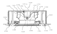
- FIG. 1 is a diagram illustrating the configuration of an indoor unit 100 according to Embodiment 1 of the present invention.
- a four-way cassette type indoor unit 100 that has a ceiling-embedded type that can be embedded in an indoor ceiling and has outlets in four directions will be described.
- the indoor unit 100 is connected to an outdoor unit through a refrigerant pipe, and constitutes a refrigerant circuit that circulates the refrigerant and performs refrigeration, air conditioning, and the like.
- the indoor unit 100 includes a casing 120 that includes a top plate 121 and side plates 122.
- the indoor unit 100 is installed by being embedded in the indoor ceiling with the top plate 121 facing upward.
- the housing 120 is open on the side facing the room (lower side).
- a motor 180 is attached to the top plate 121 on the inner surface side.
- the indoor unit 100 has a substantially rectangular decorative panel 130 attached to the lower side in plan view and faces the room. In the vicinity of the center of the decorative panel 130, a grill 131 serving as an inlet for air (gas) into the indoor unit 100 and a filter 140 for removing air after passing through the grill 131 are provided.
- a main body inlet (bell mouth) 123 that rectifies and flows air into the main body.
- a main body outlet 124 is provided around the main body inlet 123 to allow air to flow out of the main body.
- the grill 131, the main body inlet 123, the main body outlet 124, and the outlet 132 communicate with each other to form an air passage in the indoor unit 100.
- a turbo fan (impeller) 170 Inside the main body of the indoor unit 100, a turbo fan (impeller) 170, a bell mouth 160, a motor 180, an indoor heat exchanger 110, and a heat insulating material 190 are provided.
- the turbo fan 170 is an impeller used for a centrifugal blower to which a rotating shaft 181 of the motor 180 is attached. When the turbo fan 170 rotates, an air flow is formed in which the air sucked through the grill 131 is sent to the side (left and right direction in FIG. 1). The turbo fan 170 will be described later.
- the bell mouth 160 forms a suction air passage for the turbo fan 170 and rectifies it.
- the motor 180 is attached to the top plate 121 so that the central portion of the top plate 121 and the rotation shaft 181 are orthogonal to each other.
- the rotating shaft 181 faces the vertical direction.
- the motor 180 may be attached so as to be in contact with the top plate 121, or may be attached with a slight gap.
- the turbo fan 170 fixed to the rotation shaft 181 rotates around the rotation shaft 181.
- a DC (direct current) motor that consumes less power and generates less heat than driving is used as the motor 180.
- the fin tube type indoor heat exchanger 110 is installed on the downstream side of the turbo fan 170 in the air flow so as to surround the turbo fan 170.
- the indoor heat exchanger 110 functions as an evaporator during cooling operation and functions as a condenser during heating operation.
- each blowout port 132 has a blowout vane (flap) 150 serving as a wind direction deflecting plate for changing the wind direction.
- the position of each blowing vane 150 is controlled by rotating around an axis by driving a motor (not shown).
- the heat insulating material 190 serving as a heat insulating means is attached to the inner surface of the housing 120 by sticking or the like.
- the heat insulating material 190 prevents heat from entering and exiting through the housing 120.
- the heat insulating material 190 is not attached to a portion of the top plate 121 facing the attached motor 180.
- the heat insulating material 190 is not attached, and a portion facing the motor 180 is a heat radiating portion (hole portion) 121a.
- the heat generated by the motor 180 is directly transmitted to the top plate 121.
- the heat transmitted to the top plate 121 is radiated to the outside of the indoor unit 100.
- FIG. 2 is a perspective view showing the configuration of the turbo fan 170 according to Embodiment 1 of the present invention.
- turbo fan 170 When the turbo fan 170 rotates, it sucks air (gas) from the direction of the rotation shaft 181 and blows out the sucked gas in the outer circumferential direction intersecting the rotation shaft 181.
- turbo fan 170 according to the present embodiment is arranged so that shroud (side plate) 1 and main plate 173 are opposed to each other.
- a plurality (seven in FIG. 2) of blades 172 are provided between the shroud 171 and the main plate 173.
- the shroud 171 has a bell mouth shape and has an air suction port 171a at the center.
- the blade 172 forms an air flow from the inside of the turbo fan 170 toward the outer periphery.
- the wing 172 of the present embodiment is a three-dimensional wing having a twisted shape between the shroud 171 and the main plate 173.
- the wing 172 is possible to reduce noise and power consumption.
- the main plate 173 serves as a base of the turbo fan 170 such that the wings 172 are joined.
- the main portion of the main plate 173 has a convex shape toward the inside of the turbo fan 170.
- the central portion of the outer surface side of the main plate 173 is recessed, and the motor 180 is accommodated in a space formed by the recess. Therefore, the main plate 173 covers the motor 180.
- the main plate 173 in the present embodiment partitions the space side where the motor 180 is installed (the outer surface side housing the motor 180) and the inner surface side serving as an air flow path inside the turbofan 170.
- the main plate 173 of the present embodiment does not form a hole that communicates the outer surface side and the inner surface side. By not having a hole, the air flow that passes through the inside of the turbo fan 170 is not disturbed, and the sound that is generated when the air flows from the outer surface side to the inner surface side can be suppressed.
- a boss 174 is attached to the convex center of the main plate 173.
- the turbo fan 170 is attached and fixed to the rotating shaft 181 of the motor 180 via the boss 174.
- an aluminum boss 174 having excellent heat conductivity is used. For this reason, the heat generated by the motor 180 is transmitted to the rotating shaft 181 and the boss 174.
- the boss 174 radiates heat to the air passing through the turbo fan 170.
- air for urging the cooling of the motor 180 is introduced between the main plate 173 of the turbofan 170 and the heat insulating material 190 (the top plate 121) in the space where the motor 180 is installed.
- a cooling channel 175 is formed to pass therethrough.
- FIG. 3 is a view for explaining the flow of air passing through the indoor unit 100 according to Embodiment 1 of the present invention.
- the flow of air that passes through the turbofan 170 and cools the motor 180 will be described.
- the turbo fan 170 fixed to the rotating shaft 181 also rotates.
- an air flow is generated, and air flows from the air suction port 171a of the turbo fan 170 through the grill 131 and the main body suction port 123.
- the air flowing into the turbo fan 170 passes through the turbo fan 170 and flows out from the outer peripheral portion of the turbo fan 170. Most of the air blown out from the outer peripheral portion passes through the indoor heat exchanger 110 and is cooled or heated, for example.
- the cooled or heated air flows out into the room through the main body outlet 124 and the outlet 132.
- a part of the air flowing out from the outer peripheral portion of the turbo fan 170 flows into the cooling flow path 175 between the top plate 121 (the heat insulating material 190) and the main plate 173 of the turbo fan 170.
- the air that flows in cools the motor 180.
- the air between the top plate 121 and the main plate 173 flows out from the portion where the pressure is low in the cooling flow path 175 between the top plate 121 and the main plate 173, and merges with the air that flows out from the turbo fan 170, For example, it passes through the indoor heat exchanger 110.
- the top plate 121 has the heat radiating portion 121a to which the heat insulating material 190 is not attached, and the motor 180 and the top plate 121 are directly opposed to each other. Therefore, the heat generated from the motor 180 can be dissipated through the top plate 121. And since it is not necessary to form a hole for communicating the space where the motor 180 is installed in the main plate 173 and the space inside the turbo fan 170, the generation of noise can be prevented without disturbing the air. In addition, since a flow path for allowing the air flowing out from the turbo fan 170 to pass through the motor 180 and flowing to the indoor heat exchanger 110 can be formed without adding parts, the cost can be reduced. Moreover, in the indoor unit 100 of the present embodiment, by using a DC motor (direct current) as the motor 180, the heat generation of the motor can be suppressed.
- a DC motor direct current
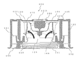
- FIG. FIG. 4 is a diagram illustrating the configuration of the indoor unit 100 according to Embodiment 2 of the present invention.
- the heat radiating portion 121a of the top plate 121 is a bellows-like fin.
- the heat dissipating part 121a is composed of bellows-like fins 121b.
- the top plate 121 and the fins 121b are not integrally formed, and may be configured as separate parts.
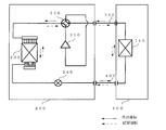
- FIG. 5 is a diagram illustrating a configuration example of an air-conditioning apparatus according to Embodiment 3 of the present invention.
- FIG. 5 shows an air conditioner as an example of a refrigeration cycle apparatus.
- the air conditioner of FIG. 5 connects an outdoor unit (outdoor unit) 200 and an indoor unit (indoor unit) 100 through a gas refrigerant pipe 300 and a liquid refrigerant pipe 400.
- the outdoor unit 200 includes a compressor 210, a four-way valve 220, an outdoor heat exchanger 230, and an expansion valve 240.
- Compressor 210 compresses and discharges the sucked refrigerant.
- the compressor 210 can change the capacity of the compressor 210 (the amount of refrigerant sent out per unit time) by arbitrarily changing the operation frequency by using, for example, an inverter circuit. You may be able to.
- the four-way valve 220 is a valve that switches the flow of the refrigerant between, for example, a cooling operation and a heating operation.
- the outdoor heat exchanger 230 in the present embodiment performs heat exchange between the refrigerant and air (outdoor air). For example, it functions as an evaporator during heating operation, evaporating and evaporating the refrigerant. Moreover, it functions as a condenser during the cooling operation, and condenses and liquefies the refrigerant.
- An expansion valve 240 such as a throttle device (flow rate control means) decompresses the refrigerant to expand it. For example, when an electronic expansion valve is used, the opening degree is adjusted based on an instruction from a control device (not shown).
- the indoor heat exchanger 110 performs heat exchange between air to be air-conditioned and a refrigerant, for example. During heating operation, it functions as a condenser and condenses and liquefies the refrigerant. Moreover, it functions as an evaporator during cooling operation, evaporating and evaporating the refrigerant.
- the cooling operation in the refrigeration cycle apparatus will be described based on the refrigerant flow.
- the four-way valve 220 is switched so as to have a connection relationship indicated by a solid line.
- the high-temperature and high-pressure gas refrigerant compressed and discharged by the compressor 210 passes through the four-way valve 220 and flows into the outdoor heat exchanger 230.
- the refrigerant (liquid refrigerant) condensed and liquefied by passing through the outdoor heat exchanger 230 and exchanging heat with outdoor air flows into the expansion valve 240.
- the refrigerant that has been decompressed by the expansion valve 240 and is in a gas-liquid two-phase state flows out of the outdoor unit 200.
- the gas-liquid two-phase refrigerant that has flowed out of the outdoor unit 200 passes through the liquid refrigerant pipe 400 and flows into the indoor unit 100. Then, it is distributed by a distributor and a flow rate adjusting capillary (not shown) and flows into the indoor heat exchanger 110. As described above, the refrigerant (gas refrigerant) evaporated and gasified by passing through the indoor heat exchanger 110 and exchanging heat with air to be air-conditioned, for example, flows out of the indoor unit 100.
- the gas refrigerant flowing out from the indoor unit 100 passes through the gas refrigerant pipe 300 and flows into the outdoor unit 200. Then, it passes through the four-way valve 220 and is sucked into the compressor 210 again. As described above, the refrigerant of the air conditioner circulates and performs air conditioning (cooling).
- the heating operation will be described based on the refrigerant flow.
- the four-way valve 220 is switched so as to have a connection relationship indicated by a dotted line.
- the high-temperature and high-pressure gas refrigerant compressed and discharged by the compressor 210 passes through the four-way valve 220 and flows out of the outdoor unit 200.
- the gas refrigerant that has flowed out of the outdoor unit 200 passes through the gas refrigerant pipe 300 and flows into the indoor unit 100.
- the refrigerant that has flowed out of the indoor unit 100 passes through the liquid refrigerant pipe 400 and flows into the outdoor unit 200. Then, the refrigerant that has been decompressed by the expansion valve 240 and is in a gas-liquid two-phase state flows into the outdoor heat exchanger 230. Then, the refrigerant (liquid refrigerant) evaporated and gasified by passing through the outdoor heat exchanger 230 and exchanging heat with outdoor air passes through the four-way valve 220 and is sucked into the compressor 210 again. As described above, the refrigerant of the air conditioner circulates and performs air conditioning (heating).
- the indoor unit 100 has been described as a four-way cassette type indoor unit that has four outlets 132 and the outlet vanes 150 and blows out air in four directions. It is not a thing.
- the present invention can also be applied to other ceiling-embedded indoor units corresponding to two-way and three-way air flows. Further, the present invention can be applied not only to the ceiling-embedded indoor unit but also to other types of indoor units.
- the air conditioner has been described as an example of the refrigeration cycle apparatus, but the present invention is not limited to this.
- the present invention can be applied to other refrigeration cycle apparatuses such as a refrigeration apparatus and a refrigeration apparatus.
- it can be applied not only to the refrigeration cycle apparatus but also to a blower, a ventilator, or the like.
Abstract
この発明に係る室内機100は、天板121と側板122とを具備する筐体120と、天板121の内面側の中央部分に、天板121と対向して設置されるモータ180と、モータ180の回転軸181に固定され、モータ180の駆動により回転されるターボファン170と、筐体120の内面側に設置される断熱材190とを有し、ターボファン170から流出した空気の一部を、モータ180が設置された空間に送る冷却流路175をターボファン170と天板121との間に形成し、モータ180と天板121とが対向する部分には断熱材190を設置しないようにする。
Description
この発明は、たとえば空気調和装置などの室内機などに係るものである。特にモータの放熱などに関するものである。
空気調和装置などにおいて、室内側に設置する室内機は、たとえば室内に空気を送り込む(送風する)送風機を備えている。送風機は、電動機(モータ)を駆動し、ファン(羽根車)を回して送風する。ここで、モータは、駆動によって発熱するため、放熱(冷却)させる必要がある。
たとえば、ターボファン(羽根車)を回転させて送風する天井埋込型の室内機では、モータの回転軸と固定される主板において、凸形状で形成された凸部を有し、モータを覆っている。従来、主板の凸部に、モータ側の面と風路となるファン内部側の面とを貫通する開口穴を設けていた。ターボファンを流出した空気の一部は、負圧によってモータ側に案内される。そして、モータは通過する空気に放熱する。放熱された空気は、開口穴からターボファン内部へ流入し、羽根車を流出する空気と合流する。以上の空気の流路を形成することでモータを冷却するものであった(たとえば、特許文献1参照)。このとき、開口穴をターボファンの凸部の麓に開口穴を設けて、騒音低減をはかるものもある(たとえば、特許文献2参照)。
また、特許文献1には、ターボファンから吹き出した空気の一部をモータ側へ案内する経路とモータ側からターボファンの流出側に案内する経路とを形成する仕切板を筺体天板と羽根車との間に設けている室内機についても記載されている。
上記のように、たとえば、モータ側の面とファン内部側の面とを貫通する開口穴を主板に設けると、ファン内部の圧力が変動し、騒音が発生する原因となる。また、仕切り板等が構成部品として必要となり、部品コストが高くなる原因となる。
この発明は、上記の課題を解決するためになされたもので、騒音、構成部品点数などを増やさずに、モータを放熱することができる室内機などを得ることを目的とする。
この発明に係る室内機は、天板と側板とを具備する筐体と、天板の内面側の中央部分に、天板と対向して設置されるモータと、モータの回転軸に固定され、モータの駆動により回転されるファンと、筐体の内面側に設置される断熱手段とを有し、ファンから流出した空気の一部を、モータが設置された空間に送る流路をファンと天板との間に形成し、モータと天板とが対向する部分には断熱手段を設置しないようにするものである。
この発明によれば、天板において、モータと天板とが対向する部分には断熱手段を取り付けないようにすることで、モータから発生した熱を天板を介して放熱させることができる室内機を得ることができる。このとき、ファンに流入出する空気の流れを阻害することなく、部品を追加してモータへの流路を確保する必要がないので、騒音およびコストを抑えることができる。
以下、この発明を実施するための形態について、図面を参照して説明する。ここで、参照符号について、以下の図面において、同一の符号を付したものは、同一またはこれに相当するものであり、このことは、明細書の全文において共通することである。そして、明細書全文に表わされている構成要素の形態は、あくまでも例示であって、明細書に記載された形態に限定するものではない。特に構成要素の組み合わせは、各実施の形態における組み合わせのみに限定するものではなく、他の実施の形態に記載した構成要素を別の実施の形態に適用することができる。また、複数枚有する翼に関する符号は、代表の1枚にのみ付すものとする。また、図などに示した翼の枚数は一例である。さらに、図における上方を「上側」とし、下方を「下側」として説明する。そして、図面では各構成部材の大きさの関係が実際のものとは異なる場合がある。
実施の形態1.
図1はこの発明の実施の形態1に係る室内機100の構成を説明する図である。本実施の形態では、室内の天井に埋め込むことができる天井埋め込み型で、四方向に吹き出し口を有する四方向カセット型の室内機100について説明する。室内機100は、冷媒配管により室外機と接続し、冷媒を循環して冷凍、空気調和などを行う冷媒回路を構成する。
図1はこの発明の実施の形態1に係る室内機100の構成を説明する図である。本実施の形態では、室内の天井に埋め込むことができる天井埋め込み型で、四方向に吹き出し口を有する四方向カセット型の室内機100について説明する。室内機100は、冷媒配管により室外機と接続し、冷媒を循環して冷凍、空気調和などを行う冷媒回路を構成する。
図1に示すように、室内機100は、天板121および側板122で構成される筐体120を有する。室内機100は、天板121が上方となる向きに室内の天井に埋め込まれて設置される。筐体120は室内に面する側(下方側)が開口している。天板121にはモータ180が内面側に取り付けられる。また、室内機100は、平面視で略四角形状の化粧パネル130が下方側に取り付けられ、室内に面している。化粧パネル130の中央付近には、室内機100内への空気(気体)の吸い込み口となるグリル131と、グリル131通過後に空気を除塵するフィルタ140とを備えている。
室内機100の下面中央部には、本体内に空気を整流して流入させる本体吸い込み口(ベルマウス)123を有している。また、本体吸い込み口123の周囲には、本体内から空気を流出させる本体吹き出し口124を有している。そして、グリル131、本体吸い込み口123、本体吹き出し口124および吹き出し口132が連通し、室内機100内の風路を形成している。
室内機100の本体内部には、ターボファン(羽根車)170、ベルマウス160、モータ180および室内熱交換器110、断熱材190を有している。ターボファン170はモータ180が有する回転軸181が取り付けられた遠心型の送風機に用いられる羽根車である。ターボファン170が回転することにより、グリル131を介して吸い込んだ空気を側方(図1の左右方向)に送り出す空気の流れを形成する。ターボファン170については後述する。また、ベルマウス160はターボファン170の吸い込み風路を形成し、整流する。
モータ180は、前述したように、モータ180は、天板121の中央部分と回転軸181とが直交するように天板121に取り付けられる。たとえば、回転軸181は鉛直方向を向くことになる。ここで、たとえばモータ180を天板121に接するように取り付けるようにしてもよい、また、少し隙間を有して取り付けてもよい。モータ180が駆動すると、回転軸181に固定されたターボファン170が回転軸181を中心に回転する。本実施の形態においては、消費電力が少なく、駆動に比して発熱量が少ないDC(直流)モータをモータ180として用いる。
たとえばフィンチューブ型の室内熱交換器110は、空気の流れにおいてターボファン170の下流側に、ターボファン170を囲むように設置している。たとえば空気調和装置に、本実施の形態の室内機100を適用する際、室内熱交換器110は、冷房運転時には蒸発器として機能し、暖房運転時には凝縮器として機能する。
化粧パネル130の各辺には、空気の吹き出し口132が、化粧パネル130の各辺に沿って形成されている。本実施の形態の室内機100は、4つの吹き出し口132を有している。各吹き出し口132には、風向きを変更する風向偏向板となる吹き出しベーン(フラップ)150を有している。各吹き出しベーン150は、モータ(図示せず)の駆動により軸を中心に回転移動することで位置制御が行われる。
断熱手段となる断熱材190は、貼るなどして筐体120内側の面に取り付けられる。断熱材190は、筐体120を介した熱の出入りを防ぐ。ここで、本実施の形態では、天板121において、取り付けられたモータ180と対向する部分には、断熱材190を取り付けないようにする。天板121において、断熱材190が取り付けられておらず、モータ180と対向する部分を放熱部(穴部)121aとする。放熱部(穴部)121aにおいては、モータ180が発した熱が天板121に直接的に伝わる。天板121に伝わった熱は室内機100外部に放熱される。
図2はこの発明の実施の形態1に係るターボファン170の構成を示す斜視図である。ターボファン170は、回転すると、回転軸181方向から空気(気体)を吸入し、吸入した気体を回転軸181と交差する外周方向に吹き出す。本実施の形態に係るターボファン170は、図2に示すように、シュラウド(側板)1と主板173とを対向させるように配置する。そして、シュラウド171と主板173との間に複数(図2では7枚)の翼172が設けられている。シュラウド171は、ベルマウス形状をしており、中央部分に空気吸い込み口171aを有する。
翼172は、ターボファン170内から外周方向への空気の流れを形成する。ここで、本実施の形態の翼172は、シュラウド171と主板173との間において、ねじれた形状を有する3次元翼である。翼172が3次元翼とすることで、低騒音化、低消費電力化などをはかることができる。
主板173は、翼172が接合されるなど、ターボファン170の土台となる。主板173は、ターボファン170の内側に向かって中央部分が凸状を形成している。このため、主板173の外面側は中央部分が凹んでおり、凹むことでできる空間にモータ180を収容している。したがって、主板173はモータ180を覆っている。ここで、本実施の形態における主板173には、モータ180が設置された空間側(モータ180を収容する外面側)とターボファン170内部における空気の流路となる内面側とを仕切っている。このため、本実施の形態の主板173は、外面側と内面側とを連通する穴を形成しない。穴を有していないことで、ターボファン170内部を通過する空気の流れに乱れが生じず、外面側から内面側に空気が流れることで発生する音を抑えることができる。
また、主板173の凸状中央にはボス174が取り付けられる。ボス174を介して、モータ180の回転軸181にターボファン170を取り付けて固定する。本実施の形態では、伝熱性に優れたアルミニウム製のボス174を用いるものとする。このため、モータ180が発した熱は回転軸181およびボス174に伝達する。そして、ボス174がターボファン170内を通過する空気に放熱する。
ここで、後述する図3に示すように、ターボファン170の主板173と断熱材190(天板121)との間には、モータ180の冷却を促す空気をモータ180が設置されている空間に通過させる冷却流路175が形成されている。冷却流路175を形成することで、モータ180に空気を供給できるだけでなく、ターボファン170が回転時に振動して、ターボファン170の主板173と断熱材190(天板121)とが接触などしないようにするための隙間(空隙)となる。
図3はこの発明の実施の形態1に係る室内機100内を通過する空気の流れを説明する図である。ここでは、特にターボファン170を通過してモータ180を冷却する空気の流れについて説明する。モータ180が駆動して回転軸181が回転することで、回転軸181に固定したターボファン170も回転する。ターボファン170が回転すると、気流が発生し、グリル131、本体吸い込み口123を介してターボファン170の空気吸い込み口171aから空気が流入する。ターボファン170に流入した空気は、ターボファン170を通過して、ターボファン170の外周部分から流出する。外周部分から吹き出された空気は、大部分が室内熱交換器110を通過し、たとえば冷却または加熱される。冷却または加熱された空気は本体吹き出し口124および吹き出し口132を通って室内に流出する。
一方、ターボファン170の外周部分から流出した空気の一部は、天板121(断熱材190)とターボファン170の主板173との間の冷却流路175に流入する。流入した空気はモータ180を冷却する。そして、天板121と主板173との間の空気は、天板121と主板173との間の冷却流路175において圧力が低い部分から流出し、ターボファン170から流出した空気と合流して、たとえば室内熱交換器110を通過する。
以上のように、本実施の形態の室内機100においては、天板121において、断熱材190を取り付けていない放熱部121aを有し、モータ180と天板121との間を直接対向させるようにしたので、モータ180から発生した熱を天板121を介して放熱させることができる。そして、主板173にモータ180が設置された空間とターボファン170内部の空間とを連通させる穴を形成する必要がないので、穴が空気を乱すことなく騒音の発生を防ぐことができる。また、部品を追加することなく、ターボファン170から流出した空気をモータ180に通過させて室内熱交換器110に流す流路を形成することができるので、コストを抑えることができる。また、本実施の形態の室内機100においては、モータ180にDCモータ(直流)を用いることにより、モータの発熱を抑えることができる。
実施の形態2.
図4はこの発明の実施の形態2に係る室内機100の構成を説明する図である。図4において、図1などと同じ符号を付している装置などについては、実施の形態1で説明したことと同様の動作、機能を果たすものである。本実施の形態は、天板121が有する放熱部121aを蛇腹状のフィンとしたものである。放熱部121aを蛇腹状のフィン121bで構成する。蛇腹状のフィン121bとすることで、放熱部121aにおいて、室内機100外の空間との間の伝熱面積を増やすことができ、放熱効果をより高めることができる。ここで、天板121とフィン121bとは、一体形成したものでなく、別部品で構成してもよい。
図4はこの発明の実施の形態2に係る室内機100の構成を説明する図である。図4において、図1などと同じ符号を付している装置などについては、実施の形態1で説明したことと同様の動作、機能を果たすものである。本実施の形態は、天板121が有する放熱部121aを蛇腹状のフィンとしたものである。放熱部121aを蛇腹状のフィン121bで構成する。蛇腹状のフィン121bとすることで、放熱部121aにおいて、室内機100外の空間との間の伝熱面積を増やすことができ、放熱効果をより高めることができる。ここで、天板121とフィン121bとは、一体形成したものでなく、別部品で構成してもよい。
実施の形態3.
図5はこの発明の実施の形態3に係る空気調和装置の構成例を表す図である。ここで、図5では空気調和装置を冷凍サイクル装置の例として示している。図5において、図1などにおいて説明したものについては、同様の動作を行うものとする。図5の空気調和装置は、室外機(室外ユニット)200と室内機(室内ユニット)100とをガス冷媒配管300、液冷媒配管400により配管接続する。室外機200は、圧縮機210、四方弁220、室外熱交換器230および膨張弁240を有している。
図5はこの発明の実施の形態3に係る空気調和装置の構成例を表す図である。ここで、図5では空気調和装置を冷凍サイクル装置の例として示している。図5において、図1などにおいて説明したものについては、同様の動作を行うものとする。図5の空気調和装置は、室外機(室外ユニット)200と室内機(室内ユニット)100とをガス冷媒配管300、液冷媒配管400により配管接続する。室外機200は、圧縮機210、四方弁220、室外熱交換器230および膨張弁240を有している。
圧縮機210は、吸入した冷媒を圧縮して吐出する。ここで、特に限定するものではないが、圧縮機210はたとえばインバータ回路などにより、運転周波数を任意に変化させることにより、圧縮機210の容量(単位時間あたりの冷媒を送り出す量)を変化させることができるようにしてもよい。四方弁220は、たとえば冷房運転時と暖房運転時とによって冷媒の流れを切り換える弁である。
本実施の形態における室外熱交換器230は、冷媒と空気(室外の空気)との熱交換を行う。たとえば、暖房運転時においては蒸発器として機能し、冷媒を蒸発させ、気化させる。また、冷房運転時においては凝縮器として機能し、冷媒を凝縮して液化させる。
絞り装置(流量制御手段)などの膨張弁240は冷媒を減圧して膨張させる。たとえば電子式膨張弁などで構成した場合には、制御装置(図示せず)などの指示に基づいて開度調整を行う。室内熱交換器110は、たとえば空調対象となる空気と冷媒との熱交換を行う。暖房運転時においては凝縮器として機能し、冷媒を凝縮して液化させる。また、冷房運転時においては蒸発器として機能し、冷媒を蒸発させ、気化させる。
最初に、冷凍サイクル装置における冷房運転について冷媒の流れに基づいて説明する。冷房運転においては、実線で示す接続関係となるように四方弁220を切り替える。圧縮機210により圧縮されて吐出した高温、高圧のガス冷媒は、四方弁220を通過し、室外熱交換器230に流入する。そして、室外熱交換器230内を通過して、室外の空気と熱交換することで凝縮、液化した冷媒(液冷媒)は、膨張弁240へ流入する。膨張弁240で減圧されて気液二相状態となった冷媒は室外機200から流出する。
室外機200を流出した気液二相冷媒は、液冷媒配管400を通過して室内機100に流入する。そして、ディストリビュータおよび流量調整用毛細管(図示せず)により分配され、室内熱交換器110に流入する。前述したように室内熱交換器110を通過して、たとえば空調対象の空気と熱交換することで蒸発、ガス化した冷媒(ガス冷媒)は、室内機100から流出する。
室内機100から流出したガス冷媒はガス冷媒配管300を通過して室外機200に流入する。そして、四方弁220を通過して再度圧縮機210に吸入される。以上のようにして空気調和装置の冷媒が循環し、空気調和(冷房)を行う。
次に暖房運転について冷媒の流れに基づいて説明する。暖房運転においては、点線で示す接続関係となるように四方弁220を切り替える。圧縮機210により圧縮されて吐出した高温、高圧のガス冷媒は、四方弁220を通過して室外機200から流出する。室外機200を流出したガス冷媒は、ガス冷媒配管300を通過して室内機100に流入する。
室内熱交換器110を通過して、たとえば空調対象の空気と熱交換することで凝縮、液化した冷媒は、ディストリビュータおよび流量調整用毛細管(図示せず)とを通過して室内機100から流出する。
室内機100から流出した冷媒は液冷媒配管400を通過して室外機200に流入する。そして、膨張弁240で減圧されて気液二相状態となった冷媒は室外熱交換器230に流入する。そして、室外熱交換器230内を通過して、室外の空気と熱交換することで蒸発、ガス化した冷媒(液冷媒)は、四方弁220を通過して再度圧縮機210に吸入される。以上のようにして空気調和装置の冷媒が循環し、空気調和(暖房)を行う。
以上のように、本実施の形態の空気調和装置(冷凍サイクル装置)においては、上述の室内機100を用いて構成することで、直風回避をしつつ、スマッジングを低減することができる。
上述の実施の形態では、室内機100は4つの吹き出し口132と吹き出しベーン150とを有し、四方向の空気を吹き出す四方向カセット型の室内機であるものとして説明したが、これに限定するものではない。たとえば、二方向、三方向の空気の流れに対応する、他の天井埋め込み型の室内機についても適用することができる。また、天井埋め込み型の室内機に限らず、他の型式の室内機にも適用することができる。
また、上述の実施の形態では、冷凍サイクル装置の例として空気調和装置について説明したが、これに限定するものではない。たとえば冷蔵装置、冷凍装置など、他の冷凍サイクル装置にも適用することができる。また、冷凍サイクル装置だけでなく、送風機、換気装置などにも適用することができる。
100 室内機、110 室内熱交換器、120 筐体、121 天板、121a 放熱部、121b フィン、122 側板、123 本体吸い込み口、124 本体吹き出し口、130 化粧パネル、131 グリル、132 吹き出し口、140 フィルタ、150 吹き出しベーン、160 ベルマウス、170 ターボファン、171 シュラウド、171a 空気吸い込み口、172 翼、173 主板、174 ボス、175 冷却流路、180 モータ、181 回転軸、190 断熱材、200 室外機、210 圧縮機、220 四方弁、230 室外熱交換器、240 膨張弁、300 ガス冷媒配管、400 液冷媒配管。
Claims (7)
- 天板と側板とを具備する筐体と、
前記天板の内面側の中央部分に、前記天板と対向して設置されるモータと、
該モータの回転軸に固定され、前記モータの駆動により回転されるファンと、
前記筐体の内面側に設置される断熱手段とを有し、
前記ファンから流出した空気の一部を、前記モータが設置された空間に送る流路を前記ファンと前記天板との間に形成し、前記モータと前記天板とが対向する部分には前記断熱手段を設置しないようにする室内機。 - 前記ファンは、
前記回転軸に固定される主板と、
該主板と対向し、気体が流入する吸い込み口を有するシュラウドと、
前記主板と前記シュラウドとの間に配置される複数の翼とを有し、
ファン内部に流入した空気を、前記回転軸と直交する方向に流出させる遠心ファンであり、
前記主板は、前記モータが設置された空間と前記ファン内部の空間とを仕切る請求項1に記載の室内機。 - アルミ材を用いたボスにより、前記ファンと前記回転軸とを固定する請求項1または請求項2に記載の室内機。
- 前記モータを直流モータとする請求項1~請求項3のいずれか一項に記載の室内機。
- 前記天板は、前記モータと対向する面に放熱手段を有する請求項1~請求項4のいずれか一項に記載の室内機。
- 前記放熱手段は、蛇腹状のフィンである請求項5に記載の室内機。
- 請求項1~請求項6のいずれか一項に記載の室内機と、
該室内機側に熱供給を行う室外機と
を備える空気調和装置。
Priority Applications (4)
| Application Number | Priority Date | Filing Date | Title |
|---|---|---|---|
| JP2017513912A JP6516833B2 (ja) | 2015-04-23 | 2015-04-23 | 室内機および空気調和装置 |
| PCT/JP2015/062420 WO2016170652A1 (ja) | 2015-04-23 | 2015-04-23 | 室内機および空気調和装置 |
| CN201610139440.4A CN106066060A (zh) | 2015-04-23 | 2016-03-11 | 室内机以及空调装置 |
| CN201620189130.9U CN205481354U (zh) | 2015-04-23 | 2016-03-11 | 室内机以及空调装置 |
Applications Claiming Priority (1)
| Application Number | Priority Date | Filing Date | Title |
|---|---|---|---|
| PCT/JP2015/062420 WO2016170652A1 (ja) | 2015-04-23 | 2015-04-23 | 室内機および空気調和装置 |
Publications (1)
| Publication Number | Publication Date |
|---|---|
| WO2016170652A1 true WO2016170652A1 (ja) | 2016-10-27 |
Family
ID=56656198
Family Applications (1)
| Application Number | Title | Priority Date | Filing Date |
|---|---|---|---|
| PCT/JP2015/062420 WO2016170652A1 (ja) | 2015-04-23 | 2015-04-23 | 室内機および空気調和装置 |
Country Status (3)
| Country | Link |
|---|---|
| JP (1) | JP6516833B2 (ja) |
| CN (2) | CN106066060A (ja) |
| WO (1) | WO2016170652A1 (ja) |
Families Citing this family (3)
| Publication number | Priority date | Publication date | Assignee | Title |
|---|---|---|---|---|
| JP6516833B2 (ja) * | 2015-04-23 | 2019-05-22 | 三菱電機株式会社 | 室内機および空気調和装置 |
| EP3596404A4 (en) * | 2017-03-17 | 2020-03-25 | Zhang, Yiyan | AIR CONDITIONING UNIT |
| KR102313903B1 (ko) * | 2017-05-25 | 2021-10-18 | 엘지전자 주식회사 | 천장형 공기조화기 |
Citations (4)
| Publication number | Priority date | Publication date | Assignee | Title |
|---|---|---|---|---|
| JPH06173896A (ja) * | 1992-12-04 | 1994-06-21 | Toshiba Corp | 送風機および空気調和機の室外ユニット |
| JP2003232542A (ja) * | 2002-02-07 | 2003-08-22 | Sanyo Electric Co Ltd | 空気調和装置 |
| JP2006266664A (ja) * | 2005-02-24 | 2006-10-05 | Mitsubishi Electric Corp | 天井埋込型空気調和機 |
| JP2014215022A (ja) * | 2013-04-30 | 2014-11-17 | ダイキン工業株式会社 | 空気調和機の室内ユニット |
Family Cites Families (5)
| Publication number | Priority date | Publication date | Assignee | Title |
|---|---|---|---|---|
| JP3285505B2 (ja) * | 1996-11-20 | 2002-05-27 | 東芝キヤリア株式会社 | 天井カセット形空気調和装置のファンモータ取付構造 |
| JP3957927B2 (ja) * | 1999-08-30 | 2007-08-15 | 三菱重工業株式会社 | 天井埋込型空気調和装置 |
| WO2004079270A1 (ja) * | 2003-03-04 | 2004-09-16 | Matsushita Electric Industrial Co., Ltd. | エアフィルタの自動清掃機能付き室内ユニットを備えた空気調和機 |
| JP5500275B2 (ja) * | 2013-01-18 | 2014-05-21 | パナソニック株式会社 | 送風装置 |
| JP6516833B2 (ja) * | 2015-04-23 | 2019-05-22 | 三菱電機株式会社 | 室内機および空気調和装置 |
-
2015
- 2015-04-23 JP JP2017513912A patent/JP6516833B2/ja not_active Expired - Fee Related
- 2015-04-23 WO PCT/JP2015/062420 patent/WO2016170652A1/ja active Application Filing
-
2016
- 2016-03-11 CN CN201610139440.4A patent/CN106066060A/zh active Pending
- 2016-03-11 CN CN201620189130.9U patent/CN205481354U/zh active Active
Patent Citations (4)
| Publication number | Priority date | Publication date | Assignee | Title |
|---|---|---|---|---|
| JPH06173896A (ja) * | 1992-12-04 | 1994-06-21 | Toshiba Corp | 送風機および空気調和機の室外ユニット |
| JP2003232542A (ja) * | 2002-02-07 | 2003-08-22 | Sanyo Electric Co Ltd | 空気調和装置 |
| JP2006266664A (ja) * | 2005-02-24 | 2006-10-05 | Mitsubishi Electric Corp | 天井埋込型空気調和機 |
| JP2014215022A (ja) * | 2013-04-30 | 2014-11-17 | ダイキン工業株式会社 | 空気調和機の室内ユニット |
Also Published As
| Publication number | Publication date |
|---|---|
| CN106066060A (zh) | 2016-11-02 |
| JPWO2016170652A1 (ja) | 2017-11-02 |
| JP6516833B2 (ja) | 2019-05-22 |
| CN205481354U (zh) | 2016-08-17 |
Similar Documents
| Publication | Publication Date | Title |
|---|---|---|
| JP6732037B2 (ja) | 室内機および空気調和装置 | |
| JP6940619B2 (ja) | 遠心送風機、送風装置、空気調和装置及び冷凍サイクル装置 | |
| JP5295321B2 (ja) | 送風機、室外機及び冷凍サイクル装置 | |
| JP6639654B2 (ja) | 空気調和機 | |
| WO2016170652A1 (ja) | 室内機および空気調和装置 | |
| JPWO2017199444A1 (ja) | 遠心送風機、空気調和装置および冷凍サイクル装置 | |
| WO2020213031A1 (ja) | 送風機、空気調和装置の室内機および空気調和装置 | |
| JPWO2019171462A1 (ja) | 室内機および空気調和機 | |
| JP2015121342A (ja) | 室内機及び空気調和機 | |
| JP5794866B2 (ja) | 空気調和装置の室内機 | |
| CN109891101B (zh) | 螺旋桨风扇、室外机和制冷循环装置 | |
| JPWO2018003103A1 (ja) | 空気調和機、空気調和装置および冷凍サイクル装置 | |
| US10302313B2 (en) | Indoor unit and air-conditioning apparatus | |
| JP5558449B2 (ja) | 送風機、室外機及び冷凍サイクル装置 | |
| JPWO2019116838A1 (ja) | 熱交換ユニット及びこれを搭載する空気調和装置 | |
| JP6925571B1 (ja) | 送風機、室内機および空気調和装置 | |
| WO2022107209A1 (ja) | 室内機及び冷凍サイクル装置 | |
| WO2017060973A1 (ja) | 送風装置、室外機及び冷凍サイクル装置 | |
| WO2023223383A1 (ja) | クロスフローファン、送風装置及び冷凍サイクル装置 | |
| JP2000274807A (ja) | 室内ユニット及び空気調和機 | |
| KR100335082B1 (ko) | 창문형 에어컨의 실외기 | |
| WO2019198150A1 (ja) | 空気調和機 | |
| WO2020121938A1 (ja) | 送風装置 | |
| WO2018189779A1 (ja) | 電動機、送風機、室外機、及び、空気調和機 | |
| EP3196560B1 (en) | Indoor unit for air conditioning device, and air conditioning device |
Legal Events
| Date | Code | Title | Description |
|---|---|---|---|
| 121 | Ep: the epo has been informed by wipo that ep was designated in this application |
Ref document number: 15889891 Country of ref document: EP Kind code of ref document: A1 |
|
| ENP | Entry into the national phase |
Ref document number: 2017513912 Country of ref document: JP Kind code of ref document: A |
|
| NENP | Non-entry into the national phase |
Ref country code: DE |
|
| 122 | Ep: pct application non-entry in european phase |
Ref document number: 15889891 Country of ref document: EP Kind code of ref document: A1 |