WO2016167161A1 - 保護膜およびその製造方法 - Google Patents
保護膜およびその製造方法 Download PDFInfo
- Publication number
- WO2016167161A1 WO2016167161A1 PCT/JP2016/061168 JP2016061168W WO2016167161A1 WO 2016167161 A1 WO2016167161 A1 WO 2016167161A1 JP 2016061168 W JP2016061168 W JP 2016061168W WO 2016167161 A1 WO2016167161 A1 WO 2016167161A1
- Authority
- WO
- WIPO (PCT)
- Prior art keywords
- film
- groove
- protective film
- processing
- protective
- Prior art date
Links
- 230000001681 protective effect Effects 0.000 title claims abstract description 213
- 238000004519 manufacturing process Methods 0.000 title claims description 10
- 239000000463 material Substances 0.000 claims abstract description 76
- 238000000151 deposition Methods 0.000 claims abstract description 13
- 238000012545 processing Methods 0.000 claims description 151
- 239000000758 substrate Substances 0.000 claims description 56
- 238000005520 cutting process Methods 0.000 claims description 28
- 229910052751 metal Inorganic materials 0.000 claims description 19
- 239000002184 metal Substances 0.000 claims description 19
- OKTJSMMVPCPJKN-UHFFFAOYSA-N Carbon Chemical compound [C] OKTJSMMVPCPJKN-UHFFFAOYSA-N 0.000 claims description 17
- 229910052799 carbon Inorganic materials 0.000 claims description 14
- 238000005530 etching Methods 0.000 claims description 14
- 238000000227 grinding Methods 0.000 claims description 13
- 239000004033 plastic Substances 0.000 claims description 13
- 229910003460 diamond Inorganic materials 0.000 claims description 12
- 239000010432 diamond Substances 0.000 claims description 12
- 238000001746 injection moulding Methods 0.000 claims description 12
- 239000011347 resin Substances 0.000 claims description 12
- 229920005989 resin Polymers 0.000 claims description 12
- XLYOFNOQVPJJNP-UHFFFAOYSA-N water Substances O XLYOFNOQVPJJNP-UHFFFAOYSA-N 0.000 claims description 12
- 238000005266 casting Methods 0.000 claims description 11
- 238000010438 heat treatment Methods 0.000 claims description 11
- 238000007747 plating Methods 0.000 claims description 10
- 229910018072 Al 2 O 3 Inorganic materials 0.000 claims description 8
- 229910004298 SiO 2 Inorganic materials 0.000 claims description 8
- ATJFFYVFTNAWJD-UHFFFAOYSA-N Tin Chemical compound [Sn] ATJFFYVFTNAWJD-UHFFFAOYSA-N 0.000 claims description 8
- 239000012528 membrane Substances 0.000 claims description 2
- 239000002023 wood Substances 0.000 claims 1
- 238000003754 machining Methods 0.000 abstract description 7
- 230000006378 damage Effects 0.000 abstract description 4
- 238000000034 method Methods 0.000 description 27
- 230000035882 stress Effects 0.000 description 24
- 239000007789 gas Substances 0.000 description 10
- 230000000873 masking effect Effects 0.000 description 8
- 230000015572 biosynthetic process Effects 0.000 description 7
- 239000012141 concentrate Substances 0.000 description 6
- 238000005498 polishing Methods 0.000 description 6
- 230000000644 propagated effect Effects 0.000 description 5
- XKRFYHLGVUSROY-UHFFFAOYSA-N Argon Chemical compound [Ar] XKRFYHLGVUSROY-UHFFFAOYSA-N 0.000 description 4
- CURLTUGMZLYLDI-UHFFFAOYSA-N Carbon dioxide Chemical compound O=C=O CURLTUGMZLYLDI-UHFFFAOYSA-N 0.000 description 4
- 230000006355 external stress Effects 0.000 description 4
- 229910002804 graphite Inorganic materials 0.000 description 4
- 239000010439 graphite Substances 0.000 description 4
- IJGRMHOSHXDMSA-UHFFFAOYSA-N Atomic nitrogen Chemical compound N#N IJGRMHOSHXDMSA-UHFFFAOYSA-N 0.000 description 3
- 229910000831 Steel Inorganic materials 0.000 description 3
- 229910052786 argon Inorganic materials 0.000 description 3
- 239000011248 coating agent Substances 0.000 description 3
- 238000000576 coating method Methods 0.000 description 3
- 230000008021 deposition Effects 0.000 description 3
- 230000000694 effects Effects 0.000 description 3
- 239000012530 fluid Substances 0.000 description 3
- 239000000314 lubricant Substances 0.000 description 3
- 230000001590 oxidative effect Effects 0.000 description 3
- 238000003908 quality control method Methods 0.000 description 3
- 239000007787 solid Substances 0.000 description 3
- 239000010959 steel Substances 0.000 description 3
- VYZAMTAEIAYCRO-UHFFFAOYSA-N Chromium Chemical compound [Cr] VYZAMTAEIAYCRO-UHFFFAOYSA-N 0.000 description 2
- PXHVJJICTQNCMI-UHFFFAOYSA-N Nickel Chemical compound [Ni] PXHVJJICTQNCMI-UHFFFAOYSA-N 0.000 description 2
- 229910045601 alloy Inorganic materials 0.000 description 2
- 239000000956 alloy Substances 0.000 description 2
- 238000005452 bending Methods 0.000 description 2
- 229910002092 carbon dioxide Inorganic materials 0.000 description 2
- 239000001569 carbon dioxide Substances 0.000 description 2
- 239000003575 carbonaceous material Substances 0.000 description 2
- 230000007797 corrosion Effects 0.000 description 2
- 238000005260 corrosion Methods 0.000 description 2
- 239000007888 film coating Substances 0.000 description 2
- 238000009501 film coating Methods 0.000 description 2
- 238000005240 physical vapour deposition Methods 0.000 description 2
- 238000005268 plasma chemical vapour deposition Methods 0.000 description 2
- 239000000843 powder Substances 0.000 description 2
- 238000003672 processing method Methods 0.000 description 2
- 239000000243 solution Substances 0.000 description 2
- 239000004071 soot Substances 0.000 description 2
- 238000005496 tempering Methods 0.000 description 2
- WFKWXMTUELFFGS-UHFFFAOYSA-N tungsten Chemical compound [W] WFKWXMTUELFFGS-UHFFFAOYSA-N 0.000 description 2
- 238000010146 3D printing Methods 0.000 description 1
- 229910000838 Al alloy Inorganic materials 0.000 description 1
- 229910000881 Cu alloy Inorganic materials 0.000 description 1
- 229910000861 Mg alloy Inorganic materials 0.000 description 1
- CBENFWSGALASAD-UHFFFAOYSA-N Ozone Chemical compound [O-][O+]=O CBENFWSGALASAD-UHFFFAOYSA-N 0.000 description 1
- 229910019142 PO4 Inorganic materials 0.000 description 1
- 229910001069 Ti alloy Inorganic materials 0.000 description 1
- 229910001080 W alloy Inorganic materials 0.000 description 1
- 239000006061 abrasive grain Substances 0.000 description 1
- 238000002048 anodisation reaction Methods 0.000 description 1
- QVGXLLKOCUKJST-UHFFFAOYSA-N atomic oxygen Chemical compound [O] QVGXLLKOCUKJST-UHFFFAOYSA-N 0.000 description 1
- 238000005422 blasting Methods 0.000 description 1
- 125000004432 carbon atom Chemical group C* 0.000 description 1
- 239000004918 carbon fiber reinforced polymer Substances 0.000 description 1
- 238000005255 carburizing Methods 0.000 description 1
- 239000003518 caustics Substances 0.000 description 1
- 239000000919 ceramic Substances 0.000 description 1
- 229910052804 chromium Inorganic materials 0.000 description 1
- 239000011651 chromium Substances 0.000 description 1
- 238000005254 chromizing Methods 0.000 description 1
- 238000002485 combustion reaction Methods 0.000 description 1
- 239000002131 composite material Substances 0.000 description 1
- 238000007796 conventional method Methods 0.000 description 1
- 239000013078 crystal Substances 0.000 description 1
- 238000013461 design Methods 0.000 description 1
- 238000011161 development Methods 0.000 description 1
- 238000010586 diagram Methods 0.000 description 1
- 238000004512 die casting Methods 0.000 description 1
- 238000009792 diffusion process Methods 0.000 description 1
- 229910001873 dinitrogen Inorganic materials 0.000 description 1
- 238000001312 dry etching Methods 0.000 description 1
- 238000010891 electric arc Methods 0.000 description 1
- 239000003792 electrolyte Substances 0.000 description 1
- 239000008151 electrolyte solution Substances 0.000 description 1
- 238000005516 engineering process Methods 0.000 description 1
- 230000002708 enhancing effect Effects 0.000 description 1
- 239000000835 fiber Substances 0.000 description 1
- 239000010419 fine particle Substances 0.000 description 1
- 238000010304 firing Methods 0.000 description 1
- 229910021385 hard carbon Inorganic materials 0.000 description 1
- 239000011261 inert gas Substances 0.000 description 1
- 230000008595 infiltration Effects 0.000 description 1
- 238000001764 infiltration Methods 0.000 description 1
- 238000002347 injection Methods 0.000 description 1
- 239000007924 injection Substances 0.000 description 1
- 238000001659 ion-beam spectroscopy Methods 0.000 description 1
- 230000001678 irradiating effect Effects 0.000 description 1
- 239000007788 liquid Substances 0.000 description 1
- 238000001755 magnetron sputter deposition Methods 0.000 description 1
- 239000000155 melt Substances 0.000 description 1
- 238000002844 melting Methods 0.000 description 1
- 230000008018 melting Effects 0.000 description 1
- 238000003801 milling Methods 0.000 description 1
- 239000000203 mixture Substances 0.000 description 1
- 229910052759 nickel Inorganic materials 0.000 description 1
- 238000005121 nitriding Methods 0.000 description 1
- 229910052757 nitrogen Inorganic materials 0.000 description 1
- 230000003287 optical effect Effects 0.000 description 1
- 239000013307 optical fiber Substances 0.000 description 1
- 230000003647 oxidation Effects 0.000 description 1
- 238000007254 oxidation reaction Methods 0.000 description 1
- 239000001301 oxygen Substances 0.000 description 1
- 229910052760 oxygen Inorganic materials 0.000 description 1
- 239000010452 phosphate Substances 0.000 description 1
- NBIIXXVUZAFLBC-UHFFFAOYSA-K phosphate Chemical compound [O-]P([O-])([O-])=O NBIIXXVUZAFLBC-UHFFFAOYSA-K 0.000 description 1
- 230000000704 physical effect Effects 0.000 description 1
- 238000000053 physical method Methods 0.000 description 1
- 229920000307 polymer substrate Polymers 0.000 description 1
- 238000003825 pressing Methods 0.000 description 1
- 238000002203 pretreatment Methods 0.000 description 1
- 238000007639 printing Methods 0.000 description 1
- 238000010791 quenching Methods 0.000 description 1
- 230000000171 quenching effect Effects 0.000 description 1
- 230000000630 rising effect Effects 0.000 description 1
- 239000005060 rubber Substances 0.000 description 1
- 239000004576 sand Substances 0.000 description 1
- 238000005488 sandblasting Methods 0.000 description 1
- 238000005245 sintering Methods 0.000 description 1
- 238000005507 spraying Methods 0.000 description 1
- 238000004544 sputter deposition Methods 0.000 description 1
- 239000000126 substance Substances 0.000 description 1
- 230000003746 surface roughness Effects 0.000 description 1
- 238000001947 vapour-phase growth Methods 0.000 description 1
- LRXTYHSAJDENHV-UHFFFAOYSA-H zinc phosphate Chemical compound [Zn+2].[Zn+2].[Zn+2].[O-]P([O-])([O-])=O.[O-]P([O-])([O-])=O LRXTYHSAJDENHV-UHFFFAOYSA-H 0.000 description 1
- 229910000165 zinc phosphate Inorganic materials 0.000 description 1
Images
Classifications
-
- C—CHEMISTRY; METALLURGY
- C23—COATING METALLIC MATERIAL; COATING MATERIAL WITH METALLIC MATERIAL; CHEMICAL SURFACE TREATMENT; DIFFUSION TREATMENT OF METALLIC MATERIAL; COATING BY VACUUM EVAPORATION, BY SPUTTERING, BY ION IMPLANTATION OR BY CHEMICAL VAPOUR DEPOSITION, IN GENERAL; INHIBITING CORROSION OF METALLIC MATERIAL OR INCRUSTATION IN GENERAL
- C23C—COATING METALLIC MATERIAL; COATING MATERIAL WITH METALLIC MATERIAL; SURFACE TREATMENT OF METALLIC MATERIAL BY DIFFUSION INTO THE SURFACE, BY CHEMICAL CONVERSION OR SUBSTITUTION; COATING BY VACUUM EVAPORATION, BY SPUTTERING, BY ION IMPLANTATION OR BY CHEMICAL VAPOUR DEPOSITION, IN GENERAL
- C23C14/00—Coating by vacuum evaporation, by sputtering or by ion implantation of the coating forming material
- C23C14/58—After-treatment
- C23C14/5806—Thermal treatment
- C23C14/5813—Thermal treatment using lasers
-
- C—CHEMISTRY; METALLURGY
- C23—COATING METALLIC MATERIAL; COATING MATERIAL WITH METALLIC MATERIAL; CHEMICAL SURFACE TREATMENT; DIFFUSION TREATMENT OF METALLIC MATERIAL; COATING BY VACUUM EVAPORATION, BY SPUTTERING, BY ION IMPLANTATION OR BY CHEMICAL VAPOUR DEPOSITION, IN GENERAL; INHIBITING CORROSION OF METALLIC MATERIAL OR INCRUSTATION IN GENERAL
- C23C—COATING METALLIC MATERIAL; COATING MATERIAL WITH METALLIC MATERIAL; SURFACE TREATMENT OF METALLIC MATERIAL BY DIFFUSION INTO THE SURFACE, BY CHEMICAL CONVERSION OR SUBSTITUTION; COATING BY VACUUM EVAPORATION, BY SPUTTERING, BY ION IMPLANTATION OR BY CHEMICAL VAPOUR DEPOSITION, IN GENERAL
- C23C16/00—Chemical coating by decomposition of gaseous compounds, without leaving reaction products of surface material in the coating, i.e. chemical vapour deposition [CVD] processes
- C23C16/22—Chemical coating by decomposition of gaseous compounds, without leaving reaction products of surface material in the coating, i.e. chemical vapour deposition [CVD] processes characterised by the deposition of inorganic material, other than metallic material
- C23C16/26—Deposition of carbon only
-
- B—PERFORMING OPERATIONS; TRANSPORTING
- B23—MACHINE TOOLS; METAL-WORKING NOT OTHERWISE PROVIDED FOR
- B23B—TURNING; BORING
- B23B27/00—Tools for turning or boring machines; Tools of a similar kind in general; Accessories therefor
- B23B27/14—Cutting tools of which the bits or tips or cutting inserts are of special material
- B23B27/18—Cutting tools of which the bits or tips or cutting inserts are of special material with cutting bits or tips or cutting inserts rigidly mounted, e.g. by brazing
- B23B27/20—Cutting tools of which the bits or tips or cutting inserts are of special material with cutting bits or tips or cutting inserts rigidly mounted, e.g. by brazing with diamond bits or cutting inserts
-
- C—CHEMISTRY; METALLURGY
- C23—COATING METALLIC MATERIAL; COATING MATERIAL WITH METALLIC MATERIAL; CHEMICAL SURFACE TREATMENT; DIFFUSION TREATMENT OF METALLIC MATERIAL; COATING BY VACUUM EVAPORATION, BY SPUTTERING, BY ION IMPLANTATION OR BY CHEMICAL VAPOUR DEPOSITION, IN GENERAL; INHIBITING CORROSION OF METALLIC MATERIAL OR INCRUSTATION IN GENERAL
- C23C—COATING METALLIC MATERIAL; COATING MATERIAL WITH METALLIC MATERIAL; SURFACE TREATMENT OF METALLIC MATERIAL BY DIFFUSION INTO THE SURFACE, BY CHEMICAL CONVERSION OR SUBSTITUTION; COATING BY VACUUM EVAPORATION, BY SPUTTERING, BY ION IMPLANTATION OR BY CHEMICAL VAPOUR DEPOSITION, IN GENERAL
- C23C14/00—Coating by vacuum evaporation, by sputtering or by ion implantation of the coating forming material
- C23C14/04—Coating on selected surface areas, e.g. using masks
-
- C—CHEMISTRY; METALLURGY
- C23—COATING METALLIC MATERIAL; COATING MATERIAL WITH METALLIC MATERIAL; CHEMICAL SURFACE TREATMENT; DIFFUSION TREATMENT OF METALLIC MATERIAL; COATING BY VACUUM EVAPORATION, BY SPUTTERING, BY ION IMPLANTATION OR BY CHEMICAL VAPOUR DEPOSITION, IN GENERAL; INHIBITING CORROSION OF METALLIC MATERIAL OR INCRUSTATION IN GENERAL
- C23C—COATING METALLIC MATERIAL; COATING MATERIAL WITH METALLIC MATERIAL; SURFACE TREATMENT OF METALLIC MATERIAL BY DIFFUSION INTO THE SURFACE, BY CHEMICAL CONVERSION OR SUBSTITUTION; COATING BY VACUUM EVAPORATION, BY SPUTTERING, BY ION IMPLANTATION OR BY CHEMICAL VAPOUR DEPOSITION, IN GENERAL
- C23C14/00—Coating by vacuum evaporation, by sputtering or by ion implantation of the coating forming material
- C23C14/06—Coating by vacuum evaporation, by sputtering or by ion implantation of the coating forming material characterised by the coating material
- C23C14/0605—Carbon
- C23C14/0611—Diamond
-
- C—CHEMISTRY; METALLURGY
- C23—COATING METALLIC MATERIAL; COATING MATERIAL WITH METALLIC MATERIAL; CHEMICAL SURFACE TREATMENT; DIFFUSION TREATMENT OF METALLIC MATERIAL; COATING BY VACUUM EVAPORATION, BY SPUTTERING, BY ION IMPLANTATION OR BY CHEMICAL VAPOUR DEPOSITION, IN GENERAL; INHIBITING CORROSION OF METALLIC MATERIAL OR INCRUSTATION IN GENERAL
- C23C—COATING METALLIC MATERIAL; COATING MATERIAL WITH METALLIC MATERIAL; SURFACE TREATMENT OF METALLIC MATERIAL BY DIFFUSION INTO THE SURFACE, BY CHEMICAL CONVERSION OR SUBSTITUTION; COATING BY VACUUM EVAPORATION, BY SPUTTERING, BY ION IMPLANTATION OR BY CHEMICAL VAPOUR DEPOSITION, IN GENERAL
- C23C14/00—Coating by vacuum evaporation, by sputtering or by ion implantation of the coating forming material
- C23C14/22—Coating by vacuum evaporation, by sputtering or by ion implantation of the coating forming material characterised by the process of coating
- C23C14/221—Ion beam deposition
-
- C—CHEMISTRY; METALLURGY
- C23—COATING METALLIC MATERIAL; COATING MATERIAL WITH METALLIC MATERIAL; CHEMICAL SURFACE TREATMENT; DIFFUSION TREATMENT OF METALLIC MATERIAL; COATING BY VACUUM EVAPORATION, BY SPUTTERING, BY ION IMPLANTATION OR BY CHEMICAL VAPOUR DEPOSITION, IN GENERAL; INHIBITING CORROSION OF METALLIC MATERIAL OR INCRUSTATION IN GENERAL
- C23C—COATING METALLIC MATERIAL; COATING MATERIAL WITH METALLIC MATERIAL; SURFACE TREATMENT OF METALLIC MATERIAL BY DIFFUSION INTO THE SURFACE, BY CHEMICAL CONVERSION OR SUBSTITUTION; COATING BY VACUUM EVAPORATION, BY SPUTTERING, BY ION IMPLANTATION OR BY CHEMICAL VAPOUR DEPOSITION, IN GENERAL
- C23C14/00—Coating by vacuum evaporation, by sputtering or by ion implantation of the coating forming material
- C23C14/22—Coating by vacuum evaporation, by sputtering or by ion implantation of the coating forming material characterised by the process of coating
- C23C14/34—Sputtering
-
- C—CHEMISTRY; METALLURGY
- C23—COATING METALLIC MATERIAL; COATING MATERIAL WITH METALLIC MATERIAL; CHEMICAL SURFACE TREATMENT; DIFFUSION TREATMENT OF METALLIC MATERIAL; COATING BY VACUUM EVAPORATION, BY SPUTTERING, BY ION IMPLANTATION OR BY CHEMICAL VAPOUR DEPOSITION, IN GENERAL; INHIBITING CORROSION OF METALLIC MATERIAL OR INCRUSTATION IN GENERAL
- C23C—COATING METALLIC MATERIAL; COATING MATERIAL WITH METALLIC MATERIAL; SURFACE TREATMENT OF METALLIC MATERIAL BY DIFFUSION INTO THE SURFACE, BY CHEMICAL CONVERSION OR SUBSTITUTION; COATING BY VACUUM EVAPORATION, BY SPUTTERING, BY ION IMPLANTATION OR BY CHEMICAL VAPOUR DEPOSITION, IN GENERAL
- C23C14/00—Coating by vacuum evaporation, by sputtering or by ion implantation of the coating forming material
- C23C14/58—After-treatment
- C23C14/5846—Reactive treatment
-
- C—CHEMISTRY; METALLURGY
- C23—COATING METALLIC MATERIAL; COATING MATERIAL WITH METALLIC MATERIAL; CHEMICAL SURFACE TREATMENT; DIFFUSION TREATMENT OF METALLIC MATERIAL; COATING BY VACUUM EVAPORATION, BY SPUTTERING, BY ION IMPLANTATION OR BY CHEMICAL VAPOUR DEPOSITION, IN GENERAL; INHIBITING CORROSION OF METALLIC MATERIAL OR INCRUSTATION IN GENERAL
- C23C—COATING METALLIC MATERIAL; COATING MATERIAL WITH METALLIC MATERIAL; SURFACE TREATMENT OF METALLIC MATERIAL BY DIFFUSION INTO THE SURFACE, BY CHEMICAL CONVERSION OR SUBSTITUTION; COATING BY VACUUM EVAPORATION, BY SPUTTERING, BY ION IMPLANTATION OR BY CHEMICAL VAPOUR DEPOSITION, IN GENERAL
- C23C14/00—Coating by vacuum evaporation, by sputtering or by ion implantation of the coating forming material
- C23C14/58—After-treatment
- C23C14/5873—Removal of material
- C23C14/588—Removal of material by mechanical treatment
-
- C—CHEMISTRY; METALLURGY
- C23—COATING METALLIC MATERIAL; COATING MATERIAL WITH METALLIC MATERIAL; CHEMICAL SURFACE TREATMENT; DIFFUSION TREATMENT OF METALLIC MATERIAL; COATING BY VACUUM EVAPORATION, BY SPUTTERING, BY ION IMPLANTATION OR BY CHEMICAL VAPOUR DEPOSITION, IN GENERAL; INHIBITING CORROSION OF METALLIC MATERIAL OR INCRUSTATION IN GENERAL
- C23C—COATING METALLIC MATERIAL; COATING MATERIAL WITH METALLIC MATERIAL; SURFACE TREATMENT OF METALLIC MATERIAL BY DIFFUSION INTO THE SURFACE, BY CHEMICAL CONVERSION OR SUBSTITUTION; COATING BY VACUUM EVAPORATION, BY SPUTTERING, BY ION IMPLANTATION OR BY CHEMICAL VAPOUR DEPOSITION, IN GENERAL
- C23C16/00—Chemical coating by decomposition of gaseous compounds, without leaving reaction products of surface material in the coating, i.e. chemical vapour deposition [CVD] processes
- C23C16/02—Pretreatment of the material to be coated
- C23C16/0254—Physical treatment to alter the texture of the surface, e.g. scratching or polishing
-
- C—CHEMISTRY; METALLURGY
- C23—COATING METALLIC MATERIAL; COATING MATERIAL WITH METALLIC MATERIAL; CHEMICAL SURFACE TREATMENT; DIFFUSION TREATMENT OF METALLIC MATERIAL; COATING BY VACUUM EVAPORATION, BY SPUTTERING, BY ION IMPLANTATION OR BY CHEMICAL VAPOUR DEPOSITION, IN GENERAL; INHIBITING CORROSION OF METALLIC MATERIAL OR INCRUSTATION IN GENERAL
- C23C—COATING METALLIC MATERIAL; COATING MATERIAL WITH METALLIC MATERIAL; SURFACE TREATMENT OF METALLIC MATERIAL BY DIFFUSION INTO THE SURFACE, BY CHEMICAL CONVERSION OR SUBSTITUTION; COATING BY VACUUM EVAPORATION, BY SPUTTERING, BY ION IMPLANTATION OR BY CHEMICAL VAPOUR DEPOSITION, IN GENERAL
- C23C16/00—Chemical coating by decomposition of gaseous compounds, without leaving reaction products of surface material in the coating, i.e. chemical vapour deposition [CVD] processes
- C23C16/04—Coating on selected surface areas, e.g. using masks
- C23C16/045—Coating cavities or hollow spaces, e.g. interior of tubes; Infiltration of porous substrates
-
- C—CHEMISTRY; METALLURGY
- C23—COATING METALLIC MATERIAL; COATING MATERIAL WITH METALLIC MATERIAL; CHEMICAL SURFACE TREATMENT; DIFFUSION TREATMENT OF METALLIC MATERIAL; COATING BY VACUUM EVAPORATION, BY SPUTTERING, BY ION IMPLANTATION OR BY CHEMICAL VAPOUR DEPOSITION, IN GENERAL; INHIBITING CORROSION OF METALLIC MATERIAL OR INCRUSTATION IN GENERAL
- C23C—COATING METALLIC MATERIAL; COATING MATERIAL WITH METALLIC MATERIAL; SURFACE TREATMENT OF METALLIC MATERIAL BY DIFFUSION INTO THE SURFACE, BY CHEMICAL CONVERSION OR SUBSTITUTION; COATING BY VACUUM EVAPORATION, BY SPUTTERING, BY ION IMPLANTATION OR BY CHEMICAL VAPOUR DEPOSITION, IN GENERAL
- C23C16/00—Chemical coating by decomposition of gaseous compounds, without leaving reaction products of surface material in the coating, i.e. chemical vapour deposition [CVD] processes
- C23C16/22—Chemical coating by decomposition of gaseous compounds, without leaving reaction products of surface material in the coating, i.e. chemical vapour deposition [CVD] processes characterised by the deposition of inorganic material, other than metallic material
- C23C16/26—Deposition of carbon only
- C23C16/27—Diamond only
- C23C16/272—Diamond only using DC, AC or RF discharges
-
- C—CHEMISTRY; METALLURGY
- C23—COATING METALLIC MATERIAL; COATING MATERIAL WITH METALLIC MATERIAL; CHEMICAL SURFACE TREATMENT; DIFFUSION TREATMENT OF METALLIC MATERIAL; COATING BY VACUUM EVAPORATION, BY SPUTTERING, BY ION IMPLANTATION OR BY CHEMICAL VAPOUR DEPOSITION, IN GENERAL; INHIBITING CORROSION OF METALLIC MATERIAL OR INCRUSTATION IN GENERAL
- C23C—COATING METALLIC MATERIAL; COATING MATERIAL WITH METALLIC MATERIAL; SURFACE TREATMENT OF METALLIC MATERIAL BY DIFFUSION INTO THE SURFACE, BY CHEMICAL CONVERSION OR SUBSTITUTION; COATING BY VACUUM EVAPORATION, BY SPUTTERING, BY ION IMPLANTATION OR BY CHEMICAL VAPOUR DEPOSITION, IN GENERAL
- C23C16/00—Chemical coating by decomposition of gaseous compounds, without leaving reaction products of surface material in the coating, i.e. chemical vapour deposition [CVD] processes
- C23C16/56—After-treatment
Definitions
- the present invention relates to a protective film having a segment structure formed by depositing a film on a base material, in particular, a protective film of a diamond-like carbon (DLC) film and a method for manufacturing the protective film, and the protective film is continuous on the base material. Alternatively, it may be divided by the groove and discontinuous.
- a protective film having a segment structure formed by depositing a film on a base material, in particular, a protective film of a diamond-like carbon (DLC) film and a method for manufacturing the protective film, and the protective film is continuous on the base material. Alternatively, it may be divided by the groove and discontinuous.
- DLC diamond-like carbon
- DLC diamond-like carbon
- the protective film is deposited after masking the base material using a wire mesh such as a tungsten wire (Patent Document 1). More specifically, by masking with a wire mesh such as a tungsten wire, the portion corresponding to the space of the wire mesh constitutes a segment, and a tile-shaped segment film is obtained, which corresponds to the wire mesh portion, that is, the wire mesh wire.
- the portion to be formed constitutes an interval between adjacent segment protective films.
- Segment shape by masking using a wire mesh is limited by the workability of the wire mesh (degree of freedom of wire mesh deformation such as ease of bending). For example, since the thickness of an ordinary wire mesh wire is uniform, the thickness of the film deposited on the wire mesh can only be constant. In addition, since the mesh of a normal wire mesh is uniform, it is difficult to change the shape of the segment for each position where the film is formed. In addition, when the base material to be masked is flat, even a wire mesh mask can be applied relatively easily. However, when the base material has a three-dimensional shape and the surface is curved, it is difficult to apply the wire mesh mask. It is.
- the present inventor has also proposed a protective film deposited after masking with a drawing material or grooving with a mechanical cutting tool, and a method therefor, instead of masking using a wire mesh (Patent Document 2).
- This method makes it easier to form a segment-shaped protective film than to use wire mesh masking, and enables segment formation on a complicated surface.
- a line drawing speed in a general printing apparatus is about 20 mm / second
- a cutting speed in a micro-luter is about 0.1 mm / second
- a production technique with higher speed and higher flexibility is required.
- a groove depth corresponding to the film thickness that is, a groove depth of several nanometers to several hundred micrometers can be obtained.
- a groove depth of several nanometers to several hundred micrometers can be obtained.
- a groove having a depth of about 1 mm can be produced.
- the work surface is a concave surface or a pipe inner surface, the mechanical cutting tool can be accessed. May be difficult.
- the formation of the segment form of the protective film is performed at higher speed, the quality control of the protective film is further improved, and a more complicated segment form is possible, which can be applied not only to the two-dimensional shape but also to the curved surface of the three-dimensional shape.
- a protective film such as a DLC film and a method for forming the protective film
- a laser is used so that a segment in a predetermined form is obtained when a protective film in a segment form is formed on a substrate. It has also been proposed to form an interval between segments by depositing the protective film after grooving the substrate (Patent Document 3).
- the present invention relates to a groove structure formed in a base material on which a protective film is deposited, and in particular, with respect to a structure connecting from the side surface of the groove to the bottom of the groove and a structure of the bottom of the groove,
- An object of the present invention is to obtain a protective film having a segment structure that is stable in terms of strength and prevents damage to the structure formed by the protective film.
- the protective film is a diamond-like carbon film, diamond film, BN film, W 2 C film, CrN film, HfN film, VN film, TiN film, TiCN film, Al 2 O 3 film, ZnO film, SiO 2 film And the protective film according to any one of the above (1) to (3) selected from the group consisting of a combination thereof.
- the protective film according to any one of (1) to (4), wherein the protective film is selected from the group consisting of a metal plating film, an alumite film, a resin film, and a combination thereof.
- the groove processing is laser processing, cutting processing, heating processing, grinding processing, plastic processing, electric discharge processing, 3D processing, water jet processing, injection molding processing, casting processing, etching processing, or a combination thereof.
- a protective film in which the longitudinal section of the portion where the groove side surface and the bottom of the groove intersect is connected by a downwardly convex curve, and the longitudinal section of the bottom of the groove is a downwardly convex curve or straight line.
- the protective film according to (7), wherein the inclination angle ⁇ of the groove side surface from the surface of the protective film to the bottom of the groove is 60 degrees or less.
- the protective film according to (7) or (8), wherein the groove is a flow path or a pond.
- the protective film is a diamond-like carbon film, diamond film, BN film, W 2 C film, CrN film, HfN film, VN film, TiN film, TiCN film, Al 2 O 3 film, ZnO film, SiO 2 film
- the groove processing is laser processing, cutting processing, heating processing, grinding processing, plastic processing, electrical discharge processing, 3D processing, water jet processing, injection molding processing, casting processing, etching processing, or a combination thereof.
- the protective film is a diamond-like carbon film, diamond film, BN film, W 2 C film, CrN film, HfN film, VN film, TiN film, TiCN film, Al 2 O 3 film, ZnO film, SiO 2 film And the protective film according to any one of (13) to (15), which is selected from the group consisting of a combination thereof.
- a groove is formed in the protective film to form an interval between the segment protective films.
- the protective film is characterized in that the longitudinal section of the portion where the groove side surface and the bottom of the groove intersect is connected by a downwardly convex curve, and the longitudinal section of the bottom of the groove is a downwardly convex curve or a straight line.
- a method for producing a protective film (21) When forming a protective film having a segment structure in which a film is deposited on a substrate, after depositing the protective film on the substrate, a groove is formed in the protective film and the substrate to form an interval between the segment protective films.
- a grooved base material in which the longitudinal section of the portion where the groove side surface and the bottom of the groove intersect with each other is connected by a downwardly convex curve, and the longitudinal section of the bottom of the groove is a downwardly convex curve or straight line
- a substrate that is (23) The above (22) wherein the groove processing is laser processing, cutting processing, heating processing, grinding processing, plastic processing, electric discharge processing, 3D processing, water jet processing, injection molding processing, casting processing, etching processing, or a combination thereof. ).
- the groove structure (formed by the base material and the protective film) is caused by the load deformation stress of the internal / external force due to the structure connecting from the side surface of the groove to the bottom of the groove and the structure of the bottom of the groove. Can be prevented from being broken or damaged, and a protective film having a segment structure that is stable in strength can be obtained.
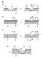
- the schematic diagram which shows three aspects of formation of the protective film of the segment form which concerns on this invention, and the groove part of a protective film.
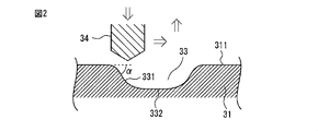
- the longitudinal cross-sectional view which shows an example which carries out the groove process to the base material by cutting.
- the top view which shows an example of the protective film which formed the groove
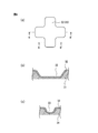
- the top view and longitudinal cross-sectional view which show an example of the pond which comprises a groove
- the protective film is a protective film having a segment structure in which a film is deposited on a base material, and after the groove processing is performed on the base material, as shown in FIG. Is deposited to form an interval between the segment protective films.
- the vertical cross-section of the part where the groove side and the bottom of the groove intersect is connected with a downward convex curve so that stress that breaks or breaks the film does not concentrate and the stress is easily propagated to the substrate side.
- the longitudinal section of the bottom of the groove is a downwardly convex curve or straight line.
- the portion (corner portion) where the groove side surface and the bottom of the groove intersect with each other is configured such that the longitudinal section is connected by a downwardly convex curve.
- the vertical cross-sectional shape of the bottom of the groove is configured to be a straight line or a downwardly convex curve (for example, approximating a part of an ellipse), and the vertical cross-sectional shape of the orthogonal grooves is, for example, U-shaped. Is selected.
- the shape of the end portion is the angle of the wall reaching the bottom of the groove, and the curved shape connected to the bottom follows the above-described shape.
- the ⁇ downwardly convex curve '' is a shape of a downwardly convex curve from the groove side surface to the bottom, from the groove side surface to the groove bottom, through the bottom of the groove to the opposite rising groove side surface.
- the connected portion is connected by a curve (R 1 ), the curvature of the curve is large near the wall (ie, the curvature radius is small and the curve is sharp), and the curvature is small at the center of the groove bottom (the curvature radius is small).
- the ideal is a line that is connected while the curvature changes one after another (temporarily) so that it is in a large (R 2 ) and gently curved state. This curve becomes part of an elliptic curve.
- FIG. 1D shows two Rs, namely, R 1 at the intersection of the groove side and bottom and R 2 at the center of the groove bottom.
- the vertical cross-sectional shape of the bottom of the groove is a straight line
- the portion connected from the groove side surface to the bottom portion is connected by a curve (R 1 ), and the vertical cross-sectional shape of the bottom portion of the extended portion is a straight line.
- the inclination angle ⁇ of the groove side surface from the base material surface to the bottom of the groove is preferably 60 degrees or less. is there. More preferably, ⁇ is 25 ⁇ 20 degrees.
- reference numeral 31 denotes a substrate
- 311 denotes a substrate surface
- 32 denotes a protective film
- 321 denotes a protective film surface
- 33 denotes a groove
- 331 denotes a groove inclined surface
- 332 denotes a groove bottom.
- ⁇ represents the inclination angle of the groove side surface from the substrate surface to the bottom of the groove.
- the distance from the horizontal surface (corresponding to the substrate surface or the protective film surface) to the groove side surface surface is sequentially measured using a laser microscope (for example, VK-9710 manufactured by Keyence Corporation). The inclination of the groove side surface can be measured.
- FIG. 2 is a longitudinal sectional view showing an example of grooving a base material by cutting, and ⁇ indicates the inclination angle of the groove side surface from the base material surface to the bottom of the groove.
- 31 is a base material
- 311 is a base material surface
- 33 is a groove
- 331 is an inclined surface of the groove
- 332 is a bottom portion of the groove
- 34 is a cutting tool.
- the base material 31 is moved downward while moving the cutting tool 34 in the lateral direction to be cut to a predetermined depth, an inclined surface is formed, and then the cutting tool 4 is moved to the predetermined position in the horizontal direction and then proceeds. By raising the direction as it is, another inclined surface of the groove side surface is formed.
- the depth direction (vertical direction in the figure) can be formed in the same manner.
- the shoulders of the two inclined surfaces are preferably processed so as to have a desired curvature as will be described later.
- a protective film is deposited on the base material 31 (not shown).
- the protective film is also deposited on the inclined surface 331 of the groove side surface and the bottom portion 332 of the groove, but the deposition rate is low with respect to the deposition rate on the substrate surface 311 and the film thickness is thinner than that. .
- a part of the stress applied to the surface of the protective film on which the outermost protective film is deposited may also be applied to this slope, but since it is not the purpose of receiving stress, the film thickness on the groove side surface and groove bottom is thin. Further, even without a film, there is no effect on the overall wear resistance improvement and low friction sliding.
- the grooving method can be used by laser processing, cutting processing, heating processing, grinding processing, plastic processing, electrical discharge processing, 3D processing, water jet processing, injection molding processing, casting processing, etching processing, or a combination thereof. Polishing can also be used to adjust the groove and surface roughness.
- various pretreatments can be performed on the base material in advance.
- nitriding treatment in which nitrogen is immersed in metal to harden the surface
- carburizing in which carbon is added to metal to harden the surface
- tempering after quenching and tempering steel to enhance toughness and diffusion and infiltration of chromium into metal
- chromizing for enhancing corrosion resistance and wear resistance
- phosphate treatment for forming a coating film such as zinc phosphate on the surface of steel to enhance corrosion resistance and adhesion.
- the laser is YAG laser (fundamental wave, second harmonic, third harmonic), CO 2 laser, argon laser, excimer laser (ArF, KrF), fiber laser, depending on the object to be machined and usage.
- YAG laser fundamental wave, second harmonic, third harmonic
- CO 2 laser argon laser
- excimer laser ArF, KrF
- fiber laser depending on the object to be machined and usage.
- Femtosecond laser, picosecond laser, etc. can be suitably used.
- the protective film is a carbon-based material (DLC, diamond, etc.)
- the crystal state changes at a temperature of 300 ° C. (° C.) or more, the graphite component increases, and the hardness may be reduced.
- the processing atmosphere is an oxidizing environment (O 2 gas, air, O 3 gas), CO 2 may be generated.
- a predetermined portion can be changed to graphite, carbon dioxide gas, or the like so that it can be easily removed.
- Cutting is a process that uses a cutting tool such as a micro-luter to cut the workpiece in the order from the surface to the inside. Milling, machining, multi-axis machining, jig borer, NC lathe, automatic lathe You can engrave the groove using a machine tool.
- a cutting tool such as a micro-luter
- Heat processing can use the heat that changes the protective film when processing the protective film, and by simply pressing a red-hot metal against the protective film surface, the heat affected part can be protected. Processing using changes in the composition of the film is also possible. This is particularly effective for carbon-based protective films such as DLC and diamond films.
- Grinding is a process that uses abrasive grains, and grinding machines, machining processes, grooving processes, and the like are performed. If you design and manufacture the tip of a grindstone or polishing tool, you can engrave a certain angle.
- Plastic processing is a processing method that uses the fact that the surface shape of the base material does not return when a material harder than the work piece, such as a die, blade, drawing die, or tool, is pressed against the other base material. Press processing, nanoimprint processing Single processing such as knurling or continuous processing is performed by moving the substrate side.
- Electric discharge machining is metal processing that uses fine arc discharge melting between the substrate and the mold when the substrate is energized. Can be engraved.
- 3D processing it is possible to deposit a mask soot using resin or metal by a 3D printer, and it is possible to change the height of the soot characteristically.
- Normally known 3D printers form while depositing resin and metal, but basically a printer head that discharges a bed that moves in the YZ axis direction and a resin that moves in the X axis, or a laser that melts metal powder Has a mechanism that moves while synchronizing. If this function is combined with a mechanism for rotating a workpiece (workpiece), 3D printing can be performed on a three-dimensional object.
- an element for carving a substrate such as ink containing a corrosive substance is printed, and after a predetermined time, a portion to be corroded is carved.
- a portion to be corroded is carved.
- it can be engraved in separate parts.
- the engraved groove portion comparable to the ridge is continuous, but according to this method, since the mask is not used, an independent groove (pond-shaped depression) can be created. It is also possible to process a large area in a certain time.
- Water jet machining is a machining method in which a workpiece is cut or engraved by introducing an abrasive into water and spraying it at a high pressure of about 2000 atm.
- the injection molding process is a processing method in which a heat-melted resin or the like is injected and injected into a mold and cooled and solidified to obtain a molded product having a desired groove.
- a so-called lost wax method in which a prototype is produced with wax, the periphery is covered with foundry sand, and the wax is melted and removed to pour metal into the formed cavity can be suitably used.
- Etching is engraving with a corrosive solution that passes through a mask, and various patterns of masks can be combined to create a pattern engraving that allows multiple simultaneous processing by setting multiple masks at the same time.
- Engraving depth can be changed by contact time with corrosive liquid. It is also possible to control the etching rate by making a direct connection with an external electrode using a corrosive solution as an electrolyte (electropolishing).
- the groove is processed so as to have a size and shape corresponding to the segment interval part.
- laser processing will be mainly described.
- the width (size), depth, etc. of the groove can be easily controlled.
- the laser processing speed can easily achieve about 300 mm / second.
- the cutting speed with a micro-luter which is a general mechanical cutting tool, is about 0.1 mm / second, and the laser processing speed is 3000 times that.
- the lower limit of the groove width by laser is usually about 15 ⁇ m by picosecond laser processing.
- the lower limit of the groove width in a micro-luter which is a general mechanical cutting tool is about 70 ⁇ m. That is, the laser can process a finer groove.
- the upper limit of the groove width can be expanded infinitely by repeating the groove processing while shifting the laser.
- the depth of the groove can be arbitrarily adjusted as long as it is about 1 ⁇ m or more.
- the depth of the groove can be adjusted by repeating the groove processing.
- Groove processing can be arbitrarily changed if the mesh (interval between grooves) is about 2 ⁇ m or more, and can be set so that the fine segment structure and the large segment structure gradually change.
- the groove processing pattern can be freely set, that is, the radius of curvature of the groove cutting curve can be arbitrarily set. Therefore, since different segment patterns can be applied to one base material, it is possible to obtain a protective film having an optimum segment structure according to the application.
- the fact that the groove processing pattern can be set freely means that marking and naming can be performed using a segment structure protective film. Furthermore, by changing the position, size, and range of the segment structure, the width and bending of the groove can be freely controlled.
- the groove can be a flow path or a closed groove (pond). It can be easily used as an oil pit.
- the laser is easily accessible because it is in optical contact with the workpiece.
- Lasers can be mirror-reflected or irradiated with an optical fiber, and processing with a higher degree of freedom is possible.
- it is difficult to be restricted by the surface shape of the workpiece.
- a protective film is deposited to form an interval between the segment protective films.
- the width of the groove is selected from the range of the interval between the adjacent segments of 0.1 ⁇ m to 1 mm.
- the depth of the groove is selected from a range of about 1 ⁇ m to 2 mm. Since it is difficult at present to uniformly introduce grooves of 1 ⁇ m or less with accuracy of groove processing using a laser, the lower limit is about 1 ⁇ m.
- the protective film has a vertical cross section at the bottom where the groove side and the bottom of the groove intersect so that stress that breaks or breaks the film does not concentrate and the stress is easily propagated to the substrate side. They are connected by a convex curve, and the longitudinal section of the bottom of the groove is configured to be a downward convex curve or a straight line.
- a groove depth corresponding to the film thickness that is, only a groove depth of several nanometers to several hundred micrometers can be obtained.
- a groove having a depth of about 1 mm can be easily produced.
- the thickness of the protective film to be deposited is usually 1 nm to 200 ⁇ m, and the depth of the groove is sufficiently deep, about 1 ⁇ m to 2 mm.
- the segment form is obtained as an effect of the outermost surface related to wear resistance, slidability, etc., such as contact and stress.
- the film thickness is relatively thin with respect to the outermost surface.
- the film When (groove depth ⁇ groove width) is large, the film can be divided at the groove side or bottom. Thereby, the protective film of a segment form is obtained.
- the depth of the groove for dividing the film is usually at least 5 times the thickness of the desired protective film, preferably at least 20 times, more preferably at least 50 times, more preferably at least 100 times, more preferably 150 times or more.
- Residue made by laser processing may occur in a shape protruding from the substrate surface. That is, so-called burrs may be formed on the periphery of the groove. It is preferable to remove this burr if necessary. The removal of burrs can be carried out by an appropriate physical method without damaging the substrate.
- ⁇ Laser can be used again as a method of removing burrs.
- the burr part is heated and melted and deformed, and the shoulder part of the groove (the side where the surface of the substrate and the side surface of the groove meet and its vicinity) It becomes gentle.
- the shoulder portion of the groove can be bent with a radius of curvature larger than the thickness of the protective film. Until the shape of the shoulder portion of the groove becomes a desired shape, the focus (defocus), output, offset amount, number of reciprocations, and the like of the laser can be appropriately adjusted.
- an appropriate tool and method can be used according to the material of the base material and the desired groove size / shape, for example, sandpaper polishing, buffing, fluid polishing, magnetic polishing, etc. Polishing, sand blasting, blasting with solid carbon dioxide powder, grinding with a rotating grindstone, etching such as isotropic dry etching, electropolishing using an electrolyte solution, and the like can also be used. These methods for removing burrs may be used in combination. In particular, by deburring with a method other than laser after deburring with a laser, the radius of curvature of the shoulder can be more accurately aligned, which is advantageous in terms of quality control.
- the substrate used in the present invention is not particularly limited.
- a metal such as an aluminum alloy, a magnesium alloy, a copper alloy, a titanium alloy, a heat-resistant alloy, a stainless alloy, a tungsten alloy, or steel; a polymer substrate such as a plastic; Rubber, ceramic, carbon-based materials such as CFRP, and composite materials thereof can be used, and can be appropriately selected depending on the purpose.
- the substrate surface on which the protective film is deposited may form a three-dimensional curved surface.
- the three-dimensional curved surface is a surface made by plastic working such as press working, a surface made by cutting, a surface of a three-dimensional object such as injection molding, die casting, MIM (Metal Injection Mold), sintering, firing, In particular, it is a curved surface.
- the shape of the segment protective film is not particularly limited, and a polygon such as a triangle and a quadrangle, a circle, and the like can be appropriately selected.
- the present invention can be applied to a soccer ball-shaped segment protective film in which a pentagon and a hexagon are combined.
- the present invention can also be applied to a spherical segment protective film in which a central portion of a triangle is projected (more than a side portion).
- the present invention can be applied to a segment protective film partitioned by grooves having different widths and depths depending on places.
- the size of these segment protective films is usually selected from one side or an outer diameter of 1 ⁇ m to 3 mm.
- the interval between adjacent segment protective films is usually 0.1 ⁇ m to 1 mm.
- the thickness of the segment protective film is usually 1 nm to 200 ⁇ m.
- planar shape of the groove may be a grid, stripe, pond, or a combination of these, which may be a channel or a closed pond, Can be used as an oil reservoir. Further, by introducing a fluid lubricant or a solid lubricant into these grooves, the grooves can be made into a fluid or solid lubricant layer.
- FIG. 3 is a plan view showing an example of a protective film in which grooves of various shapes are formed on a base material.
- 31 is a base material
- 32 is a protective film
- 33 is various types formed on the protective film 32.
- the groove of the shape (pond shape, lattice shape, stripe shape) is shown.
- FIG. 4 shows a plan view (a) showing an example of a pond constituting the groove in FIG. 3, and its A-A ′ cut surface (b) and B-B ′ cut surface (c).
- the protective film includes a diamond-like carbon film, a diamond film, a BN film, a W 2 C film, a CrN film, a HfN film, a VN film, a TiN film, a TiCN film, an Al 2 O 3 film, and a ZnO film. , SiO 2 films, and combinations thereof.
- the deposition method of the protective film is preferably a vapor phase deposition method, for example, a plasma CVD method using a direct current, an alternating current or a high frequency as a power source, or a sputtering method such as magnetron sputtering or ion beam sputtering. PVD (Physical Vapor Deposition) can also be used to achieve the same effect.
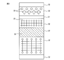
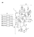
- FIG. 5 shows a basic configuration of an example of a plasma CVD film forming apparatus.
- Chamber 5 exhaust system 10 (rotary pump 11, turbo molecular pump 12, vacuum gauge 13, exhaust valve 14, etc.), gas introduction system 15 (Ar, C 2 H 2 , Si (CH 3 ) 4 ), H 2 , O 2 , N 2 , CH 4 , CF 4, etc. gas introduction system and flow rate adjustment valve) and power supply system 20 (main power supply 16, substrate heating power supply 17, fine particle capture filter power supply 18, surplus electron collection power supply 19, etc.)
- summary of the apparatus provided with this is shown.
- a substrate is connected to the cathode electrode in the chamber of the apparatus, and the substrate is grooved.
- the inside of the chamber is evacuated by a vacuum evacuation mechanism, and then a plasma gas source Ar, Si (CH 3 ) 4 , C 2 H 2, etc. is supplied, a pulse voltage is applied by a pulse power source, and the plasma gas The source is turned into plasma.
- Plasmaized gas is deposited on the substrate to form a film, but the groove depth is sufficiently deep with respect to the film thickness, so the film is divided by the groove or relatively thin relative to the surface.
- the function as a protective film is reduced, and at the same time, even if a film is attached to the bottom of an oblique wall or groove, the function as a mechanical protective film is reduced, but the protection of the segment form with improved chemical stability A membrane is obtained.
- the film formation rate in the groove can be adjusted by appropriately selecting the atmosphere during laser groove processing. Specifically, when an oxidizing atmosphere gas such as oxygen or ozone is used during laser groove processing, it becomes easy to oxidize the surface to be processed. Oxides generally have low conductivity, and conductivity to the groove oxidized during film formation is suppressed, so that film formation in the groove is suppressed. For this reason, it becomes easy to form a protective film in the location without a groove
- an oxidizing atmosphere gas such as oxygen or ozone
- the atmosphere at the time of laser groove processing may be selected from an inert gas such as argon or nitrogen gas. Thereby, it is also possible to suppress oxidation of the surface of the groove portion during groove processing.
- the deposited protective film is preferably capable of imparting wear resistance, such as diamond film, diamond-like carbon film, BN film, W 2 C film, CrN film, HfN film, VN film, TiN film, Any of a TiCN film, an Al 2 O 3 film, a ZnO film, a SiO 2 film, or a combination thereof may be included. These film thicknesses are usually selected from 1 nm to 200 ⁇ m.
- the protective film may be selected from the group consisting of a metal plating film, an alumite film, a resin film, and combinations thereof.
- the formation of these films can be performed by a conventional method.
- a metal plating film a wet method such as nickel plating or chrome plating is preferable.
- alumite film a wet method using anodization is preferable.
- the resin film a fluororesin coating is used. Is preferred.
- the thickness of these protective films is usually selected from 50 nm to 500 ⁇ m.
- the protective film may be divided by the groove or may be continuous.
- the protective film is a protective film having a segment structure in which a film is deposited on a substrate, and the protective film 32 is formed on the substrate 31 as shown in FIG. After deposition (usually, the substrate surface 311 and the protective film surface 321 are parallel), a groove is formed in the protective film 32 to form an interval between the segment protective films.
- the vertical cross section of the part where the groove side and the bottom of the groove intersect is connected with a downward convex curve so that stress that breaks or breaks the film does not concentrate and the stress is easily propagated to the substrate side.
- the longitudinal section of the bottom of the groove is configured to be a downwardly convex curve or straight line.
- the inclination angle ⁇ of the groove side surface from the protective film surface 321 to the groove bottom 332 is 60 degrees or less. With such a configuration, it is possible to easily propagate the stress to the substrate side without concentrating stress that damages or breaks the film. More preferably, ⁇ is 25 ⁇ 20 degrees.
- the surface of the protective film is a curved surface, the angle from the tangent at the corresponding position is obtained.
- a protective film having a segment structure in which a film is deposited on a substrate 31, and a protective film 32 is deposited on the substrate 31 (see FIG. Usually, the substrate surface 311 and the protective film surface 321 are parallel to each other), and then grooves are formed in the protective film 32 and the substrate 31 to form an interval between the segment protective films.
- the vertical cross section of the part where the groove side and the bottom of the groove intersect is connected with a downward convex curve so that stress that breaks or breaks the film does not concentrate and the stress is easily propagated to the substrate side.
- the longitudinal section of the bottom of the groove is configured to be a downwardly convex curve or straight line.
- the inclination angle ⁇ of the groove side surface from the protective film surface 321 to the groove bottom 332 is 60 degrees or less. More preferably, ⁇ is 25 ⁇ 20 degrees.
- the surface of the protective film is a curved surface, the angle from the tangent at the corresponding position is obtained.
- a grooved substrate which does not concentrate stresses that break or break the substrate or the film formed on the surface of the substrate.
- the longitudinal cross section of the portion where the groove side surface and the bottom of the groove intersect with each other is connected with a downward convex curve, and the longitudinal cross section of the bottom of the groove is a downward convex curve or a straight line.
- the downward inclination angle ⁇ of the groove side surface from the substrate surface to the bottom of the groove is 60 degrees or less. More preferably, ⁇ is 25 ⁇ 20 degrees.
- the groove processing itself is selected from laser processing, cutting processing, heating processing, grinding processing, plastic processing, electrical discharge processing, 3D processing, water jet processing, injection molding processing, casting processing, etching processing, or a combination thereof. obtain.
- the planar shape of the groove may be preferably selected from a grid shape, a stripe shape, a pond shape, or a combination thereof, and the vertical cross-sectional shape of the bottom portion of the groove is preferably a straight line or a downward convex curve. is there.
- the width and depth of the groove are also as described above.
- the base material of the present invention is suitable for forming the above-described segment form of the protective film on the base material, due to the external stress that is the stress entering from the surface of the protective film and the internal stress that is the stress given from the inside, It is possible to prevent the protective film from being broken or damaged, and to obtain a protective film that is stable against external stress and internal stress. Further, the base material itself of the present invention can be controlled according to the location of the surface strength by combining the grooves and changing the strength partially.
Landscapes
- Chemical & Material Sciences (AREA)
- Engineering & Computer Science (AREA)
- Mechanical Engineering (AREA)
- Chemical Kinetics & Catalysis (AREA)
- Materials Engineering (AREA)
- Metallurgy (AREA)
- Organic Chemistry (AREA)
- General Chemical & Material Sciences (AREA)
- Inorganic Chemistry (AREA)
- Physics & Mathematics (AREA)
- Optics & Photonics (AREA)
- Thermal Sciences (AREA)
- Laser Beam Processing (AREA)
- Chemical Vapour Deposition (AREA)
- Cutting Tools, Boring Holders, And Turrets (AREA)
- Physical Vapour Deposition (AREA)
- Diaphragms And Bellows (AREA)
Priority Applications (3)
| Application Number | Priority Date | Filing Date | Title |
|---|---|---|---|
| CN201680021998.0A CN107532293A (zh) | 2015-04-16 | 2016-04-05 | 保护膜及其制造方法 |
| EP16779952.7A EP3284845A4 (en) | 2015-04-16 | 2016-04-05 | Protective film and method for producing same |
| US15/563,504 US20180087149A1 (en) | 2015-04-16 | 2016-04-05 | Protective film and method for producing same |
Applications Claiming Priority (2)
| Application Number | Priority Date | Filing Date | Title |
|---|---|---|---|
| JP2015-084478 | 2015-04-16 | ||
| JP2015084478A JP6616094B2 (ja) | 2015-04-16 | 2015-04-16 | 保護膜の製造方法 |
Publications (1)
| Publication Number | Publication Date |
|---|---|
| WO2016167161A1 true WO2016167161A1 (ja) | 2016-10-20 |
Family
ID=57125928
Family Applications (1)
| Application Number | Title | Priority Date | Filing Date |
|---|---|---|---|
| PCT/JP2016/061168 WO2016167161A1 (ja) | 2015-04-16 | 2016-04-05 | 保護膜およびその製造方法 |
Country Status (6)
Cited By (1)
| Publication number | Priority date | Publication date | Assignee | Title |
|---|---|---|---|---|
| WO2022138849A1 (ja) * | 2020-12-24 | 2022-06-30 | 日本アイ・ティ・エフ株式会社 | 硬質炭素膜とその成膜方法 |
Families Citing this family (5)
| Publication number | Priority date | Publication date | Assignee | Title |
|---|---|---|---|---|
| CN109070240B (zh) * | 2016-04-25 | 2020-04-24 | 京瓷株式会社 | 刀片以及切削工具 |
| EP3357615B1 (en) * | 2016-12-20 | 2023-01-18 | Sumitomo Electric Hardmetal Corp. | Cutting tool and manufacturing method thereof |
| WO2021020007A1 (ja) * | 2019-08-01 | 2021-02-04 | 住友電工ハードメタル株式会社 | 切削工具の製造方法および切削工具 |
| EP4477337A4 (en) * | 2022-02-07 | 2025-04-23 | Nissan Motor Co., Ltd. | METAL POWDER PRODUCTION PROCESS |
| CN115446961B (zh) * | 2022-09-29 | 2024-04-16 | 重庆市欧华陶瓷(集团)有限责任公司 | 一种抛釉瓷砖的镀金设备及其工艺 |
Citations (8)
| Publication number | Priority date | Publication date | Assignee | Title |
|---|---|---|---|---|
| JPH01185553A (ja) * | 1988-01-19 | 1989-07-25 | Canon Inc | 表面加工されたレーザー用電子写真感光体用基体 |
| JPH07251301A (ja) * | 1994-03-01 | 1995-10-03 | Saint Gobain Norton Ind Ceramics Corp | Cvdダイヤモンドの切削工具 |
| JP2003147525A (ja) * | 2001-11-07 | 2003-05-21 | Rikogaku Shinkokai | 保護膜 |
| JP3448884B2 (ja) * | 1992-12-15 | 2003-09-22 | 日本精工株式会社 | 人工ダイヤモンド被覆材 |
| JP2007118139A (ja) * | 2005-10-28 | 2007-05-17 | Kyocera Corp | 表面被覆切削工具 |
| JP2010007112A (ja) * | 2008-06-25 | 2010-01-14 | Hitachi Chem Co Ltd | セグメント形態の無機材料膜を有する部材及びセグメント形態の無機材料膜の製造法 |
| WO2011030926A1 (ja) * | 2009-09-11 | 2011-03-17 | 株式会社iMott | 保護膜およびそれを作製する方法 |
| JP2012188698A (ja) * | 2011-03-10 | 2012-10-04 | Imott Inc | 保護膜およびそれを作製する方法 |
Family Cites Families (8)
| Publication number | Priority date | Publication date | Assignee | Title |
|---|---|---|---|---|
| DE3634708A1 (de) * | 1986-10-11 | 1988-04-28 | Goetze Ag | Gleitender reibung ausgesetztes maschinenteil, wie insbesonder kolbenring |
| US5435889A (en) * | 1988-11-29 | 1995-07-25 | Chromalloy Gas Turbine Corporation | Preparation and coating of composite surfaces |
| WO2003091474A1 (de) * | 2002-04-25 | 2003-11-06 | Unaxis Balzers Ag | Strukturiertes schichtsystem |
| CN101557927B (zh) * | 2006-12-27 | 2014-10-22 | 日立化成株式会社 | 凹版和使用该凹版的带有导体层图形的基材 |
| JP5052638B2 (ja) * | 2010-03-17 | 2012-10-17 | Sppテクノロジーズ株式会社 | 成膜方法 |
| JP5661523B2 (ja) * | 2011-03-18 | 2015-01-28 | 東京エレクトロン株式会社 | 成膜方法及び成膜装置 |
| US9617654B2 (en) * | 2012-12-21 | 2017-04-11 | Exxonmobil Research And Engineering Company | Low friction coatings with improved abrasion and wear properties and methods of making |
| KR101648544B1 (ko) * | 2013-02-12 | 2016-08-17 | 가부시키가이샤 씽크. 라보라토리 | 연속 도금용 패터닝 롤 및 그 제조 방법 |
-
2015
- 2015-04-16 JP JP2015084478A patent/JP6616094B2/ja active Active
-
2016
- 2016-04-05 WO PCT/JP2016/061168 patent/WO2016167161A1/ja active Application Filing
- 2016-04-05 CN CN201680021998.0A patent/CN107532293A/zh active Pending
- 2016-04-05 EP EP16779952.7A patent/EP3284845A4/en not_active Withdrawn
- 2016-04-05 US US15/563,504 patent/US20180087149A1/en not_active Abandoned
- 2016-04-14 TW TW105111637A patent/TWI619830B/zh not_active IP Right Cessation
Patent Citations (8)
| Publication number | Priority date | Publication date | Assignee | Title |
|---|---|---|---|---|
| JPH01185553A (ja) * | 1988-01-19 | 1989-07-25 | Canon Inc | 表面加工されたレーザー用電子写真感光体用基体 |
| JP3448884B2 (ja) * | 1992-12-15 | 2003-09-22 | 日本精工株式会社 | 人工ダイヤモンド被覆材 |
| JPH07251301A (ja) * | 1994-03-01 | 1995-10-03 | Saint Gobain Norton Ind Ceramics Corp | Cvdダイヤモンドの切削工具 |
| JP2003147525A (ja) * | 2001-11-07 | 2003-05-21 | Rikogaku Shinkokai | 保護膜 |
| JP2007118139A (ja) * | 2005-10-28 | 2007-05-17 | Kyocera Corp | 表面被覆切削工具 |
| JP2010007112A (ja) * | 2008-06-25 | 2010-01-14 | Hitachi Chem Co Ltd | セグメント形態の無機材料膜を有する部材及びセグメント形態の無機材料膜の製造法 |
| WO2011030926A1 (ja) * | 2009-09-11 | 2011-03-17 | 株式会社iMott | 保護膜およびそれを作製する方法 |
| JP2012188698A (ja) * | 2011-03-10 | 2012-10-04 | Imott Inc | 保護膜およびそれを作製する方法 |
Non-Patent Citations (1)
| Title |
|---|
| See also references of EP3284845A4 * |
Cited By (4)
| Publication number | Priority date | Publication date | Assignee | Title |
|---|---|---|---|---|
| WO2022138849A1 (ja) * | 2020-12-24 | 2022-06-30 | 日本アイ・ティ・エフ株式会社 | 硬質炭素膜とその成膜方法 |
| JP2022100954A (ja) * | 2020-12-24 | 2022-07-06 | 日本アイ・ティ・エフ株式会社 | 硬質炭素膜とその成膜方法 |
| JP2024052914A (ja) * | 2020-12-24 | 2024-04-12 | 日本アイ・ティ・エフ株式会社 | 硬質炭素膜とその成膜方法 |
| JP7731532B2 (ja) | 2020-12-24 | 2025-09-01 | 日本アイ・ティ・エフ株式会社 | 硬質炭素膜とその成膜方法 |
Also Published As
| Publication number | Publication date |
|---|---|
| CN107532293A (zh) | 2018-01-02 |
| US20180087149A1 (en) | 2018-03-29 |
| JP2016204684A (ja) | 2016-12-08 |
| EP3284845A1 (en) | 2018-02-21 |
| JP6616094B2 (ja) | 2019-12-04 |
| TWI619830B (zh) | 2018-04-01 |
| EP3284845A4 (en) | 2018-10-10 |
| TW201702415A (zh) | 2017-01-16 |
Similar Documents
| Publication | Publication Date | Title |
|---|---|---|
| WO2016167161A1 (ja) | 保護膜およびその製造方法 | |
| Wu et al. | Tribological characteristics and advanced processing methods of textured surfaces: a review | |
| Coblas et al. | Manufacturing textured surfaces: State of art and recent developments | |
| CN108274123B (zh) | 一种用于激光增材构件内壁的增材-抛光一体化加工方法 | |
| JP6650025B2 (ja) | 機械加工工具の刃先部構造及びその表面処理方法 | |
| Brinksmeier et al. | Advances in precision machining of steel | |
| KR20150095695A (ko) | 코팅된 절삭 공구 및 코팅된 절삭 공구의 제조 방법 | |
| CN110744201A (zh) | 一种微织构刀具的制备方法及微织构刀具 | |
| CN109890555B (zh) | 在金刚石的表面形成精细周期性结构的槽的方法 | |
| CN114101501A (zh) | 一种超声冲击与微织构加工复合处理的冲压模具及方法 | |
| JP5721481B2 (ja) | 保護膜の製造方法 | |
| JP2008173693A (ja) | 鏡面加工方法 | |
| JP4749073B2 (ja) | 金型及びその製造方法 | |
| JP4526325B2 (ja) | 電解液ジェット加工方法 | |
| Liu et al. | Development of high-performance polycrystalline CVD diamond-coated cutting tools using femtosecond lasers | |
| JPH0584663A (ja) | ウオータージエツト切断機用ノズル | |
| JPS63108930A (ja) | 金型の製造方法 | |
| JP2017056499A (ja) | 超硬工具及びその製造方法 | |
| Tengjiao | Precision Machining of Hard-to-Cut Materials: Current Status and Future Directions. | |
| Jarosz | A review of the recent investigations regarding texturized cutting tools | |
| JP4117681B2 (ja) | 金型、プレス加工用ポンチ、金型の製造方法及び成形加工方法 | |
| JP2016036852A (ja) | 微小ディンプル形成方法及び該形成方法により形成された微小ディンプルを備えた部材 | |
| JP2016140868A (ja) | 摺動部材のテクスチャ加工方法並びに摺動部材 | |
| JP2017056498A (ja) | 超硬工具及びその製造方法 | |
| Klocke et al. | Diamond turning of aspheric steel molds for optics replication |
Legal Events
| Date | Code | Title | Description |
|---|---|---|---|
| 121 | Ep: the epo has been informed by wipo that ep was designated in this application |
Ref document number: 16779952 Country of ref document: EP Kind code of ref document: A1 |
|
| DPE1 | Request for preliminary examination filed after expiration of 19th month from priority date (pct application filed from 20040101) | ||
| WWE | Wipo information: entry into national phase |
Ref document number: 15563504 Country of ref document: US |
|
| NENP | Non-entry into the national phase |
Ref country code: DE |