WO2016167125A1 - 端子および端子付き電線 - Google Patents
端子および端子付き電線 Download PDFInfo
- Publication number
- WO2016167125A1 WO2016167125A1 PCT/JP2016/060343 JP2016060343W WO2016167125A1 WO 2016167125 A1 WO2016167125 A1 WO 2016167125A1 JP 2016060343 W JP2016060343 W JP 2016060343W WO 2016167125 A1 WO2016167125 A1 WO 2016167125A1
- Authority
- WO
- WIPO (PCT)
- Prior art keywords
- terminal
- electric wire
- wire
- insulation
- barrel
- Prior art date
- Legal status (The legal status is an assumption and is not a legal conclusion. Google has not performed a legal analysis and makes no representation as to the accuracy of the status listed.)
- Ceased
Links
Images



Classifications
-
- H—ELECTRICITY
- H01—ELECTRIC ELEMENTS
- H01R—ELECTRICALLY-CONDUCTIVE CONNECTIONS; STRUCTURAL ASSOCIATIONS OF A PLURALITY OF MUTUALLY-INSULATED ELECTRICAL CONNECTING ELEMENTS; COUPLING DEVICES; CURRENT COLLECTORS
- H01R4/00—Electrically-conductive connections between two or more conductive members in direct contact, i.e. touching one another; Means for effecting or maintaining such contact; Electrically-conductive connections having two or more spaced connecting locations for conductors and using contact members penetrating insulation
- H01R4/10—Electrically-conductive connections between two or more conductive members in direct contact, i.e. touching one another; Means for effecting or maintaining such contact; Electrically-conductive connections having two or more spaced connecting locations for conductors and using contact members penetrating insulation effected solely by twisting, wrapping, bending, crimping, or other permanent deformation
- H01R4/18—Electrically-conductive connections between two or more conductive members in direct contact, i.e. touching one another; Means for effecting or maintaining such contact; Electrically-conductive connections having two or more spaced connecting locations for conductors and using contact members penetrating insulation effected solely by twisting, wrapping, bending, crimping, or other permanent deformation by crimping
- H01R4/183—Electrically-conductive connections between two or more conductive members in direct contact, i.e. touching one another; Means for effecting or maintaining such contact; Electrically-conductive connections having two or more spaced connecting locations for conductors and using contact members penetrating insulation effected solely by twisting, wrapping, bending, crimping, or other permanent deformation by crimping for cylindrical elongated bodies, e.g. cables having circular cross-section
- H01R4/184—Electrically-conductive connections between two or more conductive members in direct contact, i.e. touching one another; Means for effecting or maintaining such contact; Electrically-conductive connections having two or more spaced connecting locations for conductors and using contact members penetrating insulation effected solely by twisting, wrapping, bending, crimping, or other permanent deformation by crimping for cylindrical elongated bodies, e.g. cables having circular cross-section comprising a U-shaped wire-receiving portion
- H01R4/185—Electrically-conductive connections between two or more conductive members in direct contact, i.e. touching one another; Means for effecting or maintaining such contact; Electrically-conductive connections having two or more spaced connecting locations for conductors and using contact members penetrating insulation effected solely by twisting, wrapping, bending, crimping, or other permanent deformation by crimping for cylindrical elongated bodies, e.g. cables having circular cross-section comprising a U-shaped wire-receiving portion combined with a U-shaped insulation-receiving portion
-
- H—ELECTRICITY
- H01—ELECTRIC ELEMENTS
- H01R—ELECTRICALLY-CONDUCTIVE CONNECTIONS; STRUCTURAL ASSOCIATIONS OF A PLURALITY OF MUTUALLY-INSULATED ELECTRICAL CONNECTING ELEMENTS; COUPLING DEVICES; CURRENT COLLECTORS
- H01R4/00—Electrically-conductive connections between two or more conductive members in direct contact, i.e. touching one another; Means for effecting or maintaining such contact; Electrically-conductive connections having two or more spaced connecting locations for conductors and using contact members penetrating insulation
- H01R4/10—Electrically-conductive connections between two or more conductive members in direct contact, i.e. touching one another; Means for effecting or maintaining such contact; Electrically-conductive connections having two or more spaced connecting locations for conductors and using contact members penetrating insulation effected solely by twisting, wrapping, bending, crimping, or other permanent deformation
- H01R4/18—Electrically-conductive connections between two or more conductive members in direct contact, i.e. touching one another; Means for effecting or maintaining such contact; Electrically-conductive connections having two or more spaced connecting locations for conductors and using contact members penetrating insulation effected solely by twisting, wrapping, bending, crimping, or other permanent deformation by crimping
- H01R4/188—Electrically-conductive connections between two or more conductive members in direct contact, i.e. touching one another; Means for effecting or maintaining such contact; Electrically-conductive connections having two or more spaced connecting locations for conductors and using contact members penetrating insulation effected solely by twisting, wrapping, bending, crimping, or other permanent deformation by crimping having an uneven wire-receiving surface to improve the contact
-
- H—ELECTRICITY
- H01—ELECTRIC ELEMENTS
- H01R—ELECTRICALLY-CONDUCTIVE CONNECTIONS; STRUCTURAL ASSOCIATIONS OF A PLURALITY OF MUTUALLY-INSULATED ELECTRICAL CONNECTING ELEMENTS; COUPLING DEVICES; CURRENT COLLECTORS
- H01R4/00—Electrically-conductive connections between two or more conductive members in direct contact, i.e. touching one another; Means for effecting or maintaining such contact; Electrically-conductive connections having two or more spaced connecting locations for conductors and using contact members penetrating insulation
- H01R4/58—Electrically-conductive connections between two or more conductive members in direct contact, i.e. touching one another; Means for effecting or maintaining such contact; Electrically-conductive connections having two or more spaced connecting locations for conductors and using contact members penetrating insulation characterised by the form or material of the contacting members
- H01R4/62—Connections between conductors of different materials; Connections between or with aluminium or steel-core aluminium conductors
Definitions
- the technology disclosed in this specification relates to a terminal and an electric wire with a terminal.
- An aluminum electric wire has a structure in which a core wire composed of a stranded wire formed by twisting a plurality of aluminum strands, for example, is covered with an insulation coating, and when a harness is formed, generally, a terminal is connected to the end of the electric wire.
- the end of the insulation coating of the aluminum electric wire is peeled off to expose the end of the core wire, and the wire barrel (electric wire connecting portion) provided on the terminal is crimped to the exposed end of the core wire. Then, an insulation barrel provided behind the wire barrel is pressure-bonded to the terminal of the remaining insulation coating.
- an aluminum electric wire having a smaller diameter than the conventional one has been manufactured.
- a small-diameter aluminum electric wire has low impact strength, and when a large impact is applied to the electric wire in a state where it is connected to the terminal, the portion crimped to the wire barrel is relatively easily disconnected. .
- the technology disclosed in the present specification has been conceived in view of the above-described problems, and provides a terminal and a terminal-attached electric wire having high holding force of a crimping piece to be crimped to an outer peripheral surface of an insulating coating. To do.
- the technique disclosed in this specification is a terminal connected to a terminal of an aluminum electric wire whose core wire is covered with an insulating coating, and is formed to extend in a direction intersecting with a longitudinal direction of the aluminum electric wire, and the insulating coating A pair of pressure-bonding pieces that are pressure-bonded to the outer peripheral surface, and the pair of pressure-bonding pieces are abutted with each other facing each other in a state where they are pressure-bonded to the insulating coating.
- the technology disclosed in this specification is an electric wire with a terminal, and includes an aluminum electric wire whose core wire is covered with an insulating coating, and the terminal connected to the aluminum electric wire.
- tip part are faced
- the inner edge portion arranged on the insulating coating side at the tip portion of the terminal may be an inclined portion that is obliquely cut out toward the tip of the crimping piece.
- the insulation coating When the crimping piece is crimped with a strong force against the insulation coating, the insulation coating may be bitten while being pushed between the tip portions of the pair of crimping pieces in the process of crimping. As a result, the portion that is likely to be bitten is easily released into a mountain-shaped region surrounded by the pair of inclined portions, and biting can be avoided.
- This embodiment has illustrated the electric wire 30 with a terminal arranged, for example in a vehicle, and this electric wire 30 with a terminal is connected to the female terminal 10 and the female terminal 10, and is aluminum pulled out back from the female terminal 10.
- the electric wire 20 is provided (see FIG. 1).
- the left side in FIG. 1 is the front side
- the right side is the rear side
- the upper side is the upper side
- the lower side is the lower side.
- the lower right in FIG. 2 is the left and the upper left is the right.
- the aluminum electric wire 20 has a structure in which a core wire 21 is formed by a stranded wire formed by twisting a plurality of strands made of aluminum or aluminum alloy, and the core wire 21 is covered with an insulating coating 22 made of synthetic resin.
- the insulation coating 22 of the terminal is peeled off, and the core wire 21 is exposed forward from the insulation coating 22, and the female terminal 10 is connected to this terminal.
- the female terminal 10 is formed by punching a base material made of a copper alloy and bending it. As shown in FIG. 1, the wire connected to the terminal connecting portion 11 and the core wire 21 of the aluminum electric wire 20. It has the barrel 12, the insulation barrel 14 crimped
- the terminal connection portion 11 is formed in a box shape having a rectangular tube shape, and a male terminal tab (not shown) is inserted therein to be electrically connected.
- the wire barrel 12 is of an open barrel type, and as shown in FIG. 2, a pair of wire barrel pieces 12B extending from side to side rise from the left and right side edges of the bottom plate portion 12A. These wire barrel pieces 12B are crimped and electrically connected to the core wire 21 by being caulked inwardly with respect to the core wire 21 exposed from the insulating coating 22 at the front end portion of the aluminum electric wire 20.
- the insulation barrel 14 is also of an open barrel type, and is provided behind the wire barrel 12 with the connecting portion 13 interposed therebetween, and is a pair of insulation barrel pieces of a substantially rectangular shape having the same shape and the same size.
- 14B (an example of a crimping piece) extends from the left and right side edges of the bottom plate portion 14A at positions that are symmetrical to each other and rises up so as to face each other.
- the pair of insulation barrel pieces 14 ⁇ / b> B are configured to extend in the left-right direction intersecting the longitudinal direction (front-rear direction) of the aluminum electric wire 20.
- the pair of insulation barrel pieces 14B are wound around the outer periphery of the insulating coating 22 of the aluminum electric wire 20 placed on the bottom plate portion 14A, and are crimped in the radial direction against the outer peripheral surface of the insulating coating 22. Yes.
- the tip portions 14 ⁇ / b> C having a flat surface are opposed to each other and are abutted against each other.
- the pair of insulation barrel pieces 14B is set in advance to have a length dimension that allows the insulation coating 22 to be compressed at a desired compression rate in a state where the insulation barrel pieces 14B are crimped to the insulation coating 22.
- the corner portion of the inner edge portion arranged on the insulating coating 22 side in the state where it is crimped to the insulating coating 22 is notched obliquely toward the tip end so as to extend along the longitudinal direction (front-rear direction), and the notched portion is an inclined portion 14D.
- the inclined portion 14D has a shape inclined toward the tip side of the insulation barrel piece 14B.
- the aluminum wire 20 in which the insulation coating 22 is peeled off at the terminal and the core wire 21 is exposed is placed on the upper surfaces of the bottom plate portions 12A and 14A of the wire barrel 12 and the insulation barrel 14 and the connecting portion 13 (see FIG. 4).
- the aluminum electric wire 20 is placed on the connecting portion 13 such that the boundary portion between the core wire 21 and the insulating coating 22 is arranged, and the front and rear positions of the aluminum electric wire 20 with respect to the female terminal 10 are determined (FIG. 1).
- the pair of wire barrel pieces 12 ⁇ / b> B in the wire barrel 12 are crimped so as to be wound inside the core wire 21 of the aluminum electric wire 20, and the pair of insulation barrel pieces 14 ⁇ / b> B in the insulation barrel 14 are attached to the aluminum electric wire 20. Crimp so as to wrap around the insulating coating 22.
- the pair of insulation barrel pieces 14B are placed on the insulation coating 22 so that their tip portions 14C face each other and abut against each other. Clamping while winding around the outer periphery (see FIG. 5).
- the inner peripheral surface side of these abutting portions has a gentle cross section toward the outside in the radial direction by the pair of inclined portions 14D.
- a concave portion 15 that is depressed in a mountain shape is formed.
- the inner peripheral surface (the surface on the insulating coating 22 side) of the insulation barrel 14 is almost continuously continuous.
- the concave portion 15 described above is formed, the concave portion 15 (inclined portion 14D) is different from a right-angled step or an acute edge, and the inclined portion of the insulation barrel piece 14B in a gentle state. It is continuous with the inner peripheral surface except 14D.
- the length dimension of the pair of insulation barrel pieces 14B is set in advance so that the insulation coating 22 has a desired compression rate in a state where the insulation barrel 14 is pressure-bonded to the insulation coating 22. No. 22 is compressed at a desired compression ratio.
- the wire barrel 12 is crimped and fixed to the core wire 21, and the insulation barrel 14 is crimped and fixed to the insulating coating 22, so that the female terminal 10 is attached to the terminal of the aluminum electric wire 20.
- the attached electric wire 30 is obtained.
- the tip end portions 14C of the pair of insulation barrel pieces 14B are abutted so as to overlap each other in a state where the insulation barrel 14 is crimped to the insulating coating 22.
- the insulation barrel 14 can be pressure-bonded to the insulating coating 22 with higher compression than the conventional one, and the female terminal 10 and the terminal-attached electric wire 30 having a high holding force of the insulation barrel 14 can be obtained.
- the inclined portion 14D is provided on the inner peripheral edge of the tip portion 14C of the insulation barrel 14, but the inclined portion 14D is not necessarily provided.
- the tip portion 14C of the insulation barrel piece 14B has a flat surface shape.
- the present invention is not limited to the flat surface shape, and other forms such as serrations may be provided.
- the type and form of the terminal are not limited to the above embodiment.
- a pair of rubber plug barrels 46 for holding a rubber plug is applied to a terminal 40 integrally provided on the rear side of an insulation barrel 44 having the same form as the above embodiment. You can also.
- the technique disclosed in this specification can be widely applied not only to the female terminal 10 but also to all terminals provided with an insulation barrel, such as a male terminal provided with an insulation barrel that is crimped to the insulating coating 22.
Landscapes
- Connections Effected By Soldering, Adhesion, Or Permanent Deformation (AREA)
Abstract
芯線(21)を絶縁被覆(22)で覆ったアルミ電線(20)の端末に接続される端子(10)であって、アルミ電線(20)の長手方向と交差する方向に延出して形成され、絶縁被覆(22)の外周面に圧着される一対のインシュレーションバレル片(圧着片)(14B)を備えており、一対のインシュレーションバレル片(14B)は絶縁被覆(22)に圧着された状態において互いの先端部分(14C)が対向するとともに突き当てられている。
Description
本明細書で開示される技術は、端子および端子付き電線に関する。
近年、自動車等のワイヤハーネス等の分野において、軽量化等を目的としてアルミ電線が使用されている。アルミ電線は、例えば複数本のアルミ素線を撚り合わせた撚り線からなる芯線を絶縁被覆で覆った構造であって、ハーネス化される場合は、一般的に、電線の端末に端子が接続される。具体的には、アルミ電線の絶縁被覆の端末が皮剥ぎされて芯線の端末が露出され、この露出された芯線の端末に対して、端子に設けられたワイヤバレル(電線接続部)が圧着されて接続され、残った絶縁被覆の端末に、ワイヤバレルの後方に設けられたインシュレーションバレルが圧着されるようになっている。
ところで最近では、さらなる軽量化を目的として、従来より径が細いアルミ電線が製造されている。しかしこのような細径のアルミ電線は耐衝撃強度が低く、端子に接続された状態において電線に大きな衝撃が加わった場合に、ワイヤバレルに圧着された部分が比較的断線し易いという事情がある。
アルミ電線の断線を防ぐためには、インシュレーションバレルの保持力を高めることにより、ワイヤバレル圧着部にかかる衝撃強度を弱める方法が考えられる。しかし、保持力を高めるべくインシュレーションバレルを絶縁被覆に対して高圧縮で圧着する際には、次のような問題が生じる。
すなわち、一対のインシュレーションバレル片のうち一方側の上面に他方側を重ね合わせて加締めるいわゆるオーバーラップ形態では、絶縁被覆を強い力で圧縮すると、内側のインシュレーションバレル片の先端面の縁部のエッジが絶縁被覆に対して食い込んで局所的に大きな力を加えることとなり、電線が後方に向けて急激に引っ張られた際に、絶縁被覆が損傷して破断する虞がある。このため、オーバーラップ形態ではインシュレーションバレルの圧着強度を上げることが困難である。
また、一対のインシュレーションバレル片を電線の延び方向にずらして配し、前後の異なる位置で加締める形態では、インシュレーションバレル片を絶縁被覆の周方向全体において均等な力で加締めることが困難であるため、充分な保持力が得られないという問題がある。
このように、いずれの形態においても、インシュレーションバレルの保持力を高めることは困難であった。
本明細書で開示される技術は上記の課題に鑑みて考えられたものであって、絶縁被覆の外周面に圧着される圧着片の保持力が高い端子および端子付き電線を提供すること目的とする。
本明細書により開示される技術は、芯線を絶縁被覆で覆ったアルミ電線の端末に接続される端子であって、前記アルミ電線の長手方向と交差する方向に延出して形成され、前記絶縁被覆の外周面に圧着される一対の圧着片を備えており、前記一対の圧着片は前記絶縁被覆に圧着された状態において互いの先端部分が対向するとともに突き当てられることを特徴とする。
また、本明細書で開示される技術は端子付き電線であって、芯線を絶縁被覆で覆ったアルミ電線と、アルミ電線に接続される前記端子とを備えることを特徴とする。
上記構成によれば、一対の圧着片の先端部分が互いに対向するとともに突き当てられることにより、先端部分の縁部同士が突き合わされ、圧着片のうち絶縁被覆側となる内周面がほぼ連続した状態とされる。よって、先端部分の縁部のエッジが絶縁被覆に食い込み難く、高圧縮で圧着片を圧着した場合でも、絶縁被覆に傷がつくことが回避される。また、絶縁被覆に対する圧縮率を所望の圧縮率となるように圧着片の長さ寸法を予め設定しておくことにより、圧着状態において所望の圧縮率が得られる。
また、上記端子の先端部分で絶縁被覆側に配される内側縁部は、圧着片の先端に向かって斜めに切り欠かれた傾斜部とされていてもよい。
圧着片を絶縁被覆に対して強い力で圧着する場合、圧着の過程で、一対の圧着片の先端部分間に絶縁被覆が押し寄せられつつ噛み込まれる場合があるが、このような傾斜部を設けることにより、噛み込まれそうになった部分が一対の傾斜部により囲まれる山形の領域内に逃がされ易くなり、噛み込みを回避することができる。
本明細書に開示した技術によれば、圧着片の保持力が高い端子および端子付き電線を得ることができる。
一実施形態について図1から図5を参照して説明する。
本実施形態は、例えば車両に配策される端子付き電線30を例示しており、この端子付き電線30は、雌端子10と、雌端子10に接続されて雌端子10から後方に引き出されるアルミ電線20とを備えて構成されている(図1参照)。なお、以下の説明では、図1における左側を前方、右側を後方、上側を上方と、下側を下方とする。また、図2における右下を左、左上を右とする。
アルミ電線20は、アルミニウムまたはアルミニウム合金製の素線を複数本撚り合わせた撚り線によって芯線21を形成し、この芯線21が合成樹脂製の絶縁被覆22により覆われた構造となっている。アルミ電線20は、端末の絶縁被覆22が皮剥ぎされて、芯線21が絶縁被覆22から前方に露出しており、この端末に雌端子10が接続されている。
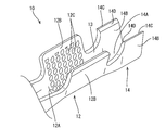
雌端子10は、銅合金からなる基材を打ち抜いて曲げ加工等を施すことにより形成されており、図1に示すように、端子接続部11と、アルミ電線20の芯線21に接続されるワイヤバレル12と、アルミ電線20の絶縁被覆22に圧着されるインシュレーションバレル14と、ワイヤバレル12とインシュレーションバレル14との間を繋ぐ繋ぎ部13と、を有している。端子接続部11は、角筒状をなす箱状に成形されており、その内部に図示しない雄端子のタブが挿入され、電気的に接続されるようになっている。
ワイヤバレル12はオープンバレル形式であって、図2に示すように、左右に伸びる一対のワイヤバレル片12Bが底板部12Aの左右の側縁から互いに対向するようにして立ち上がっている。これらワイヤバレル片12Bは、アルミ電線20の前端部において絶縁被覆22から露出する芯線21に対して内向きに巻き込まれる形で加締められることで、当該芯線21に圧着され、電気的に接続される。なお、ワイヤバレル12のうちアルミ電線20の芯線21に圧着される面(内面)には、芯線21との良好な導通を図るとともに芯線21の保持力を高めるための凹状の複数のセレーション12Cが設けられている。
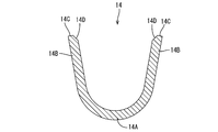
一方、インシュレーションバレル14は同じくオープンバレル形式であって、繋ぎ部13を挟んでワイヤバレル12の後方に設けられており、左右対称な同形同大の略矩形状の一対のインシュレーションバレル片14B(圧着片の一例)が、底板部14Aの左右の側縁から左右対称となる位置において延出されて互いに対向するように立ち上がっている。言い換えると、一対のインシュレーションバレル片14Bは、アルミ電線20の長手方向(前後方向)と交差する左右方向に延出した形態とされている。
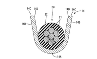
これら一対のインシュレーションバレル片14Bは、底板部14Aに載置されたアルミ電線20の絶縁被覆22の外周に巻き付けられ、絶縁被覆22の外周面に対して径方向に圧着されるようになっている。一対のインシュレーションバレル片14Bは、絶縁被覆22に圧着される際には、平坦面状とされた互いの先端部分14Cが対向するとともに突き合わされる形態とされる。なお、一対のインシュレーションバレル片14Bは、絶縁被覆22に圧着された状態において、絶縁被覆22が所望の圧縮率で圧縮される長さ寸法に、予め設定されている。
さらに、インシュレーションバレル片14Bの先端部分14Cのうち、絶縁被覆22に圧着された状態において絶縁被覆22側に配される内側の縁部の角部は、図2および図3に示すように、アルミ電線20の長手方向(前後方向)に沿って延びるように先端側に向けて斜めに切り欠かれており、この切り欠かれた部分が傾斜部14Dとされている。この傾斜部14Dは、インシュレーションバレル片14Bの先端側に向かって傾斜した形状をなしている。
続いて、雌端子10およびアルミ電線20を組み付ける手順について説明する。まず、ワイヤバレル12およびインシュレーションバレル14の底板部12A、14A、および、繋ぎ部13の上面に、端末において絶縁被覆22が皮剥ぎされて芯線21が露出したアルミ電線20を載置する(図4参照)。ここで、アルミ電線20は、繋ぎ部13上に芯線21と絶縁被覆22との境界部分が配されるように載置され、雌端子10に対するアルミ電線20の前後の位置が決定される(図1参照)。
次に、ワイヤバレル12における一対のワイヤバレル片12Bをアルミ電線20の芯線21に対して内側に巻き込むようにして圧着すると共に、インシュレーションバレル14における一対のインシュレーションバレル片14Bをアルミ電線20の絶縁被覆22に巻き付けるようにして圧着する。
この圧着の過程において、芯線21に対してワイヤバレル12を圧着する際には、セレーション12Cの凹部の孔縁が芯線21に食い込むことで、芯線21に形成された酸化皮膜が破壊されるとともに、ワイヤバレル12が芯線21に対して強固に圧着固定される。
一方、絶縁被覆22に対してインシュレーションバレル14を圧着する際には、一対のインシュレーションバレル片14Bを、それらの先端部分14Cが互いに対向するとともに突き合わされてぴったり重なるように、絶縁被覆22の外周に巻きつけつつ加締める(図5参照)。このように一対のインシュレーションバレル片14Bが絶縁被覆22に圧着された状態において、これらの突き合わせ部分の内周面側には、一対の傾斜部14Dにより、径方向の外側に向けて断面がなだらかな山状に窪んだ凹状部15が形成される。
またこのような圧着状態において、インシュレーションバレル14の内周面(絶縁被覆22側の面)は、ほぼなだらかに連続した状態とされている。詳細には、上述した凹状部15が形成されているものの、この凹状部15(傾斜部14D)は直角状の段差や鋭角なエッジとは異なり、なだらかな状態でインシュレーションバレル片14Bの傾斜部14Dを除く内周面と連続している。
また、一対のインシュレーションバレル片14Bの長さ寸法は、インシュレーションバレル14が絶縁被覆22に圧着された状態において絶縁被覆22が所望の圧縮率となるように予め設定されているから、絶縁被覆22は過不足ない所望の圧縮率で圧縮される。
以上のように、芯線21に対してワイヤバレル12が圧着固定され、絶縁被覆22に対してインシュレーションバレル14が圧着固定されることで、アルミ電線20の端末に雌端子10が取り付けられた端子付き電線30が得られる。
次に、本実施形態の雌端子10および端子付き電線30の作用効果について説明する。本実施形態の端子付き電線30によれば、インシュレーションバレル14が絶縁被覆22に圧着された状態において、一対のインシュレーションバレル片14Bの先端部分14Cは互いにぴったり重なるように突き合わされているから、インシュレーションバレル片14Bのうち絶縁被覆22に接触する内周面側に絶縁被覆22に対して局所的に強く押し当てられる部分がなく、高圧縮な状態としても絶縁被覆22にエッジ等が食い込んで傷がつくことが抑制される。
また、インシュレーションバレル14を強い力で圧着する際には、一対のインシュレーションバレル片14Bを加締める過程において、絶縁被覆22の一部が下方から上方に向けて押し寄せられ、一対の先端部分14C間に噛み込まれそうになる場合があるが、そのような場合でも、噛み込まれそうになった部分は上記凹状部15内に逃がされるため、噛み込を回避することができる。
もって、インシュレーションバレル14を従来と比較して絶縁被覆22に対して高圧縮で圧着することができ、インシュレーションバレル14の保持力が高い雌端子10および端子付き電線30を得ることができる。
<他の実施形態>
本明細書で開示される技術は上記記述及び図面によって説明した実施形態に限定されるものではなく、例えば次のような種々の態様も含まれる。
本明細書で開示される技術は上記記述及び図面によって説明した実施形態に限定されるものではなく、例えば次のような種々の態様も含まれる。
(1)上記実施形態では、インシュレーションバレル14の先端部分14Cの内周側の縁部に傾斜部14Dを設けたが、傾斜部14Dは必ずしも設けなくてもよい。
(2)上記実施形態では、インシュレーションバレル片14Bの先端部分14Cを平坦面状としたが、セレーション等の若干の凹凸を設ける等、平坦面状に限らず他の形態としてもよい。
(3)端子の種類や形態は、上記実施形態に限られるものではない。例えば、図6に示すように、上記実施形態と同様の形態のインシュレーションバレル44の後方側に、ゴム栓を保持するための一対のゴム栓用バレル46を一体に設けた端子40に適用することもできる。また、雌端子10に限らず、絶縁被覆22に圧着するインシュレーションバレルが設けられた雄端子など、インシュレーションバレルが設けられた端子全般に本明細書で開示した技術を広く適用できる。
10:雌端子(端子)
12:ワイヤバレル
13:繋ぎ部
14:インシュレーションバレル
14B:インシュレーションバレル片(圧着片)
14C:先端部分
14D:傾斜部
15:凹状部
20:アルミ電線
21:芯線
22:絶縁被覆
30:端子付き電線
12:ワイヤバレル
13:繋ぎ部
14:インシュレーションバレル
14B:インシュレーションバレル片(圧着片)
14C:先端部分
14D:傾斜部
15:凹状部
20:アルミ電線
21:芯線
22:絶縁被覆
30:端子付き電線
Claims (3)
- 芯線を絶縁被覆で覆ったアルミ電線の端末に接続される端子であって、
前記アルミ電線の長手方向と交差する方向に延出して形成され、前記絶縁被覆の外周面に圧着される一対の圧着片を備えており、
前記一対の圧着片は前記絶縁被覆に圧着された状態において互いの先端部分が対向するとともに突き当てられる端子。 - 前記先端部分で前記絶縁被覆側に配される内側縁部は、前記圧着片の先端に向かって斜めに切り欠かれた傾斜部とされている請求項1に記載の端子。
- 芯線を絶縁被覆で覆ったアルミ電線と、前記アルミ電線に接続される請求項1または請求項2に記載の端子とを備えた端子付き電線。
Priority Applications (3)
| Application Number | Priority Date | Filing Date | Title |
|---|---|---|---|
| DE112016001748.0T DE112016001748B4 (de) | 2015-04-16 | 2016-03-30 | Mit Anschluss versehener elektrischer Draht |
| CN201680021549.6A CN107431283B (zh) | 2015-04-16 | 2016-03-30 | 端子以及带端子的电线 |
| US15/564,270 US9972920B1 (en) | 2015-04-16 | 2016-03-30 | Terminal and terminal-equipped electric wire |
Applications Claiming Priority (2)
| Application Number | Priority Date | Filing Date | Title |
|---|---|---|---|
| JP2015084268A JP6376030B2 (ja) | 2015-04-16 | 2015-04-16 | 端子および端子付き電線 |
| JP2015-084268 | 2015-04-16 |
Publications (1)
| Publication Number | Publication Date |
|---|---|
| WO2016167125A1 true WO2016167125A1 (ja) | 2016-10-20 |
Family
ID=57127225
Family Applications (1)
| Application Number | Title | Priority Date | Filing Date |
|---|---|---|---|
| PCT/JP2016/060343 Ceased WO2016167125A1 (ja) | 2015-04-16 | 2016-03-30 | 端子および端子付き電線 |
Country Status (5)
| Country | Link |
|---|---|
| US (1) | US9972920B1 (ja) |
| JP (1) | JP6376030B2 (ja) |
| CN (1) | CN107431283B (ja) |
| DE (1) | DE112016001748B4 (ja) |
| WO (1) | WO2016167125A1 (ja) |
Cited By (1)
| Publication number | Priority date | Publication date | Assignee | Title |
|---|---|---|---|---|
| US20220158364A1 (en) * | 2020-11-19 | 2022-05-19 | Yazaki Corporation | Electric wire with terminal and terminal crimping device |
Families Citing this family (4)
| Publication number | Priority date | Publication date | Assignee | Title |
|---|---|---|---|---|
| JP6225313B2 (ja) * | 2016-03-04 | 2017-11-08 | 株式会社デルタプラス | 圧着接続端子及びその製造方法 |
| JP7132601B2 (ja) * | 2018-07-30 | 2022-09-07 | 日本圧着端子製造株式会社 | 電線と保持金具との接続構造 |
| JP6947139B2 (ja) * | 2018-08-29 | 2021-10-13 | 株式会社オートネットワーク技術研究所 | 過電流遮断ユニット |
| JP2023163349A (ja) * | 2022-04-28 | 2023-11-10 | 矢崎総業株式会社 | 端子付き電線 |
Citations (2)
| Publication number | Priority date | Publication date | Assignee | Title |
|---|---|---|---|---|
| JPH0572053U (ja) * | 1992-01-08 | 1993-09-28 | 日本エー・エム・ピー株式会社 | ワイヤ圧着端子 |
| JP2013171753A (ja) * | 2012-02-22 | 2013-09-02 | Auto Network Gijutsu Kenkyusho:Kk | 端子付電線及びその製造方法 |
Family Cites Families (18)
| Publication number | Priority date | Publication date | Assignee | Title |
|---|---|---|---|---|
| DE19526738C2 (de) * | 1995-07-21 | 2003-07-24 | Whitaker Corp | Buchsenkontakt mit Überfeder |
| JP2005050736A (ja) * | 2003-07-30 | 2005-02-24 | Furukawa Electric Co Ltd:The | アルミ電線への端子圧着構造及び端子付アルミ電線の製造方法 |
| JP4066978B2 (ja) * | 2004-05-24 | 2008-03-26 | 住友電装株式会社 | ファストン端子 |
| US7175487B2 (en) * | 2004-06-28 | 2007-02-13 | Delphi Technologies, Inc. | Electrical terminal element |
| US7722416B2 (en) * | 2008-10-02 | 2010-05-25 | Delphi Technologies, Inc. | Electrical connection system for use on aluminum wires |
| CN102742083B (zh) * | 2010-02-05 | 2015-05-20 | 古河电气工业株式会社 | 压接端子、连接构造体以及压接端子的制作方法 |
| CN102782940B (zh) * | 2010-02-05 | 2015-11-25 | 古河电气工业株式会社 | 连接构造体 |
| JP5375687B2 (ja) | 2010-03-15 | 2013-12-25 | 株式会社オートネットワーク技術研究所 | 端子金具、及び端子金具付き電線 |
| CN101938044A (zh) * | 2010-08-09 | 2011-01-05 | 贾岳水 | 带预留导向部位的电瓶线接头 |
| JP5434847B2 (ja) * | 2010-08-17 | 2014-03-05 | 住友電装株式会社 | 端子金具 |
| JP5636929B2 (ja) * | 2010-12-10 | 2014-12-10 | 住友電装株式会社 | 端子金具 |
| US8485853B2 (en) * | 2011-11-03 | 2013-07-16 | Delphi Technologies, Inc. | Electrical contact having knurl pattern with recessed rhombic elements that each have an axial minor distance |
| JP5741409B2 (ja) * | 2011-11-29 | 2015-07-01 | 株式会社オートネットワーク技術研究所 | 端子金具、及び端子付き電線 |
| JP5682547B2 (ja) * | 2011-12-12 | 2015-03-11 | 株式会社オートネットワーク技術研究所 | 端子金具 |
| DE112013001440T5 (de) * | 2012-03-15 | 2015-01-22 | Autonetworks Technologies, Ltd. | Anschluss und mit einem Anschluss versehener Draht |
| JP5704422B2 (ja) * | 2012-03-28 | 2015-04-22 | 株式会社オートネットワーク技術研究所 | 端子付き電線 |
| JP6056584B2 (ja) * | 2013-03-22 | 2017-01-11 | 株式会社オートネットワーク技術研究所 | 端子付き被覆電線、ワイヤーハーネス、及び防食剤 |
| US20160359244A1 (en) * | 2013-09-12 | 2016-12-08 | Furukawa Electric Co., Ltd. | Terminal, connection structural body, and method of manufacturing terminal |
-
2015
- 2015-04-16 JP JP2015084268A patent/JP6376030B2/ja active Active
-
2016
- 2016-03-30 WO PCT/JP2016/060343 patent/WO2016167125A1/ja not_active Ceased
- 2016-03-30 US US15/564,270 patent/US9972920B1/en active Active
- 2016-03-30 CN CN201680021549.6A patent/CN107431283B/zh active Active
- 2016-03-30 DE DE112016001748.0T patent/DE112016001748B4/de active Active
Patent Citations (2)
| Publication number | Priority date | Publication date | Assignee | Title |
|---|---|---|---|---|
| JPH0572053U (ja) * | 1992-01-08 | 1993-09-28 | 日本エー・エム・ピー株式会社 | ワイヤ圧着端子 |
| JP2013171753A (ja) * | 2012-02-22 | 2013-09-02 | Auto Network Gijutsu Kenkyusho:Kk | 端子付電線及びその製造方法 |
Cited By (2)
| Publication number | Priority date | Publication date | Assignee | Title |
|---|---|---|---|---|
| US20220158364A1 (en) * | 2020-11-19 | 2022-05-19 | Yazaki Corporation | Electric wire with terminal and terminal crimping device |
| US11677167B2 (en) * | 2020-11-19 | 2023-06-13 | Yazaki Corporation | Electric wire with terminal and terminal crimping device |
Also Published As
| Publication number | Publication date |
|---|---|
| DE112016001748T5 (de) | 2017-12-28 |
| DE112016001748B4 (de) | 2023-06-22 |
| US20180138600A1 (en) | 2018-05-17 |
| JP2016207305A (ja) | 2016-12-08 |
| JP6376030B2 (ja) | 2018-08-22 |
| US9972920B1 (en) | 2018-05-15 |
| DE112016001748T8 (de) | 2018-05-03 |
| CN107431283A (zh) | 2017-12-01 |
| CN107431283B (zh) | 2020-02-07 |
Similar Documents
| Publication | Publication Date | Title |
|---|---|---|
| JP2010146739A (ja) | 電線接続スリーブ、電線接続スリーブの製造方法、電線接続スリーブが予め圧着されたリペア電線、および電線の接続方法 | |
| JP6376030B2 (ja) | 端子および端子付き電線 | |
| WO2010024033A1 (ja) | 端子金具及び端子金具の製造方法 | |
| JP5074984B2 (ja) | 圧着端子 | |
| JP2009231080A (ja) | アルミ電線用圧着端子 | |
| JP6421737B2 (ja) | 端子付き電線の製造方法、圧着冶具、および端子付き電線 | |
| JP2010176886A (ja) | 電線接続スリーブ、リペア電線、電線接続スリーブの製造方法、および電線の接続方法 | |
| JP2019175727A (ja) | 端子付き電線 | |
| WO2017212920A1 (ja) | 端子付き電線 | |
| JP6319635B2 (ja) | 端子および端子付き電線 | |
| WO2016143466A1 (ja) | 端子付き電線及び端子 | |
| WO2015068650A1 (ja) | 圧着端子 | |
| JP6479535B2 (ja) | 端子、端子付き電線、ワイヤハーネス構造体 | |
| US10340610B2 (en) | Structure for improving impact strength of a terminal | |
| JP5838939B2 (ja) | 端子付き電線 | |
| CN110707443B (zh) | 带端子的电线 | |
| WO2018092597A1 (ja) | 圧着端子および端子付き電線 | |
| WO2016186021A1 (ja) | 端子、及び端子付き電線 | |
| JP2010073345A (ja) | 端子金具の接続構造、端子金具付き電線、および端子金具付き電線の製造方法 | |
| WO2015053208A1 (ja) | 圧着端子 | |
| JP2015099639A (ja) | 端子金具 | |
| WO2016167120A1 (ja) | 端子および端子付き電線 | |
| WO2015053315A1 (ja) | 圧着端子 | |
| JP6935310B2 (ja) | 端子付き電線の製造方法 | |
| JP5842802B2 (ja) | 端子付き電線 |
Legal Events
| Date | Code | Title | Description |
|---|---|---|---|
| 121 | Ep: the epo has been informed by wipo that ep was designated in this application |
Ref document number: 16779916 Country of ref document: EP Kind code of ref document: A1 |
|
| WWE | Wipo information: entry into national phase |
Ref document number: 15564270 Country of ref document: US |
|
| WWE | Wipo information: entry into national phase |
Ref document number: 112016001748 Country of ref document: DE |
|
| 122 | Ep: pct application non-entry in european phase |
Ref document number: 16779916 Country of ref document: EP Kind code of ref document: A1 |