WO2016167027A1 - テンションロッドの格納構造 - Google Patents
テンションロッドの格納構造 Download PDFInfo
- Publication number
- WO2016167027A1 WO2016167027A1 PCT/JP2016/055372 JP2016055372W WO2016167027A1 WO 2016167027 A1 WO2016167027 A1 WO 2016167027A1 JP 2016055372 W JP2016055372 W JP 2016055372W WO 2016167027 A1 WO2016167027 A1 WO 2016167027A1
- Authority
- WO
- WIPO (PCT)
- Prior art keywords
- jib
- rod
- tension rod
- connecting portion
- posture
- Prior art date
- Legal status (The legal status is an assumption and is not a legal conclusion. Google has not performed a legal analysis and makes no representation as to the accuracy of the status listed.)
- Ceased
Links
Images





Classifications
-
- B—PERFORMING OPERATIONS; TRANSPORTING
- B66—HOISTING; LIFTING; HAULING
- B66C—CRANES; LOAD-ENGAGING ELEMENTS OR DEVICES FOR CRANES, CAPSTANS, WINCHES, OR TACKLES
- B66C23/00—Cranes comprising essentially a beam, boom, or triangular structure acting as a cantilever and mounted for translatory of swinging movements in vertical or horizontal planes or a combination of such movements, e.g. jib-cranes, derricks, tower cranes
- B66C23/62—Constructional features or details
- B66C23/64—Jibs
- B66C23/70—Jibs constructed of sections adapted to be assembled to form jibs or various lengths
Definitions
- the present invention relates to a retracting structure for a tension rod that is stretched between the upper end of the boom and the appropriate position of the tip of the jib.
- a boom head is provided at the tip of the tip of the boom (main jib), and a jib (auxiliary jib) is often attached to the boom head.
- the jib is configured such that the base end portion engages with the lower end of the front end boom.
- Typical examples of the jib storage method include a lower-holding storage method in which the jib is disposed on the lower surface of the boom in the stored state, and a lateral-holding storage method in which the jib is disposed on the side surface of the boom.
- Patent Document 1 the one disclosed in Patent Document 1 is known as a mobile crane of a hugging and storing method.
- the mobile crane of Patent Document 1 on the lower surface of the boom, the jib base end is directed to the boom tip, and the jib tip is directed to the boom base.
- a bracket-like rod support device is installed on the lower surface of the jib to hold the intermediate portion of the tension rod (see FIG. 7 of Patent Document 1). More specifically, the rod support device has a fixed bracket provided integrally with the lower surface of the jib, and a movable bracket that is rotatably attached to the fixed bracket.
- the rod support device described in Patent Document 1 described above has a complicated structure, and when the jib is extended from the jib retracted posture, the rod support device that holds the intermediate portion of the tension rod is manually operated. A step to remove was necessary. Furthermore, since the configuration only supports the weight of the vehicle, there is a problem that it generates a contact sound by vibrating during traveling.
- an object of the present invention is to provide a tension rod storage structure that has a simple configuration and does not require an operation at an intermediate portion of the tension rod when the jib is extended.
- a tension rod storage structure is a tension rod storage structure that is stretched between an upper end of a boom tip and a proper position of the jib tip in a jib working posture,
- a tension rod having a rod distal end coupling portion coupled to the distal end appropriate position and a rod proximal end coupling portion coupled to the proximal end appropriate position of the jib in the jib retracted position; a jib distal end coupled to the rod distal end coupling portion
- a jib having a connecting portion, a U-shaped guide member that receives an intermediate portion of the tension rod in a jib retracted posture, and a jib base end connecting portion that is connected to the rod base end connecting portion.
- the rod tip connecting portion is connected to the jib tip connecting portion, and the rod base end connecting portion is connected to the jib base end connecting portion.
- the tension rod storage structure of the present invention comprises a tension rod having a rod tip connecting portion and a rod base end connecting portion, a jib tip connecting portion, a U-shaped guide member, and a jib base end connecting portion.
- the rod tip connecting portion is connected to the jib tip connecting portion
- the rod base end connecting portion is connected to the jib base end connecting portion.
- the intermediate portion of the tension rod is pressed against the U-shaped guide member by the restoring force. For this reason, it is a simple structure, and it becomes a tension rod storage structure that does not require an operation at the intermediate portion of the tension rod when the jib is extended. Furthermore, it is possible to suppress the generation of contact sound due to vibration during traveling.
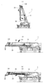
- FIG. It is a side view of a rough terrain crane. It is a side view of the jib storing posture of the jib of Example 1. It is a top view of the jib storage attitude
- FIG. It is sectional drawing of a guide member. It is a side view of a guide member. It is explanatory drawing of the procedure of jib storage.
- (A) is a tension rod removing step, and (b) is a boom raising / retracting step. It is explanatory drawing of the procedure of jib storage.
- (C) is an auxiliary rope installation step, (d) is a boom defeat / jib removal step, and (e) is a jib side up step.
- FIG. 1 It is sectional drawing of a horizontal holding posture. It is sectional drawing of a holding posture. It is a side view of the jib storage attitude
- the rough terrain crane 1 includes a vehicle body 10 that is a main body portion of a vehicle having a traveling function, outriggers 11,...
- a swivel base 12 attached to the swivel base 12 and a boom 14 attached to a bracket 13 erected on the swivel base 12 are provided.
- the boom 14 is configured in a telescopic manner by a distal end boom 143, a proximal end boom 141, and an intermediate boom 142 between them.
- a hoisting cylinder 15 is bridged between the lower portion of the base end boom 141 and the bracket 13 so that the entire boom 14 can be hoisted.
- the jib 30 and the tension rod 20 are stored in a sideways posture on the side surface of the proximal end boom 141.
- the tension rod 20 is formed in a long rod shape as a whole.
- the tension rod 20 is connected to a length adjusting portion 24 having a plurality of mounting holes, a main body portion 25 made of a hollow steel pipe pipe, and a jib tip connecting portion 31 of the jib 30 disposed on the front end side of the main body portion 25.
- a grip 23 for gripping the vicinity.
- the rod tip connecting portion 21 is rotatably attached by communicating a pin with the jib tip connecting portion 31.
- the rod tip connecting portion is slidably supported in a long hole as a jib tip connecting portion, and can be configured to slide by extending and retracting a tilt cylinder (see Example 2). ).
- the jib 30 is formed in a substantially Y shape as a whole.
- the base end side of the jib 30 (during the jib operation) is bifurcated so as to engage with engaging portions (not shown) on both sides of the lower end of the boom head 144 (see FIG. 1) at the tip of the tip boom 143.
- a U-shaped engaging portion 33 is attached to the branched tip.
- the tip side of the jib 30 has a box-like structure, and two plates are attached to the tip of the jib 30 so that the sheave is rotatably held.
- the jib 30 of this embodiment includes a jib tip connecting portion 31 connected to the rod tip connecting portion 21, a U-shaped guide member 40 that receives an intermediate portion of the tension rod 20 in the jib retracted posture, and a rod proximal end.
- the jib tip connecting portion 31 is disposed at the upper end of the jib 30 and is connected to the rod tip connecting portion 21 of the tension rod 20 by a pin.
- tip connection part slidably in the axial direction of a jib can also be formed so that it may mention later (refer Example 2).
- the jib base end connecting portion 32 is disposed on the base end upper portion of the jib 30 and is connected to the rod base end connecting portion 22 of the tension rod 20 by a pin.
- the operator in order to connect the rod base end connecting portion 22 to the jib base end connecting portion 32, the operator holds the grip 23 of the tension rod 20 by hand and pushes it down.
- the tension rod 20 is bent downward by its own weight while the intermediate portion is supported by the guide member 40, the force to push down is sufficiently large by human power.
- the guide member 40 is formed in the shape of an arm that protrudes upward and outward from the jib 30 as a whole.
- the guide member 40 includes a U-shaped portion 41 that receives the tension rod 20, an arm portion 42 that supports the U-shaped portion 41, and a reinforcing portion 43 that supports the U-shaped portion 41 and the arm portion 42 from below. .
- the U-shaped portion 41 is formed so as to open upward in the jib work posture, in other words, to open in the opposite direction of the jib 30.
- the position of the U-shaped portion 41 in the width direction of the jib 30 is set so that the center of the U-shaped portion 41 in the width direction is positioned on a straight line connecting the jib distal end connecting portion 31 and the jib base end connecting portion 32.
- the height of the U-shaped portion 41 of the guide member 40 from the upper surface of the jib 30 is a predetermined distance above the straight line connecting the jib distal end connecting portion 31 and the jib proximal end connecting portion 32 (jib working posture). It is considered as a remote position. That is, the height of the U-shaped portion 41 is such that, even when the tension rod 20 is bent by its own weight in the inverted posture where the tension rod 20 is positioned below the jib 30, the tension rod 20 is placed on the bottom surface portion of the U-shaped portion 41. It is set to be pressed and fixed.
- the deflection amount (shape) due to the weight of the entire length of the tension rod 20 at the position of the guide member 40 in the inverted posture is calculated in advance, and at least above the calculated deflection amount (lower in the use posture and the inverted posture).
- the U-shaped portion 41 may be arranged. Therefore, when the tension rod base end connecting portion 22 is connected to the jib base end connecting portion 32 during the storage operation, the guide member 40 is bent in a state where the intermediate portion is supported. It is necessary to manually apply a force corresponding to the difference in deflection amount.
- the height of the guide member 40 adds a predetermined margin height to the height calculated based on the above-described deflection amount in consideration of vibrations or the like when traveling in a model in which the retracted posture is a holding posture. It is preferable. However, the height of the guide member 40 needs to be within a range where the pipe-shaped main body 25 of the tension rod 20 is elastically deformed and can be connected by being pushed by hand.
- the boom 14 is tilted to a substantially horizontal state, and the tension rod 20 is removed from the boom head 144. That is, the rod proximal end connecting portion 22 is removed from the boom head 144 by removing the pin while the rod distal end connecting portion 21 is connected to the jib distal end connecting portion 31 by the pin.
- the grip 23 of the tension rod 20 is grasped and pushed downward by hand to align the position, and the rod proximal end connecting portion 22 Are connected to the jib base end connecting portion 32 by a pin.
- the boom 14 is raised while the boom 14 is contracted.
- the jib 30 is rotated by its own weight and becomes substantially vertical.
- the auxiliary wire 50 is hung on the jib 30 (and the tension rods 20, 20) and wound up with a winch to draw the jib 30 to the lower surface of the boom 14.
- the boom 14 is again lowered to a substantially horizontal state, and the jib 30 is removed from the boom head 144. That is, in a state where the boom 14 is tilted, the pin is pulled out from the engaging portion 33 of the jib 30 and the boom 14 is temporarily extended, so that the jib 30 and the boom head 144 are disengaged. Further, a side up cylinder (not shown) arranged on the side surface of the proximal boom 141 is connected to the jib 30 by a pin.
- the jib 30 is pulled up from the lower surface of the proximal boom 141 to the side surface of the proximal boom 141 by contracting the side-up cylinder. And the proper position of the jib 30 is fixed to the proximal end boom 141, and the storage of the jib 30 is completed.
- the jib 30 is swung out in front of the boom head 144 in the process of FIG.
- the tension rod 20 is located above the jib 30.
- the intermediate portion of the tension rod 20 is placed in the guide member 40, and the base end connecting portion 22 of the tension rod 20 is moved to the base of the jib 30 while being held down and elastically deformed. It is connected to the end connecting part 32 by a pin.
- the jib 30 is hung from below the boom head 144. In this state, gravity acts in the length direction of the tension rod 20, so that the tension rod 20 does not deviate from the guide member 40.
- the jib 30 is attracted to the lower surface of the boom 14, and the tension rod 20 is down and the jib 30 is up.
- gravity acts in a direction in which the tension rod 20 deviates from the guide member 40. Therefore, this state is a state in which the tension rod 20 is most likely to deviate.
- the intermediate portion of the tension rod 20 is moved by the restoring force of the tension rod 20. It is pressed against the bottom.
- the load relationship between the tension rod 20 and the jib 30 is the same as that shown in FIG. 9 although there are differences in the process.
- the jib 30 is drawn to the side surface of the boom 14, and the tension rod 20 is outside and the jib 30 is inside.
- This state is the retracted posture of the jib 30 and the tension rod 20 in the horizontal holding posture.
- the restoring force of the tension rod 20 acts in the direction of pushing the bottom wall of the U-shaped portion 41 horizontally inward, and the weight of the tension rod 20 is the side wall of the U-shaped portion 41. Acts in the direction of pushing down vertically. That is, the action direction of the restoring force and the action direction of the dead weight are substantially orthogonal.
- the weight is received by the side wall of the U-shaped portion 41, and the restoring force is received by the bottom wall of the U-shaped portion 41. That is, no force acts in the direction in which the tension rod 20 deviates from the U-shaped portion 41. Rather, the force acts in a direction that prevents the tension rod 20 from deviating from the U-shaped portion 41.
- the tension rod storage structure S of the present embodiment is the tension rod storage structure S stretched between the upper end of the boom 14 and the appropriate tip of the jib 30 in the jib working posture. is there.
- the tension rod storage structure S includes a rod front end connecting portion 21 connected to a proper end of the jib 30 and a rod proximal end connecting portion 22 connected to a proper end of the jib 30 in the jib retracted posture.
- a jib 30 having a jib proximal end coupling portion 32.
- the rod tip connecting portion 21 is connected to the jib tip connecting portion 31 and the rod base end connecting portion 22 is connected to the jib base end connecting portion 32, so that the tension rod 20 is elastically deformed.
- the intermediate portion of the tension rod 20 is pressed against the U-shaped guide member 40 by the restoring force due to. Therefore, the tension rod storage structure S has a simple configuration and does not require an operation at the intermediate portion of the tension rod 20 when the jib 30 is extended.
- the tension rod 20 can be stored and held by the guide member 40 having a simple structure. Furthermore, since the guide member 40 has a structure in which the upper side is open, it is not necessary to release the catch member as in the prior art when the jib 30 is extended.
- the tension rod 20 has a bottom surface portion of the U-shaped guide member 40 so that the tension rod 20 does not deviate from the guide member 40 by its own weight.
- the height of the guide member 40 from the jib 30 is set so as to be pressed and fixed. That is, in the storing operation, the posture of the jib 30 changes depending on each process. In each step, the load state in the reverse posture in which the tension rod 20 is positioned below the jib 30 is the load state in which the tension rod 20 is most likely to deviate from the guide member 40.
- the tension rod 20 is It is possible to prevent the guide member 40 from coming off.
- the bottom surface portion of the guide member 40 may be disposed at a higher position in the working posture than the amount of bending due to its own weight in the reversed posture.
- the jib 30 can be configured to be held in a horizontal holding posture in which the lower surface of the jib 30 in the jib working posture is pulled toward the side face of the proximal boom 141.
- the weight of the tension rod 20 is supported by the side wall of the guide member 40, and at the same time, the restoring force due to the elastic deformation of the tension rod 20 acts in the direction of pushing the bottom of the guide member 40. That is, in the horizontal holding posture, the restoring force due to the elastic deformation of the tension rod 20 acts in a direction that prevents the deviation from the guide member 40, so that the tension rod 20 does not deviate from the guide member 40.
- the generation of contact noise due to running vibration can be suppressed by bending the tension rod 20 to suppress rattling.
- the jib 30 can be configured to be held in a holding posture in which the lower surface of the jib 30 in the jib working posture is pulled toward the lower surface of the proximal boom 141.
- the weight of the tension rod 20 acts in a direction opposite to the restoring force due to the elastic deformation of the tension rod 20.
- the intermediate portion of the tension rod 20 is pressed against the U-shaped guide member 40, deviation from the guide member 40 of the tension rod 20 can be prevented even in the holding position.
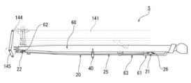
- the tension rod storage structure S of the present embodiment is configured by the tension rod 20 and the jib 60, as in the first embodiment.
- the tension rod 20 is connected to the tension rod connecting link 145 in the working posture at the base end portion, and the tilt cylinder is slidably supported on the support member 61 in the working posture and the retracted posture. 63.
- the tension rod 20 is connected to the main body portion 25, the rod tip connecting portion 21 slidably supported by the support member 61 as the jib tip connecting portion 31, and the jib proximal end connecting portion 62 in the jib retracted position. And a rod base end coupling portion 22 coupled to the tension rod connection link 145 in the working posture.
- the two rod tip connecting portions 21 and 21 of the present embodiment are connected to each other via a sliding shaft 26 that is inserted into the support member 61 and supported slidably.
- the jib 60 includes a support member 61 as a jib tip connecting portion that slidably supports the slide shaft 26 that connects the rod tip connecting portions 21 in the axial direction of the jib 60, and the tension rod 20 in the jib retracted position.
- the U-shaped guide member 40 that receives the intermediate portion, the jib proximal end coupling portion 62 that is coupled to the rod proximal end coupling portion 22 in the jib retracted posture, and the rod distal end coupling portion 21 that extends and contracts in the axial direction of the jib 60.
- a tilt cylinder 63 that slides the sliding shaft 26 to be connected.
- the support member 61 has a long hole on the side surface, and the sliding shaft 26 is slidably supported in the long hole.
- the slide shaft 26 that connects the rod tip connecting portions 21 is disposed at a position near the base end in the support member 61, and the rod base end connecting portion 22 is the jib base end.
- the intermediate portion of the tension rod 20 is pressed against the U-shaped guide member 40 by being connected to the connecting portion 62.
- the slide shaft 26 that connects the rod tip connecting portions 21 is moved to a position closer to the tip by the tilt cylinder 63 in the support member 61, and the rod base end connecting portion. 22 is connected to the tension rod connection link 145, and the intermediate portion of the tension rod 20 moves away from the guide member 40 and moves upward.
- the jib retracted posture is the holding posture
- gravity acts in the direction in which the tension rod 20 deviates from the guide member 40 as shown in FIG.
- the intermediate portion of the tension rod 20 is the bottom surface portion of the guide member 40 due to the restoring force of the tension rod 20. It is pressed against.
- the jib retracted posture is a horizontal holding posture
- the restoring force of the tension rod 20 acts in the direction of pushing the bottom wall of the U-shaped portion 41 horizontally inward as shown in FIG.
- the own weight acts in the direction of pushing the side wall of the U-shaped portion 41 vertically downward. In this state, the restoring force of the tension rod 20 acts in a direction that prevents the tension rod 20 from deviating from the U-shaped portion 41.
- the tension rod storage structure S of this embodiment includes the tension rod 20 and the jib 60 as in the first embodiment. While being connected to the support member 61 as the distal end connecting portion and the rod proximal end connecting portion 22 being connected to the jib proximal end connecting portion 62, the intermediate force of the tension rod 20 is restored by the restoring force due to the elastic deformation of the tension rod 20. The portion is pressed against the U-shaped guide member 40. Therefore, the tension rod storage structure S has a simple configuration and does not require an operation at the intermediate portion of the tension rod 20 when the jib 60 is extended.
- the tension rod connection link 145 that is connected to the rod proximal end connecting portion 22 in the working posture is attached to the boom head 145 at the distal end of the boom 14.
- the jib 60 slides the rod tip connecting portion 21 by extending and contracting in the axial direction of the jib 60 and a support member 61 as a jib tip connecting portion that supports the rod tip connecting portion 21 slidably in the axial direction of the jib 60.
- a tilt cylinder 63 to be moved.
- the rod distal end connecting portion 21 is disposed at a position near the proximal end in the support member 61, and the rod proximal end connecting portion 22 is connected to the jib proximal end connecting portion 62 in the tensioned state.
- the intermediate portion of the tension rod 20 is pressed against the U-shaped guide member 40 by the restoring force due to the elastic deformation of the rod 20.
- the rod distal end connecting portion 21 is slidably moved in the support member 61 by extending and retracting the tilt cylinder 63 and is disposed at a predetermined position, and the rod proximal end connecting portion 22 is a tension rod connecting link. 145 is connected.
- the tension rod storage structure S of the present embodiment can be applied to the tension rod 20 and the jib 60 having a different form from that of the first embodiment.
- the tension rod 20 can be stored and held by the guide member 40 having a simple structure by utilizing the bending of the tension rod 20.
- the guide member 40 since the guide member 40 has a structure in which the upper side is opened, it is not necessary to release the catch member as in the prior art when the jib 60 is extended. Furthermore, there is an effect of preventing damage to the tension rod 20 due to forgetting to release the catch member when the jib is extended.
- the “U-shaped” guide member 40 is a U-shaped in which the bottom wall and the side wall are substantially orthogonal to each other has been described.
- a U-shape may be used, and a U-shape with a curved bottom wall is also included.
- the “U-shape” in the present invention is intended to be an open shape in which the upper side is open in the jib work posture, and in a strict sense, it is a “U” shape. Is not intended.
- the present invention is not limited to this.
- the guide member 40 can also be arrange
Landscapes
- Engineering & Computer Science (AREA)
- Mechanical Engineering (AREA)
- Jib Cranes (AREA)
Abstract
ジブを張り出す際にテンションロッドの中間部での作業を必要としないテンションロッドの格納構造を提供する。ブームの先端上部とジブの先端適所の間に張設されるテンションロッドの格納構造である。テンションロッドの格納構造(S)は、ジブ(30)の先端適所に連結されるロッド先端連結部(21)と、ジブ格納姿勢においてジブ(30)の基端適所に連結されるロッド基端連結部(22)と、を有するテンションロッド(20)と;ロッド先端連結部(21)と連結されるジブ先端連結部(31)と、ジブ格納姿勢においてテンションロッド(20)の中間部を受けるコ字型のガイド部材(40)と、ロッド基端連結部(22)と連結されるジブ基端連結部(32)と、を有するジブ(30)と;を備えている。そして、ジブ格納姿勢において、ロッド先端連結部(21)がジブ先端連結部(31)と連結されるとともに、ロッド基端連結部(22)がジブ基端連結部(32)と連結された状態で、テンションロッド(20)の弾性変形による復元力によって、テンションロッドの中間部がコ字型のガイド部材(40)のコ字部(41)に押し付けられるようになっている。
Description
本発明は、ブームの先端上部とジブの先端適所の間に張設されるテンションロッドの格納構造に関するものである。
従来から、移動式クレーンは、入れ子式に構成されたブームを備えている。このブーム(主ジブ)の先端ブームの先端にはブームヘッドが設けられ、ブームヘッドにジブ(補助ジブ)が装着されることも多い。一般に、ジブは基端部が先端ブームの先端下部と係合するようにされている。
ところで、ジブを使用しない作業の場合には、ジブを格納することが必要となる。ジブの格納方式としては、格納状態においてジブをブームの下面に配置する下抱き格納方式と、ジブをブームの側面に配置する横抱き格納方式とが、代表的である。
このうち下抱き格納方式の移動式クレーンとして、例えば、特許文献1に開示されたものが知られている。特許文献1の移動式クレーンでは、その図1に示すように、ブーム下面において、ジブ基端部をブーム先端に向け、ジブ先端部をブーム基端に向けた状態で格納されるようになっている。その際、ジブの下面にブラケット状のロッド支持装置を設置してテンションロッドの中間部を保持するようになっている(特許文献1の図7参照)。より具体的にいうと、ロッド支持装置は、ジブの下面と一体に設けられた固定ブラケットと、固定ブラケットに回動可能に取り付けられる可動ブラケットとを有している。
しかしながら、上述した特許文献1に記載されたロッド支持装置は、構成が複雑なうえ、ジブ格納姿勢からジブを張り出す際に、テンションロッドの中間部を保持しているロッド支持装置を手作業で外すステップが必要となっていた。さらに、自重を支持するだけの構成のため、走行時に振動して接触音を発生するという問題もあった。
そこで、本発明は、簡単な構成であり、ジブを張り出す際にテンションロッドの中間部での作業を必要としない、テンションロッドの格納構造を提供することを目的としている。
前記目的を達成するために、本発明のテンションロッドの格納構造は、ジブ作業姿勢においてブームの先端上部とジブの先端適所の間に張設されるテンションロッドの格納構造であって、前記ジブの先端適所に連結されるロッド先端連結部と、ジブ格納姿勢において前記ジブの基端適所に連結されるロッド基端連結部と、を有するテンションロッドと;前記ロッド先端連結部と連結されるジブ先端連結部と、ジブ格納姿勢において前記テンションロッドの中間部を受けるコ字型のガイド部材と、前記ロッド基端連結部と連結されるジブ基端連結部と、を有するジブと;を備え、ジブ格納姿勢において、前記ロッド先端連結部が前記ジブ先端連結部と連結されるとともに、前記ロッド基端連結部が前記ジブ基端連結部と連結された状態で、前記テンションロッドの弾性変形による復元力によって、前記テンションロッドの中間部が前記コ字型のガイド部材に押し付けられるようになっている。
このように、本発明のテンションロッドの格納構造は、ロッド先端連結部とロッド基端連結部とを有するテンションロッドと、ジブ先端連結部とコ字型のガイド部材とジブ基端連結部とを有するジブとを備え、ジブ格納姿勢において、ロッド先端連結部がジブ先端連結部と連結されるとともに、ロッド基端連結部がジブ基端連結部と連結された状態で、テンションロッドの弾性変形による復元力によって、テンションロッドの中間部がコ字型のガイド部材に押し付けられるようになっている。このため、簡単な構成であり、ジブを張り出す際にテンションロッドの中間部での作業が必要とされないテンションロッドの格納構造となる。さらに、走行時の振動で接触音を発生することを抑制できる。
以下、本発明の実施の形態について図面を参照して説明する。ただし、以下の実施例に記載されている構成要素は例示であり、本発明の技術範囲をそれらのみに限定する趣旨のものではない。以下の実施例では、ラフテレーンクレーン1を例にして説明するが、これに限定されるものではなく、オールテレーンクレーンなどの移動式クレーンに広く本発明を適用できる。
(構成)
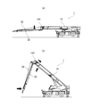
まず、ラフテレーンクレーン1の全体構成を説明する。ラフテレーンクレーン1は、図1に示すように、走行機能を有する車両の本体部分となる車体10と、車体10の四隅に設けられたアウトリガ11,・・・と、車体10に水平旋回可能に取り付けられた旋回台12と、旋回台12に立設されたブラケット13に取り付けられたブーム14と、を備えている。
まず、ラフテレーンクレーン1の全体構成を説明する。ラフテレーンクレーン1は、図1に示すように、走行機能を有する車両の本体部分となる車体10と、車体10の四隅に設けられたアウトリガ11,・・・と、車体10に水平旋回可能に取り付けられた旋回台12と、旋回台12に立設されたブラケット13に取り付けられたブーム14と、を備えている。
ブーム14は、先端ブーム143と、基端ブーム141と、それらの間の中間ブーム142、・・・と、によって入れ子式(テレスコープ式)に構成されている。基端ブーム141の下部とブラケット13との間には、起伏シリンダ15が架け渡されて、ブーム14全体が起伏できるようになっている。さらに、本実施例では、基端ブーム141の側面に、ジブ30及びテンションロッド20が横抱姿勢にて格納されている。
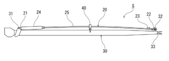
図2、3は、ジブ30を格納したジブ格納姿勢における、テンションロッド20及びジブ30を示している。ただし、以下の説明において、特に言及しない場合は「上方向/下方向」はジブ作業姿勢における方向で規定している。
テンションロッド20は、全体として長尺の棒状に形成される。テンションロッド20は、複数の取付孔を有する長さ調節部24と、中空の鋼管パイプからなる本体部25と、本体部25の先端側に配置されてジブ30のジブ先端連結部31に連結されるロッド先端連結部21と、本体部25の基端側に配置されてジブ格納姿勢においてジブ30のジブ基端連結部32に連結されるロッド基端連結部22と、テンションロッド20の基端近傍を把持するためのグリップ23と、を有している。
ロッド先端連結部21は、ジブ先端連結部31にピンを連通することで回動自在に取り付けられる。なお、ロッド先端連結部は、後述するようにジブ先端連結部としての長孔に摺動自在に支承され、チルトシリンダを伸縮することで摺動するように構成することもできる(実施例2参照)。
ジブ30は、全体として略Y字状に形成される。ジブ30の(ジブ作業時における)基端側は、先端ブーム143の先端のブームヘッド144(図1参照)下部の両側の係合部(不図示)と係合するように二股に分岐されており、分岐した先端にはU字状の係合部33が取り付けられている。ジブ30の先端側は、箱状構造となっており、その最先端に2枚のプレートが取り付けられてシーブが回転自在に挟持されている。
そして、本実施例のジブ30は、ロッド先端連結部21と連結されるジブ先端連結部31と、ジブ格納姿勢においてテンションロッド20の中間部を受けるコ字型のガイド部材40と、ロッド基端連結部22と連結されるジブ基端連結部32と、を有する。
ジブ先端連結部31は、図2、3に示すように、ジブ30の先端上部に配置されて、テンションロッド20のロッド先端連結部21とピンによって連結される。なお、ジブ先端連結部としては、後述するように、ロッド先端連結部をジブの軸線方向に摺動自在に支承する長穴を形成することもできる(実施例2参照)。
ジブ基端連結部32は、図2、3に示すように、ジブ30の基端上部に配置されて、テンションロッド20のロッド基端連結部22とピンによって連結される。後述するように、このジブ基端連結部32にロッド基端連結部22を連結するために、テンションロッド20のグリップ23を作業者が手で把持して押し下げる。ただし、テンションロッド20は中間部をガイド部材40で支持された状態で自重によって下方に撓んでいるため、下に押し下げる力は人力で十分な大きさである。
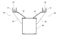
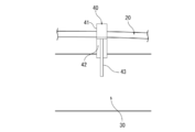
そして、ガイド部材40は、図4、5に示すように、全体としてジブ30から上方外側に突出する腕状に形成される。ガイド部材40は、テンションロッド20を受けるコ字部41と、コ字部41を支持する腕部42と、コ字部41及び腕部42を下方から支える補強部43と、を有している。
コ字部41は、ジブ作業姿勢において上向きに開くように、換言するとジブ30の反対方向に向いて開くように形成される。コ字部41のジブ30の幅方向の位置は、ジブ先端連結部31とジブ基端連結部32を結ぶ直線上にコ字部41の幅方向の中心が位置するように設定される。
そして、ガイド部材40のコ字部41のジブ30の上面からの高さは、ジブ先端連結部31とジブ基端連結部32を結ぶ直線よりも上方向(ジブ作業姿勢)に所定の距離だけ離れた位置とされる。すなわち、コ字部41の高さは、テンションロッド20がジブ30の下方に位置する反転姿勢において、テンションロッド20が自重によって撓んだとしても、テンションロッド20がコ字部41の底面部に押し付けられ固定されるように設定される。換言すると、あらかじめ反転姿勢におけるガイド部材40位置でのテンションロッド20全長の自重による撓み量(形状)を計算しておき、少なくとも、計算した撓み量よりも上方(使用姿勢、反転姿勢では下方)にコ字部41を配置すればよい。したがって、格納作業の途中でテンションロッド基端連結部22をジブ基端連結部32に連結する際には、ガイド部材40によって中間部を支持された状態で撓んでいるため、少なくとも反転状態との撓み量の差分に相当する分の力を手で加える必要がある。
なお、ガイド部材40の高さは、格納姿勢が下抱姿勢となる機種では、走行する場合の振動等を考慮すると、上述の撓み量に基づいて計算した高さに所定の余裕高さを加えることが好ましい。ただし、ガイド部材40の高さは、テンションロッド20のパイプ状の本体部25が弾性変形する範囲内で、かつ、手で押して連結できる程度とする必要がある。
(作用)
次に、図6~9を用いて、本実施例のテンションロッドの格納構造Sの作用について説明する。はじめに、図6(a)、(b)及び図7(c)、(d)、(e)を用いて、ジブ30を格納する全体手順について説明する。なお、ジブ30を格納姿勢から使用姿勢(張出姿勢)へと移行する手順は、概ね、以下の手順の逆順となる。
次に、図6~9を用いて、本実施例のテンションロッドの格納構造Sの作用について説明する。はじめに、図6(a)、(b)及び図7(c)、(d)、(e)を用いて、ジブ30を格納する全体手順について説明する。なお、ジブ30を格納姿勢から使用姿勢(張出姿勢)へと移行する手順は、概ね、以下の手順の逆順となる。
まず、図6(a)に示すように、ブーム14を略水平な状態まで倒し、テンションロッド20をブームヘッド144から取り外す。すなわち、ロッド先端連結部21は、ピンによってジブ先端連結部31に連結したまま、ロッド基端連結部22は、ピンを抜いてブームヘッド144から取り外す。そして、本実施例では、テンションロッド20の中間部をガイド部材40内に載置した状態で、テンションロッド20のグリップ23を把持して手で下向きに押して位置を合わせ、ロッド基端連結部22をジブ基端連結部32にピンによって連結する。
これとは逆に、ジブ30を張り出す際には、グリップ23を把持して手で下向きに押しつつ、ピンを抜きロッド基端連結部22をジブ基端連結部32から取り外すことでテンションロッド20の固定が解除される。すなわち、ガイド部材40は上部が開いているため、テンションロッド20の中間部において、従来のようなキャッチ部材の解除作業は必要ない。
次に、図6(b)に示すように、ブーム14を縮めながら、ブーム14を起こす。そうすると、ジブ30が自重によって回動して略垂直に立つ姿勢となる。
次に、図7(c)に示すように、ジブ30(及びテンションロッド20、20)に補助ワイヤ50を掛けてウインチで巻き上げることで、ジブ30をブーム14の下面まで引き寄せる。
次に、図7(d)に示すように、再びブーム14を略水平な状態まで倒し、ジブ30をブームヘッド144から取り外す。すなわち、ブーム14を倒した状態で、ジブ30の係合部33からピンを抜き、ブーム14を一時的に伸ばすことで、ジブ30とブームヘッド144の係合を外す。さらに、基端ブーム141の側面に配置したサイドアップシリンダ(不図示)をピンによってジブ30と連結する。
最後に、図7(e)に示すように、サイドアップシリンダを縮めることで、ジブ30を基端ブーム141の下面から、基端ブーム141の側面まで引き上げる。そして、ジブ30の適所を基端ブーム141に固定してジブ30の格納が完了する。
上述したように、図6(a)の工程では、ジブ30はブームヘッド144の前方に振り出されている。この状態では、ジブ30の上方にテンションロッド20が位置している。そして、この状態で、テンションロッド20の中間部をガイド部材40内に載置し、グリップ23を持って押し下げながら(弾性変形させながら)、テンションロッド20の基端連結部22がジブ30の基端連結部32とピンによって連結される。
図6(b)~図7(c)の工程では、ジブ30は、ブームヘッド144の下方に吊り下げられて立っている。この状態では、テンションロッド20の長さ方向に重力が作用するため、ガイド部材40からテンションロッド20が逸脱することはない。
図7(d)の工程では、ジブ30は、ブーム14下面に引き寄せられ、テンションロッド20が下でジブ30が上にある状態となっている。この状態では、ガイド部材40からテンションロッド20が逸脱する方向に重力が作用する。したがって、この状態はテンションロッド20が最も逸脱しやすい状態である。ただし、本実施例では、自重による撓み量を超えるようにガイド部材40の高さを設定しているため、この状態でもテンションロッド20の復元力によって、テンションロッド20の中間部はガイド部材40の底面部に押し付けられている。なお、格納姿勢が下抱姿勢となる機種では、工程に相違点はあるものの、テンションロッド20とジブ30の荷重関係は図9に示す状態と同じである。
次に、図7(e)の工程では、ジブ30は、ブーム14側面に引き寄せられて、テンションロッド20が外側でジブ30が内側にある状態となっている。そして、この状態が、横抱姿勢におけるジブ30及びテンションロッド20の格納姿勢となる。この状態では、図8に示すように、テンションロッド20の復元力はコ字部41の底壁を水平内向きに押す方向に作用し、かつ、テンションロッド20の自重はコ字部41の側壁を垂直下向きに押す方向に作用する。すなわち、復元力の作用方向と自重の作用方向とが略直交している。そして、自重はコ字部41の側壁によって受け、復元力はコ字部41の底壁で受けるようになっている。すなわち、テンションロッド20がコ字部41から逸脱する方向に力は作用しない。むしろ、テンションロッド20がコ字部41から逸脱することを妨げる方向に力が作用する。
(効果)
次に、本実施例のテンションロッドの格納構造Sの奏する効果を列挙して説明する。
次に、本実施例のテンションロッドの格納構造Sの奏する効果を列挙して説明する。
(1)上述してきたように、本実施例のテンションロッドの格納構造Sは、ジブ作業姿勢においてブーム14の先端上部とジブ30の先端適所の間に張設されるテンションロッドの格納構造Sである。そして、テンションロッドの格納構造Sは、ジブ30の先端適所に連結されるロッド先端連結部21と、ジブ格納姿勢においてジブ30の基端適所に連結されるロッド基端連結部22と、を有するテンションロッド20と;ロッド先端連結部21と連結されるジブ先端連結部31と、ジブ格納姿勢においてテンションロッド20の中間部を受けるコ字型のガイド部材40と、ロッド基端連結部22と連結されるジブ基端連結部32と、を有するジブ30と;を備えている。そして、ジブ格納姿勢において、ロッド先端連結部21がジブ先端連結部31と連結されるとともに、ロッド基端連結部22がジブ基端連結部32と連結された状態で、テンションロッド20の弾性変形による復元力によって、テンションロッド20の中間部がコ字型のガイド部材40に押し付けられるようになっている。このため、簡単な構成であり、ジブ30の張出作業の際にテンションロッド20の中間部での作業が必要とされないテンションロッドの格納構造Sとなる。
すなわち、テンションロッド20の撓みを利用することで、簡単な構造のガイド部材40によってテンションロッド20を格納・保持できる。さらに、ガイド部材40は上方が開いた構造であるため、ジブ30の張出作業の際に従来のようにキャッチ部材を解除する必要はない。
(2)また、テンションロッド20がジブ30よりも下方に位置する反転姿勢において、テンションロッド20が自重によってガイド部材40から逸脱しないように、テンションロッド20がコ字型のガイド部材40の底面部に押し付けられて固定されるように、ガイド部材40のジブ30からの高さが設定される。すなわち、格納作業においては、各工程によってジブ30の姿勢が変化する。そして、各工程中、テンションロッド20がジブ30よりも下方に位置する反転姿勢の荷重状態が、テンションロッド20がガイド部材40から最も逸脱しやすい荷重状態である。そこで、この最も逸脱しやすい荷重状態となる反転姿勢であっても、テンションロッド20がガイド部材40の外に出ないようにガイド部材40の高さを設定すれば、全工程においてテンションロッド20がガイド部材40から外れることを防止できる。具体的には、反転姿勢における自重による撓み量よりも、作業姿勢において高い位置にガイド部材40の底面部を配置すればよい。
(3)さらに、ジブ格納姿勢において、ジブ30は、ジブ作業姿勢におけるジブ30下面を基端ブーム141側面に引き寄せた横抱姿勢で保持されるように構成できる。この横抱姿勢では、テンションロッド20の自重はガイド部材40の側壁によって支持され、同時に、テンションロッド20の弾性変形による復元力はガイド部材40の底部を押す方向に作用する。すなわち、横抱姿勢では、テンションロッド20の弾性変形による復元力は、ガイド部材40からの逸脱を妨げる方向に作用するため、テンションロッド20がガイド部材40から逸脱することはない。さらに、テンションロッド20を撓ませてガタつきを抑えることにより、走行振動による接触音の発生を抑制できる。
(4)また、ジブ格納姿勢において、ジブ30は、ジブ作業姿勢におけるジブ30下面を基端ブーム141下面に引き寄せた下抱姿勢で保持されるように構成できる。この下抱姿勢では、テンションロッド20の自重は、テンションロッド20の弾性変形による復元力に対向する方向に作用する。しかしながら、テンションロッド20の中間部がコ字型のガイド部材40に押し付けられる程度の復元力を持たせることで、下抱姿勢でもテンションロッド20のガイド部材40からの逸脱を防止できる。
以下、図10、11を用いて、実施例1とは異なる形態のテンションロッドの格納構造Sについて説明する。なお、前記実施の形態で説明した内容と同一乃至均等な部分の説明については同一符号を付して説明する。
(構成)
はじめに構成について説明する。図10、11に示すように、本実施例のテンションロッドの格納構造Sは、実施例1と同様に、テンションロッド20と、ジブ60と、によって構成されている。ただし、実施例1と異なり、テンションロッド20は基端部が作業姿勢においてテンションロッド接続リンク145に接続され、先端部が作業姿勢及び格納姿勢においてサポート部材61に摺動自在に支承されるチルトシリンダ63に接続されている。
はじめに構成について説明する。図10、11に示すように、本実施例のテンションロッドの格納構造Sは、実施例1と同様に、テンションロッド20と、ジブ60と、によって構成されている。ただし、実施例1と異なり、テンションロッド20は基端部が作業姿勢においてテンションロッド接続リンク145に接続され、先端部が作業姿勢及び格納姿勢においてサポート部材61に摺動自在に支承されるチルトシリンダ63に接続されている。
テンションロッド20は、本体部25と、ジブ先端連結部31としてのサポート部材61に摺動自在に支承されるロッド先端連結部21と、ジブ格納姿勢においてジブ基端連結部62に連結され、ジブ作業姿勢においてテンションロッド接続リンク145に連結されるロッド基端連結部22と、を有している。そして、本実施例の2つのロッド先端連結部21、21は、サポート部材61に挿入されて摺動自在に支承される摺動軸26を介して相互に連結されている。
ジブ60は、ロッド先端連結部21どうしを連結する摺動軸26をジブ60の軸線方向に摺動自在に支承する、ジブ先端連結部としてのサポート部材61と、ジブ格納姿勢においてテンションロッド20の中間部を受けるコ字型のガイド部材40と、ジブ格納姿勢においてロッド基端連結部22と連結されるジブ基端連結部62と、ジブ60の軸線方向に伸縮してロッド先端連結部21を連結する摺動軸26を摺動させるチルトシリンダ63と、を備えている。サポート部材61は、側面に長孔を有しており、この長孔内に摺動軸26を摺動自在に支承する。
(作用)
次に、本実施例のテンションロッドの格納構造Sの作用について説明する。ジブ格納姿勢では、図10に示すように、ロッド先端連結部21どうしを連結する摺動軸26はサポート部材61内の基端寄りの位置に配置され、ロッド基端連結部22はジブ基端連結部62と連結され、テンションロッド20の中間部はコ字型のガイド部材40に押し付けられる。さらに、図11に示すように、ジブ作業姿勢では、ロッド先端連結部21どうしを連結する摺動軸26はサポート部材61内でチルトシリンダ63によって先端寄りの位置に移動され、ロッド基端連結部22はテンションロッド接続リンク145に連結され、テンションロッド20の中間部はガイド部材40から脱して上方に移動する。
次に、本実施例のテンションロッドの格納構造Sの作用について説明する。ジブ格納姿勢では、図10に示すように、ロッド先端連結部21どうしを連結する摺動軸26はサポート部材61内の基端寄りの位置に配置され、ロッド基端連結部22はジブ基端連結部62と連結され、テンションロッド20の中間部はコ字型のガイド部材40に押し付けられる。さらに、図11に示すように、ジブ作業姿勢では、ロッド先端連結部21どうしを連結する摺動軸26はサポート部材61内でチルトシリンダ63によって先端寄りの位置に移動され、ロッド基端連結部22はテンションロッド接続リンク145に連結され、テンションロッド20の中間部はガイド部材40から脱して上方に移動する。
そして、ジブ格納姿勢が下抱姿勢の場合には、図9に示すようにガイド部材40からテンションロッド20が逸脱する方向に重力が作用する。本実施例では、自重による撓み量を超えるようにガイド部材40の高さを設定しているため、この状態でもテンションロッド20の復元力によって、テンションロッド20の中間部はガイド部材40の底面部に押し付けられている。また、ジブ格納姿勢が横抱姿勢の場合には、図8に示すようにテンションロッド20の復元力はコ字部41の底壁を水平内向きに押す方向に作用し、かつ、テンションロッド20の自重はコ字部41の側壁を垂直下向きに押す方向に作用する。この状態ではテンションロッド20の復元力は、テンションロッド20がコ字部41から逸脱することを妨げる方向に力が作用する。
(効果)
次に、本実施例のテンションロッドの格納構造Sの奏する効果を説明する。
次に、本実施例のテンションロッドの格納構造Sの奏する効果を説明する。
(1)上述してきたように、本実施例のテンションロッドの格納構造Sは、実施例1と同様に、テンションロッド20とジブ60とを備え、ジブ格納姿勢において、ロッド先端連結部21がジブ先端連結部としてのサポート部材61と連結されるとともに、ロッド基端連結部22がジブ基端連結部62と連結された状態で、テンションロッド20の弾性変形による復元力によって、テンションロッド20の中間部がコ字型のガイド部材40に押し付けられるようになっている。このため、簡単な構成であり、ジブ60の張出作業の際にテンションロッド20の中間部での作業が必要とされないテンションロッドの格納構造Sとなる。
(2)そして、本実施例のテンションロッドの格納構造Sでは、ブーム14の先端のブームヘッド145に、作業姿勢においてロッド基端連結部22と連結されるテンションロッド接続リンク145が取り付けられている。ジブ60は、ロッド先端連結部21をジブ60の軸線方向に摺動自在に支承する、ジブ先端連結部としてのサポート部材61と、ジブ60の軸線方向に伸縮してロッド先端連結部21を摺動させるチルトシリンダ63と、を有している。そして、ジブ格納姿勢において、ロッド先端連結部21はサポート部材61内の基端寄りの位置に配置されるとともに、ロッド基端連結部22がジブ基端連結部62と連結された状態で、テンションロッド20の弾性変形による復元力によって、テンションロッド20の中間部がコ字型のガイド部材40に押し付けられるようになっている。さらに、ジブ作業姿勢において、ロッド先端連結部21はチルトシリンダ63を伸縮することでサポート部材61内を摺動移動されて所定位置に配置されるとともに、ロッド基端連結部22はテンションロッド接続リンク145と連結されるようになっている。このように、本実施例のテンションロッドの格納構造Sは、実施例1とは異なる形態のテンションロッド20及びジブ60に適用できる。この際、実施例1と同様、テンションロッド20の撓みを利用することで、簡単な構造のガイド部材40によってテンションロッド20を格納・保持できる。さらに、ガイド部材40は上方が開いた構造であるため、ジブ60の張出作業の際に従来のようにキャッチ部材を解除する必要はない。さらに、ジブ張出時のキャッチ部材の解除忘れによるテンションロッド20の損傷を防ぐ効果もある。
そして、上述した構成であれば、ジブ張出作業においてブーム上側のテンションロッド接続が不要になる、高所作業をなくして低位置での安全な作業を実現できる、省スペースでの張出が可能で、張出・格納時間も大幅に短縮できる、といった効果を奏する。
なお、この他の構成および作用効果については、前記実施の形態と略同様であるため説明を省略する。
以上、図面を参照して、本発明の実施例を詳述してきたが、具体的な構成は、この実施例に限らず、本発明の要旨を逸脱しない程度の設計的変更は、本発明に含まれる。
例えば、実施例では、「コ字型」のガイド部材40は、底壁と側壁とが略直交するコ字型である場合について説明したが、これに限定されるものではなく、先端が開いたコ字型であってもよいし、底壁が湾曲したU字状なども含まれる。換言すると、本発明における「コ字型」は、ジブ作業姿勢で上になる一辺が開いているオープンな形状であることを意図したものであり、厳密な意味で「コ」の形状とすることを意図するものではない。
また、実施例では、ガイド部材40がテンションロッド20の長さ方向に1か所だけ配置される場合について説明したが、これに限定されるものではない。ガイド部材40は、例えば2か所など、複数の位置に配置することもできる。
S テンションロッドの格納構造
1 ラフテレーンクレーン
14 ブーム
141 基端ブーム
143 先端ブーム
144 ブームヘッド
145 テンションロッド接続リンク
20 テンションロッド
21 ロッド先端連結部
22 ロッド基端連結部
23 グリップ
26 摺動軸
30 ジブ
31 ジブ先端連結部
32 ジブ基端連結部
40 ガイド部材
41 コ字部
42 腕部
43 補強部
60 ジブ
61 サポート部材(ジブ先端連結部)
62 ジブ基端連結部
63 チルトシリンダ
1 ラフテレーンクレーン
14 ブーム
141 基端ブーム
143 先端ブーム
144 ブームヘッド
145 テンションロッド接続リンク
20 テンションロッド
21 ロッド先端連結部
22 ロッド基端連結部
23 グリップ
26 摺動軸
30 ジブ
31 ジブ先端連結部
32 ジブ基端連結部
40 ガイド部材
41 コ字部
42 腕部
43 補強部
60 ジブ
61 サポート部材(ジブ先端連結部)
62 ジブ基端連結部
63 チルトシリンダ
Claims (5)
- ジブ作業姿勢においてブームの先端上部とジブの先端適所の間に張設されるテンションロッドの格納構造であって、
前記ジブの先端適所に連結されるロッド先端連結部と、ジブ格納姿勢において前記ジブの基端適所に連結されるロッド基端連結部と、を有するテンションロッドと;
前記ロッド先端連結部と連結されるジブ先端連結部と、ジブ格納姿勢において前記テンションロッドの中間部を受けるコ字型のガイド部材と、前記ロッド基端連結部と連結されるジブ基端連結部と、を有するジブと;を備え、
ジブ格納姿勢において、前記ロッド先端連結部が前記ジブ先端連結部と連結されるとともに、前記ロッド基端連結部が前記ジブ基端連結部と連結された状態で、前記テンションロッドの弾性変形による復元力によって、前記テンションロッドの中間部が前記コ字型のガイド部材に押し付けられるようになっている、テンションロッドの格納構造。 - 前記テンションロッドが前記ジブよりも下方に位置する反転姿勢において、前記テンションロッドが前記コ字型ガイド部材の底面部に押し付けられ固定されるようになっている、請求項1に記載されたテンションロッドの格納構造。
- ジブ格納姿勢において、前記ジブは、ジブ作業姿勢におけるジブ下面を前記ブーム側面に引き寄せた横抱姿勢で保持されるようになっている、請求項1又は請求項2に記載されたテンションロッドの格納構造。
- ジブ格納姿勢において、前記ジブは、ジブ作業姿勢におけるジブ下面を前記ブーム下面に引き寄せた下抱姿勢で保持されるようになっている、請求項1又は請求項2に記載されたテンションロッドの格納構造。
- 前記ブームの先端には、前記ロッド基端連結部と連結されるテンションロッド接続リンクが取り付けられ、
前記ジブは、前記ロッド先端連結部を前記ジブの軸線方向に摺動自在に支承する、前記ジブ先端連結部としてのサポート部材と、前記ジブの軸線方向に伸縮して前記ロッド先端連結部を摺動させるチルトシリンダと、を有し、
ジブ格納姿勢において、前記ロッド先端連結部は前記サポート部材内の基端寄りの位置に配置されるとともに、前記ロッド基端連結部が前記ジブ基端連結部と連結された状態で、前記テンションロッドの弾性変形による復元力によって、前記テンションロッドの中間部が前記コ字型のガイド部材に押し付けられるようになっており、
ジブ作業姿勢において、前記ロッド先端連結部は前記チルトシリンダを伸縮することで前記サポート部材内を摺動移動されて所定位置に配置されるとともに、前記ロッド基端連結部は前記テンションロッド接続リンクと連結されるようになっている、請求項1乃至請求項4のいずれか一項に記載されたテンションロッドの格納構造。
Applications Claiming Priority (2)
| Application Number | Priority Date | Filing Date | Title |
|---|---|---|---|
| JP2015084345A JP6536145B2 (ja) | 2015-04-16 | 2015-04-16 | テンションロッドの格納構造 |
| JP2015-084345 | 2015-04-16 |
Publications (1)
| Publication Number | Publication Date |
|---|---|
| WO2016167027A1 true WO2016167027A1 (ja) | 2016-10-20 |
Family
ID=57126442
Family Applications (1)
| Application Number | Title | Priority Date | Filing Date |
|---|---|---|---|
| PCT/JP2016/055372 Ceased WO2016167027A1 (ja) | 2015-04-16 | 2016-02-24 | テンションロッドの格納構造 |
Country Status (2)
| Country | Link |
|---|---|
| JP (1) | JP6536145B2 (ja) |
| WO (1) | WO2016167027A1 (ja) |
Citations (5)
| Publication number | Priority date | Publication date | Assignee | Title |
|---|---|---|---|---|
| JPS5953397A (ja) * | 1982-09-21 | 1984-03-28 | 株式会社神戸製鋼所 | ホイール式クレーンのジブ張出し、格納装置 |
| JPH0930778A (ja) * | 1995-07-12 | 1997-02-04 | Tadano Ltd | ジブ付きクレーン車におけるジブのテンション装置 |
| JPH10245190A (ja) * | 1997-03-04 | 1998-09-14 | Kato Works Co Ltd | テンションロッド |
| JP2000318979A (ja) * | 1999-05-11 | 2000-11-21 | Tadano Ltd | 補助ジブ付移動式クレーン装置 |
| JP2007191250A (ja) * | 2006-01-17 | 2007-08-02 | Tadano Ltd | 移動式クレーンのジブ張出装置 |
-
2015
- 2015-04-16 JP JP2015084345A patent/JP6536145B2/ja active Active
-
2016
- 2016-02-24 WO PCT/JP2016/055372 patent/WO2016167027A1/ja not_active Ceased
Patent Citations (5)
| Publication number | Priority date | Publication date | Assignee | Title |
|---|---|---|---|---|
| JPS5953397A (ja) * | 1982-09-21 | 1984-03-28 | 株式会社神戸製鋼所 | ホイール式クレーンのジブ張出し、格納装置 |
| JPH0930778A (ja) * | 1995-07-12 | 1997-02-04 | Tadano Ltd | ジブ付きクレーン車におけるジブのテンション装置 |
| JPH10245190A (ja) * | 1997-03-04 | 1998-09-14 | Kato Works Co Ltd | テンションロッド |
| JP2000318979A (ja) * | 1999-05-11 | 2000-11-21 | Tadano Ltd | 補助ジブ付移動式クレーン装置 |
| JP2007191250A (ja) * | 2006-01-17 | 2007-08-02 | Tadano Ltd | 移動式クレーンのジブ張出装置 |
Also Published As
| Publication number | Publication date |
|---|---|
| JP6536145B2 (ja) | 2019-07-03 |
| JP2016204066A (ja) | 2016-12-08 |
Similar Documents
| Publication | Publication Date | Title |
|---|---|---|
| JP6151606B2 (ja) | カウンタウエイト位置調整機構 | |
| JP6578749B2 (ja) | ジブ張出格納機構 | |
| JP6569311B2 (ja) | ジブ張出格納機構 | |
| WO2016167027A1 (ja) | テンションロッドの格納構造 | |
| JP5816225B2 (ja) | 多段伸縮アーム装置および多段伸縮アーム装置を備えた深掘り掘削機 | |
| JP7326043B2 (ja) | 建設機械 | |
| JP4810291B2 (ja) | クレーン | |
| JP5547618B2 (ja) | クレーン | |
| JP6388089B2 (ja) | クレーン | |
| JP4191955B2 (ja) | クレーン装置のジブ格納機構 | |
| JP2018203487A (ja) | 建設機械 | |
| JP6778415B2 (ja) | 移動式クレーン | |
| JP5352164B2 (ja) | クレーン装置のジブ張出し格納装置 | |
| JP2018065662A (ja) | 作業機械におけるシリンダ固定装置、および、作業機械におけるシリンダ固定方法 | |
| JP2016216205A (ja) | クレーンおよびクレーン構成部材の取り外し方法 | |
| JP3204446U (ja) | ジブ連結構造 | |
| JP2020033192A (ja) | クレーン | |
| JP5352165B2 (ja) | クレーン装置のジブ張出し格納装置 | |
| JP5530806B2 (ja) | ジブ張出し装置 | |
| JP2020066516A (ja) | ジブ起伏機構およびジブ起伏機構を備えたクレーン車 | |
| JP2018162125A (ja) | タワークレーン | |
| WO2018052050A1 (ja) | クレーン | |
| JP4964520B2 (ja) | クレーン車のジブ起伏操作用伸縮シリンダの格納装置 | |
| JP3216178U (ja) | 墜落防止装置 | |
| JP2015124026A (ja) | ブーム脱着構造 |
Legal Events
| Date | Code | Title | Description |
|---|---|---|---|
| 121 | Ep: the epo has been informed by wipo that ep was designated in this application |
Ref document number: 16779819 Country of ref document: EP Kind code of ref document: A1 |
|
| NENP | Non-entry into the national phase |
Ref country code: DE |
|
| 122 | Ep: pct application non-entry in european phase |
Ref document number: 16779819 Country of ref document: EP Kind code of ref document: A1 |