WO2016166969A1 - 弾性クローラおよび弾性クローラ駆動機構 - Google Patents
弾性クローラおよび弾性クローラ駆動機構 Download PDFInfo
- Publication number
- WO2016166969A1 WO2016166969A1 PCT/JP2016/001989 JP2016001989W WO2016166969A1 WO 2016166969 A1 WO2016166969 A1 WO 2016166969A1 JP 2016001989 W JP2016001989 W JP 2016001989W WO 2016166969 A1 WO2016166969 A1 WO 2016166969A1
- Authority
- WO
- WIPO (PCT)
- Prior art keywords
- elastic
- elastic crawler
- pin member
- sprocket
- pressure receiving
- Prior art date
- Legal status (The legal status is an assumption and is not a legal conclusion. Google has not performed a legal analysis and makes no representation as to the accuracy of the status listed.)
- Ceased
Links
Images



Classifications
-
- B—PERFORMING OPERATIONS; TRANSPORTING
- B62—LAND VEHICLES FOR TRAVELLING OTHERWISE THAN ON RAILS
- B62D—MOTOR VEHICLES; TRAILERS
- B62D55/00—Endless track vehicles
- B62D55/08—Endless track units; Parts thereof
- B62D55/18—Tracks
- B62D55/24—Tracks of continuously flexible type, e.g. rubber belts
- B62D55/242—The flexible band being semi-rigid for resisting back-flexing and contributing to spring the vehicle
-
- B—PERFORMING OPERATIONS; TRANSPORTING
- B62—LAND VEHICLES FOR TRAVELLING OTHERWISE THAN ON RAILS
- B62D—MOTOR VEHICLES; TRAILERS
- B62D55/00—Endless track vehicles
- B62D55/08—Endless track units; Parts thereof
- B62D55/12—Arrangement, location, or adaptation of driving sprockets
- B62D55/125—Final drives
-
- B—PERFORMING OPERATIONS; TRANSPORTING
- B62—LAND VEHICLES FOR TRAVELLING OTHERWISE THAN ON RAILS
- B62D—MOTOR VEHICLES; TRAILERS
- B62D55/00—Endless track vehicles
- B62D55/08—Endless track units; Parts thereof
- B62D55/18—Tracks
- B62D55/24—Tracks of continuously flexible type, e.g. rubber belts
- B62D55/253—Tracks of continuously flexible type, e.g. rubber belts having elements interconnected by one or more cables or like elements
Definitions
- the present invention relates to an elastic crawler and an elastic crawler driving mechanism.
- Some elastic crawlers have a plurality of engaging portions (drive protrusions) on the inner peripheral side that can be engaged with a plurality of pin members (meshing portions) arranged at intervals in the circumferential direction of the sprocket. Yes (see, for example, Patent Document 1).
- the elastic crawler driving mechanism described in Patent Document 1 has a large circumferential interval (gap) between the pin members arranged on the sprocket, so there is no risk of tooth skipping due to mud or the like.
- the pin member is formed with an isosceles portion having a widened angle in the radial direction so that the pin member of the sprocket and the engaging portion of the elastic crawler By making the surface contact, durability of the engaging portion is improved.
- the above-mentioned elastic crawler has an isosceles triangular shape in the side view, and the inclined surface is only in surface contact with the isosceles portion formed on the pin member.
- the interference between the pin member and the engaging portion is large, and there is room for improvement in improving the durability of the engaging portion.
- An object of the present invention is to provide an elastic crawler and an elastic crawler driving mechanism that improve the durability of the engaging portion while suppressing interference between the pin member and the engaging portion.
- the elastic crawler according to the present invention is an elastic crawler having a plurality of engaging portions on the inner peripheral side that can be engaged with each of a plurality of pin members arranged at intervals in the circumferential direction of the sprocket,
- the engaging portion has a pressure receiving surface that receives the pin member on the base side of the engaging portion, and the pressure receiving surface has a rolling diameter whose profile in side view is defined by the following formula (1): It is characterized in that it is formed by an envelope drawn by the outer edge of the pin member when the sprocket rolls on a plane together with the virtual rotating body coaxially with the central axis of the virtual rotating body of D 1 .
- D 1 D 0 ⁇ a (1)
- D 0 (pitch of the engaging portion) ⁇ (number of pin members) / (circumference ratio), and 0.9 ⁇ a ⁇ 1
- the elastic crawler according to the present invention preferably satisfies the condition of 0.94 ⁇ a ⁇ 0.98 in the equation (1). In this case, interference between the pin member and the engaging portion can be more reliably suppressed.
- the engaging portion has a flank for avoiding interference with the pin member on a distal end side of the engaging portion, and the flank is a contour in a side view.
- An envelope drawn by the outer edge of the pin member when the sprocket rolls on the plane together with the virtual rotating body, the shape of which is coaxial with the central axis of the virtual rotating body having a rolling diameter D 2 defined by the following equation (2) Preferably it is shaped with a line.
- D 2 D 0 ⁇ b (2)
- 1 ⁇ b ⁇ 1.1 In this case, the durability of the engaging portion can be further improved while suppressing interference between the pin member and the engaging portion.
- the elastic crawler according to the present invention preferably satisfies the condition of 1.00 ⁇ b ⁇ 1.03 in the expression (2).
- the volume of the engaging portion can be kept large while suppressing interference between the pin member and the engaging portion during braking or downhill traveling.
- a connecting portion of the pressure receiving surface and the flank surface has a curved contour shape in a side view.
- the engagement operation and the release operation of the pin member and the engagement portion can be smoothly performed by smoothly connecting the pressure receiving surface and the flank surface at the connection portion.
- connection portion between the pressure receiving surface and the flank is such that the height from the inner peripheral surface of the endless belt-like body portion is 25% or more and 60% or less of the total height of the engaging portion. It is preferable that In this case, the durability of the engaging portion can be improved while more reliably suppressing interference between the pin member and the engaging portion.
- An elastic crawler driving mechanism includes any one of the elastic crawlers described above and a sprocket in which a plurality of pin members are arranged at intervals in the circumferential direction. According to the elastic crawler driving mechanism according to the present invention, it is possible to improve the durability of the engaging portion while suppressing interference between the pin member and the engaging portion.
- an elastic crawler and an elastic crawler drive mechanism that improve the durability of the engaging portion while suppressing interference between the pin member and the engaging portion.
- FIG. 1 It is an expansion perspective view showing typically an elastic crawler and an elastic crawler drive mechanism concerning an embodiment of the present invention in a partial section. It is an enlarged side view which shows typically the elastic crawler drive mechanism of FIG.
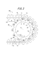
- FIG. 2 is an enlarged side view schematically showing an elastic protrusion provided on the elastic crawler in FIG. 1;
- the elastic crawler driving mechanism of FIG. 1 the behavior of the pin member when the sprocket rotates in one direction and the pin member engages with the elastic protrusion is illustrated.
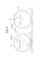
- FIG. 1 For explaining a method of drawing a cycloid curve used for calculating first and second envelopes for defining the contour shape of an elastic protrusion in an elastic crawler and an elastic crawler driving mechanism according to an embodiment of the present invention.
- the circumferential direction of the elastic crawler has the same meaning as the circumferential direction of the endless strip
- the width direction has the same meaning as the width of the elastic crawler (endless strip).
- the side surface is synonymous with the side surface of the elastic crawler (endless belt-like body).
- reference numeral 100 denotes an elastic crawler driving mechanism according to an embodiment of the present invention.
- Reference numeral 10 denotes an elastic crawler according to an embodiment of the present invention.
- the elastic crawler 10 has an endless belt-like body 11.
- the endless belt-like body 11 is an annular member having no end.
- a main cord layer 12 is disposed inside the endless strip 11.
- the main cord layer 12 is formed by, for example, arranging a plurality of steel cords 12 a that circulate around the endless belt 11 at intervals in the width direction.
- the endless belt-like body 11 is vulcanized and molded from a rubber material, for example.
- the elastic crawler 10 is provided with a plurality of lugs 13 on the outer peripheral side thereof.
- the lugs 13 are arranged at intervals in the circumferential direction of the endless strip 11.
- the lug 13 protrudes from the outer peripheral surface 11a of the endless strip 11 and extends in the width direction.
- the elastic crawler 10 has a plurality of elastic protrusions (engagement portions) 14 disposed on the inner peripheral side thereof.
- the elastic protrusions 14 are arranged at intervals in the circumferential direction of the endless strip 11.
- the elastic protrusions 14 protrude from the inner peripheral surface 11 b of the endless strip 11, and are arranged in pairs near the center in the width direction of the endless strip 11 with an interval in the width direction.
- the lug 13 and the elastic protrusion 14 can be vulcanized and formed integrally with the endless belt 11 or can be assembled separately by bonding or the like.
- Reference numeral 20 denotes a sprocket with which the elastic protrusion 14 of the elastic crawler 10 is engaged.
- the sprocket 20 has a plurality of pin members 22 spanned around the central axis O 1 of the sprocket 20 at intervals in the circumferential direction between two annular bodies 21 arranged at intervals in the width direction. Yes.
- the sprocket 20 has a space between two ring bodies 21 (not shown in FIG. 1 for the ring body 21 on the back side of the drawing) arranged at an interval in the width direction, and the two ring bodies 21.
- the ring body 21 has one intermediate body 23 that is disposed at an interval in the width direction, and a plurality of pin members 22 that are spanned between the ring body 21 and the intermediate body 23.
- the pin members 22 are arranged around the central axis O 1 of the sprocket 20 at intervals in the circumferential direction.
- Each of the pin members 22 sequentially enters between the elastic protrusions 14 of the elastic crawler 10 by the rotation of the sprocket 20, and then engages with one elastic protrusion 14 to press the elastic protrusion 14 in the rotation direction of the sprocket 20.
- the elastic crawler driving mechanism 100 can drive the elastic crawler 10 by transmitting the rotation of the sprocket 20 to the elastic crawler 10.
- the pin member 22 and the elastic protrusion 14 rotate at the same speed.
- the locus drawn by the rotation center axis O 2 of the pin member 22 is a cycloid curve when the sprocket 20 is rotated on the plane, and an envelope drawn by the outer edge of the pin member 22 at this time is drawn.
- the locus of the outer edge of the pin member 22 can be drawn. For this reason, if the outline shape in the side view of the elastic protrusion is formed by the envelope, the shape is adapted to the locus of the pin member 22.
- the pin member 22 when driving the elastic crawler 10 by rotating the sprocket 20, the pin member 22 is not engaged with the elastic protrusion 14 at the start of winding with the elastic crawler 10, but the pin member 22 is As it rotates, it approaches the elastic protrusion 14 on the front side in the rotation direction, and then engages with the elastic protrusion 14 when the winding is completed. That is, when the sprocket 20 is rotated to drive the elastic crawler 10, it can be said that the pin member 22 is rotating relatively faster than the elastic protrusion 14, and in this case, the diameter of the rotating body for drawing the cycloid curve Can be approximated to the actual trajectory of the pin member 22.
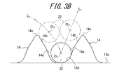
- FIG. 3A shows an outline shape in a side view when the elastic protrusion 14 of the elastic crawler 10 is viewed from the side.
- the elastic protrusion 14 has a pressure receiving surface 14 a that receives the pin member 22 on the base side.
- Pressure-receiving surface 14a is the contour shape in a side view, in the following virtual rotary body 20a of the rolling diameter D 1 defined by Equation (1) central axis O 3 and sprocket 20 coaxially of (in this embodiment, "Watai 21 ”) is formed by the first envelope L 1 drawn by the outer edge of the pin member 22 when it rolls on the plane F together with the virtual rotating body 20a.
- D 1 D 0 ⁇ a (1)
- D 0 (pitch P of the elastic protrusions 14) ⁇ (number of pin members 22) / (circumferential ratio ⁇ ), and 0.9 ⁇ a ⁇ 1
- D 0 is a reference diameter for obtaining the rolling diameter D 1 of the virtual rotating body 20a.
- the pitch P of the elastic protrusions 14 is a pitch between the apexes 14c of the elastic protrusions 14 when the elastic crawler 10 (endless belt-like body 11) is extended horizontally.
- the pitch P can be expressed in units of mm, for example.
- the number of pin members 22 is the number of pin members 22 arranged in the circumferential direction. In the present embodiment, as shown in FIG. 2, the number of pin members 22 is twelve.
- the reference diameter D 0 is substantially equal to the diameter of a virtual circle connecting the vertexes 14c of the elastic protrusions 14 when the elastic crawler 10 is wound around the sprocket 20 and assumed to be an annular body.
- a is a numerical value set in advance so as to satisfy the condition of 0.9 ⁇ a ⁇ 1. That is, in this embodiment, the rolling diameter D 1 of the virtual rotating body 20a is smaller than the reference diameter D 0 . In the present invention, it is preferable to take any numerical value within the range of 0.94 ⁇ a ⁇ 0.98.
- the central axis O 3 of the center axis O 1 and the virtual rotary body 20a of the sprocket 20 is assumed to have fixed coaxially plane F sprocket 20 with virtual rotator 20a It shows a cycloid C 1 of the pin member 22 when rolled up.
- the virtual rotating body 20a having the rolling diameter D 1 calculated from the above equation (1) is indicated by a broken line, and the actual sprocket 20 is indicated by a solid line.
- the sprocket 20 is arranged coaxially with the central axis O 1 of the virtual rotator 20a, and the sprocket 20 rolls on the plane F integrally with the virtual rotator 20a. This is a locus drawn by the rotation center axis O 2 .
- the pressure receiving surface 14a of the elastic projections 14, the contour shape in a side view is shaped in the first envelope L 1.
- the first envelope L 1 is a line drawn by the outer edge of the pin member 22 when the sprocket 20 rolls on the plane F together with the virtual rotating body 20a.
- the first envelope L 1 plots the pin member 22 moving along the cycloid curve C 1 in time series, and the pin member 22 engages with the elastic protrusion 14. It is the line which tied the engagement side outermost edge 22e.
- the cycloid curve C 1 has a virtual rotating body 20 a as shown on the right side of FIG. 4, starting from the position where the pin member 22 is arranged at the lowest point. It is drawn by rolling the sprocket 20 together.
- the contour shape of the pressure receiving surface 14a has an arbitrary length based on the lowest point of the cycloid curve C 1 extending from the lowest point shown on the left side of FIG. 4 toward the right side of FIG. It is formed by the first envelope L 1 drawn by the engagement side outermost edge 22e of the pin member 22 according to the cycloid curve C 1 .
- the arbitrary length said here is the length which can be set suitably according to the specification etc. of the elastic crawler 10.
- the arbitrary length is a length until the height from the tangent line F ′ of the sprocket 20 to the height h becomes parallel to the plane F.
- the pin member 22 engages with the elastic protrusion 14 when the winding with the elastic crawler 10 is completed, contrary to the driving.
- the elastic crawler 10 enters between the two elastic protrusions 14 while approaching the elastic protrusion 14 on the rear side in the rotation direction. That is, contrary to driving, when the sprocket 20 is driven by the elastic crawler 10, it can be said that the elastic protrusion 14 rotates relatively faster than the pin member 22, and in this case, for drawing a cycloid curve.
- By increasing the diameter of the rotating body it is possible to approximate the actual locus of the pin member 22.
- the elastic protrusion 14 has a flank 14 b for avoiding interference with the pin member 22 on the tip side.
- the flank 14b has a spline 20 (in the present embodiment, “ring body”) that is concentric with the central axis O 3 of the virtual rotating body 20b having a rolling diameter D 2 defined by the following formula (2). 21 ”) is formed by the second envelope L 2 drawn by the outer edge of the pin member 22 when it rolls on the plane F together with the virtual rotating body 20b.
- D 2 D 0 ⁇ b (2)
- D 0 (pitch P of the elastic protrusions 14) ⁇ (number of pin members 22) / (circumferential ratio ⁇ ), and 1 ⁇ b ⁇ 1.1
- D 0 is a reference diameter obtained by the same method as in the above-described equation (1).
- b is a numerical value set in advance so as to satisfy the condition of 1 ⁇ b. That is, in this embodiment, the rolling diameter D 2 of the imaginary rotating body 20b is larger in size than the reference diameter D 0. In the present invention, it is preferable to take an arbitrary numerical value within a range of 1.00 ⁇ b ⁇ 1.03.
- the sprocket 20 is virtual shows a cycloid curve C 2 of the pin member 22 when rolled on a plane F with the rotating member 20b.
- the virtual rotating body 20b having the rolling diameter D 2 calculated from the above equation (2) is indicated by a broken line, and the actual sprocket 20 is indicated by a solid line.
- the sprocket 20 is arranged coaxially with the central axis O 3 of the virtual rotator 20b, and the sprocket 20 rolls on the plane F integrally with the virtual rotator 20b. This is a locus drawn by the rotation center axis O 2 .
- flank 14b of the elastic projections 14 the contour shape in a side view is shaped in the second envelope L 2.
- the second envelope L 2 is a line drawn by the outer edge of the pin member 22 when the sprocket 20 rolls on the plane F together with the virtual rotator 20b.
- the second envelope L 2 plots the pin member 22 moving along the cycloid curve C 2 in time series, and the pin member 22 engages with the elastic protrusion 14. It is the line which tied the engagement side outermost edge 22e.
- the cycloid curve C 2 has a virtual rotating body 20b as shown on the right side of FIG. It is drawn by rolling the sprocket 20 together.
- the contour shape of the flank 14b follows a cycloid curve C 2 of any length among the cycloid curves C 2 extending from the lowest point shown on the left side of FIG. 4 toward the right side of FIG. It is formed by an envelope L 2 drawn by the outer edge of the member 22.
- the arbitrary length mentioned here may be any length that can be set as appropriate according to the specifications of the elastic crawler.
- the length is an arbitrary length based on the value of the cycloid curve C 2 parallel to the plane F until the height from the tangent line F ′ of the sprocket 20 reaches the height h.
- the flank 14 b of the elastic protrusion 14 is formed between the pin member 22 and the two elastic protrusions 14. Since the shape is close to the ideal locus of the pin member 22 until the start of entry, the pin member 22 will enter between the two elastic projections 14 when the pin member 22 and the elastic projection 14 are engaged.
- the pin member 22 is detached from the elastic protrusion 14 in order to prevent the elastic protrusion 14 from being caught and the pin member 22 is disengaged from the elastic protrusion 14, It is possible to set the volume of the elastic protrusion 14 as large as possible while preventing it from being caught on the surface.
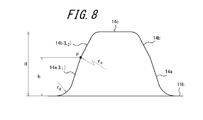
- the height h corresponds to the height of the connecting portion P between the pressure receiving surface 14a and the flank 14b.
- the height h is preferably 25% or more and 60% or less of the total height H of the elastic protrusion 14.
- the effects of the pressure receiving surface 14a and the flank 14b can be achieved in a more ideal form, and the volume of the elastic protrusion 14 can be set as large as possible.
- connection part P of the pressure receiving surface 14a and the flank 14b is formed in the shape of the outline in a side view.
- the connecting portion P by a large radius of curvature r p, and connects smoothly the pressure receiving surface 14a and the flank 14b.
- the release operation from the start of releasing the engagement with the elastic protrusion 14 to the completion of the release can be performed smoothly.
- the two flank surfaces 14b of the elastic protrusions 14 are connected via a top surface 14c extending in the width direction of the elastic crawler 10.
- the top surface 14 c is curved so as to be convex toward the outside of the elastic protrusion 14.
- a concave surface 14 d is formed between the inner peripheral surface 11 b of the endless belt 11 and the pressure receiving surface 14 at the base portion of the elastic protrusion 14.
- Concave 14d is the contour shape in a side view, is shaped in a curve made up of the radius of curvature r d.
- the curvature radius r d is preferably the diameter of the pin member 22.
- the elastic protrusion 14 has a symmetrical shape in side view with a line Y orthogonal to the inner peripheral surface 11 b of the endless strip 11 interposed therebetween. .
- the space between the two elastic protrusions 14 is secured widely, Only one elastic protrusion 14 is engaged.
- the pin member 22 rotates in advance of the elastic crawler 10, so that the region A in FIG. Then, the entry between the two elastic protrusions 14 is started.
- the pin member 22 approaches the elastic protrusion 14 on the front side in the rotation direction (the elastic protrusion 14 on the right side of the drawing in FIG.
- the pin member 22 moves the elastic protrusion 14 on the front side in the rotation direction (in FIG. 2, the elastic protrusion 14 on the left side of the region C in the drawing) in the rotation direction (in FIG. ), The engagement of the elastic protrusion 14 with the pressure receiving surface 14a is released.
- the pin member 22 is Since the elastic projection 14 is separated from the elastic projection 14 along the pressure-receiving surface 14a, the elastic projection 14 is extraneous with the elastic projection 14 when engaging the elastic projection 14 and transmitting the force to the elastic projection 14 while setting the volume of the elastic projection 14 as large as possible.
- the pin member 22 is disengaged from the pressure receiving surface 14a of the elastic protrusion 14 so as to release the engagement with the elastic protrusion 14, excessive interference with the elastic protrusion 14 is suppressed.
- the pin member 22 does not engage the elastic protrusion 14 in the region B in FIG. 2 when traveling on a downhill or during braking such as engine braking.
- the pin member 22 is moved toward the elastic protrusion 14 on the rear side in the rotational direction (in FIG. 3B, 2 as indicated by a two-dot chain line C 2 ).
- the two approach the two driving projections 14 while approaching the elastic projection 14) on the left side of the drawing.
- the pin member 22 since the shape of flank 14b of the elastic projections 14 along the second envelope L 2 as the profile of the outer edge of the pin member 22, as shown on the left side of FIG. 3B, the pin member 22 is Since it can pass through the flank 14b, it is possible to prevent the pin member 22 from being caught by the tip portion of the elastic protrusion 14 while setting the volume of the elastic protrusion 14 as large as possible.
- the pressure receiving surface 14a is the contour shape in a side view, the center of the virtual rotary member 20a of the rolling diameter D 1 defined by Equation (1) described above
- the sprocket 20 is coaxial with the axis O 3 and is formed by a first envelope L 1 drawn by the outer edge of the pin member 22 when the sprocket 20 rolls on the plane F together with the virtual rotator 20a.
- the contour shape of the pressure receiving surface 14a becomes a shape close to the locus of the pin member 22 from when it is engaged with the pin member 22 until it is pushed out by the pin member 22, so that the pin member 22 and the elastic protrusion 14 are
- the durability of the elastic protrusion 14 can be improved while suppressing the interference between the pin member 22 and the elastic protrusion 14.
- the elastic crawler 10 if the condition of 0.94 ⁇ a ⁇ 0.98 is satisfied in the expression (1), the interference between the pin member 22 and the elastic protrusion 14 is prevented. It can suppress more reliably.
- the elastic protrusion 14 has a flank 14b for avoiding interference with the pin member 22, and the flank 14b has the contour shape in side view as described above.
- the contour shape of the flank 14b is a shape close to the locus of the pin member 22 until the pin member 22 starts to enter between the two elastic protrusions 14, so that the pin member 22 and the elastic protrusion 14
- the durability of the elastic protrusions 14 can be further improved while suppressing the interference between the pin member 22 and the elastic protrusions 14.
- the pin member during braking or downhill traveling The volume of the elastic protrusion 14 can be kept large while suppressing interference between the elastic protrusions 22 and the elastic protrusion 14.
- the connecting portion P of the pressure receiving surface 14a and the flank 14b has a curved contour shape in side view.
- the engagement operation and the release operation of the pin member 22 and the elastic protrusion 14 can be smoothly performed by smoothly connecting the connection portion P between the pressure receiving surface 14a and the flank 14b.
- connection portion P between the pressure receiving surface 14a and the flank 14b is such that the height h from the inner peripheral surface 11b of the endless belt 11 is the total height H of the elastic protrusion 14. It is 25% or more and 60% or less. In this case, the durability of the elastic protrusion 14 can be further improved while suppressing interference between the pin member 22 and the elastic protrusion 14.
- the elastic crawler driving mechanism 100 includes the elastic crawler 10 and the sprocket 10 in which a plurality of pin members 22 are arranged at intervals in the circumferential direction.
- at least the contour shape of the pressure receiving surface 14a is that of the ideal pin member 22 from the time when the pin member 22 is engaged to the time when the pin member 22 is pushed out. Since the shape is close to a locus, the volume of the elastic protrusion 14 is increased while suppressing the interference between the pin member 22 and the elastic protrusion 14, so that the durability of the elastic protrusion 14 is suppressed while suppressing the interference between the pin member 22 and the elastic protrusion 14. Can be improved.
- the elastic crawler 10 and the elastic crawler driving mechanism 100 in which the durability of the elastic protrusion 14 is improved while suppressing the interference between the pin member 22 and the elastic protrusion 14. .
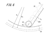
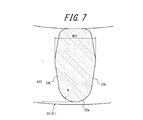
- the pin member 22 is not limited to a perfect circular cross-sectional shape as shown in FIG. 3B or the like.
- a tapered cross-sectional shape formed with a radius R22.
- the pin member 22 in FIG. 7 has a maximum width w22, and both ends of the maximum width w22 are connected to the tip 22a at a position of a length h22 via a plane 22b.
- the drive protrusion 14 adapted to the pin member 22 has a trapezoidal cross section in which the apex 14c of the elastic protrusion 14 is formed as a flat surface in a side view as shown in FIG.
- L 2 when the rotation direction of the sprocket 20 is only one direction, L 2 can be the front side in the rotation direction and L 1 can be the rear side in the rotation direction.
- the steel cord layer 12 is built in the endless belt-like portion 11 of the elastic crawler 10, but the main cord layer 12 can be omitted.
- various configurations, arrangements, and the like adopted in each embodiment can be used by appropriately combining and replacing each other.
- the present invention relates to an elastic crawler having a plurality of engaging portions that can be engaged with each of a plurality of pin members arranged at intervals in the circumferential direction of the sprocket, the elastic crawler,
- the present invention can be applied to an elastic crawler driving mechanism having a sprocket in which pin members are arranged at intervals in the circumferential direction.
Landscapes
- Engineering & Computer Science (AREA)
- Chemical & Material Sciences (AREA)
- Combustion & Propulsion (AREA)
- Transportation (AREA)
- Mechanical Engineering (AREA)
- Gears, Cams (AREA)
Abstract
Description
記
D1 =D0 ×a ・・・(1)
ここで、D0 =(前記係合部のピッチ)×(ピン部材の個数)/(円周率)、かつ、
0.9≦a<1
本発明に係る、弾性クローラによれば、ピン部材と係合部との干渉を抑制しつつ係合部の耐久性を向上させることができる。
この場合、ピン部材と係合部との干渉をより確実に抑制することができる。
記
D2 =D0 ×b ・・・(2)
ここで、1≦b≦1.1
この場合、ピン部材と係合部との干渉を抑制しつつ係合部の耐久性をより向上させることができる。
この場合、制動時や下り坂走行時における、ピン部材と係合部との干渉を抑制しつつ、当該係合部の体積を大きく保つことができる。
この場合、前記受圧面および前記逃げ面を前記接続部分で滑らかにつなぐことで、ピン部材および係合部の係合動作および解除動作をスムースに行うことができる。
この場合、ピン部材と係合部との干渉をより確実に抑制しつつ係合部の耐久性を向上させることができる。
記
D1 =D0 ×a ・・・(1)
ここで、D0 =(弾性突起14のピッチP)×(ピン部材22の個数)/(円周率π)、かつ、
0.9≦a<1
記
D2 =D0 ×b ・・・(2)
ここで、D0 =(弾性突起14のピッチP)×(ピン部材22の個数)/(円周率π)、かつ、
1≦b≦1.1
Claims (7)
- スプロケットの周方向に間隔を置いて配置された複数のピン部材のそれぞれに係合可能な複数の係合部を、内周側に有する弾性クローラであって、
前記係合部は、当該係合部の根元側に、前記ピン部材を受ける受圧面を有し、当該受圧面は、側面視の輪郭形状が、以下の式(1)で規定される転がり直径D1 の仮想回転体の中心軸と同軸で前記スプロケットが前記仮想回転体とともに平面上を転がったときに前記ピン部材の外縁が描く包絡線で形作られていることを特徴とする、弾性クローラ。
記
D1 =D0 ×a ・・・(1)
ここで、D0 =(前記係合部のピッチ)×(ピン部材の個数)/(円周率)、かつ、
0.9≦a<1 - 請求項1において、式(1)において、0.94≦a≦0.98の条件を満たす、弾性クローラ。
- 請求項1又は2において、前記係合部は、当該係合部の先端側に、前記ピン部材との干渉を回避するための逃げ面を有し、当該逃げ面は、側面視の輪郭形状が、以下の式(2)で規定される転がり直径D2 の仮想回転体の中心軸と同軸で前記スプロケットが前記仮想回転体とともに平面上を転がったときに前記ピン部材の外縁が描く包絡線で形作られている、弾性クローラ。
記
D2 =D0 ×b ・・・(2)
ここで、1≦b≦1.1 - 請求項3において、式(2)において、1.00≦b≦1.03の条件を満たす、弾性クローラ。
- 請求項3又は4において、前記受圧面および前記逃げ面の接続部分は、側面視の輪郭形状が、曲線で形作られている、弾性クローラ。
- 請求項1乃至5のいずれか1項において、前記受圧面および前記逃げ面の接続部分は、前記無端帯状体の内周面からの高さが前記係合部の全体高さの25%以上60%以下である、弾性クローラ。
- 請求項1乃至6のいずれか1項に記載の弾性クローラと、複数のピン部材が周方向に間隔を置いて配置されたスプロケットとを有する、弾性クローラ駆動機構。
Priority Applications (3)
| Application Number | Priority Date | Filing Date | Title |
|---|---|---|---|
| CA2980850A CA2980850C (en) | 2015-04-16 | 2016-04-12 | Elastic crawler and elastic crawler drive mechanism |
| US15/564,024 US10633043B2 (en) | 2015-04-16 | 2016-04-12 | Elastic crawler and elastic crawler drive mechanism |
| CN201680021473.7A CN107428384B (zh) | 2015-04-16 | 2016-04-12 | 弹性履带和弹性履带驱动机构 |
Applications Claiming Priority (2)
| Application Number | Priority Date | Filing Date | Title |
|---|---|---|---|
| JP2015083999A JP6473373B2 (ja) | 2015-04-16 | 2015-04-16 | 弾性クローラおよび弾性クローラ駆動機構 |
| JP2015-083999 | 2015-04-16 |
Publications (1)
| Publication Number | Publication Date |
|---|---|
| WO2016166969A1 true WO2016166969A1 (ja) | 2016-10-20 |
Family
ID=57125850
Family Applications (1)
| Application Number | Title | Priority Date | Filing Date |
|---|---|---|---|
| PCT/JP2016/001989 Ceased WO2016166969A1 (ja) | 2015-04-16 | 2016-04-12 | 弾性クローラおよび弾性クローラ駆動機構 |
Country Status (5)
| Country | Link |
|---|---|
| US (1) | US10633043B2 (ja) |
| JP (1) | JP6473373B2 (ja) |
| CN (1) | CN107428384B (ja) |
| CA (1) | CA2980850C (ja) |
| WO (1) | WO2016166969A1 (ja) |
Families Citing this family (1)
| Publication number | Priority date | Publication date | Assignee | Title |
|---|---|---|---|---|
| CN112389554A (zh) * | 2020-12-04 | 2021-02-23 | 徐州博汇世通重工机械有限责任公司 | 一种接地比压可调的履带驱动轮 |
Citations (3)
| Publication number | Priority date | Publication date | Assignee | Title |
|---|---|---|---|---|
| JPH0966869A (ja) * | 1995-08-31 | 1997-03-11 | Bridgestone Corp | 確実駆動ゴム軌道 |
| JPH09193852A (ja) * | 1996-01-16 | 1997-07-29 | Bridgestone Corp | 突起駆動型ゴムクロ−ラ |
| JP2007276735A (ja) * | 2006-04-11 | 2007-10-25 | Bridgestone Corp | 芯金レスクローラ |
Family Cites Families (6)
| Publication number | Priority date | Publication date | Assignee | Title |
|---|---|---|---|---|
| US7156474B2 (en) * | 2002-06-28 | 2007-01-02 | A.S.V., Inc. | Track and drive mechanism for a vehicle |
| JP2006069293A (ja) | 2004-08-31 | 2006-03-16 | Bridgestone Corp | 芯金レスゴムクロ−ラのスプロケット構造 |
| JP2006321387A (ja) * | 2005-05-19 | 2006-11-30 | Bridgestone Corp | 芯金レスクロ−ラの走行装置 |
| WO2006123779A1 (ja) | 2005-05-19 | 2006-11-23 | Bridgestone Corporation | 芯金レスクローラ |
| US8070240B2 (en) | 2008-12-18 | 2011-12-06 | Caterpillar Inc. | Sprocketed drive assembly for track-type machine |
| JP2014015156A (ja) | 2012-07-10 | 2014-01-30 | Bridgestone Corp | ゴムクローラ |
-
2015
- 2015-04-16 JP JP2015083999A patent/JP6473373B2/ja not_active Expired - Fee Related
-
2016
- 2016-04-12 WO PCT/JP2016/001989 patent/WO2016166969A1/ja not_active Ceased
- 2016-04-12 US US15/564,024 patent/US10633043B2/en active Active
- 2016-04-12 CN CN201680021473.7A patent/CN107428384B/zh not_active Expired - Fee Related
- 2016-04-12 CA CA2980850A patent/CA2980850C/en active Active
Patent Citations (3)
| Publication number | Priority date | Publication date | Assignee | Title |
|---|---|---|---|---|
| JPH0966869A (ja) * | 1995-08-31 | 1997-03-11 | Bridgestone Corp | 確実駆動ゴム軌道 |
| JPH09193852A (ja) * | 1996-01-16 | 1997-07-29 | Bridgestone Corp | 突起駆動型ゴムクロ−ラ |
| JP2007276735A (ja) * | 2006-04-11 | 2007-10-25 | Bridgestone Corp | 芯金レスクローラ |
Also Published As
| Publication number | Publication date |
|---|---|
| US10633043B2 (en) | 2020-04-28 |
| JP2016203678A (ja) | 2016-12-08 |
| CA2980850A1 (en) | 2016-10-20 |
| US20180134333A1 (en) | 2018-05-17 |
| CN107428384A (zh) | 2017-12-01 |
| JP6473373B2 (ja) | 2019-02-20 |
| CN107428384B (zh) | 2019-06-18 |
| CA2980850C (en) | 2019-07-09 |
Similar Documents
| Publication | Publication Date | Title |
|---|---|---|
| JP5189505B2 (ja) | ゴムクローラ | |
| JP2009061829A (ja) | ゴムクローラおよびそのゴムクローラ用芯金 | |
| US9932077B2 (en) | Crawler | |
| JP5373311B2 (ja) | ゴムクローラ | |
| CN102686475A (zh) | 链轮和具有该链轮的橡胶履带组装体 | |
| JP6473373B2 (ja) | 弾性クローラおよび弾性クローラ駆動機構 | |
| JP6993864B2 (ja) | 空気入りタイヤ | |
| JP6142798B2 (ja) | 空気入りタイヤ | |
| CA2988087A1 (en) | Crawler | |
| US20170327163A1 (en) | Elastic crawler drive mechanism | |
| JP6816593B2 (ja) | ベルトドラム装置 | |
| JP5818650B2 (ja) | 弾性クローラ | |
| JP2010274799A (ja) | 空気入りタイヤ | |
| JP2009208595A (ja) | 空気入りラジアルタイヤ | |
| JP2021088279A (ja) | 空気入りタイヤ | |
| JP4921793B2 (ja) | タイヤ用生ゴム部材の製造方法、及び空気入りタイヤ | |
| CN107614361B (zh) | 履带 | |
| CN116096588B (zh) | 轮胎 | |
| JP2013107471A (ja) | 弾性クローラ | |
| JP2012237333A (ja) | ブーツバンド | |
| JP6958299B2 (ja) | ゴムクローラ及びクローラ走行体 | |
| US9902445B2 (en) | Crawler | |
| JP2005324697A (ja) | 空気入りタイヤ用のビードコア | |
| JP5878314B2 (ja) | スプロケット、弾性クローラ組込体 | |
| JP7146630B2 (ja) | 空気入りタイヤ |
Legal Events
| Date | Code | Title | Description |
|---|---|---|---|
| 121 | Ep: the epo has been informed by wipo that ep was designated in this application |
Ref document number: 16779765 Country of ref document: EP Kind code of ref document: A1 |
|
| ENP | Entry into the national phase |
Ref document number: 2980850 Country of ref document: CA |
|
| WWE | Wipo information: entry into national phase |
Ref document number: 15564024 Country of ref document: US |
|
| NENP | Non-entry into the national phase |
Ref country code: DE |
|
| 122 | Ep: pct application non-entry in european phase |
Ref document number: 16779765 Country of ref document: EP Kind code of ref document: A1 |