WO2016166928A1 - 研磨ヘッドの製造方法及び研磨ヘッド、並びに研磨装置 - Google Patents
研磨ヘッドの製造方法及び研磨ヘッド、並びに研磨装置 Download PDFInfo
- Publication number
- WO2016166928A1 WO2016166928A1 PCT/JP2016/001148 JP2016001148W WO2016166928A1 WO 2016166928 A1 WO2016166928 A1 WO 2016166928A1 JP 2016001148 W JP2016001148 W JP 2016001148W WO 2016166928 A1 WO2016166928 A1 WO 2016166928A1
- Authority
- WO
- WIPO (PCT)
- Prior art keywords
- space
- incompressible fluid
- intermediate plate
- polishing head
- end surface
- Prior art date
- Legal status (The legal status is an assumption and is not a legal conclusion. Google has not performed a legal analysis and makes no representation as to the accuracy of the status listed.)
- Ceased
Links
Images




Classifications
-
- B—PERFORMING OPERATIONS; TRANSPORTING
- B24—GRINDING; POLISHING
- B24B—MACHINES, DEVICES, OR PROCESSES FOR GRINDING OR POLISHING; DRESSING OR CONDITIONING OF ABRADING SURFACES; FEEDING OF GRINDING, POLISHING, OR LAPPING AGENTS
- B24B37/00—Lapping machines or devices; Accessories
- B24B37/11—Lapping tools
- B24B37/20—Lapping pads for working plane surfaces
- B24B37/26—Lapping pads for working plane surfaces characterised by the shape of the lapping pad surface, e.g. grooved
-
- B—PERFORMING OPERATIONS; TRANSPORTING
- B24—GRINDING; POLISHING
- B24B—MACHINES, DEVICES, OR PROCESSES FOR GRINDING OR POLISHING; DRESSING OR CONDITIONING OF ABRADING SURFACES; FEEDING OF GRINDING, POLISHING, OR LAPPING AGENTS
- B24B37/00—Lapping machines or devices; Accessories
- B24B37/11—Lapping tools
- B24B37/20—Lapping pads for working plane surfaces
- B24B37/24—Lapping pads for working plane surfaces characterised by the composition or properties of the pad materials
-
- B—PERFORMING OPERATIONS; TRANSPORTING
- B24—GRINDING; POLISHING
- B24B—MACHINES, DEVICES, OR PROCESSES FOR GRINDING OR POLISHING; DRESSING OR CONDITIONING OF ABRADING SURFACES; FEEDING OF GRINDING, POLISHING, OR LAPPING AGENTS
- B24B37/00—Lapping machines or devices; Accessories
- B24B37/27—Work carriers
- B24B37/30—Work carriers for single side lapping of plane surfaces
-
- B—PERFORMING OPERATIONS; TRANSPORTING
- B24—GRINDING; POLISHING
- B24B—MACHINES, DEVICES, OR PROCESSES FOR GRINDING OR POLISHING; DRESSING OR CONDITIONING OF ABRADING SURFACES; FEEDING OF GRINDING, POLISHING, OR LAPPING AGENTS
- B24B41/00—Component parts such as frames, beds, carriages, headstocks
- B24B41/06—Work supports, e.g. adjustable steadies
-
- B—PERFORMING OPERATIONS; TRANSPORTING
- B24—GRINDING; POLISHING
- B24D—TOOLS FOR GRINDING, BUFFING OR SHARPENING
- B24D18/00—Manufacture of grinding tools or other grinding devices, e.g. wheels, not otherwise provided for
- B24D18/0027—Manufacture of grinding tools or other grinding devices, e.g. wheels, not otherwise provided for by impregnation
-
- B—PERFORMING OPERATIONS; TRANSPORTING
- B24—GRINDING; POLISHING
- B24D—TOOLS FOR GRINDING, BUFFING OR SHARPENING
- B24D18/00—Manufacture of grinding tools or other grinding devices, e.g. wheels, not otherwise provided for
- B24D18/0045—Manufacture of grinding tools or other grinding devices, e.g. wheels, not otherwise provided for by stacking sheets of abrasive material
-
- H—ELECTRICITY
- H10—SEMICONDUCTOR DEVICES; ELECTRIC SOLID-STATE DEVICES NOT OTHERWISE PROVIDED FOR
- H10P—GENERIC PROCESSES OR APPARATUS FOR THE MANUFACTURE OR TREATMENT OF DEVICES COVERED BY CLASS H10
- H10P52/00—Grinding, lapping or polishing of wafers, substrates or parts of devices
-
- B—PERFORMING OPERATIONS; TRANSPORTING
- B24—GRINDING; POLISHING
- B24B—MACHINES, DEVICES, OR PROCESSES FOR GRINDING OR POLISHING; DRESSING OR CONDITIONING OF ABRADING SURFACES; FEEDING OF GRINDING, POLISHING, OR LAPPING AGENTS
- B24B37/00—Lapping machines or devices; Accessories
- B24B37/04—Lapping machines or devices; Accessories designed for working plane surfaces
Definitions
- the present invention relates to a method for manufacturing a polishing head, a polishing head, and a polishing apparatus including the polishing head.
- the polishing is performed by pressing the wafer with the rubber film surface in close contact with the entire back surface of the wafer. Can do. Thereby, the polishing allowance of the wafer can be made uniform over the entire polishing surface, and a wafer with high flatness can be produced. Further, since the shape of the surface of the rubber film that adsorbs the wafer by the incompressible fluid can be controlled to be constant, a wafer with high reproducibility and high flatness can be obtained.
- parts of the polishing head may be submerged in an incompressible fluid, and the polishing head may be assembled by a human hand in the incompressible fluid.
- it is difficult to control the amount of incompressible fluid enclosed.
- the polishing head is assembled in an incompressible fluid, workability is significantly deteriorated.
- a polishing head used for polishing a large diameter wafer having a diameter of 300 mm or more has a large size and a very large weight, which causes a problem in safety as well as workability.
- the incompressible fluid to be sealed is harmful to the human body, the operation itself becomes impossible.
- the rigid ring 102, the intermediate plate 104, and the rubber film 103 are assembled to form a space portion 105 that encloses an incompressible fluid in the polishing head. Further, the intermediate plate 104 is formed with an inlet 107 for injecting an incompressible fluid and an outlet 108 for discharging air. Next, the inside of the space part 105 is decompressed.
- an incompressible fluid is poured into the space portion 105 from the inlet 107 communicating with the space portion 105, and at the same time, air remaining in the space portion 105 is discharged from the discharge port 108.
- this method is also referred to as a reduced pressure sealing method.
- workability can be greatly improved by assembling the polishing head in the atmosphere.
- the polishing head is inclined and placed so that the discharge port 108 is higher than the injection port 107, and the incompressible fluid 106 is placed in the space portion 105. Can be injected (upper left of FIG. 7). In this way, since the incompressible fluid 106 first starts to accumulate in the direction opposite to the discharge port 108 (upper right portion in FIG. 7), the discharge port 108 is blocked by the injected incompressible fluid 106. Time can be further increased, and the amount of air that can be discharged can be increased (lower left part of FIG. 7).
- the volume of the incompressible fluid to be sealed varies depending on the amount of remaining air.
- the present invention has been made in view of the above-mentioned problems.
- the workability is good and the amount of the incompressible fluid can be easily controlled.
- it aims at providing the manufacturing method of the polishing head which can reduce the quantity of the air which remains in a space part.
- the present invention also provides a polishing head that can reduce the amount of air remaining in a space filled with an incompressible fluid and can manufacture a wafer with high flatness with good reproducibility, and a polishing apparatus including the polishing head.
- the purpose is to do.
- the present invention provides an annular rigid ring, an elastic membrane attached to the lower end surface of the rigid ring with a uniform tension, and a disk-like shape coupled to the upper end surface of the rigid ring.
- An intermediate plate a space defined by a lower end surface of the intermediate plate, an upper surface of the elastic film, and an inner peripheral surface of the rigid ring, and an incompressible fluid sealed in the space,
- a method of manufacturing a polishing head for polishing a surface of a wafer by sliding the surface of the wafer against a polishing cloth affixed on a surface plate while holding the back surface of the wafer on the lower surface of an elastic film, Before being joined to the upper end surface of the rigid ring, an air inlet for injecting the incompressible fluid into the space and an air exhaust from the space when the incompressible fluid is injected into the intermediate plate.
- a method of manufacturing a polishing head comprising the step of enclosing in the space.
- the incompressible fluid is injected when the incompressible fluid is injected.
- the flow can be controlled appropriately. That is, the air remaining in the space can be discharged before the incompressible fluid closes the discharge port. Also, with such a manufacturing method, workability is good and the control of the injection amount of the incompressible fluid becomes easy.
- the incompressible fluid is placed while the middle plate is inclined and placed so that the injection port is positioned below the discharge port. It is preferable to inject into the space.
- the intermediate plate having a convex shape at the lower end surface forming the groove.
- the present invention provides an annular rigid ring, an elastic film attached to the lower end surface of the rigid ring with a uniform tension, and a disk coupled to the upper end surface of the rigid ring.
- An intermediate plate a space defined by a lower end surface of the intermediate plate, an upper surface of the elastic film, and an inner peripheral surface of the rigid ring, and an incompressible fluid sealed in the space.
- a polishing head that polishes the surface of the wafer by sliding against a polishing cloth affixed on a surface plate while holding the back surface of the wafer on the lower surface of the elastic film, On the end face, an inlet for injecting an incompressible fluid into the space, an outlet for discharging air from the space, a groove extending from the inlet to the outer periphery of the intermediate plate, A groove extending from the discharge port to the outer periphery of the intermediate plate, and the injection port and Providing a polishing head, wherein those having a lid portion for closing the outlet.
- Such a polishing head has a small amount of air remaining in the space filled with an incompressible fluid, and it is easy to control the shape of the surface that holds the elastic film wafer. Can be manufactured well.
- the present invention comprises an abrasive cloth affixed on a surface plate, an abrasive supply mechanism for supplying an abrasive onto the abrasive cloth, and the above polishing head.
- a polishing apparatus is characterized in that the workpiece is held by the polishing head and the surface of the workpiece is polished by being brought into sliding contact with a polishing cloth affixed on the surface plate.
- a polishing apparatus equipped with a polishing head as described above can produce a highly flat wafer with good reproducibility.
- the method for manufacturing a polishing head of the present invention can greatly reduce the amount of air remaining in the space when the incompressible fluid is sealed.
- this manufacturing method has good workability, and the amount of incompressible fluid enclosed can be easily controlled.
- the polishing head of the present invention has high flatness because the amount of air remaining in the space filled with the incompressible fluid is small and the shape of the surface holding the elastic film wafer can be easily controlled. Wafers can be manufactured with good reproducibility. The same effect can be obtained by a polishing apparatus equipped with the polishing head of the present invention.
- the reduced pressure encapsulation method has good workability and easy control of the amount of incompressible fluid enclosed.
- the incompressible fluid injected at an early stage before discharging a sufficient amount of air will block the outlet, so that the inlet and the outlet are short-circuited via the incompressible fluid.
- the inventors have formed a groove on the surface of the intermediate plate that defines the space portion, thereby allowing the flow of the incompressible fluid in the space portion. It has been found that the amount of residual air can be reduced by controlling the outer peripheral portion to flow first, and the present invention has been completed.
- the polishing head of the present invention will be described with reference to FIG.
- the polishing head 1 of the present invention is coupled to an annular rigid ring 2, an elastic film 3 attached to the lower end surface of the rigid ring 2 with a uniform tension, and an upper end surface of the rigid ring 2.
- a disc-shaped intermediate plate 4 a space portion 5 defined by the lower end surface of the intermediate plate 4, the upper surface of the elastic film 3, and the inner peripheral surface of the rigid ring 2, and the incompressibility enclosed in the space portion 5 Fluid 6.
- the intermediate plate 4 is formed with an inlet 7 and an outlet 8 that are used when the incompressible fluid 6 is sealed in the space 5 when the polishing head 1 is manufactured.
- the cover part 9 which closes the injection port 7 and the discharge port 8.
- FIG. 1 a one-touch joint 9 that can open and close the inlet 7 and the outlet 8 and has good workability as shown in FIG. 1 can be used.
- a groove 10 a extending from the inlet 7 to the outer peripheral portion 4 b of the intermediate plate 4 and an outlet 8 are provided on the lower end surface 4 a of the intermediate plate 4, that is, on the surface defining the space portion 5.
- a groove 10b extending to the outer peripheral portion 4b of the intermediate plate 4 is formed on the lower end surface 4 a of the intermediate plate 4, that is, on the surface defining the space portion 5.
- the outer peripheral portion of the intermediate plate referred to in the present invention is a portion located above the outer peripheral portion of the space portion, and the grooves 10a and 10b can extend at least to the lower end surface 4a of the intermediate plate 4 above the outer peripheral portion of the space portion 5. . Or you may extend
- Such a polishing head 1 can perform polishing by sliding the surface of the wafer against a polishing cloth affixed on a surface plate while holding the back surface of the wafer on the lower surface of the elastic film 3.
- the polishing head 1 may be one in which a backing pad is attached to the lower surface portion of the elastic film 3, and the elastic film 3 may hold the wafer via this backing pad.
- the backing pad is one that, for example, contains water and attaches the wafer, and holds the wafer on the wafer holding surface of the elastic film 3.
- the polishing head 1 may include an annular template for holding the edge portion of the wafer on the lower surface of the backing pad.
- Such a polishing head 1 has a very small amount of air remaining in the space 5, it is easy to control the shape of the surface holding the elastic film wafer during polishing of the wafer. As a result, a polishing head capable of manufacturing a highly flat wafer with good reproducibility is obtained.
- the polishing head manufacturing method of the present invention includes at least a step of forming an injection port and a discharge port in the intermediate plate (S101 in FIG. 3), and a step of forming a groove in the lower end surface of the intermediate plate ( 3 (S102), a step of forming the space portion by combining the intermediate plate, the rigid ring, and the elastic film (S103 of FIG. 3), a step of decompressing the space portion (S104 of FIG. 3), and an incompressible fluid in the space portion. Is included (S105 in FIG. 3).
- grooves 10a and 10b as shown in FIG. 2 are formed in the lower end surface 4a of the intermediate plate 4 (S102 in FIG. 3). Specifically, a groove 10a connecting an arbitrary point between the inlet 7 and the outer peripheral portion 4b is cut. Similarly, a groove 10b connecting an arbitrary point between the discharge port 8 and the outer peripheral portion 4b is cut.
- FIG. 2 shows an example in which the grooves 10a and 10b are formed so as to extend from the inlet 7 and the outlet 8 to the nearest outer peripheral portion.
- the cross-sectional shape of the groove cut in the intermediate plate can be, for example, a square having a width of 1 to 5 mm and a depth of 3 to 6 mm, but is not limited thereto.
- the shape of the groove may be any shape as long as it does not inhibit the flow of air and incompressible fluid and does not affect the strength of the intermediate plate.
- the elastic film 3 is attached to the lower end surface of the rigid ring 2, as shown in FIG.
- the space 5 is formed by joining the upper end surface of the rigid ring 2 and the lower end surface 4a in which the groove of the intermediate plate 4 is formed (103 in FIG. 3).
- the space 5 may be formed by assembling the rigid ring and rubber membrane assembly and the intermediate plate.
- the material of the rigid ring is preferably ceramic in order to prevent dissolution of metal impurities during wafer polishing.
- the inside of the space 5 is decompressed (S104 in FIG. 3).
- the interior of the space portion 5 can be decompressed by connecting the discharge port 8 and a vacuum generator such as an ejector (not shown) and operating the vacuum generator.
- the supply pressure of the ejector is preferably about 3 MPa.
- the inside of the space 5 can be sufficiently decompressed. Thereby, at least the center part of the lower end surface 4a of the intermediate plate 4 and the elastic film 3 are in close contact.
- the incompressible fluid 6 is injected from the injection port 7 with the discharge port 8 being opened.
- the incompressible fluid 6 it is preferable to use water from the viewpoint of safety and convenience.
- the inflow rate is preferably about 700 ml / min to 900 ml / min.
- the incompressible fluid 6 when the incompressible fluid 6 is injected into the space portion 5 in a state where the central portion of the lower end surface 4 a of the intermediate plate 4 and the elastic film 3 are in close contact with each other, the incompressible fluid 6 remains in the space portion 5.
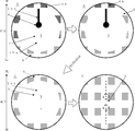
- the interior moves as shown in FIG. First, the incompressible fluid 6 is injected into the space portion 5 from the injection port 7. Subsequently, the incompressible fluid 6 extends from the inlet 7 toward the outer peripheral portion 4 b, that is, through the groove 10 a connecting the inlet 7 and the outer peripheral portion of the space portion 5. It flows below the portion 4b, in other words, to the outer peripheral portion of the space portion 5 (upper left portion in FIG. 4).
- the incompressible fluid 6 is placed in the space portion 5 in a state where the intermediate plate 4 coupled to the rigid ring is inclined and placed so that the inlet 7 is positioned below the outlet 8. It is preferable to inject into That is, it is preferable to place the intermediate plate 4 so that the height position of the groove 10 b connected to the discharge port 8 is lower than the height position of the groove 10 a connected to the injection port 7. Specifically, it is preferable to give the middle plate 4 an inclination of about 5 degrees from the horizontal plane. If the intermediate plate 4 is thus inclined and placed, the incompressible fluid 6 that has entered from the injection port 7 easily flows preferentially into the space of the outer peripheral portion 4b through the groove 10a.
- the incompressible fluid 6 flows along the outer peripheral portion 4b of the intermediate plate 4 and fills the outer peripheral portion of the space portion 5 (upper right portion in FIG. 4). At the same time, the air existing on the outer peripheral portion of the space portion 5 is discharged. Note that the incompressible fluid 6 does not flow because the central portion of the intermediate plate 4 is in a state where the intermediate plate 4 and the elastic film 3 are adsorbed by decompression.
- the middle plate 4 having a convex shape at the lower end surface 4a it is preferable to use the middle plate 4 having a convex shape at the lower end surface 4a. If the intermediate plate 4 having such a shape is used, the incompressible fluid 6 is more likely to flow along the outer peripheral portion 4 b of the intermediate plate 4. That is, it becomes easier to control the flow of the incompressible fluid 6 in the space 5.
- the incompressible fluid 6 reaches the discharge port 8 through the groove 10b (lower left portion in FIG. 4). Almost all of the air remaining on the outer periphery due to the movement of the incompressible fluid 6 so far is efficiently discharged. Whether or not the space of the outer peripheral portion 4b can be replaced with the incompressible fluid 6 can be determined when the replacement is completed when the incompressible fluid 6 starts to be discharged from the discharge portion 8 instead of air. After the discharge of air is completed, the discharge port 8 is closed while the injection of the incompressible fluid 6 is continued, so that water is also injected into the portion where the elastic film 3 and the middle plate 4 are adsorbed (see FIG. 4 on the lower right).
- the incompressible fluid 6 is injected until the desired amount is filled, and finally the inlet 7 is closed.
- the amount of the incompressible fluid to be enclosed can be calculated from the injection amount and the discharge amount, and can also be managed by measuring the weight of the polishing head before and after the encapsulation.
- the polishing head is manufactured by the procedure as described above, the amount of air remaining in the space 5 enclosing the incompressible fluid 6 can be greatly reduced. Therefore, it is easy to control the shape of the surface holding the elastic film wafer, and it is possible to reliably manufacture the polishing head of the present invention capable of manufacturing a highly flat wafer with good reproducibility.
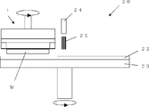
- the polishing head 1 of the present invention manufactured as described above can be used for holding the wafer W in the polishing apparatus 20 of the present invention as shown in FIG.
- the polishing apparatus 20 of the present invention includes an abrasive cloth 22 attached on a surface plate 23, an abrasive supply mechanism 24 for supplying an abrasive 25 onto the abrasive cloth 22,
- the polishing head 1 of the present invention described above is provided.
- the polishing head 1 has a structure in which a workpiece W can be pressed against a polishing cloth 22 affixed to a surface plate 23 by a pressing mechanism (not shown).
- the polishing head was manufactured by the polishing head manufacturing method of the present invention.
- the intermediate plate 4 a disc-shaped intermediate plate having a convex shape at the lower end surface 4a, a material of SUS, and a diameter of 360 mm was used.
- the grooves 10a and 10b formed on the intermediate plate are both grooves having a rectangular cross section with a width of 3 mm and a depth of 4.5 mm.
- water was used as the incompressible fluid 6.
- the inflow rate of water into the space was 800 ml / min.
- Comparative Example 1 A polishing head was assembled in water, which is an incompressible fluid, to produce a polishing head in which water was sealed in the space.
- the polishing head produced in Comparative Example 1 has the same basic structure as the polishing head of Example 1, but does not have a groove, an inlet, an outlet, and a lid on the lower end surface of the intermediate plate. Met.
- Comparative Example 2 Basically except that water is sealed in the space by the conventional decompression sealing method without forming a groove extending from the inlet to the outer periphery of the intermediate plate and a groove extending from the discharge port to the outer peripheral portion of the intermediate plate.
- a polishing head was produced in the same manner as in Example 1.
- Example 1 and Comparative Example 2 using the vacuum encapsulation method can be operated in a state where the polishing head is assembled in the atmosphere, so the head is assembled in an incompressible fluid. Compared to the method, the work time is less.
- the working time of the example was 1/3 or less of that of Comparative Example 2.
- Comparative Example 1 of the underwater assembly method was evaluated as “good” because the remaining air was 0% in terms of area.
- Comparative Example 1 of the underwater assembly method was evaluated as “good” because the remaining air was 0% in terms of area.
- Comparative Example 2 since the remaining air was 20% in terms of area, it was evaluated as “bad”.
- the underwater assembly method of Comparative Example 1 was evaluated as “bad” because the amount of enclosed water could not be adjusted.
- the reduced pressure injection method as in the example was evaluated as “good” because the amount of water enclosed could be controlled by the amount of incompressible fluid supplied.
- the polishing head of Comparative Example 2 even if the amount of water sealed can be controlled, the desired amount of incompressible fluid cannot be sealed due to the influence of residual air, and the actual shape of the wafer holding portion of the polishing head is constant. do not become. Therefore, the evaluation was evaluated as “substantially bad”.
- the polishing head manufactured in Example and Comparative Example 1 was used as a polishing head of a single-side polishing apparatus as shown in FIG. 5, and a silicon single crystal wafer having a diameter of 300 mm was polished on one side.
- a non-woven fabric was used as the polishing cloth, and an alkaline polishing liquid containing colloidal silica as the abrasive as abrasive grains was used.
- the rotation speed of the surface plate was 30 rpm, and the rotation speed of the polishing head was 30 rpm.
- the pressing force of the polishing head against the wafer was 20 kPa.
- the silicon single crystal wafer was polished and its flatness was evaluated.
- the results are shown in Table 2.
- the perimeter allowance change here represents the difference in allowance at points moved 1 mm and 3 mm respectively from the outer periphery to the center, and the smaller this value, the more even the outer periphery is polished flatly. Yes.
- Comparative Example 2 since the remaining volume of air is large, the wafer could not be handled correctly when the same amount of sealing was used as in Example and Comparative Example 1, and therefore data on the amount of change in the outer circumference allowance could not be acquired.
- the present invention is not limited to the above embodiment.
- the above-described embodiment is an exemplification, and the present invention has any configuration that has substantially the same configuration as the technical idea described in the claims of the present invention and that exhibits the same effects. Are included in the technical scope.
Landscapes
- Engineering & Computer Science (AREA)
- Mechanical Engineering (AREA)
- Manufacturing & Machinery (AREA)
- Finish Polishing, Edge Sharpening, And Grinding By Specific Grinding Devices (AREA)
- Mechanical Treatment Of Semiconductor (AREA)
- Constituent Portions Of Griding Lathes, Driving, Sensing And Control (AREA)
Abstract
Description
図3に示したフローに従って、本発明の研磨ヘッドの製造方法により研磨ヘッドを製造した。この際、中板4として、下端面4aが凸形状、材質がSUS、直径が360mmの円板状の中板を使用した。中板に形成した溝10a、10bは、両方とも断面形状が幅3mm、深さ4.5mmの長方形となる溝とした。また、非圧縮性流体6として水を使用した。また、空間部への水の流入速度は800ml/minとした。
非圧縮性流体である水中で研磨ヘッドを組み立て、水を空間部に封入した研磨ヘッドを作製した。比較例1で作製した研磨ヘッドは、実施例1の研磨ヘッドと基本的な構造は同じであるが、中板の下端面の溝、注入口、排出口、及び蓋部は有していないものであった。
注入口から中板の外周部まで延伸する溝及び排出口から中板の外周部まで延伸する溝を形成することなく、従来の減圧封入法により空間部に水を封入したこと以外、基本的に実施例1と同様に研磨ヘッドを製造した。


Claims (5)
- 環状の剛性リングと、該剛性リングの下端面に均一の張力で貼り付けられた弾性膜と、前記剛性リングの上端面に結合された円盤状の中板と、該中板の下端面と前記弾性膜の上面と前記剛性リングの内周面とにより区画された空間部と、前記空間部に封入された非圧縮性流体とを具備し、前記弾性膜の下面部にウェーハの裏面を保持しながら、前記ウェーハの表面を定盤上に貼り付けられた研磨布に摺接させて研磨する研磨ヘッドを製造する方法であって、
前記中板を前記剛性リングの上端面に結合する前に、
前記中板に、前記非圧縮性流体を前記空間部に注入するための注入口、及び前記非圧縮性流体の注入時に前記空間部からエアーを排出するための排出口を形成する工程と、
前記中板の下端面に、前記注入口から前記中板の外周部まで延伸する溝及び前記排出口から前記中板の外周部まで延伸する溝をそれぞれ形成する工程とを有し、
前記剛性リングの下端面に前記弾性膜を貼り付け、かつ、前記剛性リングの上端面と前記中板の前記溝を形成した下端面とを結合することにより前記空間部を形成した後に、
前記空間部内を減圧する工程と、
該減圧工程後、前記注入口から前記空間部に前記非圧縮性流体を注入しながら、前記排出口から前記空間部内のエアーを排出し、前記注入口及び前記排出口を閉じることで前記非圧縮性流体を前記空間部に封入する工程とを
有することを特徴とする研磨ヘッドの製造方法。 - 前記非圧縮性流体を前記空間部に封入する工程において、前記注入口が前記排出口よりも下方に位置するように前記中板を傾けて載置しながら前記非圧縮性流体を前記空間部に注入することを特徴とする請求項1に記載の研磨ヘッドの製造方法。
- 前記中板として、前記溝を形成する前記下端面の形状が凸形状となっているものを用いることを特徴とする請求項1又は請求項2に記載の研磨ヘッドの製造方法。
- 環状の剛性リングと、該剛性リングの下端面に均一の張力で貼り付けられた弾性膜と、前記剛性リングの上端面に結合された円盤状の中板と、該中板の下端面と前記弾性膜の上面と前記剛性リングの内周面とにより区画された空間部と、前記空間部に封入された非圧縮性流体とを具備し、前記弾性膜の下面部にウェーハの裏面を保持しながら、前記ウェーハの表面を定盤上に貼り付けられた研磨布に摺接させて研磨する研磨ヘッドであって、
前記中板が、下端面に、前記空間部に前記非圧縮性流体を注入するための注入口と、前記空間部からエアーを排出するための排出口と、前記注入口から前記中板の外周部まで延伸した溝と、前記排出口から前記中板の外周部まで延伸した溝と、前記注入口及び前記排出口を閉じるための蓋部とを有するものであることを特徴とする研磨ヘッド。 - 定盤上に貼り付けられた研磨布と、該研磨布上に研磨剤を供給するための研磨剤供給機構と、請求項4に記載の研磨ヘッドを具備し、該研磨ヘッドでワークを保持して前記ワークの表面を、前記定盤上に貼り付けられた研磨布に摺接させて研磨するものであることを特徴とする研磨装置。
Priority Applications (5)
| Application Number | Priority Date | Filing Date | Title |
|---|---|---|---|
| CN201680014659.XA CN107427989B (zh) | 2015-04-16 | 2016-03-03 | 研磨头的制造方法、研磨头以及研磨装置 |
| US15/557,499 US10464189B2 (en) | 2015-04-16 | 2016-03-03 | Method for manufacturing polishing head, polishing head, and polishing apparatus |
| DE112016000979.8T DE112016000979T5 (de) | 2015-04-16 | 2016-03-03 | Verfahren zum Herstellen eines Polierkopfes, Polierkopf und Poliervorrichtung |
| KR1020177026194A KR102317974B1 (ko) | 2015-04-16 | 2016-03-03 | 연마헤드의 제조방법 및 연마헤드, 그리고 연마장치 |
| SG11201707416UA SG11201707416UA (en) | 2015-04-16 | 2016-03-03 | Method for manufacturing polishing head, polishing head, and polishing apparatus |
Applications Claiming Priority (2)
| Application Number | Priority Date | Filing Date | Title |
|---|---|---|---|
| JP2015084098A JP6283957B2 (ja) | 2015-04-16 | 2015-04-16 | 研磨ヘッドの製造方法及び研磨ヘッド、並びに研磨装置 |
| JP2015-084098 | 2015-04-16 |
Publications (1)
| Publication Number | Publication Date |
|---|---|
| WO2016166928A1 true WO2016166928A1 (ja) | 2016-10-20 |
Family
ID=57126490
Family Applications (1)
| Application Number | Title | Priority Date | Filing Date |
|---|---|---|---|
| PCT/JP2016/001148 Ceased WO2016166928A1 (ja) | 2015-04-16 | 2016-03-03 | 研磨ヘッドの製造方法及び研磨ヘッド、並びに研磨装置 |
Country Status (8)
| Country | Link |
|---|---|
| US (1) | US10464189B2 (ja) |
| JP (1) | JP6283957B2 (ja) |
| KR (1) | KR102317974B1 (ja) |
| CN (1) | CN107427989B (ja) |
| DE (1) | DE112016000979T5 (ja) |
| SG (1) | SG11201707416UA (ja) |
| TW (1) | TWI680827B (ja) |
| WO (1) | WO2016166928A1 (ja) |
Families Citing this family (3)
| Publication number | Priority date | Publication date | Assignee | Title |
|---|---|---|---|---|
| JP6891847B2 (ja) * | 2018-04-05 | 2021-06-18 | 信越半導体株式会社 | 研磨ヘッド及びウェーハの研磨方法 |
| TWI850338B (zh) * | 2019-02-28 | 2024-08-01 | 美商應用材料股份有限公司 | 拋光墊、化學機械拋光系統、及控制拋光墊的背襯層的剛度的方法 |
| CN113798989B (zh) * | 2021-08-23 | 2023-08-01 | 东莞奥嘉德精密金属科技有限公司 | 一种用于金属制品表面的双面抛光装置 |
Citations (3)
| Publication number | Priority date | Publication date | Assignee | Title |
|---|---|---|---|---|
| JPS6352967A (ja) * | 1986-08-19 | 1988-03-07 | Mitsubishi Metal Corp | 研磨装置 |
| WO2013001719A1 (ja) * | 2011-06-29 | 2013-01-03 | 信越半導体株式会社 | 研磨ヘッド及び研磨装置 |
| JP2013166200A (ja) * | 2012-02-15 | 2013-08-29 | Shin Etsu Handotai Co Ltd | 研磨ヘッド及び研磨装置 |
Family Cites Families (9)
| Publication number | Priority date | Publication date | Assignee | Title |
|---|---|---|---|---|
| KR910009320B1 (ko) * | 1986-08-19 | 1991-11-09 | 미쓰비시 마테리알 가부시기가이샤 | 연마장치 |
| EP1080842A4 (en) * | 1998-10-30 | 2003-08-13 | Shinetsu Handotai Kk | METHOD AND DEVICE FOR GRINDING A SEMICONDUCTOR DISC |
| US6769973B2 (en) * | 2001-05-31 | 2004-08-03 | Samsung Electronics Co., Ltd. | Polishing head of chemical mechanical polishing apparatus and polishing method using the same |
| US6705923B2 (en) * | 2002-04-25 | 2004-03-16 | Taiwan Semiconductor Manufacturing Co., Ltd | Chemical mechanical polisher equipped with chilled wafer holder and polishing pad and method of using |
| JP4374370B2 (ja) * | 2006-10-27 | 2009-12-02 | 信越半導体株式会社 | 研磨ヘッド及び研磨装置 |
| JP5042778B2 (ja) * | 2007-10-31 | 2012-10-03 | 信越半導体株式会社 | ワーク研磨用ヘッド及びこの研磨ヘッドを備えた研磨装置 |
| JP5392483B2 (ja) * | 2009-08-31 | 2014-01-22 | 不二越機械工業株式会社 | 研磨装置 |
| US8591286B2 (en) * | 2010-08-11 | 2013-11-26 | Applied Materials, Inc. | Apparatus and method for temperature control during polishing |
| CN203887682U (zh) * | 2014-06-19 | 2014-10-22 | 中芯国际集成电路制造(北京)有限公司 | 研磨头及研磨装置 |
-
2015
- 2015-04-16 JP JP2015084098A patent/JP6283957B2/ja active Active
-
2016
- 2016-03-03 DE DE112016000979.8T patent/DE112016000979T5/de active Pending
- 2016-03-03 KR KR1020177026194A patent/KR102317974B1/ko active Active
- 2016-03-03 SG SG11201707416UA patent/SG11201707416UA/en unknown
- 2016-03-03 CN CN201680014659.XA patent/CN107427989B/zh active Active
- 2016-03-03 WO PCT/JP2016/001148 patent/WO2016166928A1/ja not_active Ceased
- 2016-03-03 US US15/557,499 patent/US10464189B2/en active Active
- 2016-03-07 TW TW105106852A patent/TWI680827B/zh active
Patent Citations (3)
| Publication number | Priority date | Publication date | Assignee | Title |
|---|---|---|---|---|
| JPS6352967A (ja) * | 1986-08-19 | 1988-03-07 | Mitsubishi Metal Corp | 研磨装置 |
| WO2013001719A1 (ja) * | 2011-06-29 | 2013-01-03 | 信越半導体株式会社 | 研磨ヘッド及び研磨装置 |
| JP2013166200A (ja) * | 2012-02-15 | 2013-08-29 | Shin Etsu Handotai Co Ltd | 研磨ヘッド及び研磨装置 |
Also Published As
| Publication number | Publication date |
|---|---|
| CN107427989B (zh) | 2019-07-12 |
| US20180043500A1 (en) | 2018-02-15 |
| US10464189B2 (en) | 2019-11-05 |
| KR102317974B1 (ko) | 2021-10-28 |
| SG11201707416UA (en) | 2017-10-30 |
| DE112016000979T5 (de) | 2018-01-18 |
| KR20170138406A (ko) | 2017-12-15 |
| TW201637775A (zh) | 2016-11-01 |
| JP2016203270A (ja) | 2016-12-08 |
| JP6283957B2 (ja) | 2018-02-28 |
| CN107427989A (zh) | 2017-12-01 |
| TWI680827B (zh) | 2020-01-01 |
Similar Documents
| Publication | Publication Date | Title |
|---|---|---|
| JP3889744B2 (ja) | 研磨ヘッドおよび研磨装置 | |
| CN105358291B (zh) | 研磨头的制造方法及研磨装置 | |
| JP6283957B2 (ja) | 研磨ヘッドの製造方法及び研磨ヘッド、並びに研磨装置 | |
| TWI847229B (zh) | 拋光設備和拋光方法 | |
| TWI733705B (zh) | 化學機械拋光系統 | |
| CN101827684A (zh) | 研磨头、研磨装置以及工件的剥离方法 | |
| TWI847108B (zh) | 研磨頭、研磨處理方法及研磨處理裝置 | |
| JP3977037B2 (ja) | 四辺形基板の研磨装置 | |
| TWI826630B (zh) | 晶圓研磨用頭 | |
| JP5878733B2 (ja) | テンプレート押圧ウェハ研磨方式 | |
| JP5789870B2 (ja) | 防浸構造を備えた研磨パッド用補助板および研磨装置 | |
| JP4262226B2 (ja) | 研磨装置および研磨方法 | |
| JP4307674B2 (ja) | ウェーハの研磨装置 | |
| JP5077756B2 (ja) | 研磨装置 | |
| JP5238293B2 (ja) | 研磨ヘッド及び研磨装置並びに研磨方法 | |
| KR102057832B1 (ko) | 웨이퍼 연마용 헤드 | |
| JP2005335016A (ja) | 研磨布用ドレッシングプレート及び研磨布のドレッシング方法並びにワークの研磨方法 | |
| JP3638138B2 (ja) | ウエーハ保持盤の作製方法及びウエーハの研磨方法 | |
| JP2014200868A (ja) | 研磨装置 | |
| JP2001079757A (ja) | 研磨装置 | |
| JP2000326212A (ja) | 半導体基板の平坦化研磨装置および平坦化研磨方法 | |
| JP2017127938A (ja) | ウェーハの研磨方法、バックパッドの製造方法、バックパッド、及びそのバックパッドを具備する研磨ヘッド | |
| JP2011255464A (ja) | テンプレート押圧ウェハ研磨方式 | |
| JP2002231670A (ja) | ポリッシング装置 | |
| JP2005117070A (ja) | 半導体装置の製造方法 |
Legal Events
| Date | Code | Title | Description |
|---|---|---|---|
| 121 | Ep: the epo has been informed by wipo that ep was designated in this application |
Ref document number: 16779727 Country of ref document: EP Kind code of ref document: A1 |
|
| WWE | Wipo information: entry into national phase |
Ref document number: 11201707416U Country of ref document: SG Ref document number: 15557499 Country of ref document: US |
|
| ENP | Entry into the national phase |
Ref document number: 20177026194 Country of ref document: KR Kind code of ref document: A |
|
| WWE | Wipo information: entry into national phase |
Ref document number: 112016000979 Country of ref document: DE |
|
| 122 | Ep: pct application non-entry in european phase |
Ref document number: 16779727 Country of ref document: EP Kind code of ref document: A1 |