WO2016163176A1 - 照明装置および表示装置 - Google Patents
照明装置および表示装置 Download PDFInfo
- Publication number
- WO2016163176A1 WO2016163176A1 PCT/JP2016/056202 JP2016056202W WO2016163176A1 WO 2016163176 A1 WO2016163176 A1 WO 2016163176A1 JP 2016056202 W JP2016056202 W JP 2016056202W WO 2016163176 A1 WO2016163176 A1 WO 2016163176A1
- Authority
- WO
- WIPO (PCT)
- Prior art keywords
- light
- light guide
- substrate
- light source
- lighting device
- Prior art date
Links
Images


Classifications
-
- G—PHYSICS
- G02—OPTICS
- G02B—OPTICAL ELEMENTS, SYSTEMS OR APPARATUS
- G02B6/00—Light guides; Structural details of arrangements comprising light guides and other optical elements, e.g. couplings
- G02B6/0001—Light guides; Structural details of arrangements comprising light guides and other optical elements, e.g. couplings specially adapted for lighting devices or systems
- G02B6/0011—Light guides; Structural details of arrangements comprising light guides and other optical elements, e.g. couplings specially adapted for lighting devices or systems the light guides being planar or of plate-like form
-
- F—MECHANICAL ENGINEERING; LIGHTING; HEATING; WEAPONS; BLASTING
- F21—LIGHTING
- F21S—NON-PORTABLE LIGHTING DEVICES; SYSTEMS THEREOF; VEHICLE LIGHTING DEVICES SPECIALLY ADAPTED FOR VEHICLE EXTERIORS
- F21S2/00—Systems of lighting devices, not provided for in main groups F21S4/00 - F21S10/00 or F21S19/00, e.g. of modular construction
-
- F—MECHANICAL ENGINEERING; LIGHTING; HEATING; WEAPONS; BLASTING
- F21—LIGHTING
- F21V—FUNCTIONAL FEATURES OR DETAILS OF LIGHTING DEVICES OR SYSTEMS THEREOF; STRUCTURAL COMBINATIONS OF LIGHTING DEVICES WITH OTHER ARTICLES, NOT OTHERWISE PROVIDED FOR
- F21V19/00—Fastening of light sources or lamp holders
-
- F—MECHANICAL ENGINEERING; LIGHTING; HEATING; WEAPONS; BLASTING
- F21—LIGHTING
- F21V—FUNCTIONAL FEATURES OR DETAILS OF LIGHTING DEVICES OR SYSTEMS THEREOF; STRUCTURAL COMBINATIONS OF LIGHTING DEVICES WITH OTHER ARTICLES, NOT OTHERWISE PROVIDED FOR
- F21V23/00—Arrangement of electric circuit elements in or on lighting devices
- F21V23/003—Arrangement of electric circuit elements in or on lighting devices the elements being electronics drivers or controllers for operating the light source, e.g. for a LED array
- F21V23/004—Arrangement of electric circuit elements in or on lighting devices the elements being electronics drivers or controllers for operating the light source, e.g. for a LED array arranged on a substrate, e.g. a printed circuit board
-
- F—MECHANICAL ENGINEERING; LIGHTING; HEATING; WEAPONS; BLASTING
- F21—LIGHTING
- F21V—FUNCTIONAL FEATURES OR DETAILS OF LIGHTING DEVICES OR SYSTEMS THEREOF; STRUCTURAL COMBINATIONS OF LIGHTING DEVICES WITH OTHER ARTICLES, NOT OTHERWISE PROVIDED FOR
- F21V29/00—Protecting lighting devices from thermal damage; Cooling or heating arrangements specially adapted for lighting devices or systems
- F21V29/50—Cooling arrangements
- F21V29/502—Cooling arrangements characterised by the adaptation for cooling of specific components
- F21V29/503—Cooling arrangements characterised by the adaptation for cooling of specific components of light sources
-
- F—MECHANICAL ENGINEERING; LIGHTING; HEATING; WEAPONS; BLASTING
- F21—LIGHTING
- F21V—FUNCTIONAL FEATURES OR DETAILS OF LIGHTING DEVICES OR SYSTEMS THEREOF; STRUCTURAL COMBINATIONS OF LIGHTING DEVICES WITH OTHER ARTICLES, NOT OTHERWISE PROVIDED FOR
- F21V29/00—Protecting lighting devices from thermal damage; Cooling or heating arrangements specially adapted for lighting devices or systems
- F21V29/50—Cooling arrangements
- F21V29/502—Cooling arrangements characterised by the adaptation for cooling of specific components
- F21V29/508—Cooling arrangements characterised by the adaptation for cooling of specific components of electrical circuits
-
- F—MECHANICAL ENGINEERING; LIGHTING; HEATING; WEAPONS; BLASTING
- F21—LIGHTING
- F21V—FUNCTIONAL FEATURES OR DETAILS OF LIGHTING DEVICES OR SYSTEMS THEREOF; STRUCTURAL COMBINATIONS OF LIGHTING DEVICES WITH OTHER ARTICLES, NOT OTHERWISE PROVIDED FOR
- F21V29/00—Protecting lighting devices from thermal damage; Cooling or heating arrangements specially adapted for lighting devices or systems
- F21V29/50—Cooling arrangements
- F21V29/70—Cooling arrangements characterised by passive heat-dissipating elements, e.g. heat-sinks
-
- F—MECHANICAL ENGINEERING; LIGHTING; HEATING; WEAPONS; BLASTING
- F21—LIGHTING
- F21V—FUNCTIONAL FEATURES OR DETAILS OF LIGHTING DEVICES OR SYSTEMS THEREOF; STRUCTURAL COMBINATIONS OF LIGHTING DEVICES WITH OTHER ARTICLES, NOT OTHERWISE PROVIDED FOR
- F21V7/00—Reflectors for light sources
- F21V7/0008—Reflectors for light sources providing for indirect lighting
-
- G—PHYSICS
- G02—OPTICS
- G02B—OPTICAL ELEMENTS, SYSTEMS OR APPARATUS
- G02B6/00—Light guides; Structural details of arrangements comprising light guides and other optical elements, e.g. couplings
- G02B6/0001—Light guides; Structural details of arrangements comprising light guides and other optical elements, e.g. couplings specially adapted for lighting devices or systems
- G02B6/0011—Light guides; Structural details of arrangements comprising light guides and other optical elements, e.g. couplings specially adapted for lighting devices or systems the light guides being planar or of plate-like form
- G02B6/0066—Light guides; Structural details of arrangements comprising light guides and other optical elements, e.g. couplings specially adapted for lighting devices or systems the light guides being planar or of plate-like form characterised by the light source being coupled to the light guide
- G02B6/0068—Arrangements of plural sources, e.g. multi-colour light sources
-
- G—PHYSICS
- G02—OPTICS
- G02B—OPTICAL ELEMENTS, SYSTEMS OR APPARATUS
- G02B6/00—Light guides; Structural details of arrangements comprising light guides and other optical elements, e.g. couplings
- G02B6/0001—Light guides; Structural details of arrangements comprising light guides and other optical elements, e.g. couplings specially adapted for lighting devices or systems
- G02B6/0011—Light guides; Structural details of arrangements comprising light guides and other optical elements, e.g. couplings specially adapted for lighting devices or systems the light guides being planar or of plate-like form
- G02B6/0075—Arrangements of multiple light guides
- G02B6/0076—Stacked arrangements of multiple light guides of the same or different cross-sectional area
-
- G—PHYSICS
- G02—OPTICS
- G02B—OPTICAL ELEMENTS, SYSTEMS OR APPARATUS
- G02B6/00—Light guides; Structural details of arrangements comprising light guides and other optical elements, e.g. couplings
- G02B6/0001—Light guides; Structural details of arrangements comprising light guides and other optical elements, e.g. couplings specially adapted for lighting devices or systems
- G02B6/0011—Light guides; Structural details of arrangements comprising light guides and other optical elements, e.g. couplings specially adapted for lighting devices or systems the light guides being planar or of plate-like form
- G02B6/0081—Mechanical or electrical aspects of the light guide and light source in the lighting device peculiar to the adaptation to planar light guides, e.g. concerning packaging
- G02B6/0086—Positioning aspects
- G02B6/0091—Positioning aspects of the light source relative to the light guide
-
- F—MECHANICAL ENGINEERING; LIGHTING; HEATING; WEAPONS; BLASTING
- F21—LIGHTING
- F21V—FUNCTIONAL FEATURES OR DETAILS OF LIGHTING DEVICES OR SYSTEMS THEREOF; STRUCTURAL COMBINATIONS OF LIGHTING DEVICES WITH OTHER ARTICLES, NOT OTHERWISE PROVIDED FOR
- F21V2200/00—Use of light guides, e.g. fibre optic devices, in lighting devices or systems
- F21V2200/20—Use of light guides, e.g. fibre optic devices, in lighting devices or systems of light guides of a generally planar shape
-
- G—PHYSICS
- G02—OPTICS
- G02B—OPTICAL ELEMENTS, SYSTEMS OR APPARATUS
- G02B6/00—Light guides; Structural details of arrangements comprising light guides and other optical elements, e.g. couplings
- G02B6/0001—Light guides; Structural details of arrangements comprising light guides and other optical elements, e.g. couplings specially adapted for lighting devices or systems
- G02B6/0011—Light guides; Structural details of arrangements comprising light guides and other optical elements, e.g. couplings specially adapted for lighting devices or systems the light guides being planar or of plate-like form
- G02B6/0081—Mechanical or electrical aspects of the light guide and light source in the lighting device peculiar to the adaptation to planar light guides, e.g. concerning packaging
- G02B6/0083—Details of electrical connections of light sources to drivers, circuit boards, or the like
-
- G—PHYSICS
- G02—OPTICS
- G02B—OPTICAL ELEMENTS, SYSTEMS OR APPARATUS
- G02B6/00—Light guides; Structural details of arrangements comprising light guides and other optical elements, e.g. couplings
- G02B6/0001—Light guides; Structural details of arrangements comprising light guides and other optical elements, e.g. couplings specially adapted for lighting devices or systems
- G02B6/0011—Light guides; Structural details of arrangements comprising light guides and other optical elements, e.g. couplings specially adapted for lighting devices or systems the light guides being planar or of plate-like form
- G02B6/0081—Mechanical or electrical aspects of the light guide and light source in the lighting device peculiar to the adaptation to planar light guides, e.g. concerning packaging
- G02B6/0085—Means for removing heat created by the light source from the package
-
- G—PHYSICS
- G02—OPTICS
- G02B—OPTICAL ELEMENTS, SYSTEMS OR APPARATUS
- G02B6/00—Light guides; Structural details of arrangements comprising light guides and other optical elements, e.g. couplings
- G02B6/0001—Light guides; Structural details of arrangements comprising light guides and other optical elements, e.g. couplings specially adapted for lighting devices or systems
- G02B6/0011—Light guides; Structural details of arrangements comprising light guides and other optical elements, e.g. couplings specially adapted for lighting devices or systems the light guides being planar or of plate-like form
- G02B6/0081—Mechanical or electrical aspects of the light guide and light source in the lighting device peculiar to the adaptation to planar light guides, e.g. concerning packaging
- G02B6/0093—Means for protecting the light guide
Definitions
- the present disclosure relates to a lighting device using a light guide plate and a display device including such a lighting device.
- partial screen driving local dimming
- the direct type backlight can perform effective partial driving (subdivision of the light emitting region), but there is a problem that the thickness increases.
- an edge light type backlight for example, Patent Documents 1 and 2.
- the backlight can be thinned.
- effective partial driving is realized by using a plurality of light guide plates.
- An illumination device includes a light guide unit including a plurality of light guide plates each having a light incident part and a light emission surface and stacked in the thickness direction, and each of the light guide parts.
- a plurality of light sources that emit light toward the light incident portion of the light guide plate, and a substrate that supports the plurality of light sources and on which a circuit unit for driving each light source is disposed.
- positioned is arrange
- a display device includes the illumination device according to the embodiment of the present disclosure.
- a circuit unit for driving each light source is disposed on a substrate that supports a plurality of light sources, and the first portion on which the circuit unit of the substrate is disposed
- the light guide is disposed opposite the back surface.
- a circuit unit for driving each light source is disposed on a substrate that supports a plurality of light sources, and the first portion on which the circuit unit of the substrate is disposed
- the light guide is disposed opposite the back surface.
- FIG. 12 It is sectional drawing showing the structure of the display apparatus which concerns on one embodiment of this indication. It is a cross-sectional schematic diagram showing the structure of the light-guide plate shown in FIG. It is a schematic diagram for demonstrating the reflection pattern of the upper light-guide plate shown in FIG. It is a schematic diagram for demonstrating the reflective pattern of the lower side light-guide plate shown in FIG. It is a schematic diagram showing the structure of the cross section containing the light source of the structure shown in FIG. It is a schematic diagram showing the structure of the cross section which does not contain the light source of the structure shown in FIG. 12 is a schematic cross-sectional view for explaining the effect of the backlight unit according to Comparative Example 1.
- FIG. 1 It is a cross-sectional schematic diagram showing the structure of the light-guide plate shown in FIG. It is a schematic diagram for demonstrating the reflection pattern of the upper light-guide plate shown in FIG. It is a schematic diagram for demonstrating the reflective pattern of the lower side light-guide plate shown in FIG. It is a schematic diagram showing the
- FIG. 3A It is a schematic diagram showing an example of light source lighting of the light guide plate shown in FIG. 3A. It is a schematic diagram showing an example of the light source lighting of the light guide plate shown in FIG. 3B. It is a schematic diagram for demonstrating the partial drive using the two light-guide plates shown to FIG. 3A and FIG. 3B. It is a schematic diagram for demonstrating the effect of the backlight unit which concerns on the comparative example 4.
- FIG. 3A shows an example of light source lighting of the light guide plate shown in FIG. 3A.
- FIG. 3B It is a schematic diagram for demonstrating the partial drive using the two light-guide plates shown to FIG. 3A and FIG. 3B.
- FIG. 4 It is a cross-sectional schematic diagram for demonstrating the effect of the backlight unit which concerns on the comparative example 4.
- FIG. 12 is a characteristic diagram for explaining a light extraction pattern of a light guide plate according to Modification Example 1.
- FIG. 12 is a schematic diagram for explaining a light extraction pattern of a light guide plate according to Modification Example 1.
- FIG. 12 is a schematic diagram for explaining a light extraction pattern of a light guide plate according to Modification Example 1.
- FIG. 12 is a characteristic diagram for explaining a light extraction pattern of a light guide plate according to Modification Example 1.
- FIG. 12 is a characteristic diagram for explaining a light extraction pattern of a light guide plate according to Modification Example 1.
- FIG. 12 is a schematic diagram for explaining a light extraction pattern of a light guide plate according to Modification Example 1.
- FIG. 12 is a schematic diagram for explaining a light extraction pattern of a light guide plate according to Modification Example 1.
- FIG. 11 is a schematic cross-sectional view illustrating a main part configuration of a backlight unit according to Modification Example 2.
- FIG. 11 is a schematic cross-sectional view illustrating a main part configuration of a backlight unit according to Modification 3. It is a schematic diagram for demonstrating each light emission area
- FIG. 11 is a schematic cross-sectional view illustrating a main part configuration of a backlight unit according to Modification Example 4.
- FIG. 11 is a schematic cross-sectional view illustrating a main part configuration of a backlight unit according to Modification Example 4.
- FIG. 11 is a schematic cross-sectional view illustrating a main part configuration of a backlight unit according to Modification Example 4. It is the schematic diagram which looked at the light source shown in each of Drawing 21A and Drawing 21B from the front.
- FIG. 11 is a schematic cross-sectional view illustrating a main part configuration of a backlight unit according to Modification Example 5.
- FIG. 11 is a schematic cross-sectional view illustrating a main part configuration of a backlight unit according to Modification Example 6.
- FIG. 11 is a schematic cross-sectional view illustrating a main part configuration of a backlight unit according to Modification Example 7.
- FIG. 16 is a schematic cross-sectional view illustrating a main configuration of a backlight unit according to Modification Example 8.
- FIG. 11 is a schematic cross-sectional view illustrating a main configuration of a backlight unit according to Modification Example 4.
- FIG. 16 is a schematic cross-sectional view illustrating a main configuration of a backlight unit according to Modification 9.
- FIG. 16 is a schematic cross-sectional view illustrating a main part configuration of a backlight unit according to Modification Example 10.
- FIG. 16 is a schematic cross-sectional view illustrating a main part configuration of a backlight unit according to Modification Example 11.
- FIG. 16 is a schematic cross-sectional view illustrating a main part configuration of a backlight unit according to Modification 12. It is a schematic diagram for demonstrating the reflective pattern of the light-guide plate (upper side) which concerns on the modification 13. As shown in FIG. It is a schematic diagram for demonstrating the reflective pattern of the light-guide plate (lower side) which concerns on the modification 13. As shown in FIG.
- FIG. 31A It is a schematic diagram showing an example of the light source lighting of the light-guide plate shown to FIG. 31A. It is a schematic diagram showing an example of the light source lighting of the light-guide plate shown to FIG. 31B. It is a perspective view showing the external appearance of the illuminating device which concerns on another modification. It is a perspective view showing the external appearance of the illuminating device which concerns on another modification. It is a perspective view showing the external appearance of the illuminating device which concerns on another modification.
- Embodiment an example of a display device provided with a backlight unit in which a light source substrate is bent
- Modification 1 (Another example of the reflection pattern of the light guide plate) 3.
- Modification 2 (Another example of the bent shape of the substrate) 4).
- Modifications 3 to 5 (examples using an edge-emitting light source) 5.
- Modification 6 (Example in which a shape is given to the light incident portion of the light guide plate) 6).
- Modification 7 (example in which a top emission type light source and an edge emission type light source are used in combination) 7).
- Modifications 8 and 9 (example in which a functional sheet is disposed between light guide plates) 8).
- Modifications 10 and 11 (example in which a part of the light source substrate also serves as a light shielding member) 9.
- Modification 12 (example when the end of the substrate is bent in a Z shape) 10.
- Modification 13 (Other example of light source arrangement)
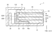
- FIG. 1 illustrates a cross-sectional configuration of a display device (display device 1) according to an embodiment of the present disclosure.
- the display device 1 is, for example, a liquid crystal display, and includes a backlight unit 10, a liquid crystal panel unit 20, a front case 30, and a back case 31. Note that the configuration shown in FIG. 1 corresponds to a part (end portion) of the display device 1. Note that the backlight unit 10 of the present embodiment corresponds to a specific example of “illumination device” in the present disclosure.
- the backlight unit 10 is a flat surface light source that illuminates the liquid crystal panel unit 20.
- the surface shape (XY planar shape) of the backlight unit 10 is, for example, a rectangular shape.
- driving partial driving or local dimming
- the light guide unit described later divides the XY plane into several regions and changes the emission intensity for each of the divided regions. A specific configuration of the backlight unit 10 will be described later.
- the liquid crystal panel unit 20 is for displaying an image such as a moving image or a still image.
- a substrate on which a pixel circuit such as a TFT (TFT substrate) is formed and a substrate on which a color filter is formed (CF A liquid crystal layer is sealed between the substrate and the substrate.
- a polarizing plate and various optical sheets (not shown) are bonded to the surfaces on the light incident side and the light emitting side of the liquid crystal panel unit 20, respectively.
- a protective cover film is attached to the surface of the liquid crystal panel unit 20.
- the planar shape (XY planar shape) of the liquid crystal panel unit 20 is, for example, a rectangular shape.
- the TFT substrate is provided with, for example, a pixel electrode, a TFT (ThinTFTFilm ⁇ ⁇ Transistor) element for driving each pixel, and wiring such as a gate line and a source line connected to the TFT element on a glass substrate.
- the CF substrate is, for example, a glass substrate provided with color filters such as red (R), green (G), and blue (B) and a counter electrode.
- the liquid crystal layer is composed of, for example, a liquid crystal driven in a VA mode, an IPS mode, a TN mode, or the like.
- the front-side housing 30 and the back-side housing 31 are members that support and house the liquid crystal panel unit 20 and the backlight unit 10.
- the front housing 30 is provided with an opening corresponding to the effective display area of the liquid crystal panel unit 20.
- the constituent material of the front side case 30 and the back side case 31 may be a metal such as aluminum (Al) and iron (Fe), or may be a resin such as polycarbonate (PC). Good.
- the backlight unit 10 includes, for example, a light guide unit 11 including a plurality (here, two) of light guide plates 11A and 11B, a light source (13A1 and 13B1) provided for each of the light guide plates 11A and 11B, and a light source substrate 12. And an optical sheet 14, a reflection sheet 15, a heat radiating member 16, a heat diffusion / heat insulating sheet 17, and a light shielding member 18.
- the light guide unit 11 is formed by stacking two light guide plates 11A and 11B along the thickness direction.
- FIG. 2 schematically shows the XZ cross-sectional configuration of each light extraction pattern (dot pattern) of the light guide plates 11A and 11B.
- 3A and 3B schematically represent the XY plane configuration of each pattern of the light guide plates 11A and 11B.
- the light guide plates 11A and 11B have light incident portions (S11 and S21) and light emission surfaces (S12 and S22).
- the light exit surface S12 is the light exit surface of the entire light guide unit 11.
- the light guide plate 11A is disposed to face the light output surface S22 of the light guide plate 11B, and the optical sheet 14 is bonded onto the light output surface S12 of the light guide plate 11A.
- the light guide plates 11A and 11B are arranged so as to overlap each other.
- Light extraction patterns are formed in selective areas different from each other between the light guide plates 11A and 11B.
- the light reflected in the region where such a pattern is formed is emitted (taken out) from the light emission surfaces S12 and S22.
- the XY plane shape of the light guide plates 11 ⁇ / b> A and 11 ⁇ / b> B has, for example, a rectangular shape as in the backlight unit 10.
- the end surfaces corresponding to the two rectangular short sides of the light guide plates 11A and 11B are the light incident portions S11 and S21.
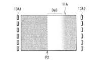
- the reflection surface S13 of the light guide plate 11A is divided into four regions Da1 to Da4 in the XY plane, and two of these regions Da1 and Da3 are compared to the other regions Da2 and Da4.
- a pattern from which more light can be extracted is formed.
- the pattern density (dot density) is higher than in the areas Da2 and Da4.
- the reflection surface S23 of the light guide plate 11B is divided into four regions Db1 to Db4 in the XY plane, and in these two regions Db2 and Db4, more than the other regions Db1 and Db3. A pattern from which much light can be extracted is formed.
- each of the light guide plates 11A and 11B is divided into several regions, and patterns are densely formed in selective regions that are different between the upper and lower light guide plates among the divided regions.
- a plurality of light sources are arranged opposite to the end surfaces (light incident portions S11 and S21) of these light guide plates 11A and 11B.
- the end surfaces extending along the Y direction of the light guide plates 11A and 11B are the light incident portions S11 and S21.
- the case where four light sources are arranged opposite to each other is illustrated, and the light sources arranged on the end surface of the light guide plate 11A on the X direction negative side (left side in the figure) are light sources 13A1 (13A11 to 13A14).
- the light source arranged on the end face on the X direction positive side (right side in the figure) is a light source 13A2 (13A21 to 13A24).
- the light source disposed on the X direction negative side end surface of the light guide plate 11B is the light source 13B1 (13B11 to 13B14), and the light source disposed on the X direction positive side end surface is the light source 13B2 (13B21 to 13B24).
- the light and dark (white to black display) of the area Da1 is set by driving the light sources 13A11 to 13A14, and the light and dark (white to black display) of the area Da3 drives the light sources 13A21 to 13A24.
- each of the light sources 13A11 to 13A14 and 13A21 to 13A24 is driven separately, so that the light emitting area is further divided into four in the areas Da1 and Da3.
- the light guide plate 11B for example, the light and dark (white to black display) of the region Db2 is set by driving the light sources 13B11 to 13B14, and the light and dark (white to black display) of the region Db4 is driven to the light sources 13B21 to 13B24.
- each of the light sources 13B11 to 13B14 and 13B21 to 13B24 is driven separately, so that the light emitting area is further divided into four in the regions Db2 and Db4.
- the light emitting region can be further finely divided (subdivided) in the Y direction.
- the light source 13A11 to 13A14 is irradiated by changing the pattern formation region and selectively forming the pattern in the regions Da1 and Da4 (no pattern is formed in the regions Da2 and Da3). It is also possible to change the area to be performed.
- the light guide plates 11A and 11B As a constituent material of the light guide plates 11A and 11B, a highly transparent material such as glass can be cited.
- the light guide plates 11A and 11B are made of other materials as long as they can propagate light from the light sources 13A1, 13A2, 13B1, and 13B2. May be.
- a light scattering material in which light scattering fine particles are dispersed or a light diffusion material may be used.
- Specific examples include acrylic resin, polymethyl methacrylate (PMMA), polycarbonate (PC), and cyclic polyolefin (COP).
- Each of the light sources 13A1, 13A2, 13B1, and 13B2 includes, for example, an LED (Light Emitting Diode) chip.
- the LED chip that emits red, blue, green, or other color light, or a combination of such LED chips with a phosphor or the like is configured to emit white light by color mixing.
- all of these light sources 13A1, 13A2, 13B1, and 13B2 are top emission type (top view type) LEDs.
- These light sources 13A1, 13A2, 13B1, and 13B2 are supported by a substrate (light source substrate 12) (formed on the light source substrate 12).
- the light source board 12 is provided with a circuit portion (for example, a circuit, a connector for connecting to an external board, wiring, etc.) for driving the light sources 13A1, 13A2, 13B1, and 13B2.
- the light sources 13A1, 13B1 (13A11 to 13A14, 13B11 to 13B14) are arranged on the same substrate, and the light sources 13A2, 13B2 (13A21 to 13A24, 13B21 to 13B24) are arranged on the same substrate.
- the light source substrate 12 that supports the light sources 13A1 and 13B1 will be described as an example, but the light source substrate that supports the light sources 13A2 and 13B2 has the same configuration.
- the light source board 12 supports the light sources 13A1 and 13B1 (13A11 to 13A14 and 13B11 to 13B14) as described above, and a circuit portion (not shown in FIG. 1) including a circuit and a connector is disposed.
- the part (part 121) is disposed to face the back surface of the light guide unit 11.
- the portion 121 of the light source substrate 12 is disposed so as to extend close to the back surfaces of the light guide plates 11A and 11B.
- the light source substrate 12 has a bent shape bent into, for example, an L shape.
- the light source substrate 12 is bent at a substantially right angle between a portion (portion 122) supporting the light sources 13A1 and 13B1 and a portion 121 where the circuit portion is disposed.
- the bent shape of the light source substrate 12 is not limited to the L-shape as illustrated.
- the part 121 does not extend along the Z direction, but may be arranged so as to wrap around the space on the back side of the light guide unit 11.
- the bent shape may be bent at an angle larger than 90 degrees or an angle smaller than 90 degrees, or the corner portion may be rounded.
- the optical sheet 14 is provided to face the light exit surface of the light guide plate 11A, and is composed of one or a plurality of sheets that exhibit various optical functions with respect to the light emitted from the light guide unit 11.
- Examples of the optical sheet 14 include a diffusion sheet, a prism sheet, and a polarization reflection sheet.
- the reflection sheet 15 has a function of reflecting white light, for example, and includes, for example, white PET having a high reflectance, a resin multilayer film, or a metal film.
- the heat radiating member 16 is a member for radiating heat in order to cool the inside of the display device 1 and suppress a temperature rise.
- the heat dissipating member 16 is disposed on the back side of the light guide unit 11 so as to be thermally connected to the light source substrate 12 and is made of a plate material such as aluminum (Al).
- the heat radiating member 16 and the light source substrate 12 are thermally connected by an adhesive member 16a.
- the heat dissipation member 16 is desirably bonded to the light source mounting surface side of the light source substrate 12. This is because a circuit portion is formed on the light source mounting surface side, and a heat radiating member can be connected by effectively using a space generated by the circuit portion, which is advantageous in reducing the thickness.
- the heat diffusion / heat insulation sheet 17 (composite sheet) has a heat diffusion function and a heat insulation function, and has a laminated structure of a heat diffusion layer having a high thermal conductivity and a heat insulation layer. As shown in FIG. 1, the heat diffusion / heat insulation sheet 17 is desirably disposed on one surface side of the light source substrate 12 and the heat dissipation member 16 so as to straddle the light source substrate 12 and the heat dissipation member 16. Further, it is desirable that the light source substrate 12 is disposed adjacent to both the portions 121 and 122 following the bent shape of the light source substrate 12. This is because the heat generated in the light sources 13A1 and 13B1 can be efficiently released to the heat radiating member 16.
- the heat insulation layer may be disposed adjacent to the back side housing 31, and the heat diffusion layer may be disposed adjacent to the light source substrate 12 and the heat radiating member 16.
- the back side housing 31 may be used as an exterior.
- the light sources 13A1 and 13B1 approach the exterior and heat is easily transmitted to the outside, high heat insulation is required.
- the heat insulating layer be disposed adjacent to the back-side casing 31 and the heat diffusion layer be disposed adjacent to the light source substrate 12 and the heat radiating member 16.
- thermal diffusion layer examples include graphite, copper, and aluminum.
- constituent material of the heat insulating layer examples include plastics and foam cushions. A laminate of these materials can be used as the thermal diffusion / heat insulation sheet 17.
- the light shielding member 18 is a structure provided to cover the light sources 13A1 and 13B1 and the light incident portions of the light guide plates 11A and 11B (around the light incident portions).
- the light shielding member 18 also serves as a member for fixing the light guide plates 11A and 11B, for example.
- 4A and 4B show a cross-sectional configuration of the light shielding member 18. As shown in FIG. 4A, in the light shielding member 18, in the cross section including the light sources 13A1 and 13B1, the flange portion 18a is disposed so as to sandwich the light incident portions S11 and S21 of the light guide plates 11A and 11B. As shown in FIG.
- the light shielding member 18 is integrally connected to the flange portion 18a in a cross section not including the light sources 13A1 and 13B1.
- the light shielding member 18 has a light shielding function and a reflection function.
- the light shielding member 18 is made of, for example, a gray resin.
- the light shielding member 18 may have only a light shielding function or a reflection function. This is because the light leaking from each of the light guide plates 11A and 11B can be shielded and returned to the light guide plates 11A and 11B again to improve the light use efficiency.
- the backlight unit 10 of the present embodiment is driven to emit light by partial driving (local dimming). Thereby, contrast is increased and display image quality is improved.
- FIGS. 5A and 5B show the main configuration of the backlight unit according to Comparative Examples 1 and 2 of the present embodiment.
- Comparative Example 1 shown in FIG. 5A when the light source 103 made of LEDs is two-dimensionally arranged to form a planar light source, the light emitting area can be easily subdivided and efficient partial driving is possible.
- An optical sheet 101 is disposed above the light source 103, and a reflective sheet 102 is disposed on the lower surface.
- the arrangement interval d101 between the light sources 103 smaller than the arrangement interval d100 of Comparative Example 1 as in Comparative Example 2 shown in FIG.
- the number of light sources increases and the cost increases.
- FIG. 6 shows the main configuration of the backlight unit according to Comparative Example 3.
- Light sources 106 ⁇ / b> A ⁇ b> 1 and 106 ⁇ / b> A ⁇ b> 2 are disposed on the end surface of the light guide plate 105, and an optical sheet 104 a is disposed above the light guide plate 105.
- a reflective sheet 104 b is disposed on the lower surface of the light guide plate 105.
- the present embodiment by using a plurality of light guide plates 11A and 11B and separating the light emitting areas in the light guide plates 11A and 11B, compared to Comparative Example 3 using one light guide plate 105.
- the light emitting area (light emitting unit area) can be divided more finely. As a result, it is possible to further enhance the contrast according to the image and improve the image quality.
- the following partial drive can be performed.
- the light guide plate 11A can illuminate the area Da1 (light the area Da1) by turning on the light sources 13A11 to 13A14 (light emission areas a11 to a14).
- the area Da3 can be illuminated (the area Da3 emits light) (light emitting areas a21 to a24).
- the light guide plate 11A can illuminate the area Da1 (light the area Da1) by turning on the light sources 13A11 to 13A14 (light emission areas a11 to a14).
- the area Da3 can be illuminated (the area Da3 emits light) (light emitting areas a21 to a24).
- FIG. 8A the light guide plate 11A can illuminate the area Da1 (light the area Da1) by turning on the light sources 13A11 to 13A14 (light emission areas a11 to a14).
- the area Da3 can be illuminated (the area Da3 emits light) (light emitting areas a21 to a24).
- the light guide plate 11B can illuminate the region Db2 (light the region Db2 to emit light) by turning on the light sources 13B11 to 13B14 (light emitting areas b11 to b14).
- the area Db4 can be illuminated (the area Db4 emits light) (light emitting areas b21 to b24).
- the portion 121 of the light source substrate 12 is disposed to face the back surface of the light guide unit 11.
- the light source substrate 12 has a predetermined bent shape, the light source substrate 12 can be extended in the XY plane direction, and the space on the back side of the light guide unit 11 can be effectively used.
- the thickness (T1) can be reduced as compared with Comparative Example 4. Therefore, it is possible to reduce the thickness.
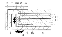
- the thermal diffusion / heat insulation sheet 17 is provided between the light source substrate 12 and the back side casing 31, the following effects are obtained. That is, as in Comparative Example 5 shown in FIG. 12, when the thermal diffusion / heat insulation sheet 17 is not provided, cooling of the heat (X1) generated in the vicinity of the light sources 13A1 and 13B1 becomes insufficient. In addition, heat may be transmitted from the rear housing 31 to the outside, and the exterior temperature may exceed the standard (X2).
- the present embodiment as shown in FIG. 13, by providing a thermal diffusion / heat insulation sheet 17 between the light source substrate 12 and the back-side casing 31, the exterior from the light sources 13 ⁇ / b> A ⁇ b> 1 and 13 ⁇ / b> B ⁇ b> 1. Heat can be efficiently transferred to the heat radiating member 16 while blocking heat conduction to (S1). Therefore, reliability can be improved.
- the circuit unit for driving the light sources 13A1 and 13B1 is disposed on the light source substrate 12 that supports the plurality of light sources 13A1 and 13B1, and the circuit unit of the light source substrate 12 is disposed.
- the portion 121 is disposed to face the back surface of the light guide unit 11.
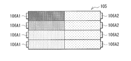
- FIGS. 16, 17A and 17B are diagrams for explaining a light extraction pattern of the light guide plate according to the first modification.
- the light emitting area is subdivided in each of the light guide plates 11A and 11B depending on the presence / absence of the pattern for each region.
- the light emitting area is subdivided depending on the pattern density. Yes.
- the pattern density of the light guide plate 11A is shown as an example.
- the light source 13A1 is driven as schematically shown in FIG. 15A.
- the boundary p1 between the area Da1 and the area Da2 stands out, resulting in an unnatural display.
- FIG. 15B when the light source 13A2 is driven to illuminate the area Da3 of the light guide plate 11A, the boundary p2 between the area Da2 and the area Da3 stands out, resulting in an unnatural display.
- the pattern is arranged not only in the areas Da1 and Da3 but also in the area Da2 of the light guide plate 11A (the density changes gently). Accordingly, as schematically shown in FIG. 17A, when the light source 13A1 is driven to illuminate the area Da1 of the light guide plate 11A, the boundary between the area Da1 and the area Da2 is moderately blurred and natural display is obtained. Similarly, as schematically shown in FIG. 17B, when the light source 13A2 is driven to illuminate the area Da3 of the light guide plate 11A, the boundary between the area Da2 and the area Da3 is moderately blurred and a natural display is obtained.
- the light emitting area may be subdivided according to the pattern density of the light guide plates 11A and 11B.
- the pattern density changes gradually at the boundary between the light emitting areas. This is more advantageous for improving image quality.
- FIG. 18 illustrates a main configuration of a backlight unit according to the second modification.
- the bent shape is not limited to this and can be various shapes.
- the shape bent in two places may be sufficient like the light source board
- the light source substrate 12A includes a portion 121 where the circuit portions of the light sources 13A and 13B1 are disposed, a portion 122 where the light sources 13A1 and 13B1 are mounted (arranged), and a light emitting surface S12 of the light guide plate 11A. And a portion 123 disposed so as to face to each other. It is bent between the portions 121 and 122 and has a bent shape that is bent between the portions 122 and 123. The portion 123 is disposed to face the light exit surface of the light guide unit 11.
- FIG. 19 illustrates a main configuration of a backlight unit according to Modification 3.
- the light sources 13A1 and 13B1 made of top-emitting LEDs have been described as examples.
- a light source (light source 130C) including an edge-emitting LED is used. Good.
- the light source 130C is, for example, an edge-emitting (side view type) LED having a plurality of (here, two) light emitting regions (active layers) 130C1 and 130C2 at different height positions.
- a light source 130C is arranged on the light source substrate 12B.
- the light source substrate 12B supports the light source 130C and has a portion 121 on which a circuit unit is disposed. Also in this modification, the portion 121 of the light source substrate 12B is disposed to face the back surface of the light guide unit 11. However, the light source substrate 12B has a flat plate shape, and the light source 130C is disposed on the extended surface of the portion 121.
- the light emitting regions 130C1 and 130C2 are connected to separate wirings 130a and 130b, respectively, and are configured to be individually driven to emit light.
- the light source substrate 12B does not have to be bent. Even if the light source substrate 12B is not bent, the space on the back side of the light guide unit 11 can be effectively used to reduce the thickness of the entire apparatus. Therefore, an effect equivalent to that of the above embodiment can be obtained.
- FIG. 21B, and FIG. 22 show the main configuration of a backlight unit according to Modification 4.
- the light sources 13A1 and 13B1 made of top-emitting LEDs have been described as examples.
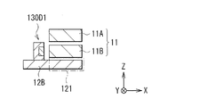
- light sources 130D1 and 130D2 including edge-emitting LEDs are used. May be.
- Each of the light sources 130D1 and 130D2 is, for example, an edge-emitting type (side view type) LED having light emitting regions (active layers) at different height positions.
- Such light sources 130D1 and 130D2 are both disposed on the same light source substrate 12B.
- the light source substrate 12B supports the light sources 130D1 and 130D2 and includes a portion 121 on which a circuit unit is disposed. Also in this modification, the portion 121 of the light source substrate 12B is disposed to face the back surface of the light guide unit 11. Further, as shown in FIG. 22, the light sources 130D1 and 130D2 are alternately arranged, for example, along the Y direction.
- the light source substrate 12B may not be bent. Even if the light source substrate 12B is not bent, the space on the back side of the light guide unit 11 can be effectively used to reduce the thickness of the entire apparatus. Therefore, an effect equivalent to that of the above embodiment can be obtained.
- FIG. 23 illustrates a main configuration of a backlight unit according to Modification 5.
- the light sources 13A1 and 13B1 made of top-emitting LEDs have been described as examples.
- light sources 130D1 and 130D2 including edge-emitting LEDs are used. May be.
- Each of the light sources 130D1 and 130D2 is, for example, an edge-emitting type (side view type) LED having a light emitting region (active layer) at different heights, as in the fourth modification.
- Such light sources 130D1 and 130D2 are both disposed on the same light source substrate 12B.
- the light source substrate 12B supports the light sources 130D1 and 130D2 and includes a portion 121 on which a circuit unit is disposed. Also in this modification, the portion 121 of the light source substrate 12B is disposed to face the back surface of the light guide unit 11.
- the light sources 130D1 and 130D2 are arranged at the front and rear positions in the X direction.
- the light incident portions S11 and S21 of the light guide plates 11A and 11B are arranged at positions corresponding to the positions of the light sources 130D1 and 130D2.
- the light source substrate 12B may not be bent. Even if the light source substrate 12B is not bent, the space on the back side of the light guide unit 11 can be effectively used to reduce the thickness of the entire apparatus. Therefore, an effect equivalent to that of the above embodiment can be obtained.
- FIG. 24 illustrates a main configuration of a backlight unit according to Modification 6.
- a configuration example in which a light source composed of an edge-emitting LED and a flat light source substrate are used has been described.
- a light source 13A1 including a top-emitting LED. , 13B1 and a flat light source substrate 12B may be used in combination.
- the light source substrate 12B supports the light sources 13A1 and 13B1 and has a portion 121 on which a circuit portion is arranged. Also in this modification, the portion 121 of the light source substrate 12B is disposed to face the back surface of the light guide unit 11. However, in this modification, inclined surfaces t11 and t21 are formed in the light incident portions S11 and S21 of the light guide plates 11A1 and 11A2. Thereby, the light emitted from the light sources 13A1 and 13B1 in the positive direction in the Z direction is reflected by the inclined surfaces t11 and t21 and guided in the XY plane direction of the light guide plates 11A1 and 11A2.
- the inclined surfaces are formed in the light incident portions S11 and S21 has been described, but a curved surface may be formed.
- FIG. 25 illustrates a main configuration of a backlight unit according to Modification 7.
- a light source composed of a top-emitting LED is used and a light source composed of an edge-emitting LED is used in Modifications 3 to 5, respectively.
- These top-emitting LEDs and end-emitting LEDs may be used in combination.
- the top-emitting light source 13B1 may be disposed facing the light incident portion of the light guide plate 11A2 having the inclined surface t21, and the end-emitting light source 130D2 may be disposed facing the light incident portion of the light guide plate 11A.
- the light sources 13B1 and 130D2 can be arranged on the flat light source substrate 12B.
- FIG. 26 illustrates a main configuration of a backlight unit according to Modification 8.
- the light shielding member 18 is provided so as to cover the periphery of the light incident portions of the light guide plates 11A and 11B.
- the light guide plates 11A and 11B instead of the light shielding member 18 or in addition to the light shielding member 18, the light guide plates 11A and 11B.
- a mirror sheet 18B having a light shielding function and a reflecting function may be disposed between them.
- the mirror sheet 18B is composed of, for example, a mirror surface sheet, a metal thin film, or the like.
- the mirror sheet 18B is interposed between the light sources 13A1 and 13B1 and is disposed between the light guide plates 11A and 11B. As described above, by using the mirror sheet 18B, the vicinity of the light incident portion between the light guide plates 11A and 11B can be reflected while being shielded.
- FIG. 27 illustrates a main configuration of a backlight unit according to Modification 9.
- the light shielding member 18 is provided so as to cover the periphery of the light incident portions of the light guide plates 11A and 11B.
- the light guide plates 11A and 11B instead of the light shielding member 18 or in addition to the light shielding member 18, the light guide plates 11A and 11B.
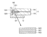
- a multilayer sheet 18C having a light shielding function and a reflection function may be disposed therebetween.
- the multilayer sheet 18C is interposed between the light sources 13A1 and 13B1 and is disposed between the light guide plates 11A and 11B.
- the multilayer sheet 18C is, for example, provided with a pair of white layers 18c2 with a black layer 18c1 interposed therebetween.
- FIG. 28 illustrates a main configuration of a backlight unit according to Modification Example 10.
- the light shielding member 18 is provided so as to cover the periphery of the light incident portions of the light guide plates 11A and 11B.
- a part of the light source substrate 12 replaces a part of the light shielding member 18. You may also serve.
- the portion 121 of the light source substrate 12 is configured to perform a light shielding function on the back side of the light guide plate 11B.
- the flange portion 18a constituting the light shielding member 18 is disposed between the light emitting surface side of the light guide plate 11A and between the light guide plates 11A and 11B. In this way, a part of the light source substrate 12 may also serve as a part of the light shielding member 18, and such a configuration is advantageous for further thinning.
- FIG. 29 illustrates a main configuration of a backlight unit according to the eleventh modification.
- the light shielding member 18 is provided so as to cover the periphery of the light incident portions of the light guide plates 11A and 11B.
- a part of the light source substrate 12A partially covers the light shielding member 18. You may also serve.
- the portion 121 of the light source substrate 12A according to the second modification is configured to have a light shielding function on the back side of the light guide plate 11B. Further, the portion 123 of the light source substrate 12A is configured to have a light shielding function on the light emitting surface side of the light guide plate 11A. Between the light guide plates 11A and 11B, a flange portion 18a constituting the light shielding member 18 is arranged as in the above embodiment. As described above, a part of the light source substrate 12A may also serve as a part of the light shielding member 18, and such a configuration is advantageous for further thinning.
- FIG. 30 illustrates a main configuration of a backlight unit according to Modification 12.
- the bent shape is not limited to this and can be various shapes.
- the end portion on the back side of the light guide unit 11 may be bent in a Z shape (Z shape).
- the light source substrate 12C has a bent portion 12c1 bent in a Z shape so that the end portion of the light source substrate 12C approaches the light guide portion 11.
- the heat radiating member 16 is thermally connected adjacent to the bent portion 12c1 from the outside.
- the heat radiating member 16 is disposed in the space generated by the bent portion 12c1.
- the shape of the light source substrate can be various bent shapes. Further, the number of bent portions is not limited to one to three, and may be four or more. Further, the corner portion formed by bending may be rounded.
- the light source substrate can take various shapes depending on the shape of the exterior and the layout of other components.
- FIG. 31A schematically shows a reflection pattern of a light guide plate (upper light guide plate 11C) according to Modification 13.
- FIG. 31B schematically shows a reflection pattern of a light guide plate (lower light guide plate 11D) according to Modification 13.
- the arrangement location of the light source is not limited to this.
- the light source may be disposed facing the end surface corresponding to the long rectangular side of the light guide plate, or the light source may be disposed on the end surface corresponding to the four rectangular sides.
- a configuration in which a light source is disposed so as to face end surfaces corresponding to two long sides will be described.
- the light guide unit 11 is composed of two light guide plates 11C and 11D, and the light guide plate 11C is stacked on the light guide plate 11D.
- Each of the light guide plates 11C and 11D has a light incident portion (S11, S21) and a light exit surface.
- light extraction patterns are formed in different selective areas.
- end faces corresponding to the two long sides of the rectangular shape of the light guide plates 11C and 11D are the light incident portions S11 and S21.
- the reflection surface of the light guide plate 11C is divided into four regions Dc1 to Dc4 in the XY plane, and two of these regions Dc1 and Dc3 are divided into other regions.
- a pattern capable of extracting more light is formed in the areas Dc1 and Dc3, the pattern density (dot density) is higher than in the areas Dc2 and Dc4.
- the reflection surface of the light guide plate 11D is divided into four regions Dd1 to Dd4 in the XY plane, and two of these regions Dd2 and Dd4 have other regions.
- each of the light guide plates 11C and 11D is divided into several regions, and light extraction patterns are densely formed in selective regions that are different between the upper and lower light guide plates among the divided regions. Yes.
- the light extraction patterns are arranged such that, for example, dots formed of concave portions or convex portions gradually increase in density as they move away from the light source. It is desirable that
- a plurality of light sources are opposed to the end faces (light incident portions S11 and S21) of these light guide plates 11C and 11D.
- the end surfaces extending along the X direction of the light guide plates 11C and 11D are the light incident portions S11 and S21.
- the case where eight light sources are arranged opposite to each other is illustrated, and the light sources arranged on the end surface on the Y direction positive side (upper side in the drawing) of the light guide plate 11C are the light sources 13C1 (13C11 to 13C18).
- the light source disposed on the end face on the Y direction negative side is a light source 13C2 (13C21 to 13C28).
- the light source disposed on the Y-direction positive end surface of the light guide plate 11D is the light source 13D1 (13D11 to 13D18), and the light source disposed on the Y-direction negative end surface is the light source 13D2 (13D21 to 13D28).
- the light and dark (white to black display) of the area Dc1 is set by driving the light sources 13C11 to 13C18, and the light and dark (white to black display) of the area Da3 drives the light sources 13C21 to 13C28.
- each of the light sources 13C11 to 13C18 and 13C21 to 13C28 is driven separately, so that the light emitting area is further divided in the regions Dc1 and Dc3.
- the light and dark (white to black display) of the region Dd2 is set by driving the light sources 13D11 to 13D18, and the light and dark (white to black display) of the region Dd4 is driven to the light sources 13D21 to 13D28.
- each of the light sources 13D11 to 13D18 and 13D21 to 13D28 is driven separately, so that the light emitting area is further divided in the regions Db2 and Db4.
- the region Dc1 can be illuminated by the lighting of the light source 13C1 (13C11 to 13C18) (light emitting areas c11 to c14).
- the area Dc3 can be illuminated by the lighting of the light source 13C2 (13C21 to 13C28) (light emitting areas c21 to c24).
- the light guide plate 11D can illuminate the region Dd2 by turning on the light source 13D1 (13D11 to 13D18) (light emitting areas d11 to d14).
- the region Dd4 can be illuminated by the lighting of the light source 13D2 (13D21 to 13D28) (light emitting areas d21 to d24).
- the light guide unit 11 By individually setting the light emission intensity of each of the light emitting areas c11 to c14, c21 to c24, d11 to d14, and d21 to d24 of the light guide plates 11C and 11D, the light guide unit 11 as a whole as in the above embodiment. As described above, the light emitting area can be subdivided (for example, divided into 16 as shown in FIG. 9) to perform partial driving.
- the present disclosure has been described with the embodiment and the modification.
- the present disclosure is not limited to the above-described embodiment and the like, and various modifications are possible.
- the material of each member described in the above embodiment and the like is not limited, and other materials may be used.
- the number and shape of the light guide plates described in the above embodiments are not limited to those described above.
- the number of light sources, the arrangement location, the pitch, and the like are not limited to those described above.
- the illumination device of the present disclosure is not limited to the backlight unit of the display device as described above, and can be applied to, for example, illumination devices as shown in FIGS.
- the lighting device shown in FIGS. 33 and 34 is a tabletop or floor-standing lighting device, and includes a lighting unit 843 having the same configuration as the backlight unit 10 of the above embodiment.
- the illumination part 843 is attached to the support
- the light guide part 11 (the light guide plates 11A and 11B) can have a curved shape, such as a cylindrical shape shown in FIG. 33 or a curved shape shown in FIG.
- the 35 includes an illuminating unit 844 having a configuration similar to that of the backlight unit 10 of the above embodiment.
- One or more illumination units 844 are arranged on the ceiling 850A of the building at a predetermined interval. Note that the illumination unit 844 is not limited to the ceiling 850A, but may be installed on a wall 850B, a floor (not shown), or the like depending on the application. Moreover, you may use not only indoors but outdoors.
- Each of the light guides includes a light incident part and a light exit surface, and includes a plurality of light guide plates stacked along the thickness direction.
- a plurality of light sources that emit light toward the light incident portion of each light guide plate of the light guide portion;
- substrates is arrange
- the substrate includes the first portion and a second portion disposed to face the light incident portion, and has a bent shape that is bent between the first portion and the second portion.
- the lighting device according to (1) wherein a plurality of light sources are arranged on the second portion of the substrate.
- a structure having at least one of a light shielding function and a reflecting function is provided between the plurality of light guide plates, covering a part of the light guide plate on the light incident part side.
- the illuminating device as described in (2) is a lighting apparatus as described in said (3) which has a part which latches the shift to the said light source side of the said light guide plate while ensuring the clearance gap between the said light guide plate and the said light source.
- the said structure is comprised from the gray resin material.
- the substrate includes the first portion, a second portion disposed to face the light incident portion, and a third portion disposed to face the front surface of the light guide portion. Having a bent shape bent between a portion and the second portion and between the second portion and the third portion, The lighting device according to (1), wherein the plurality of light sources are arranged on the second portion of the substrate.
- a composite sheet including a heat diffusible layer and a heat insulating layer is disposed on each surface side of the heat radiating member and the substrate and straddling the heat radiating member and the substrate.
- the lighting device described in 1. (9) The lighting device according to (7) or (8), wherein the heat dissipation member is thermally connected to a surface of the substrate on which the light source is mounted. (10) The edge of the substrate is bent in a Z shape, The heat dissipation member is disposed in a space generated by the Z-shaped bending of the substrate, and is thermally connected to the substrate. (7) The device according to any one of (9) to (9), Lighting device.
- the lighting device according to any one of (1) to (10), wherein the light source is a top-emitting light emitting diode.
- the substrate has a flat plate shape, The lighting device according to (1), wherein the plurality of light sources are arranged on an extended surface of the first portion of the substrate.
- the plurality of light sources are composed of edge-emitting light emitting diodes, The lighting device according to (12), wherein the light emitting diode has a plurality of light emitting regions each formed at a different height position.
- each of the plurality of light sources is an edge-emitting light emitting diode, and a height of a light emitting region is different for each light guide plate.
- the light source is a top-emitting LED.
- a functional sheet having both a light shielding function and a reflection function is disposed on a part of the light incident plate side of the light guide plate.
- the functional sheet is a mirror-finished sheet, a metal thin film, or a laminated film in which a light shielding layer is sandwiched between a pair of reflective layers.
- Each of the plurality of light guide plates has light extraction patterns arranged in a plurality of selective regions in a plane parallel to the light emitting surface at a higher density than other regions.
- the lighting device according to any one of the above.
- Each of the light guides includes a light incident part and a light exit surface, and includes a plurality of light guide plates stacked along the thickness direction.
- a plurality of light sources that emit light toward the light incident portion of each light guide plate of the light guide portion; And a substrate on which a circuit unit for driving each light source is arranged, and supporting the plurality of light sources,
- the display apparatus provided with the illuminating device by which the 1st part by which the said circuit part of the said board
Abstract
Description
1.実施の形態(光源基板を屈曲させて配置したバックライトユニットを備えた表示装置の例)
2.変形例1(導光板の反射パターンの他の例)
3.変形例2(基板の屈曲形状の他の例)
4.変形例3~5(端面発光型の光源を用いた場合の例)
5.変形例6(導光板の光入射部に形状を付与した例)
6.変形例7(上面発光型と端面発光型の光源とを組み合わせて用いた場合の例)
7.変形例8,9(導光板間に機能性シートを配置した場合の例)
8.変形例10,11(光源基板の一部が遮光部材を兼ねる場合の例)
9.変形例12(基板の端部がZ状に曲げられた場合の例)
10.変形例13(光源配置の他の例)
[構成]
図1は、本開示の一実施の形態に係る表示装置(表示装置1)の断面構成を表したものである。この表示装置1は、例えば液晶ディスプレイであり、バックライトユニット10と、液晶パネルユニット20と、前面側筐体30と、背面側筐体31とを備えている。尚、図1に示した構成は、表示装置1の一部(端部)に相当するものである。尚、本実施の形態のバックライトユニット10が、本開示における「照明装置」の一具体例に相当する。
バックライトユニット10は、例えば、複数(ここでは2つ)の導光板11A,11Bを含む導光部11と、導光板11A,11B毎に設けられた光源(13A1,13B1)と、光源基板12と、光学シート14と、反射シート15と、放熱部材16と、熱拡散/断熱シート17と、遮光部材18とを備えている。
本実施の形態の表示装置1では、バックライトユニット10において、光源13A1,13B1等から発せられた光が導光板11A,11B内を伝搬した後、光出射面から出射され、光学シート14を透過する。この光学シート14を透過した光が、液晶パネルユニット20を照明する。液晶パネルユニット20では、映像信号に基づいて、バックライトユニット10から照射された光が変調され、映像が表示される。
図14,図15Aおよび図15Bは、変形例1に係る導光板の光取り出し用のパターンを説明するためのものである。図16,図17Aおよび図17Bは、変形例1に係る導光板の光取り出し用のパターンを説明するためのものである。上記実施の形態では、導光板11A,11Bのそれぞれにおいて、領域毎のパターンの有無によって、発光エリアを細分化したが、本変形例では、パターンの密度の高低によって、発光エリアが細分化されている。尚、これらの図では、導光板11Aのパターン密度を一例として示している。
図18は、変形例2に係るバックライトユニットの要部構成を表したものである。上記実施の形態では、光源基板がL字状に屈曲した形状である場合を説明したが、屈曲形状はこれに限定されず、様々な形状とすることができる。例えば、本変形例の光源基板12Aのように、2箇所において折り曲げられた形状であってもよい。
図19は、変形例3に係るバックライトユニットの要部構成を表したものである。上記実施の形態では、上面発光型のLEDからなる光源13A1,13B1を例に挙げて説明したが、本変形例のように、端面発光型のLEDを含む光源(光源130C)が用いられてもよい。
図21A,図21Bおよび図22は、変形例4に係るバックライトユニットの要部構成を表したものである。上記実施の形態では、上面発光型のLEDからなる光源13A1,13B1を例に挙げて説明したが、本変形例のように、端面発光型のLEDを含む光源(光源130D1,130D2)が用いられてもよい。
図23は、変形例5に係るバックライトユニットの要部構成を表したものである。上記実施の形態では、上面発光型のLEDからなる光源13A1,13B1を例に挙げて説明したが、本変形例のように、端面発光型のLEDを含む光源(光源130D1,130D2)が用いられてもよい。
図24は、変形例6に係るバックライトユニットの要部構成を表したものである。上記変形例3~5では、端面発光型のLEDからなる光源と、平板状の光源基板とが用いられる構成例を挙げたが、本変形例のように、上面発光型のLEDを含む光源13A1,13B1と、平板状の光源基板12Bとを組み合わせて用いてもよい。
図25は、変形例7に係るバックライトユニットの要部構成を表したものである。上記実施の形態では、上面発光型のLEDからなる光源を、上記変形例3~5では、端面発光型のLEDからなる光源を、それぞれ用いた場合について説明したが、本変形例のように、これらの上面発光型のLEDと端面発光型のLEDとを組み合わせて用いても構わない。
図26は、変形例8に係るバックライトユニットの要部構成を表したものである。上記実施の形態では、導光板11A,11Bの光入射部の周囲を覆うように遮光部材18を設けたが、この遮光部材18に代えて、あるいは遮光部材18に加えて、導光板11A,11B間に、遮光機能と反射機能とをもつミラーシート18Bを配置してもよい。
図27は、変形例9に係るバックライトユニットの要部構成を表したものである。上記実施の形態では、導光板11A,11Bの光入射部の周囲を覆うように遮光部材18を設けたが、この遮光部材18に代えて、あるいは遮光部材18に加えて、導光板11A,11B間に、遮光機能と反射機能とをもつ複層シート18Cを配置してもよい。
図28は、変形例10に係るバックライトユニットの要部構成を表したものである。上記実施の形態では、導光板11A,11Bの光入射部の周囲を覆うように遮光部材18を設けたが、本変形例のように、光源基板12の一部が遮光部材18の一部を兼ねていてもよい。
図29は、変形例11に係るバックライトユニットの要部構成を表したものである。上記実施の形態では、導光板11A,11Bの光入射部の周囲を覆うように遮光部材18を設けたが、本変形例のように、光源基板12Aの一部が遮光部材18の一部を兼ねていてもよい。
図30は、変形例12に係るバックライトユニットの要部構成を表したものである。上記実施の形態では、光源基板がL字状に屈曲した形状である場合を説明したが、屈曲形状はこれに限定されず、様々な形状とすることができる。例えば、本変形例の光源基板12Cのように、導光部11の背面側の端部がZ字状(Z状)に折り曲げられていてもよい。
図31Aは、変形例13に係る導光板(上側の導光板11C)の反射パターンを模式的に表したものである。図31Bは、変形例13に係る導光板(下側の導光板11D)の反射パターンを模式的に表したものである。上記実施の形態等では、導光板11A,11Bの矩形状の短辺に対応する端面を光入射部S11,S21とした構成について説明したが、光源の配置箇所はこれに限定されない。例えば、導光板の矩形状の長辺に対応する端面に対向して光源が配置されていてもよいし、矩形状の4辺に対応する端面に光源が配置されていても構わない。ここでは、一例として、2つの長辺に対応する端面に対向して光源が配置された構成について説明する。
(1)
各々が光入射部と光出射面とを有すると共に、厚み方向に沿って積層された複数の導光板を含む導光部と、
前記導光部の各導光板の前記光入射部へ向けて光を出射する複数の光源と、
前記複数の光源を支持すると共に、各光源を駆動するための回路部が配置された基板と
を備え、
前記基板のうちの前記回路部が配置された第1部分が、前記導光部の背面に対向して配置されている
照明装置。
(2)
前記基板は、前記第1部分と、前記光入射部に対向して配置された第2部分とを含むと共に、前記第1部分と前記第2部分との間において折り曲げられた屈曲形状を有し、
前記基板の前記第2部分に、複数の光源が配置されている
上記(1)に記載の照明装置。
(3)
前記複数の導光板の同士の間において、前記導光板の前記光入射部側の一部を覆うと共に、遮光機能および反射機能のうちの少なくとも一方を有する構造体が設けられている
上記(1)または(2)に記載の照明装置。
(4)
前記構造体は、前記導光板と前記光源との間隙を確保すると共に、前記導光板の前記光源側へのシフトを係止する部分を有する
上記(3)に記載の照明装置。
(5)
前記構造体は、灰色の樹脂材料から構成されている
上記(3)または(4)に記載の照明装置。
(6)
前記基板は、前記第1部分と、前記光入射部に対向して配置された第2部分と、前記導光部の前面に対向して配置された第3部分とを含むと共に、前記第1部分と前記第2部分との間および前記第2部分と前記第3部分との間のそれぞれにおいて折り曲げられた屈曲形状を有し、
前記基板の前記第2部分に前記複数の光源が配置されている
上記(1)に記載の照明装置。
(7)
前記導光部の背面側に、前記基板と熱的に接続して配置された放熱部材を備えた
上記(1)ないし(6)のうちのいずれか1つに記載の照明装置。
(8)
前記放熱部材と前記基板との各一面側に、前記放熱部材と前記基板とに跨って配置されると共に、熱拡散性層と断熱性層とを含む複合シートが配置されている
上記(7)に記載の照明装置。
(9)
前記放熱部材は、前記基板の前記光源が実装されている面に熱的に接続されている
上記(7)または(8)に記載の照明装置。
(10)
前記基板の端部は、Z状に折り曲げられており、
前記放熱部材は、前記基板のZ状の折り曲げによって生じた空間に配置されると共に、前記基板に熱的に接続されている
上記(7)ないし(9)のうちのいずれか1つに記載の照明装置。
(11)
前記光源は、上面発光型の発光ダイオードである
上記(1)ないし(10)のうちのいずれか1つに記載の照明装置。
(12)
前記基板は、平板形状を有し、
前記基板の前記第1部分の延長面上に、前記複数の光源が配置されている
上記(1)に記載の照明装置。
(13)
前記複数の光源は、端面発光型の発光ダイオードから構成され、
前記発光ダイオードは、各々が異なる高さ位置に形成された複数の発光領域を有する
上記(12)に記載の照明装置。
(14)
前記複数の光源はそれぞれ、端面発光型の発光ダイオードであり、前記導光板毎に発光領域の高さが異なっている
上記(12)に記載の照明装置。
(15)
前記光源は、上面発光型の発光ダイオードであり、
前記導光板の前記光入射部は、斜面または曲面を有する
上記(12)に記載の照明装置。
(16)
前記複数の導光板の同士の間において、前記導光板の前記光入射部側の一部に、遮光機能と反射機能との両方をもつ機能性シートが配置されている
上記(1)ないし(15)のうちのいずれか1つに記載の照明装置。
(17)
前記機能性シートは、鏡面調シート、金属薄膜、または、一対の反射層間に遮光層を挟んでなる積層膜である
上記(16)に記載の照明装置。
(18)
前記複数の導光板はそれぞれ、前記光出射面に平行な面内における複数の選択的な領域に他の領域よりも高い密度で配置された光取り出し用のパターンを有する
上記(1)ないし(17)のうちのいずれか1つに記載の照明装置。
(19)
各々が光入射部と光出射面とを有すると共に、厚み方向に沿って積層された複数の導光板を含む導光部と、
前記導光部の各導光板の前記光入射部へ向けて光を出射する複数の光源と、
前記複数の光源を支持すると共に、各光源を駆動するための回路部が配置された基板と
を備え、
前記基板のうちの前記回路部が配置された第1部分が、前記導光部の背面に対向して配置されている
照明装置を備えた表示装置。
Claims (19)
- 各々が光入射部と光出射面とを有すると共に、厚み方向に沿って積層された複数の導光板を含む導光部と、
前記導光部の各導光板の前記光入射部へ向けて光を出射する複数の光源と、
前記複数の光源を支持すると共に、各光源を駆動するための回路部が配置された基板と
を備え、
前記基板のうちの前記回路部が配置された第1部分が、前記導光部の背面に対向して配置されている
照明装置。 - 前記基板は、前記第1部分と、前記光入射部に対向して配置された第2部分とを含むと共に、前記第1部分と前記第2部分との間において折り曲げられた屈曲形状を有し、
前記基板の前記第2部分に、複数の光源が配置されている
請求項1に記載の照明装置。 - 前記複数の導光板の同士の間において、前記導光板の前記光入射部側の一部を覆うと共に、遮光機能および反射機能のうちの少なくとも一方を有する構造体が設けられている
請求項1に記載の照明装置。 - 前記構造体は、前記導光板と前記光源との間隙を確保すると共に、前記導光板の前記光源側へのシフトを係止する部分を有する
請求項3に記載の照明装置。 - 前記構造体は、灰色の樹脂材料から構成されている
請求項3に記載の照明装置。 - 前記基板は、前記第1部分と、前記光入射部に対向して配置された第2部分と、前記導光部の前面に対向して配置された第3部分とを含むと共に、前記第1部分と前記第2部分との間および前記第2部分と前記第3部分との間のそれぞれにおいて折り曲げられた屈曲形状を有し、
前記基板の前記第2部分に前記複数の光源が配置されている
請求項1に記載の照明装置。 - 前記導光部の背面側に、前記基板と熱的に接続して配置された放熱部材を備えた
請求項1に記載の照明装置。 - 前記放熱部材と前記基板との各一面側に、前記放熱部材と前記基板とに跨って配置されると共に、熱拡散性層と断熱性層とを含む複層シートが配置されている
請求項7に記載の照明装置。 - 前記放熱部材は、前記基板の前記光源が実装されている面に熱的に接続されている
請求項7に記載の照明装置。 - 前記基板の端部は、Z状に折り曲げられており、
前記放熱部材は、前記基板のZ状の折り曲げによって生じた空間に配置されると共に、前記基板に熱的に接続されている
請求項7に記載の照明装置。 - 前記光源は、上面発光型の発光ダイオードである
請求項1に記載の照明装置。 - 前記基板は、平板形状を有し、
前記基板の前記第1部分の延長面上に、前記複数の光源が配置されている
請求項1に記載の照明装置。 - 前記複数の光源は、端面発光型の発光ダイオードから構成され、
前記発光ダイオードは、各々が異なる高さ位置に形成された複数の発光領域を有する
請求項12に記載の照明装置。 - 前記複数の光源はそれぞれ、端面発光型の発光ダイオードであり、前記導光板毎に発光領域の高さが異なっている
請求項12に記載の照明装置。 - 前記光源は、上面発光型の発光ダイオードであり、
前記導光板の前記光入射部は、斜面または曲面を有する
請求項12に記載の照明装置。 - 前記複数の導光板の同士の間において、前記導光板の前記光入射部側の一部に、遮光機能と反射機能との両方をもつ機能性シートが配置されている
請求項1に記載の照明装置。 - 前記機能性シートは、鏡面調シート、金属薄膜、または、一対の反射層間に遮光層を挟んでなる積層膜である
請求項16に記載の照明装置。 - 前記複数の導光板はそれぞれ、前記光出射面に平行な面内における複数の選択的な領域に他の領域よりも高い密度で配置された光取り出し用のパターンを有する
請求項1に記載の照明装置。 - 各々が光入射部と光出射面とを有すると共に、厚み方向に沿って積層された複数の導光板を含む導光部と、
前記導光部の各導光板の前記光入射部へ向けて光を出射する複数の光源と、
前記複数の光源を支持すると共に、各光源を駆動するための回路部が配置された基板と
を備え、
前記基板のうちの前記回路部が配置された第1部分が、前記導光部の背面に対向して配置されている
照明装置を備えた表示装置。
Priority Applications (4)
| Application Number | Priority Date | Filing Date | Title |
|---|---|---|---|
| CN201680018864.3A CN107533256B (zh) | 2015-04-06 | 2016-03-01 | 照明装置与显示装置 |
| EP16776345.7A EP3282174B1 (en) | 2015-04-06 | 2016-03-01 | Lighting device and display device |
| US15/562,106 US11209585B2 (en) | 2015-04-06 | 2016-03-01 | Illuminating unit and display apparatus |
| JP2017511495A JP6774939B2 (ja) | 2015-04-06 | 2016-03-01 | 照明装置および表示装置 |
Applications Claiming Priority (4)
| Application Number | Priority Date | Filing Date | Title |
|---|---|---|---|
| JP2015-077327 | 2015-04-06 | ||
| JP2015077327 | 2015-04-06 | ||
| JP2015227573 | 2015-11-20 | ||
| JP2015-227573 | 2015-11-20 |
Publications (1)
| Publication Number | Publication Date |
|---|---|
| WO2016163176A1 true WO2016163176A1 (ja) | 2016-10-13 |
Family
ID=57073124
Family Applications (1)
| Application Number | Title | Priority Date | Filing Date |
|---|---|---|---|
| PCT/JP2016/056202 WO2016163176A1 (ja) | 2015-04-06 | 2016-03-01 | 照明装置および表示装置 |
Country Status (5)
| Country | Link |
|---|---|
| US (1) | US11209585B2 (ja) |
| EP (1) | EP3282174B1 (ja) |
| JP (1) | JP6774939B2 (ja) |
| CN (1) | CN107533256B (ja) |
| WO (1) | WO2016163176A1 (ja) |
Cited By (8)
| Publication number | Priority date | Publication date | Assignee | Title |
|---|---|---|---|---|
| WO2019021952A1 (ja) * | 2017-07-28 | 2019-01-31 | シャープ株式会社 | 照明装置及び表示装置 |
| KR20190086312A (ko) * | 2018-01-12 | 2019-07-22 | 엘지전자 주식회사 | 차량용 램프 및 차량 |
| CN110174797A (zh) * | 2018-02-21 | 2019-08-27 | 夏普株式会社 | 显示装置及电视信号接收器 |
| JP2019153444A (ja) * | 2018-03-02 | 2019-09-12 | 株式会社フジカケ | ハニカムパネル |
| JP2020060682A (ja) * | 2018-10-10 | 2020-04-16 | 株式会社ジャパンディスプレイ | 表示装置 |
| US10705276B2 (en) | 2018-06-22 | 2020-07-07 | Sharp Kabushiki Kaisha | Lighting device and display device |
| JP2021022496A (ja) * | 2019-07-29 | 2021-02-18 | ミネベアミツミ株式会社 | 面状照明装置 |
| US11163107B2 (en) | 2020-03-10 | 2021-11-02 | Sharp Kabushiki Kaisha | Lighting device and display device |
Families Citing this family (7)
| Publication number | Priority date | Publication date | Assignee | Title |
|---|---|---|---|---|
| CN108897166B (zh) * | 2018-07-19 | 2021-06-04 | 东莞市豪顺精密科技有限公司 | 一种实现hdr分区的侧入式背光模组及液晶显示装置 |
| US20200264479A1 (en) * | 2019-02-20 | 2020-08-20 | Sharp Kabushiki Kaisha | Lighting device and display device |
| WO2021050668A1 (en) | 2019-09-10 | 2021-03-18 | Hubbell Incorporated | Canopy luminaire |
| JP2022156704A (ja) * | 2021-03-31 | 2022-10-14 | 株式会社ジャパンディスプレイ | 通信装置および通信方法 |
| DE102021204507B3 (de) | 2021-05-05 | 2022-09-29 | Continental Automotive Technologies GmbH | Baugruppe für eine Hintergrundbeleuchtung eines Displays und Display mit einer Hintergrundbeleuchtung mit einer solchen Baugruppe |
| JP2023039702A (ja) * | 2021-09-09 | 2023-03-22 | 株式会社ジャパンディスプレイ | 表示装置 |
| CN116609974A (zh) * | 2023-05-31 | 2023-08-18 | 重庆惠科金渝光电科技有限公司 | 背光源组件、双面显示模组以及双面显示装置 |
Citations (6)
| Publication number | Priority date | Publication date | Assignee | Title |
|---|---|---|---|---|
| JP2006201215A (ja) * | 2005-01-18 | 2006-08-03 | Seiko Epson Corp | 電気光学装置、電気光学装置の製造方法、電子機器 |
| JP2008112739A (ja) * | 2006-09-21 | 2008-05-15 | Sharp Corp | バックライト装置 |
| JP2008171797A (ja) * | 2006-12-13 | 2008-07-24 | Nichia Chem Ind Ltd | バックライトユニット |
| JP2010204256A (ja) * | 2009-03-02 | 2010-09-16 | Hitachi Displays Ltd | 液晶表示装置 |
| JP2011530791A (ja) * | 2008-08-14 | 2011-12-22 | ジョンソン コントロールズ テクノロジー カンパニー | デジタルスクリーンパネルのバックライト照明を行う導光板の照明ユニット |
| JP2012069461A (ja) * | 2010-09-27 | 2012-04-05 | Harison Toshiba Lighting Corp | バックライト装置および液晶表示装置 |
Family Cites Families (36)
| Publication number | Priority date | Publication date | Assignee | Title |
|---|---|---|---|---|
| RU2001125705A (ru) * | 2001-02-23 | 2004-01-10 | Валерий Николаевич Бурцев (UA) | Устройство для демонстрации информации |
| JP4482286B2 (ja) | 2003-03-31 | 2010-06-16 | シャープ株式会社 | 照明装置及びそれを備えた表示装置 |
| US7001048B2 (en) * | 2003-12-11 | 2006-02-21 | Heng Sheng Kuo | Reflection-diffusion structure adopted for a light guide plate |
| DE102005016849A1 (de) * | 2004-07-07 | 2006-02-02 | Osram Opto Semiconductors Gmbh | Reflektoranordnung |
| JP4134222B2 (ja) | 2006-09-21 | 2008-08-20 | シャープ株式会社 | バックライト装置 |
| JP4589368B2 (ja) * | 2007-05-31 | 2010-12-01 | 株式会社 日立ディスプレイズ | 液晶表示装置 |
| KR101393904B1 (ko) * | 2007-11-06 | 2014-05-13 | 엘지이노텍 주식회사 | 라이트 유닛 |
| EP2166405A3 (en) * | 2008-09-18 | 2010-08-25 | Hitachi, Ltd. | Liquid crystal display unit |
| FR2937710B1 (fr) * | 2008-10-27 | 2013-05-17 | Saint Gobain | Module a diodes electroluminescentes pour vehicule, support a diodes, fabrications |
| KR101493706B1 (ko) * | 2008-12-24 | 2015-02-16 | 엘지디스플레이 주식회사 | 액정표시장치용 백라이트 유닛 |
| KR20100087950A (ko) * | 2009-01-29 | 2010-08-06 | 삼성전자주식회사 | 백라이트 어셈블리 및 이를 이용한 액정표시장치 |
| US9429697B2 (en) * | 2009-05-12 | 2016-08-30 | Global Lighting Technologies Inc. | Backlight module |
| JP2011018619A (ja) | 2009-07-10 | 2011-01-27 | Sony Corp | 表示装置及び面照明装置 |
| WO2011043140A1 (ja) * | 2009-10-06 | 2011-04-14 | シャープ株式会社 | 照明装置、表示装置、及びテレビ受信装置 |
| US20110227895A1 (en) * | 2010-02-16 | 2011-09-22 | Kiyoshi Takahashi | Backlight unit, illumination device, and display device |
| TWI408461B (zh) * | 2010-05-18 | 2013-09-11 | Young Lighting Technology Corp | 背光模組 |
| JP2012014947A (ja) | 2010-06-30 | 2012-01-19 | Sharp Corp | 照明装置及びそれを備えた画像表示装置 |
| KR101767452B1 (ko) * | 2010-07-05 | 2017-08-14 | 삼성디스플레이 주식회사 | 액정 표시 장치의 백라이트 유닛 |
| KR20120012150A (ko) * | 2010-07-30 | 2012-02-09 | 엘지디스플레이 주식회사 | 액정표시장치 |
| CN101900280A (zh) * | 2010-07-30 | 2010-12-01 | 深圳市华星光电技术有限公司 | 背光模块及显示装置 |
| TWI419139B (zh) * | 2010-10-29 | 2013-12-11 | Au Optronics Corp | 側邊式光源模組 |
| JP2012104342A (ja) * | 2010-11-09 | 2012-05-31 | Toshiba Corp | 面照明装置 |
| US20120294041A1 (en) * | 2011-05-16 | 2012-11-22 | Shenzhen China Star Optoelectronics Technology Co., Ltd. | Backlight module with thermal insulation |
| CN202165940U (zh) * | 2011-07-18 | 2012-03-14 | 深圳市华星光电技术有限公司 | 液晶显示装置的背光模组及液晶显示装置 |
| US20130100694A1 (en) * | 2011-10-24 | 2013-04-25 | Kocam International Co., Ltd. | LED Backlight Module |
| TWI438375B (zh) * | 2011-11-25 | 2014-05-21 | Lextar Electronics Corp | 光源模組及其光源組件 |
| TWI460508B (zh) * | 2012-04-25 | 2014-11-11 | Au Optronics Corp | 發光裝置及背光模組 |
| US9383506B2 (en) * | 2012-08-21 | 2016-07-05 | Sharp Kabushiki Kaisha | Lighting device, display device, and television device |
| KR20140046525A (ko) * | 2012-10-04 | 2014-04-21 | 삼성디스플레이 주식회사 | 백라이트 유닛과 이를 포함하는 표시 장치 |
| CN103791311A (zh) * | 2012-10-31 | 2014-05-14 | 鑫成科技(成都)有限公司 | 背光模组及使用该背光模组的液晶显示装置 |
| CN203133429U (zh) * | 2013-02-22 | 2013-08-14 | 深圳Tcl新技术有限公司 | 液晶模组及液晶显示器 |
| EP3105052B1 (fr) * | 2014-02-10 | 2018-04-11 | Saint-Gobain Glass France | Ensemble vitre lumineux |
| WO2015141368A1 (ja) * | 2014-03-19 | 2015-09-24 | シャープ株式会社 | 表示装置、及びテレビ受信装置 |
| FR3023213B1 (fr) * | 2014-07-03 | 2016-07-29 | Saint Gobain | Ensemble vitre lumineux. |
| CN104238176B (zh) * | 2014-10-13 | 2017-09-05 | 深圳市华星光电技术有限公司 | 一种液晶模组及其散热结构 |
| KR20170068695A (ko) * | 2015-12-09 | 2017-06-20 | 삼성디스플레이 주식회사 | 표시 장치 |
-
2016
- 2016-03-01 US US15/562,106 patent/US11209585B2/en active Active
- 2016-03-01 CN CN201680018864.3A patent/CN107533256B/zh active Active
- 2016-03-01 WO PCT/JP2016/056202 patent/WO2016163176A1/ja active Application Filing
- 2016-03-01 JP JP2017511495A patent/JP6774939B2/ja active Active
- 2016-03-01 EP EP16776345.7A patent/EP3282174B1/en active Active
Patent Citations (6)
| Publication number | Priority date | Publication date | Assignee | Title |
|---|---|---|---|---|
| JP2006201215A (ja) * | 2005-01-18 | 2006-08-03 | Seiko Epson Corp | 電気光学装置、電気光学装置の製造方法、電子機器 |
| JP2008112739A (ja) * | 2006-09-21 | 2008-05-15 | Sharp Corp | バックライト装置 |
| JP2008171797A (ja) * | 2006-12-13 | 2008-07-24 | Nichia Chem Ind Ltd | バックライトユニット |
| JP2011530791A (ja) * | 2008-08-14 | 2011-12-22 | ジョンソン コントロールズ テクノロジー カンパニー | デジタルスクリーンパネルのバックライト照明を行う導光板の照明ユニット |
| JP2010204256A (ja) * | 2009-03-02 | 2010-09-16 | Hitachi Displays Ltd | 液晶表示装置 |
| JP2012069461A (ja) * | 2010-09-27 | 2012-04-05 | Harison Toshiba Lighting Corp | バックライト装置および液晶表示装置 |
Cited By (15)
| Publication number | Priority date | Publication date | Assignee | Title |
|---|---|---|---|---|
| US11156763B2 (en) | 2017-07-28 | 2021-10-26 | Sharp Kabushiki Kaisha | Lighting device with low luminance light outgoing region, high luminance light outgoing region, and display device comprising the same |
| WO2019021952A1 (ja) * | 2017-07-28 | 2019-01-31 | シャープ株式会社 | 照明装置及び表示装置 |
| KR20190086312A (ko) * | 2018-01-12 | 2019-07-22 | 엘지전자 주식회사 | 차량용 램프 및 차량 |
| KR102047666B1 (ko) | 2018-01-12 | 2019-11-22 | 엘지전자 주식회사 | 차량용 램프 및 차량 |
| US10775015B2 (en) | 2018-01-12 | 2020-09-15 | Zkw Group Gmbh | Lamp for vehicle and vehicle |
| CN110174797A (zh) * | 2018-02-21 | 2019-08-27 | 夏普株式会社 | 显示装置及电视信号接收器 |
| JP2019145366A (ja) * | 2018-02-21 | 2019-08-29 | シャープ株式会社 | 表示装置及びテレビジョン受信機 |
| CN110174797B (zh) * | 2018-02-21 | 2024-04-02 | 夏普株式会社 | 显示装置及电视信号接收器 |
| JP2019153444A (ja) * | 2018-03-02 | 2019-09-12 | 株式会社フジカケ | ハニカムパネル |
| US10705276B2 (en) | 2018-06-22 | 2020-07-07 | Sharp Kabushiki Kaisha | Lighting device and display device |
| JP2020060682A (ja) * | 2018-10-10 | 2020-04-16 | 株式会社ジャパンディスプレイ | 表示装置 |
| JP7126917B2 (ja) | 2018-10-10 | 2022-08-29 | 株式会社ジャパンディスプレイ | 表示装置 |
| JP7273646B2 (ja) | 2019-07-29 | 2023-05-15 | ミネベアミツミ株式会社 | 面状照明装置 |
| JP2021022496A (ja) * | 2019-07-29 | 2021-02-18 | ミネベアミツミ株式会社 | 面状照明装置 |
| US11163107B2 (en) | 2020-03-10 | 2021-11-02 | Sharp Kabushiki Kaisha | Lighting device and display device |
Also Published As
| Publication number | Publication date |
|---|---|
| CN107533256A (zh) | 2018-01-02 |
| EP3282174A1 (en) | 2018-02-14 |
| US11209585B2 (en) | 2021-12-28 |
| EP3282174B1 (en) | 2023-10-25 |
| JP6774939B2 (ja) | 2020-10-28 |
| JPWO2016163176A1 (ja) | 2018-02-22 |
| US20180074249A1 (en) | 2018-03-15 |
| EP3282174A4 (en) | 2018-12-12 |
| CN107533256B (zh) | 2022-02-11 |
Similar Documents
| Publication | Publication Date | Title |
|---|---|---|
| WO2016163176A1 (ja) | 照明装置および表示装置 | |
| US8506151B2 (en) | Backlight unit | |
| KR20190036611A (ko) | 백라이트 유닛 및 이를 포함하는 액정표시장치 | |
| US11428983B2 (en) | Illuminating unit and display apparatus | |
| JP5150889B2 (ja) | バックライトユニット、及びディスプレイ装置 | |
| WO2010084644A1 (ja) | バックライトユニットおよび液晶表示装置 | |
| JP2009301912A (ja) | バックライトユニット及び液晶表示装置 | |
| WO2018066209A1 (ja) | 発光装置、表示装置および照明装置 | |
| WO2014073425A1 (ja) | 照明装置、表示装置、及びテレビ受信装置 | |
| JP6180312B2 (ja) | Ledバックライト | |
| WO2011067994A1 (ja) | 照明装置、表示装置及びテレビ受信装置 | |
| JP2014096312A (ja) | 面状ライトユニット | |
| WO2016197436A1 (zh) | 一种背光模组及液晶显示装置 | |
| WO2011077864A1 (ja) | 照明装置、表示装置、及びテレビ受信装置 | |
| JP2010021073A (ja) | 照明装置およびこれを用いた液晶表示装置 | |
| JP2013149559A (ja) | 照明装置、表示装置、及びテレビ受信装置 | |
| JP5386514B2 (ja) | 光学アセンブリ、及びディスプレイ装置 | |
| JP2009117206A (ja) | 面光源装置及び画像表示装置 | |
| US10088625B2 (en) | Backlight unit | |
| TWI755705B (zh) | 光源裝置及具有光源裝置之顯示裝置 | |
| US8888348B2 (en) | Lighting device, display device and television receiver | |
| TWI437327B (zh) | 背光模組 | |
| KR20150051276A (ko) | 백라이트 유닛 및 이를 이용한 액정 표시 장치 | |
| JP2010123345A (ja) | 面状照明装置および液晶表示装置 | |
| KR20140079957A (ko) | 백라이트 유닛 및 이를 이용한 액정 표시장치 |
Legal Events
| Date | Code | Title | Description |
|---|---|---|---|
| 121 | Ep: the epo has been informed by wipo that ep was designated in this application |
Ref document number: 16776345 Country of ref document: EP Kind code of ref document: A1 |
|
| REEP | Request for entry into the european phase |
Ref document number: 2016776345 Country of ref document: EP |
|
| WWE | Wipo information: entry into national phase |
Ref document number: 15562106 Country of ref document: US |
|
| ENP | Entry into the national phase |
Ref document number: 2017511495 Country of ref document: JP Kind code of ref document: A |
|
| NENP | Non-entry into the national phase |
Ref country code: DE |