WO2016163143A1 - カード処理装置及び自動取引装置 - Google Patents
カード処理装置及び自動取引装置 Download PDFInfo
- Publication number
- WO2016163143A1 WO2016163143A1 PCT/JP2016/053508 JP2016053508W WO2016163143A1 WO 2016163143 A1 WO2016163143 A1 WO 2016163143A1 JP 2016053508 W JP2016053508 W JP 2016053508W WO 2016163143 A1 WO2016163143 A1 WO 2016163143A1
- Authority
- WO
- WIPO (PCT)
- Prior art keywords
- blocking
- blocking member
- card
- state
- processing device
- Prior art date
- Legal status (The legal status is an assumption and is not a legal conclusion. Google has not performed a legal analysis and makes no representation as to the accuracy of the status listed.)
- Ceased
Links
Images




Classifications
-
- G—PHYSICS
- G06—COMPUTING OR CALCULATING; COUNTING
- G06K—GRAPHICAL DATA READING; PRESENTATION OF DATA; RECORD CARRIERS; HANDLING RECORD CARRIERS
- G06K13/00—Conveying record carriers from one station to another, e.g. from stack to punching mechanism
- G06K13/02—Conveying record carriers from one station to another, e.g. from stack to punching mechanism the record carrier having longitudinal dimension comparable with transverse dimension, e.g. punched card
- G06K13/06—Guiding cards; Checking correct operation of card-conveying mechanisms
-
- G—PHYSICS
- G06—COMPUTING OR CALCULATING; COUNTING
- G06Q—INFORMATION AND COMMUNICATION TECHNOLOGY [ICT] SPECIALLY ADAPTED FOR ADMINISTRATIVE, COMMERCIAL, FINANCIAL, MANAGERIAL OR SUPERVISORY PURPOSES; SYSTEMS OR METHODS SPECIALLY ADAPTED FOR ADMINISTRATIVE, COMMERCIAL, FINANCIAL, MANAGERIAL OR SUPERVISORY PURPOSES, NOT OTHERWISE PROVIDED FOR
- G06Q20/00—Payment architectures, schemes or protocols
- G06Q20/30—Payment architectures, schemes or protocols characterised by the use of specific devices or networks
- G06Q20/34—Payment architectures, schemes or protocols characterised by the use of specific devices or networks using cards, e.g. integrated circuit [IC] cards or magnetic cards
-
- G—PHYSICS
- G07—CHECKING-DEVICES
- G07D—HANDLING OF COINS OR VALUABLE PAPERS, e.g. TESTING, SORTING BY DENOMINATIONS, COUNTING, DISPENSING, CHANGING OR DEPOSITING
- G07D9/00—Counting coins; Handling of coins not provided for in the other groups of this subclass
-
- G—PHYSICS
- G07—CHECKING-DEVICES
- G07F—COIN-FREED OR LIKE APPARATUS
- G07F7/00—Mechanisms actuated by objects other than coins to free or to actuate vending, hiring, coin or paper currency dispensing or refunding apparatus
- G07F7/08—Mechanisms actuated by objects other than coins to free or to actuate vending, hiring, coin or paper currency dispensing or refunding apparatus by coded identity card or credit card or other personal identification means
Definitions
- the present invention relates to a card processing apparatus and an automatic transaction apparatus, and is particularly suitable for application to a card processing apparatus and an automatic transaction apparatus provided with a blocking mechanism for preventing unauthorized removal of a card.
- an automatic transaction apparatus such as an automatic teller machine
- a card processing apparatus conveys a card on which various types of information such as a magnetic card or an IC card are recorded from the insertion slot toward the inside of the device, and when the card is conveyed to a predetermined position, the card processing device uses a magnetic head or an IC contact unit. Read pre-recorded information and write new information to the card.
- the card processing device is pre-worked so that the card is jammed near the insertion slot when the card is inserted into the card processing device, and the card user leaves the site to call a staff member. There is a fraudulent act of pulling out a card that is jammed with a tool or the like.
- Patent Document 1 discloses a card processing device provided with a blocking mechanism for blocking such illegal acts.
- the blocking mechanism is equipped with an eccentric cam.
- the outer peripheral portion where the distance from the rotating shaft to the outer periphery is short is directed toward the card transport path.
- Patent Document 1 requires a fixture in addition to the lever in order to firmly fix the card in the blocked state. As a result, there is a problem that the entire apparatus becomes large because the number of parts increases. In order to release the blocking state, it is necessary to operate the levers after operating the fixture, and then operate the levers in an appropriate sequence. If the release operation is not known, the blocking state is released. There is a problem that can not be done.
- the blade of the eccentric cam is configured to bite into the card when the card is pulled out from the insertion slot in the blocked state. Don't bite into the card.
- a card-shaped thin plate for example, a shim plate
- a shim plate can be slid between the eccentric cam blade and the card in the blocking state.
- the present invention has been made in consideration of the above points.
- the card is firmly fixed in the blocking state, the entire apparatus is miniaturized and the release operation is simplified, and a foreign object is present between the blade and the card.
- the present invention proposes a card processing device and an automatic transaction device that can prevent insertion.
- the blocking mechanism includes a first blocking member, a second blocking member, a link member, and a cover member, and the first blocking member is the first blocking member when the blocking state release lever is depressed.
- the second blocking member operates to release the state where the blade is in contact with the card when the blocking state release lever is pressed, and the link member is blocked.
- the first blocking member and the second blocking member are connected so that the second blocking member operates in conjunction with the operation of the first blocking member when the state releasing lever is depressed. It is characterized in that it operates so as to release the state in which the end is brought into contact with the card when pressed.
- the card can be firmly fixed in the blocking state, the entire apparatus can be downsized and the release operation can be simplified, and foreign matter can be prevented from being inserted between the blade and the card. it can.
- FIG. 1 shows the overall configuration of the card processing device 1 in the present embodiment.
- the card processing device 1 conveys the card to a predetermined position. Then, using the magnetic head 20 or an IC contact unit (not shown), information recorded in advance on the card is read or new information is written on the card.
- the card processing apparatus 1 includes a transport roller 10, a magnetic head 20, a head facing roller 25, a blocking mechanism 30, and the like.
- the pair of transport rollers 10 are arranged to face the transport line X in the vertical direction and rotate so as to transport the card along the transport line X.
- the pair of transport rollers 10 is illustrated so as to transport the card from right to left.
- the magnetic head 20 is installed between the two sets of conveyance rollers 10 arranged at the front and rear in the conveyance line X direction, and is arranged immediately below the conveyance line X.
- the magnetic head 20 reads fixed data such as personal information recorded on a card conveyed along the conveyance line X.
- the head facing roller 25 is installed on the magnetic head 20 and presses the card conveyed to the magnetic head 20 so as to be readable.
- the blocking mechanism 30 is installed near the insertion port.
- the blocking mechanism 30 operates so that the blade provided at the end is brought into contact with the card. Secure firmly so that it cannot be removed.
- the sensor detects an abnormality when the card is not actually being transported even though the pair of transport rollers 10 closest to the insertion slot is rotated, for example.
- the card processing device 1 is pre-crafted to intentionally clog the card, and the card user clogs using a tool or the like in the gap away from the site to call an attendant. Fraud (card phishing) can be prevented.
- the blocking mechanism 30 is reduced in size, and when the blocking state is released after the blocking mechanism 30 is operated, the release operation is simplified. Further, in the blocking state, a thin plate such as a shim plate is prevented from being inserted between the blade and the card, and the blocking state is further strengthened.
- the detailed configuration of the blocking mechanism 30 will be described with reference to FIGS.
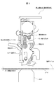
- FIG. 2 shows the overall configuration of the blocking mechanism 30 during normal trading.
- the card is transported in the card transport direction X1 (from right to left).
- the blocking mechanism 30 includes an actuator 31, a tension spring 32, a first blocking member 33, a link member 34, a second blocking member 35, a compression spring 36, a base 37, a cover member 39, and the like.
- the actuator 31 includes a movable iron core 311 that can be sucked, and sucks the movable iron core 311 when an abnormality is detected by the sensor.
- the suction direction is a direction from the front side to the back side.
- the actuator 31 does not suck the movable iron core 311 and the arm 38 connected to the movable iron core 311 does not move. Therefore, the state in which the groove 351 and the end 381 of the arm 38 are engaged is maintained. In this case, the second blocking member 35 is supported by the arm 38 in a state of being retracted from the card by a certain distance.
- the tension spring 32 is stretched between a tension member 101 formed on the bracket 100 (see FIG. 6) and a tension member 331 formed on the first blocking member 33.
- the tension spring 32 urges the tension member 331 in a direction to rotate the first blocking member 33 counterclockwise.
- the first blocking member 33 is The rotation is limited by the two blocking members 35, and is supported so as not to rotate by the pulling force of the tension spring 32.
- the first blocking member 33 is an eccentric cam whose distance from the rotation shaft 332 to the first uneven portion 333 is not uniform.
- the first blocking member 33 is formed with a blocking state release lever 334. In the present embodiment, it is possible to release the blocking state (FIGS. 4 and 5) and form the normal transaction state (FIGS. 2 and 3) simply by pressing the blocking state release lever 334. .
- the first blocking member 33 is supported by the second blocking member 35 with its rotation limited.
- the link member 34 has one end connected to the first blocking member 33 and the other end connected to the second blocking member 35, thereby connecting the first blocking member 33 and the second blocking member 35. , A member that operates the two together.
- the second blocking member 35 is an eccentric cam that includes a groove 351 and a second uneven portion 352, a rotation shaft 353, and a blade 354, and the distance from the rotation shaft 353 to the tip of the blade 354 is not uniform.
- the second blocking member 35 is supported by the arm 38 with its rotation limited by the arm 38 with the blade 354 retracted from the card by a certain distance.
- the second blocking member 35 supports the first blocking member 33 while restricting the rotation of the first blocking member 33.
- the compression spring 36 has one end connected to a part of the second blocking member 35 and the other end movably abutted against the wall 102 of the bracket 100 (see FIG. 6).
- the compression spring 36 biases the second blocking member 35 in a direction in which the second blocking member 35 is rotated counterclockwise.
- the second blocking member 35 is normally used during a transaction. Is supported by the arm 38 with its rotation restricted by a certain distance from the card.
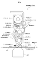
- FIG. 3 shows the overall configuration of the blocking mechanism 30 when the blocking mechanism 30 of FIG. 2 is viewed from the opposite direction (the back side of the paper). Accordingly, the card is transported in the card transport direction X1 (from left to right).
- the cover member 39, the tension spring 40, and the protrusion 335 will be particularly described.
- the cover member 39 is supported by the protrusion 335 in a state where the end portion is retracted from the card by a certain distance.
- the tension spring 40 is stretched between a protrusion 103 formed on the bracket 100 and a stretching member 391 formed on the cover member 39.
- the tension spring 40 biases the pulling force downward with respect to the cover member 39.
- the movement of the cover member 39 is restricted by the protrusion 335, and depending on the pulling force of the tension spring 40, the pulling force may be lowered. It is supported not to move.
- the protrusion 335 is a protrusion formed on the first blocking member 33 and supports the cover member 39 in a state where it is retracted from the card by a certain distance.
- the protrusion 335 moves up and down in conjunction with the operation of the first blocking member 33.
- the protrusion 335 moves upward.
- the projection 335 moves the cover member 39 upward against the pulling force of the tension spring 40.
- the protrusion 335 moves the cover member 39 upward in conjunction with the operation of the first blocking member 33 rotating counterclockwise simply by pressing the blocking state release lever 334. Can do.
- the second blocking member 35 is supported by the arm 38
- the first blocking member 33 is supported by the second blocking member 35.
- the cover member 39 can be supported and fixed by the protrusion 335 of the first blocking member 33.
- FIG. 4 shows the overall configuration of the blocking mechanism 30 in the blocking state.
- the card is transported along the card transport direction X1 (from right to left).
- the actuator 31 sucks the movable iron core 311 from the near side to the back of the page
- the arm 38 (see FIG. 6) connected to the movable iron core 311 moves.
- this blocking state (FIGS. 4 and 5) is formed.
- the tension spring 32 urges the tension member 331 in the direction of rotating the first blocking member 33 counterclockwise, and when the end 381 of the arm 38 is disengaged from the groove 351, The first blocking member 33 is rotated counterclockwise by the pulling force.
- the first blocking member 33 is urged by the tension spring 32 via the tension member 331, and when the end 381 of the arm 38 is disengaged from the groove 351, the first blocking member 33 is supported by the second blocking member 35. Is released and rotates counterclockwise about the rotation shaft 332 as an axis. And when the 1st uneven
- the first blocking member 33 is an eccentric cam whose distance from the rotation shaft 332 to the first uneven portion 333 is not uniform. Therefore, even when the second blocking member 35 rotates counterclockwise after the first uneven portion 333 contacts the second blocking member 35, the contact state can be maintained.
- the first uneven portion 333 When the first uneven portion 333 contacts the second blocking member 35, the first uneven portion 333 engages with the second uneven portion 352 formed at the end of the second blocking member 35.
- the second blocking member 35 is prevented from rotating clockwise. It does not prevent counterclockwise rotation.
- the first blocking member 33 is formed with a blocking state release lever 334.
- the blocking state release lever 334 When the blocking state release lever 334 is pressed in the release direction, the first blocking member 33 rotates clockwise about the rotation shaft 332 against the pulling force of the tension spring 32. After rotating clockwise, the rotation is limited and supported by the second blocking member 35. Then, a normal transaction state (FIGS. 2 and 3) is formed.
- the link member 34 does not act on the first blocking member 33 and the second blocking member 35 in the blocking state shown here, but the blocking state release lever 334 is pressed from the blocking state to the first blocking member 33.
- the blocking member 33 rotates clockwise
- the second blocking member 35 is rotated clockwise in conjunction with the rotation operation of the first blocking member 33.
- the predetermined position is a position where the end 381 of the arm 38 is disposed.
- the groove 351 and the end portion 381 of the arm 38 are engaged, and the second blocking member 35 is supported and fixed by the arm 38. As a result, the blocking state is released.
- the first blocking member 33 When the blocking state release lever 334 that has been pressed is released, the first blocking member 33 receives the pulling force of the tension spring 32 and rotates slightly counterclockwise about the rotation shaft 332. When the vicinity of the lower end of the first uneven portion 333 comes into contact with the vicinity of the upper end of the second uneven portion 352, the first blocking member 33 is supported by the second blocking member 35 and stops rotating. Thereby, the normal transaction state (FIGS. 2 and 3) before the abnormality is detected is formed.
- the second blocking member 35 When the end 381 of the arm 38 is disengaged from the groove 351, the second blocking member 35 receives a pressing force urged by the compression spring 36 and rotates counterclockwise about the rotation shaft 353. Then, when the blade 354 formed at the end portion contacts the card, the second blocking member 35 stops rotating and forms a blocking state.
- the second blocking member 35 is an eccentric cam whose distance from the rotating shaft 353 to the tip of the blade 354 is not uniform. Therefore, even when the second blocking member 35 rotates counterclockwise after the blade 354 contacts the card, the contact state can be maintained.
- the cover member 39 operates so as to contact the card in conjunction with the rotation operation of the first blocking member 33. Thereby, it is possible to prevent a card-shaped thin plate (for example, a shim plate) from being inserted between the blade 354 and the card, and it is possible to more firmly prevent the card from being illegally extracted.
- a card-shaped thin plate for example, a shim plate
- the compression spring 36 has one end connected to a part of the second blocking member 35 and the other end movably abutted against the wall 102 of the bracket 100 (see FIG. 6). As described above, the compression spring 36 biases the second blocking member 35 with a pressing force. When the end 381 of the arm 38 is disengaged from the groove 351, the pressing force causes the second blocking member 35. Rotate counterclockwise.
- FIG. 5 shows the overall configuration of the blocking mechanism 30 when the blocking mechanism 30 of FIG. 4 is viewed from the opposite direction (the back side of the paper). Therefore, the card is transported in the card transport direction X1 (from left to right).
- the cover member 39, the tension spring 40, and the protrusion 335 will be particularly described.
- the cover member 39 is released from the support by the protrusions 335, moves downward by the downward pulling force of the tension spring 40, and operates so that the tip abuts against the card.
- the tension spring 40 urges the cover member 39 downward to pull the cover member 39 released from the support by the protrusion 335 downward.
- the protrusion 335 moves up and down in conjunction with the operation of the first blocking member 33.
- the protrusion 335 moves downward.
- the tip of the cover member 39 comes into contact with the card.
- FIG. 6 is an exploded perspective view of the blocking mechanism 30.
- Each member constituting the blocking mechanism 30 is installed on the bracket 100.
- the bracket 100 is formed with protrusions, holes, and the like for installing each member, and each member is appropriately accommodated by installing each member at a predetermined location.
- the operation when the blocking state (FIGS. 4 and 5) after the abnormality is detected is formed together with the members from the normal state (FIGS. 2 and 3) before the abnormality is detected.
- the actuator 31 is fixed in advance to a predetermined position of the bracket 100 here, and an arm 38 is connected to the movable iron core 311 which is not shown here. While the arm 38 is connected to the movable core 311, in the normal state, the arm 38 supports the groove 351 with the end 381 and fixes the second blocking member 35 (FIGS. 2 and 3).
- the actuator 31 sucks the movable iron core 311.
- the movable iron core 311 is sucked, one end of the arm 38 connected to the movable iron core 311 is pulled in the sucking direction of the movable iron core 311 and rotates counterclockwise about the rotation shaft 382. Then, the end portion 381 of the arm 38 is disengaged from the groove 351, and the second blocking member 35 is not supported.
- the second blocking member 35 When the second blocking member 35 is not supported by the arm 38, the second blocking member 35 rotates counterclockwise by receiving a pressing force urged by a compression spring 36 not shown here, and the blade 354 moves on the table 37. Stops rotating when it touches the card. On the other hand, when the second blocking member 35 rotates, the first blocking member 33 is released from the contact state between the first uneven portion 333 and the second uneven portion 352 and is not supported.
- the first blocking member 33 When the first blocking member 33 is not supported by the second blocking member 35, the first blocking member 33 rotates counterclockwise by receiving the pulling force urged by the tension spring 32, and the first uneven portion 333 is second. Rotation is stopped when it comes into contact with the uneven portion 352.
- the projection 335 moves downward in conjunction with the operation of the first blocking member 33 rotating counterclockwise, and is not supported by the projection 335.
- the cover member 39 receives the downward pulling force of the tension spring 40 and moves downward, and stops moving when it contacts the card.
- the second blocking member 35 rotates clockwise because the first uneven portion 333 and the second uneven portion 352 are in contact with each other.
- the first blocking member 33 blocks this. Therefore, a blocking state is formed (FIGS. 4 and 5).
- the release operation in the case of releasing this blocking state only requires pressing the blocking state release lever 334 as described above.
- the blocking state release lever 334 is pressed, the first blocking member 33 rotates clockwise, the link member 34 transmits this rotation to the second blocking member 35, and the second blocking member 35 is also interlocked. Rotate clockwise. Further, the projection 335 moves upward in conjunction with the rotational movement of the first blocking member 33, and the cover member 39 rises against the pulling force of the tension spring 40 in conjunction with the upward movement of the projection 335. Move in the direction.
- the end 381 of the arm 38 is engaged with the groove, whereby the second blocking member 35 is supported and fixed by the arm 38.
- the second blocking member 35 is fixed, the first blocking member 33 is supported and fixed by the second blocking member 35.
- the cover member 39 supported by the protrusion 335 is also fixed.
- the first blocking member 33 and the second blocking member 35 are connected by the link member 34, and the first blocking member 33 is connected to the first blocking member 33.
- the second blocking member 35 is also rotated in conjunction with the rotation of the blocking member 33, and the cover member 39 is moved in the vertical direction in conjunction with the rotation of the first blocking member 33. Therefore, when releasing the blocking state, both the first blocking member 33 and the second blocking member 35 are rotated and the cover member 39 is moved upward by simply pressing the blocking state release lever 334. The blocking state can be released.
- the card can be firmly fixed in the blocking state, the entire apparatus can be downsized and the releasing operation can be simplified, and foreign matter can be prevented from being inserted between the blade 354 and the card.
Landscapes
- Physics & Mathematics (AREA)
- General Physics & Mathematics (AREA)
- Engineering & Computer Science (AREA)
- Theoretical Computer Science (AREA)
- Business, Economics & Management (AREA)
- Microelectronics & Electronic Packaging (AREA)
- Computer Networks & Wireless Communication (AREA)
- Accounting & Taxation (AREA)
- Strategic Management (AREA)
- General Business, Economics & Management (AREA)
- Conveying Record Carriers (AREA)
- Feeding Of Articles By Means Other Than Belts Or Rollers (AREA)
Abstract
Description
図1は、本実施の形態におけるカード処理装置1の全体構成を示す。カード処理装置1は、磁気カード又はICカードのような各種情報が記録されたカードが挿入口から挿入されると、カードを所定の位置まで搬送する。そして磁気ヘッド20又はIC接点ユニット(図示省略)を用いて、カードに予め記録されている情報を読み取り、またはカードに新たな情報を書き込む。
図2は、通常取引時における阻止機構30の全体構成を示す。カードはカード搬送方向X1(右から左)に搬送される。阻止機構30は、アクチュエータ31、引っ張りばね32、第1の阻止部材33、リンク部材34、第2の阻止部材35、圧縮ばね36、台37及びカバー部材39等を備えて構成される。
図4は、阻止状態時における阻止機構30の全体構成を示す。カードはカード搬送方向X1(右から左)に沿って搬送される。アクチュエータ31が可動鉄心311を紙面手前から奥方向に吸引すると、可動鉄心311に接続されているアーム38(図6参照)が可動する。アーム38の端部381が溝351から外れると、この阻止状態(図4及び図5)が形成される。
図6は、阻止機構30の分解斜視図である。阻止機構30を構成する各部材は、ブラケット100に設置される。ブラケット100には、各部材を設置するための突起や穴等が形成されており、各部材を所定の場所に設置することで各部材が適切に収容される。ここでは異常が検知される前の通常状態(図2、図3)から異常が検知された後の阻止状態(図4、図5)が形成される際の動作について、部材とともに説明する。
以上のように本実施の形態におけるカード処理装置1によれば、第1の阻止部材33と第2の阻止部材35とをリンク部材34により接続し、第1の阻止部材33の回転動作に連動させて第2の阻止部材35も回転動作させるようにし、合わせて第1の阻止部材33の回転動作に連動させてカバー部材39を上下方向に動作させるようにしたので、阻止状態を解除する際、阻止状態解除レバー334を押下するだけで、第1の阻止部材33及び第2の阻止部材35の両方を回転させるとともにカバー部材39を上方向に移動させて阻止状態を解除することができる。
10 搬送ローラ
20 磁気ヘッド
25 ヘッド対向ローラ
30 阻止機構
31 アクチュエータ
32 引っ張りばね
33 第1の阻止部材
34 リンク部材
35 第2の阻止部材
36 圧縮ばね
37 台
38 アーム
39 カバー部材
40 引っ張りばね
Claims (9)
- カードが抜き取られることを阻止する阻止機構を備えたカード処理装置において、
前記阻止機構は、
第1の阻止部材と、第2の阻止部材と、リンク部材と、カバー部材とを備え、
前記第1の阻止部材は、
阻止状態時に前記第2の阻止部材に係合して前記第2の阻止部材の回転動作を制限し、
阻止状態を解除する阻止状態解除レバーが押下されると、前記第2の阻止部材の回転動作の制限を解除するように動作し、
前記第2の阻止部材は、
阻止状態時に刃を前記カードに接触させた状態を維持し、
前記阻止状態解除レバーが押下されると、前記刃を前記カードに接触させた状態を解除するように回転動作し、
前記リンク部材は、
前記阻止状態解除レバーが押下されると、前記第1の阻止部材の動作に連動して前記第2の阻止部材が回転動作するように前記第1の阻止部材と前記第2の阻止部材とを接続し、
前記カバー部材は、
阻止状態時に端部を前記カードに当接させた状態を維持し、
前記阻止状態解除レバーが押下されると、前記第1の阻止部材の動作に連動して前記端部を前記カードに当接させた状態を解除するように動作する
ことを特徴とするカード処理装置。 - 前記第1の阻止部材は、
阻止状態時に端部に形成されている第1の凹凸部を前記第2の阻止部材の端部に形成されている第2の凹凸部に係合して前記第2の阻止部材の回転動作を制限する
ことを特徴とする請求項1に記載のカード処理装置。 - 前記第1の阻止部材は、
前記阻止状態解除レバーが押下されると、前記第1の凹凸部が前記第2の凹凸部から離れる方向に回転し、前記第1の凹凸部と前記第2の凹凸部との係合を解除して、前記第2の阻止部材の回転動作の制限を解除する
ことを特徴とする請求項2に記載のカード処理装置。 - 前記リンク部材は、
前記阻止状態解除レバーが押下されると、前記第1の阻止部材の回転動作に伴って移動し、所定距離だけ移動した後、前記第1の阻止部材の回転動作を前記第2の阻止部材に伝達して、前記第2の阻止部材を回転させる
ことを特徴とする請求項3に記載のカード処理装置。 - 前記第2の阻止部材は、
前記阻止状態解除レバーが押下されると、前記リンク部材を介して、前記第1の阻止部材の回転動作に連動して回転した後、支持部材により支持されて固定される
ことを特徴とする請求項4に記載のカード処理装置。 - 前記第1の阻止部材は、
前記阻止状態解除レバーが押下されて前記第2の阻止部材が固定された後、前記阻止状態解除レバーが押下されなくなると、前記第1の凹凸部が前記第2の凹凸部に近づく方向に回転し、前記第2の阻止部材に接触すると回転を停止する
ことを特徴とする請求項5に記載のカード処理装置。 - 前記第1の阻止部材は、
回転軸から前記第1の凹凸部までの間の距離が均一ではない偏心カムであり、
前記第2の阻止部材は、
回転軸から前記第2の凹凸部までの間の距離が均一ではない偏心カムである
ことを特徴とする請求項6に記載のカード処理装置。 - 前記カバー部材は、
引っ張りばねにより前記端部を前記カードに当接させる方向に力が付勢されており、
阻止状態時には前記第1の阻止部材に形成されている突起による支持が解除され、前記引っ張りばねの力により前記端部を前記カードに当接させた状態を維持し、
前記阻止状態解除レバーが押下されると、前記第1の阻止部材の動作に連動して前記突起が上方向に移動し、該突起の上方向の移動に連動して前記引っ張りばねの力に抗って上方向に移動する
ことを特徴とする請求項7に記載のカード処理装置。 - 前記1~8の何れか1項に記載のカード処理装置を備える
ことを特徴とする自動取引装置。
Priority Applications (3)
| Application Number | Priority Date | Filing Date | Title |
|---|---|---|---|
| JP2017511483A JP6302137B2 (ja) | 2015-04-10 | 2016-02-05 | カード処理装置及び自動取引装置 |
| KR1020177012830A KR101858979B1 (ko) | 2015-04-10 | 2016-02-05 | 카드 처리 장치 및 자동 거래 장치 |
| CN201680004084.3A CN107004144B (zh) | 2015-04-10 | 2016-02-05 | 卡处理装置及自动交易装置 |
Applications Claiming Priority (2)
| Application Number | Priority Date | Filing Date | Title |
|---|---|---|---|
| JP2015-080536 | 2015-04-10 | ||
| JP2015080536 | 2015-04-10 |
Publications (1)
| Publication Number | Publication Date |
|---|---|
| WO2016163143A1 true WO2016163143A1 (ja) | 2016-10-13 |
Family
ID=57072494
Family Applications (1)
| Application Number | Title | Priority Date | Filing Date |
|---|---|---|---|
| PCT/JP2016/053508 Ceased WO2016163143A1 (ja) | 2015-04-10 | 2016-02-05 | カード処理装置及び自動取引装置 |
Country Status (4)
| Country | Link |
|---|---|
| JP (1) | JP6302137B2 (ja) |
| KR (1) | KR101858979B1 (ja) |
| CN (1) | CN107004144B (ja) |
| WO (1) | WO2016163143A1 (ja) |
Citations (3)
| Publication number | Priority date | Publication date | Assignee | Title |
|---|---|---|---|---|
| JP2006155567A (ja) * | 2004-10-25 | 2006-06-15 | Nidec Sankyo Corp | カードリーダ |
| JP2013191037A (ja) * | 2012-03-14 | 2013-09-26 | Hitachi Omron Terminal Solutions Corp | 自動取引装置、及び自動取引装置のスキミング防止方法 |
| WO2015193935A1 (ja) * | 2014-06-16 | 2015-12-23 | 日立オムロンターミナルソリューションズ株式会社 | カード処理装置 |
Family Cites Families (8)
| Publication number | Priority date | Publication date | Assignee | Title |
|---|---|---|---|---|
| TW368198U (en) * | 1997-12-15 | 1999-08-21 | Hon Hai Prec Ind Co Ltd | Back card apparatus for electronic card |
| JP4223382B2 (ja) * | 2003-05-23 | 2009-02-12 | 日立オムロンターミナルソリューションズ株式会社 | カード処理装置 |
| US7175085B2 (en) * | 2003-12-17 | 2007-02-13 | Nidec Sankyo Corporation | Card reader |
| JP4163127B2 (ja) * | 2004-01-22 | 2008-10-08 | 日立オムロンターミナルソリューションズ株式会社 | 冊子取扱装置における改頁機構 |
| CN101174303B (zh) * | 2004-10-25 | 2010-06-16 | 日本电产三协株式会社 | 读卡器 |
| TWM266493U (en) * | 2004-10-26 | 2005-06-01 | Carry Computer Eng Co Ltd | Data access device for memory card |
| KR101079965B1 (ko) * | 2009-07-31 | 2011-11-04 | 엘지엔시스(주) | 매체카세트의 록킹장치 |
| JP5473973B2 (ja) * | 2011-03-24 | 2014-04-16 | 日立オムロンターミナルソリューションズ株式会社 | カード処理装置 |
-
2016
- 2016-02-05 CN CN201680004084.3A patent/CN107004144B/zh active Active
- 2016-02-05 JP JP2017511483A patent/JP6302137B2/ja active Active
- 2016-02-05 KR KR1020177012830A patent/KR101858979B1/ko active Active
- 2016-02-05 WO PCT/JP2016/053508 patent/WO2016163143A1/ja not_active Ceased
Patent Citations (3)
| Publication number | Priority date | Publication date | Assignee | Title |
|---|---|---|---|---|
| JP2006155567A (ja) * | 2004-10-25 | 2006-06-15 | Nidec Sankyo Corp | カードリーダ |
| JP2013191037A (ja) * | 2012-03-14 | 2013-09-26 | Hitachi Omron Terminal Solutions Corp | 自動取引装置、及び自動取引装置のスキミング防止方法 |
| WO2015193935A1 (ja) * | 2014-06-16 | 2015-12-23 | 日立オムロンターミナルソリューションズ株式会社 | カード処理装置 |
Also Published As
| Publication number | Publication date |
|---|---|
| KR20170073616A (ko) | 2017-06-28 |
| CN107004144A (zh) | 2017-08-01 |
| JPWO2016163143A1 (ja) | 2017-09-14 |
| CN107004144B (zh) | 2019-12-10 |
| KR101858979B1 (ko) | 2018-05-18 |
| JP6302137B2 (ja) | 2018-03-28 |
Similar Documents
| Publication | Publication Date | Title |
|---|---|---|
| JP3696468B2 (ja) | カードリーダ | |
| JP6189539B2 (ja) | カード処理装置 | |
| JP6302137B2 (ja) | カード処理装置及び自動取引装置 | |
| CN100407225C (zh) | 卡处理装置 | |
| JP6167234B2 (ja) | Ic接点ユニット及びicカード処理装置 | |
| CN103593921A (zh) | 自动交易装置及自动交易装置的卡资料套取防止方法 | |
| JP6506971B2 (ja) | カード処理装置 | |
| JP4346470B2 (ja) | カード処理装置 | |
| JP6287913B2 (ja) | カード・カセット装置 | |
| JP6449604B2 (ja) | カードリーダ | |
| JP6038470B2 (ja) | プリンタ装置 | |
| KR101909407B1 (ko) | Ic 접점 유닛, ic 카드 처리 장치 및 자동 거래 장치 | |
| WO2016009697A1 (ja) | 自動取引装置 | |
| JP4561316B2 (ja) | 紙幣処理装置 | |
| JP2015048156A (ja) | 媒体収納カセット、及び媒体発行装置 | |
| KR200384020Y1 (ko) | 통장프린터의 통장정렬장치 | |
| JP5850568B2 (ja) | カードリーダ | |
| TW202116653A (zh) | 紙張處理裝置 | |
| JP2019084805A (ja) | 媒体処理装置 | |
| JP2019095979A (ja) | 紙葉類取扱装置及び紙葉類取扱装置の制御方法 | |
| JP2003151009A (ja) | 通帳繰り出し機構 | |
| JP2012218828A (ja) | 媒体搬送機構 |
Legal Events
| Date | Code | Title | Description |
|---|---|---|---|
| 121 | Ep: the epo has been informed by wipo that ep was designated in this application |
Ref document number: 16776312 Country of ref document: EP Kind code of ref document: A1 |
|
| ENP | Entry into the national phase |
Ref document number: 20177012830 Country of ref document: KR Kind code of ref document: A |
|
| ENP | Entry into the national phase |
Ref document number: 2017511483 Country of ref document: JP Kind code of ref document: A |
|
| NENP | Non-entry into the national phase |
Ref country code: DE |
|
| 122 | Ep: pct application non-entry in european phase |
Ref document number: 16776312 Country of ref document: EP Kind code of ref document: A1 |