WO2016159128A1 - クレーンの情報提示システム - Google Patents
クレーンの情報提示システム Download PDFInfo
- Publication number
- WO2016159128A1 WO2016159128A1 PCT/JP2016/060475 JP2016060475W WO2016159128A1 WO 2016159128 A1 WO2016159128 A1 WO 2016159128A1 JP 2016060475 W JP2016060475 W JP 2016060475W WO 2016159128 A1 WO2016159128 A1 WO 2016159128A1
- Authority
- WO
- WIPO (PCT)
- Prior art keywords
- rope
- load
- information
- hoisting
- index value
- Prior art date
- Legal status (The legal status is an assumption and is not a legal conclusion. Google has not performed a legal analysis and makes no representation as to the accuracy of the status listed.)
- Ceased
Links
Images



Classifications
-
- B—PERFORMING OPERATIONS; TRANSPORTING
- B66—HOISTING; LIFTING; HAULING
- B66C—CRANES; LOAD-ENGAGING ELEMENTS OR DEVICES FOR CRANES, CAPSTANS, WINCHES, OR TACKLES
- B66C13/00—Other constructional features or details
- B66C13/16—Applications of indicating, registering, or weighing devices
-
- B—PERFORMING OPERATIONS; TRANSPORTING
- B66—HOISTING; LIFTING; HAULING
- B66C—CRANES; LOAD-ENGAGING ELEMENTS OR DEVICES FOR CRANES, CAPSTANS, WINCHES, OR TACKLES
- B66C13/00—Other constructional features or details
-
- B—PERFORMING OPERATIONS; TRANSPORTING
- B66—HOISTING; LIFTING; HAULING
- B66C—CRANES; LOAD-ENGAGING ELEMENTS OR DEVICES FOR CRANES, CAPSTANS, WINCHES, OR TACKLES
- B66C15/00—Safety gear
-
- B—PERFORMING OPERATIONS; TRANSPORTING
- B66—HOISTING; LIFTING; HAULING
- B66C—CRANES; LOAD-ENGAGING ELEMENTS OR DEVICES FOR CRANES, CAPSTANS, WINCHES, OR TACKLES
- B66C15/00—Safety gear
- B66C15/06—Arrangements or use of warning devices
- B66C15/065—Arrangements or use of warning devices electrical
-
- G—PHYSICS
- G07—CHECKING-DEVICES
- G07C—TIME OR ATTENDANCE REGISTERS; REGISTERING OR INDICATING THE WORKING OF MACHINES; GENERATING RANDOM NUMBERS; VOTING OR LOTTERY APPARATUS; ARRANGEMENTS, SYSTEMS OR APPARATUS FOR CHECKING NOT PROVIDED FOR ELSEWHERE
- G07C5/00—Registering or indicating the working of vehicles
- G07C5/08—Registering or indicating performance data other than driving, working, idle, or waiting time, with or without registering driving, working, idle or waiting time
- G07C5/0816—Indicating performance data, e.g. occurrence of a malfunction
- G07C5/0825—Indicating performance data, e.g. occurrence of a malfunction using optical means
Definitions
- the present invention relates to a crane information presentation system.
- the crane includes a hoisting winch for hoisting and lowering a suspended load and a hoisting winch for hoisting hoisting members such as a boom.
- the hoisting winch includes a drum on which a suspension rope that is a wire rope is wound, and the suspension rope is wound and unwound by rotating and rotating the drum. Further, the hoisting winch includes a drum around which a hoisting rope that is a wire rope is wound, and the hoisting member is hoisted by rotating and rotating the hoisting rope.
- an information presentation system that presents information about a wire rope of a winch of such a crane is known (see, for example, Patent Document 1 below).
- Patent Document 1 the amount of rotation of the drum of the hoisting winch of the crane is detected, the winding layer and the winding row of the rope remaining on the drum are derived from the detected amount of rotation, and the derived winding layer of the rope And the system which displays the number of winding rows on a display part is indicated.
- the wire rope fed out from the winch of the crane is loaded with the crane work. For example, a load resulting from a suspended load is applied to the hanging rope, and a load resulting from a tipping moment of the hoisting member to the front is applied to the hoisting rope. For this reason, fatigue is accumulated in the wire rope due to the load applied to it, and it becomes necessary to replace the wire rope.
- the present invention has been made to solve the above-mentioned problems, and its purpose is a guideline for judging the replacement timing of the wire rope from the viewpoint of accumulated fatigue of the wire rope used in the winch of the crane. It is to present information.
- the crane information presentation system in one aspect of the present invention, A system for presenting information about the wire rope of a crane with a winch that moves the object up and down by feeding and winding the wire rope, A load sensor for detecting a load applied to the wire rope; A load index derivation unit that derives a load index value that is an index value of a load applied to the wire rope at a predetermined period based on the load detected by the load sensor; By acquiring the load index value at the predetermined period, statistical information indicating a correspondence relationship between the load index value and the accumulated time when the load corresponding to the load index value is applied to the wire rope is created. An information processing device; A presentation unit that presents the statistical information created by the information processing apparatus.
- the present invention it is possible to present information that serves as a guideline for determining the replacement timing of a wire rope from the viewpoint of accumulated fatigue of the wire rope used in the winch of the crane.
- FIG. 4 is a view corresponding to FIG.
- the crane 2 (see FIG. 1) includes a self-propelled lower traveling body 40 and an upper revolving body 45 mounted on the lower traveling body 40 so as to be capable of turning about a vertical axis.
- the upper turning body 45 is provided with a working device 50 for carrying out crane work.
- This working device 50 includes a boom 51 as a hoisting member, a mast 52, a gantry 53, a mast side spreader 55, a gantry side spreader 56, a hoisting winch 61, a hoisting winch 62, a hook device 64, A suspension rope 66, a undulation rope 67, and a guy line 68 are provided.
- the boom 51 is attached to the front part of the upper swing body 45 so that it can be raised and lowered.
- a top sheave 51 a is provided at the tip of the boom 51.
- the mast 52 is provided at a position behind the boom 51 in the upper swing body 45.
- the mast 52 is provided so as to be rotatable with its lower end portion as a fulcrum.
- a mast side spreader 55 is provided at the upper end of the mast 52.
- the tip of the mast 52 is connected to the tip of the boom 51 via a guy line 68.
- the gantry 53 is erected at a position further rearward of the mast 52 in the upper swing body 45, that is, at the rear of the upper swing body 45.
- a gantry spreader 56 is provided at the upper end of the gantry 53.
- the hoisting winch 61 is an example of a winch in the present invention, and is mounted on the upper swing body 45.
- the hoisting winch 61 includes a hoisting drum 61a (an example of a drum) around which a suspension rope 66 that is a wire rope is wound.
- the suspension rope 66 drawn out from the hoisting drum 61 a extends to the tip of the boom 51, and suspends the hook device 64 from the tip of the boom 51.
- the hook device 64 suspends the suspended load 100.
- the hook device 64 includes an unillustrated hook sheave, and a suspension rope 66 is wound around the hook sheave and the top sheave 51a with a predetermined number of hooks.
- the hoisting winch 61 rotates the hoisting drum 61a to wind and unwind the hanging rope 66 to wind and lower the hook device 64 and the suspended load 100 hung thereon.
- the undulating winch 62 is another example of the winch in the present invention, and is provided at the lower part of the gantry 53.
- the hoisting winch 62 has a hoisting drum 62a (an example of a drum) around which a hoisting rope 67 that is a wire rope is wound.
- the hoisting rope 67 drawn out from the hoisting drum 62 a is wound around the sheave of the gantry side spreader 56 and the sheave of the mast side spreader 55.
- the hoisting winch 62 rotates the hoisting drum 62a and winds the hoisting rope 67 to draw the mast side spreader 55 toward the gantry side spreader 56, thereby rotating the mast 52 rearward and booming via the guy line 68.
- the boom 51 is erected by pulling the front end portion of the rear 51.
- the hoisting winch 62 allows the mast side spreader 55 to move forward from the gantry side spreader 56 by rotating the hoisting drum 62a and feeding the hoisting rope 67, whereby the mast 52 rotates forward.
- the boom 51 falls.
- the information presentation system 1 presents information that serves as a guideline for determining the replacement time for the hanging rope 66 and the hoisting rope 67 of the crane 2 as described above.
- FIG. 2 shows a schematic overall configuration of the information presentation system 1
- FIG. 3 shows a configuration of the information acquisition system 4 of the crane 2 constituting the information presentation system 1.
- the information presentation system 1 is configured to acquire and present information on a plurality of cranes 2. As shown in FIG. 2, the information presentation system 1 includes an information acquisition system 4 mounted on each crane 2, a mobile phone network 6, and a presentation unit 9.
- the information acquisition system 4 is a system for acquiring various information about the crane 2 on which it is mounted. As shown in FIG. 3, the information acquisition system 4 includes a detector group 18, an overload prevention device 19, a remaining winding amount deriving unit 20, an ECU (Engine Control Unit) 24, a data logger 28, a CAN- bus (Control Area Network bus) 30.
- the detector group 18 includes a plurality of detectors that detect values related to the operation of each operating unit of the crane 2. Specifically, the detector group 18 includes a proximity sensor 41 (an example of a rotation amount sensor) that detects the rotation amount of the hoisting drum 61a, and a proximity sensor 42 (a rotation amount sensor of the rotation amount sensor) that detects the rotation amount of the undulation drum 62a. An example), a load cell 43 (an example of a load sensor) that detects a load applied to the hoisting drum 61a, a load cell 44 (an example of a load sensor) that detects a load applied to the hoisting drum 62a, and the like are included.
- the proximity sensor 41 is provided in the vicinity of the hoisting drum 61a.
- a plurality of protrusions arranged in the circumferential direction of the peripheral edge portion are provided on the peripheral edge portion of the end surface in the axial direction of the hoisting drum 61a over the entire periphery of the peripheral edge portion. It arrange
- the proximity sensor 41 detects each protrusion passing through a position close to the proximity sensor 41 as the hoisting drum 61a rotates, and outputs a pulse signal corresponding to the number of the detected protuberances of the hoisting drum 61a. Output as a detection signal indicating the amount of rotation.
- the proximity sensor 42 is provided in the vicinity of the undulation drum 62 a and is configured in the same manner as the proximity sensor 41. That is, the undulating drum 62a is provided with a plurality of protrusions as in the hoisting drum 61a, and the proximity sensor 42 passes through positions close to the proximity sensor 42 as the undulating drum 62a rotates. The protrusions are detected, and a pulse signal corresponding to the detected number of protrusions is output as a detection signal indicating the amount of rotation of the undulation drum 62a.
- the overload prevention device 19 is a device for preventing the load applied to the work device 50 from being overloaded during crane work.
- the overload prevention device 19 calculates the actual load applied to the hanging rope 66 based on the detection value of the load cell 43 that detects the load applied to the hoisting drum 61a. Further, the overload prevention device 19 calculates the actual load applied to the hoisting rope 67 based on the detection value of the load cell 44 that detects the load applied to the hoisting drum 62a. Then, the overload prevention device 19 calculates a load factor for the suspension rope 66 that is a ratio of the calculated actual load to the rated load of the suspension rope 66 based on the calculated actual load applied to the suspension rope 66.
- the overload prevention device 19 calculates a load factor for the hoisting rope 67 that is a ratio of the calculated actual load to the rated load of the hoisting rope 67 based on the calculated actual load applied to the hoisting rope 67.
- the load factor for the hanging rope 66 and the hoisting rope 67 corresponds to an index value of the load applied to the hanging rope 66 and the hoisting rope 67, and is an example of the load index value in the present invention.
- the overload prevention device 19 for calculating the load factor is an example of a load index deriving unit in the present invention.
- the overload prevention device 19 determines that an overload condition has occurred when the calculated load factor for the suspended rope 66 or the calculated load factor for the hoisting rope 67 is 105% or more, and operates the crane 2. Stop. When the overload prevention device 19 determines that an overload condition has occurred, the overload prevention apparatus 19 allows the operation state of the crane 2 at that time to be grasped later so that the work state of the crane 2 at the time when the overload condition has occurred can be grasped later. Various data including the state are stored in a memory (not shown) of the overload prevention device 19.
- overload prevention device 19 determines that an overload condition has occurred, the date, time, boom angle of the boom 51, rated load, actual load, work radius, load factor, Input / output signals of main controllers 21 and 22 (described later), operation signals for operation levers for operating hoisting winch 61, hoisting winch 62 and other operating parts of crane 2 are stored in the memory of overload prevention device 19. save.
- the overload prevention device 19 determines that an overload condition has occurred, the overload prevention device 19 transmits the same data as the data stored in the memory to the data logger 28.
- the winding remaining amount deriving unit 20 includes a remaining amount of the suspension rope 66 wound on the winding drum 61 a of the winding winch 61 (hereinafter referred to as a winding remaining amount of the suspension rope 66), and a lifting drum 62 a of the lifting winch 62.
- the remaining amount of the hoisting rope 67 wound around (hereinafter referred to as the remaining amount of hoisting rope 67) is derived.
- the winding remaining amount deriving unit 20 is an example of a feeding length index deriving unit according to the present invention, and the remaining winding amounts of the suspension rope 66 and the hoisting rope 67 derived by the remaining winding amount deriving unit 20 are the feeding length in the present invention.
- the remaining winding amount deriving unit 20 includes a first main controller 21 and a second main controller 22.
- 1st and 2nd main controller 22 controls each operation part to which the crane 2 respond
- the first main controller 21 receives a pulse signal indicating the rotation amount of the hoisting drum 61a from the proximity sensor 41.
- the first main controller 21 calculates the remaining winding amount of the hanging rope 66 wound around the hoisting drum 61a at that time based on the input pulse signal. That is, the first main controller 21 has a function as a device for deriving the remaining winding amount of the hanging rope 66.
- the first main controller 21 calculates the rotation amount of the hoisting drum 61a from the input pulse signal.
- the first main controller 21 incorporates in advance conversion information indicating the correlation between the amount of rotation of the hoisting drum 61a and the winding layer and winding row of the suspension rope 66 wound around the hoisting drum 61a. .
- the first main controller 21 derives the winding layer and the winding row of the hanging rope 66 corresponding to the calculated rotation amount of the hoisting drum 61a based on the conversion information.
- the first main controller 21 determines the remaining amount of the suspension rope 66, that is, the length of the suspension rope 66 that remains on the winding drum 61a, based on the winding layer and the winding line of the suspension rope 66 that has been derived. Is calculated.
- the second main controller 22 receives a pulse signal indicating the amount of rotation of the hoisting drum 62a from the proximity sensor 42.
- the second main controller 22 calculates the remaining winding amount of the hoisting rope 67 wound around the hoisting drum 62a at that time based on the input pulse signal. That is, the second main controller 22 has a function as a device for deriving the remaining winding amount of the hoisting rope 67.
- the second main controller 22 calculates the rotation amount of the undulation drum 62a from the input pulse signal.
- the second main controller 22 incorporates conversion information indicating the correlation between the amount of rotation of the hoisting drum 62a and the winding layer and winding row of the hoisting rope 67 wound around the hoisting drum 62a.
- the second main controller 22 derives the winding layer and the winding row of the hoisting rope 67 corresponding to the calculated rotation amount of the hoisting drum 62 a based on the conversion information incorporated in the second main controller 22.
- the second main controller 22 determines the remaining winding amount of the hoisting rope 67, that is, the length of the hoisting rope 67 remaining on the hoisting drum 62a, based on the winding layer and winding row of the derived hoisting rope 67. calculate.
- the ECU 24 controls the engine speed of the crane 2.
- the CAN-bus 30 connects the first and second main controllers 21 and 22, the ECU 24, the overload prevention device 19, and the data logger 28 so that data can be transferred between them. .
- the CAN-bus 30 is simply referred to as a bus 30.
- the first main controller 21 outputs the calculated remaining amount data of the hanging rope 66 to the bus 30 at a predetermined cycle.
- the second main controller 22 outputs the calculated data of the remaining winding amount of the hoisting rope 67 to the bus 30 at a predetermined cycle.
- the overload prevention device 19 outputs the rated load, actual load, and load factor data of the hanging rope 66 and the hoisting rope 67 to the bus 30 at a predetermined cycle.
- the data logger 28 is a device that acquires data stored in the bus 30 from the bus 30 and stores it.
- the data logger 28 has an information processing device 31.
- the information processing device 31 includes load factor data for the hanging rope 66, load factor data for the hoisting rope 67, remaining winding data for the hanging rope 66, and remaining winding data for the hoisting rope 67, Data on the operation of the crane 2 (operation information) is acquired from the bus 30 and stored. And in this embodiment, while the information processing apparatus 31 creates the suspension rope statistical information indicating the correspondence between the load factor and the remaining winding amount and the accumulated time for the suspension rope 66 based on each acquired data, The hoisting rope statistical information indicating the correspondence between the load factor and the remaining amount of winding for the hoisting rope 67 and the accumulated time is created.
- the accumulated time in the suspended rope statistical information is an elapsed time in a state in which a load corresponding to a certain load factor is applied to the suspended rope 66 and a suspended rope 66 with a certain remaining amount is wound around the hoisting drum 61a. Equivalent to.
- the accumulated time in the hoisting rope statistical information is the elapsed time in a state in which a load corresponding to a certain load factor is applied to the hoisting rope 67 and the hoisting rope 67 with a certain remaining winding amount is wound around the hoisting drum 62a. It corresponds to.
- the suspended rope statistical information and the undulating rope statistical information are examples of load payout length statistical information in the present invention.
- the configuration of the information processing apparatus 31 will be described in detail.
- the information processing apparatus 31 includes an information processing unit 32 and a nonvolatile memory 34.
- the information processing unit 32 processes each data acquired from the bus 30.
- the nonvolatile memory 34 stores and accumulates information and data processed by the information processing unit 32.
- the information processing unit 32 acquires load factor data for the hanging rope 66 and the hoisting rope 67 from the bus 30 at a predetermined cycle. In addition, the information processing unit 32 acquires the remaining winding data of the hanging rope 66 and the hoisting rope 67 from the bus 30 at the same predetermined cycle as that for acquiring the load factor data.
- the information processing unit 32 counts up the time each time the load factor and winding remaining amount data for the hanging rope 66 and the hoisting rope 67 are acquired. And the information processing part 32 acquires the load factor data about the acquired suspension rope 66, the data of the winding remaining amount of the suspension rope 66 acquired at the same timing as the acquisition of the data of the load factor, and acquisition of those data Accordingly, the accumulated time data obtained by counting up the time is associated with each other and stored in the nonvolatile memory 34. In addition, the information processing unit 32 acquires the load factor data about the acquired hoisting rope 67, the remaining amount data of the hoisting rope 67 acquired at the same timing as the acquisition of the load factor data, and the acquisition of the data. Accordingly, the accumulated time data obtained by counting up the time is associated with each other and stored in the nonvolatile memory 34.
- the information processing unit 32 classifies the load factor and the remaining winding amount of the hanging rope 66 into a plurality of categories, and associates each category of the load factor with each category of the remaining winding amount.
- the data of the accumulated time t is stored in the nonvolatile memory 34 in the form of the following statistical table.
- the load factor x for the hanging rope 66 is classified as 0% to less than 20%, 20% to less than 40%, 40% to less than 60%, and 60% to less than 80%. And 80% to 100%. Further, the winding remaining amount y of the hanging rope 66 is classified into a number of sections for each predetermined length of the hanging rope 66.
- the information processing unit 32 identifies the classification of the load factor x corresponding to the acquired load factor data for the hanging rope 66 and the classification of the remaining winding amount y corresponding to the calculated remaining winding rope 66 data.
- One cell in the above statistical table corresponding to both the specified load factor x and the remaining volume y (the row of the specified load factor x and the specified column of the remaining volume y)
- the data of the accumulated time t is registered in the cell at the intersection).
- the information processing unit 32 performs such registration and accumulates the data.
- Suspension rope statistical information indicating the correspondence with the accumulated time is created.
- the suspended rope statistical information indicates the distribution of the accumulated time for each section of the load factor and the remaining winding amount for the suspended rope 66, and is included in the concept of accumulated time distribution data in the present invention.
- the information processing unit 32 stores the created suspended rope statistical information in the nonvolatile memory 34.
- the information processing unit 32 accumulates data for the hoisting rope 67 in the same manner as for the hanging rope 66, thereby showing the correspondence between the load factor and the remaining amount of winding for the hoisting rope 67 and the accumulated time. Create statistical information.
- This hoisting rope statistical information indicates the distribution of the accumulated time for each section of the load factor and the remaining winding amount for the hoisting rope 67, and is included in the concept of the accumulated time distribution data in the present invention.
- the information processing unit 32 stores the created undulation rope statistical information in the nonvolatile memory 34.
- the information processing unit 32 receives the data transmitted from the overload prevention device 19 to the data logger 28 when an overload condition occurs, and stores it in the nonvolatile memory 34.
- the information processing unit 32 transmits the suspended rope statistical information, the hoisting rope statistical information, the crane 2 position information, and the crane 2 operation information stored in the nonvolatile memory 34 through the mobile phone network 6 to be described later of the presentation unit 9 (see FIG. 2). To the information storage server 10. The information processing unit 32 transmits this information by transmitting period data in which information stored in the nonvolatile memory 34 is collected for a predetermined period set in advance.
- the presenting unit 9 presents the suspended rope statistical information, the hoisting rope statistical information, the position information of the crane 2, and the operation information transmitted from the information processing unit 32. That is, the presentation unit 9 presents the period data transmitted from the information processing unit 32. As shown in FIG. 2, the presenting unit 9 includes an information storage server 10 and a stored information browsing terminal 14.
- the information storage server 10 stores and stores the information received from the information processing unit 32 of the data logger 28 (see FIG. 3) of each crane 2 for each crane 2.
- the information storage server 10 processes the period data of the received suspension rope statistical information, and creates distribution map data indicating the distribution of the accumulated time for each section of the load factor and the remaining winding amount for the suspension rope 66. Further, the information accumulation server 10 processes the received period data of the hoisting rope statistical information, and creates distribution map data indicating the distribution of the accumulated time of each section of the load factor and the remaining amount of winding for the hoisting rope 67. .
- the information storage server 10 stores distribution map data for the created hanging rope 66 and hoisting rope 67.
- the stored information browsing terminal 14 is a terminal that can access the information storage server 10 via the Internet line 12.
- a personal computer is used as the stored information browsing terminal 14.
- the stored information browsing terminal 14 can display information and data stored in the information storage server 10 and is an example of a display unit in the present invention. That is, the stored information browsing terminal 14 can browse information and data stored in the information storage server 10.
- FIG. 4 and FIG. 5 show an example of a distribution diagram for the suspension rope 66 created from the suspension rope statistical information and displayed on the stored information browsing terminal 14.
- FIG. 4 is a distribution diagram in the case where the crane work is performed in a state where the extending length of the hanging rope 66 is relatively small, that is, in a state where the remaining amount of the hanging rope 66 in the hoisting winch 61 is relatively large.
- FIG. 5 is a distribution diagram in a case where the crane work is performed in a state where the extending length of the hanging rope 66 is relatively large, that is, in a state where the remaining amount of the hanging rope 66 in the hoisting winch 61 is relatively small. 4 and 5 indicate the remaining amount of the suspension rope 66 in the hoisting winch 61, and the remaining amount of the suspension rope 66 increases from L1 to L10.
- the remaining amount of the suspension rope 66 is within a relatively large range (L8 or more range).
- L8 or more range When the crane operation is performed in a state in which the accumulated time of the suspension rope 66 is large and the feeding length of the suspension rope 66 is relatively large, as shown in FIG.
- the accumulated time in the range of L2 to L4 is large. That is, depending on whether the crane work is an operation performed in a state where the extending length of the hanging rope 66 is relatively small or an operation performed in a state where the extending length of the hanging rope 66 is relatively large, the winding of the hanging rope 66 is performed. A difference occurs in the distribution of the accumulated time with respect to the remaining amount.
- the hanging rope 66 It is suggested that there is a large bias in the use site.
- the bias of the use part of the suspension rope 66 is large, there is a possibility that fatigue is accumulated in a limited part of the suspension rope 66 (the suspension rope 66 is locally damaged). There is a possibility that the replacement time will be earlier.
- the accumulated time is distributed in the distribution map and the distribution map shows a gentle aspect, the use parts of the hanging rope 66 are dispersed, and locally on a specific part of the hanging rope 66. This suggests that fatigue is unlikely to accumulate.
- the distribution map obtained from the suspension rope statistical information is a guideline for determining the replacement time of the suspension rope 66.
- a distribution map having the same form as the distribution map obtained from the hanging rope statistical information can be obtained, and the obtained distribution chart is used as a guideline for determining the replacement time of the hoisting rope 67. Become.
- step S1 the engine key of the crane 2 is turned on (step S1).
- the data logger 28 performs the previous data restoration process by the information processing unit 32 (step S2). Specifically, in the nonvolatile memory 34 of the data logger 28, various data during the previous operation are stored in the nonvolatile memory 34 at the end of the previous operation of the crane 2 (when the previous engine key is turned off).
- the information processing unit 32 reads and restores the last data stored in the nonvolatile memory 34 in response to the current engine key being turned on. More specifically, the information processing unit 32 reads out and restores the suspended rope statistical information and the undulating rope statistical information in the previous last data stored in the nonvolatile memory 34.
- step S3 a data acquisition cycle by the data logger 28 is started.
- the data logger 28 receives various data flowing in the bus 30 (step S4).
- the information processing unit 32 extracts target data for creating the suspended rope statistical information and the undulating rope statistical information from the data received by the data logger 28 (step S5). Specifically, the information processing unit 32 takes out load factor data for the hanging rope 66 and the hoisting rope 67 and data on the remaining amount of the hoisting rope 66 and the hoisting rope 67 as target data.
- the information processing unit 32 analyzes the acquired load factor data for the hanging rope 66 and the hoisting rope 67 and the data on the remaining amount of the hoisting rope 66 and the hoisting rope 67 (step S6). Specifically, the information processing unit 32 specifies a category corresponding to the load factor of the acquired suspension rope 66 among the plurality of categories of the load factor of the suspension rope statistical information restored in step S2, and the suspension rope. Among the plurality of categories of the remaining amount of statistical information, the category corresponding to the acquired remaining amount of the suspended rope 66 is specified.
- the information processing unit 32 specifies the category corresponding to the load factor for the acquired undulation rope 67 among the plurality of categories of the load factor of the undulation rope statistical information restored in step S2, and the undulation rope statistical information. Among the plurality of categories of the remaining winding amount, the category corresponding to the acquired winding amount of the hoisting rope 67 is specified.
- the information processing unit 32 sets the time corresponding to both the specified load factor category and the specified remaining winding amount category in the suspended rope statistical information to the data acquisition cycle by the information processing unit 32 (predetermined cycle: 1 sec).
- the time corresponding to both the specified load factor category and the specified remaining winding volume category in the undulation rope statistical information is counted as the time corresponding to the data acquisition period. Counts up only (step S7).
- the information processing section 32 stores the new suspended rope statistical information and the new undulating rope statistical information after counting up time in the nonvolatile memory 34 (step S8). That is, the information processing unit 32 updates the suspended rope statistical information and the undulating rope statistical information stored in the nonvolatile memory 34 to the new suspended rope statistic information and the new undulating rope statistical information after counting up the time. .
- the information processing section 32 determines whether or not the engine key has been turned off (step S9). If it is determined that the engine key has not been turned off, the data acquisition cycle after step S4 is repeated. Execute. On the other hand, if the information processing unit 32 determines that the engine key has been turned off, the information processing unit 32 performs processing for storing the suspended rope statistical information and the undulating rope statistical information of the nonvolatile memory 34 updated in step S8 (step S10). The processing in the data logger 28 ends.
- the suspended rope statistical information and the undulating rope statistical information in the nonvolatile memory 34 are updated to the suspended rope statistical information and the undulating rope statistical information stored in step S10 each time the engine key is turned off. Further, every time the engine key is turned off, the information processing unit 32 performs processing for storing the operation information of the crane 2 accumulated in the nonvolatile memory 34 until that time.
- the information processing unit 32 collects the suspension rope statistical information and the hoisting rope statistical information and the crane 2 operation information stored in the nonvolatile memory 34 for a predetermined period set in advance. And the created period data is transmitted to the information storage server 10 through the cellular phone network 6.
- the load factor and the remaining winding amount of the suspension rope 66 and the load corresponding to the load factor are applied to the suspension rope 66 and the suspension rope 66 having a length corresponding to the remaining winding amount is the hoisting drum 61a.
- Suspended rope statistical information showing the correspondence with the accumulated time in the state of being wound around is presented by the presentation unit 9. Further, the load factor and the remaining winding amount of the hoisting rope 67 and a load corresponding to the load factor are applied to the hoisting rope 67, and the hoisting rope 67 having a length corresponding to the remaining winding amount is wound around the hoisting drum 62a.
- the hoisting rope statistical information indicating the correspondence with the accumulated time in the remaining state is presented by the presentation unit 9.
- the suspended rope statistical information includes a state in which the length of the suspended rope 66 is wound around the hoisting drum 61a, that is, a state in which the length of the suspended rope 66 is extended from the hoisting drum 61a. Since it indicates how much load is applied to the hanging rope 66 and how much accumulated time it takes, this hanging rope statistical information is a guideline for judging the replacement time of the hanging rope 66 from the viewpoint of accumulated fatigue. Further, the hoisting rope statistical information indicates a state in which the hoisting rope 67 remains on the hoisting drum 62a, that is, a state in which the hoisting rope 67 is drawn out from the hoisting drum 62a.
- the hoisting rope statistical information is a guideline for determining the replacement time of the hoisting rope 67 from the viewpoint of accumulated fatigue. Therefore, in the present embodiment, it is possible to present information that serves as a guideline for determining the replacement time of the suspension rope 66 and the undulation rope 67 from the viewpoint of accumulated fatigue of the suspension rope 66 and the undulation rope 67.
- the suspended rope statistical information indicates the distribution of the accumulated time of each section of the load factor and the remaining winding amount for the suspended rope 66
- the undulating rope statistical information includes the load factor and the winding amount for the undulating rope 67.
- the distribution of the accumulated time for each category of the remaining amount is shown. That is, the accumulated time indicating how long the suspended rope 66 is wound around the hoisting drum 61a and the accumulated time when the suspended rope 66 is loaded is large.
- the distribution can be presented by the suspended rope statistical information, and how long the hoisting rope 67 is wound around the hoisting drum 62a and how much load is applied to the hoisting rope 67.
- the distribution of accumulated time indicating whether the accumulated time is large can be presented by the undulating rope statistical information.
- the information storage server 10 calculates the distribution of the accumulated time of each category of the load factor and the remaining amount of winding for the hanging rope 66 and the hoisting rope 67 based on the hoisting rope statistical information and the hoisting rope statistical information.
- the distribution map data shown is created, and the stored information browsing terminal 14 displays the distribution maps for the hanging rope 66 and the hoisting rope 67 based on the distribution map data created by the information storage server 10. For this reason, it is possible to visually grasp the correlation between the degree of load applied to the hanging rope 66 and the hoisting rope 67, the remaining amount of winding of the hanging rope 66 and the hoisting rope 67, and the accumulated time.
- a portion of the hanging rope 66 and the hoisting rope 67 that are under load can be specified with practical practicality without using a new measuring device or the like, and the position of the crane 2 depends on the posture of the crane 2. It is possible to present suspended rope statistical information and undulating rope statistical information.
- the hoisting drum 61a of the hoisting winch 61 and the hoisting winch 62, and the hoisting drum The amount of the suspension rope 66 and the undulation rope 67 wound around the 62a is a value generally measured by various methods, and the total length of the suspension rope 66 and the undulation rope 67 is a known value.
- the length of the portion of the suspension rope 66 and the undulation rope 67 that is fed from the hoisting drum 61a and the undulation drum 62a is the remaining amount of the suspension rope 66 and the undulation rope 67 in the hoisting drum 61a and the undulation drum 62a. It can be seen from For this reason, although the very local part itself which is loaded among the hanging rope 66 and the hoisting rope 67 cannot be grasped based on the value of the remaining amount of winding, the hoisting rope 66 and the hoisting rope are loaded. It is possible to grasp which part of the entire area 67 is.
- the remaining amount of the hoisting rope 66 and the hoisting rope 67 in the hoisting drum 61a and the hoisting drum 62a is derived as the feed length index value, so that the hoisting rope 66 is not used separately. , A portion of the hoisting rope 67 that is loaded can be identified with realistic practicality. Further, since the remaining amount of the hoisting rope 66 and the hoisting rope 67 in the hoisting drum 61a and the hoisting drum 62a is a value that does not depend on the posture of the crane 2, etc., in this embodiment, this remaining hoisting amount is used as the feed length index value. As a result, it is possible to present suspended rope statistical information and undulating rope statistical information that are not influenced by the posture of the crane 2 or the like.
- the remaining data of the hoisting rope 66 and the hoisting rope 67 may be omitted from the hoisting rope statistical information and the hoisting rope statistical information.
- the suspension rope statistical information and the undulation rope statistical information correspond to the relationship between the load factor for the suspension rope 66 and the undulation rope 67 and the accumulated time that the load corresponding to the load factor is applied to the suspension rope 66 and the undulation rope 67. It may indicate only.
- the information processing unit 32 of the data logger 28 acquires information on the state of the working device 50 and information on the working posture of the crane 2 when the operation of the crane 2 is stopped, that is, when the engine is stopped, and stores the information in the nonvolatile memory 34. At the same time, the stored information may be transmitted to the presentation unit 9. In this case, the presentation unit 9 presents the received information on the state of the work device 50 and the work posture of the crane 2 when the operation of the crane 2 is stopped.
- the hanging rope 66 and the hoisting rope 67 are held at a fixed position without moving, but the hoisting rope fed out from the corresponding hoisting drum 61a and the hoisting drum 62a. 66, a predetermined portion of the hoisting rope 67 is burdened.
- the suspension rope 66 is held at a fixed position in a portion corresponding to the winding opening of the hoisting drum 61a, a portion bent along the top sheave 51a, a portion bent along the hook sheave, or the like. Even if it is in a state, there is a burden.
- the hoisting rope 67 has a hoisting rope 67 at a portion of the hoisting rope 67 corresponding to the winding opening of the hoisting drum 62a, a portion bent along the sheave of the gantry spreader 56, a portion bent along the sheave of the mast side spreader 55, and the like. Even if it is held at a certain position, a load is applied.
- the parts of the hanging rope 66 and the hoisting rope 67 that are burdened when the operation of the crane 2 is stopped differ depending on the state of the work device 50 when the operation of the crane 2 is stopped and the work posture of the crane 2.
- the state of the working device 50 when the crane 2 is stopped and the information on the working posture of the crane 2 presented by the presentation unit 9 as described above are borne by the hanging rope 66 and the hoisting rope 67 while the crane 2 is stopped. It is information that suggests the part where the mark is applied.
- the information processing part 32 of the data logger 28 produces hanging rope statistical information and undulation rope statistical information
- the information storage server 10 is based on the statistical information created by the information processing part 32.
- the cumulative time distribution data for 66 and the cumulative time distribution data for the hoisting rope 67 are created, but the information processing configuration according to the present invention is not necessarily limited to such a configuration.
- the information processing unit 32 acquires the load factor and winding amount data for the hanging rope 66 and the hoisting rope 67, creates the hoisting rope statistical information and the hoisting rope statistical information, and the hoisting rope 66 and the hoisting rope 67. All of the data of the accumulated time distribution map may be created. In this case, the information processing unit 32 transmits the data of the accumulated time distribution map for the created hanging rope 66 and undulating rope 67 to the information storage server 10 of the presentation unit 9. Then, the information accumulation server 10 may accumulate and store the received distribution map data so that the stored distribution map data can be viewed on the stored information browsing terminal 14.
- the information processing unit 32 creates a distribution map corresponding to the data on the operation panel provided in the crane 2 based on the data of the distribution chart of the accumulated time for the created suspension rope 66 and the hoisting rope 67. It may be displayed.
- the crane information browsing terminal 36 is connected to the nonvolatile memory 34 of the data logger 28 via a communication line 37 such as USB (Universal Serial Bus), and the suspended rope statistics stored in the nonvolatile memory 34.
- the information and the undulating rope statistical information may be copied to the crane information browsing terminal 36.
- a personal computer is used as the crane information browsing terminal 36.
- the copied statistical information may be analyzed by application software in the crane information browsing terminal 36 to generate data of a cumulative time distribution map for the hanging rope 66 and the hoisting rope 67.
- the distribution map created by the crane information browsing terminal 36 can be browsed by the crane information browsing terminal 36.
- the crane information browsing terminal 36 is included in the concept of the presentation unit according to the present invention.
- the suspended rope statistical information and the undulation currently stored in the nonvolatile memory 34 are not waited for the period data of the suspended rope statistical information and the undulating rope statistical information to be transmitted to the information storage server 10.
- a distribution map (see, for example, FIG. 8) of the hanging rope 66 and the hoisting rope 67 created from the rope statistical information can be viewed on the crane information browsing terminal 36.
- a storage medium such as a USB memory may be used as means for copying the suspended rope statistical information and the undulating rope statistical information from the nonvolatile memory 34 to the crane information browsing terminal 36.
- the information processing unit 32 of the data logger 28 may transmit the acquired load factor and remaining winding data for the hanging rope 66 and the hoisting rope 67 to the information storage server 10 of the presentation unit 9 without analyzing the data.
- the information storage server 10 creates the suspension rope statistical information and the undulation rope statistical information based on the received load factor and winding amount data for the suspended rope 66 and the undulation rope 67, and from the created statistical information. You may make it produce the data of the distribution map of the accumulation time about the hanging rope 66 and the hoisting rope 67.
- FIG. In this case, the information storage server 10 is included in the concept of the information processing apparatus in the present invention.
- the stored information browsing terminal 14 may create the distribution map data. That is, the suspended rope statistical information and the undulating rope statistical information are downloaded from the information accumulation server 10 to the accumulated information browsing terminal 14, and the downloaded statistical information is analyzed by the application software at the accumulated information browsing terminal 14, and the suspended rope 66 and the undulating rope are analyzed. You may create the data of the distribution map of the accumulation time about the rope 67. FIG.
- the communication network used for transmitting data from the data logger 28 (information processing unit 32) to the information storage server 10 is not necessarily limited to the mobile phone network 6.
- a LAN Local Area Network
- other communication network may be used.
- the information processing unit 32 creates load information indicating the accumulated time when the heavy load state occurs for each of the extended lengths of the hanging rope 66 and the hoisting rope 67 and stores the load information in the nonvolatile memory 34, and the suspended rope statistical information and This load information may be transmitted to the information storage server 10 in addition to the undulation rope statistical information. Then, the information storage server 10 may create data of a load distribution diagram as shown in FIG. 9 from the received load information and allow the created load distribution diagram to be viewed on the stored information browsing terminal 14.
- the heavy load state is a state in which the load factor is 80% or more and 100% or less, and the information processing unit 32 is 80% or more of the suspended rope statistical information and the undulating rope statistical information.
- the load information is created by extracting the data of the correspondence relationship between the cumulative time of the load factor classification of% or less and the winding amount of the hanging rope 66 and the hoisting rope 67.
- the information processing unit 32 counts the number of occurrences of a heavy load state, that is, the number of times the acquired load factor is 80% or more and 100% or less, and counts the duration of each heavy load state, Data on the number of occurrences of the large load state and the duration of each large load state obtained thereby is added to the load information.
- the load information acquired by the information processing unit 32 is stored in the nonvolatile memory 34 of the data logger 28 and is transmitted to the information storage server 10.
- the information storage server 10 creates data of a load distribution diagram (see FIG. 9) based on the received load information.
- the load distribution chart is a graph in which the accumulated time when the heavy load state occurs in each section of the remaining amount of winding of the suspension rope 66 and the hoisting rope 67 is shown by a bar, and the accumulated time bar of each section of the remaining amount of winding is shown in the bar.
- An identification display (color coding, etc.) indicating the number of occurrences of a heavy load state is attached, and the length of each occurrence of the identified display in the vertical axis (cumulative time axis) direction is the continuation of the heavy load state of the occurrence time It represents time.
- the viewer can grasp how long it took a large load on the hanging rope 66 and the hoisting rope 67 and the number of times the large load was applied. And the duration of each load.
- the information processing unit 32 of the data logger 28 or the stored information browsing terminal 14 may create load distribution map data.
- the crane 2 may be provided with a notification unit that performs notification for encouraging the inspection of the hanging rope 66 and the hoisting rope 67 based on the hoisting rope statistical information and the hoisting rope statistical information.
- the crane 2 may include a display monitor that displays a message prompting the operator to check the hanging rope 66 and the hoisting rope 67 as an informing unit.
- the information processing unit 32 of the data logger 28 calculates the usage time of the hanging rope 66 by adding up the accumulated time of the hanging rope statistical information for each work posture in which the crane 2 has a different hanging ability. When the used time exceeds the specified time, a message prompting the inspection of the hanging rope 66 may be displayed on the display monitor.
- the information processing unit 32 similarly calculates the usage time of the hoisting rope 67 from the hoisting rope statistical information, and checks the hoisting rope 67 on the display monitor when the calculated usage time exceeds the specified time. A message prompting you may be displayed.
- a buzzer that emits a sound that prompts the operator to check the hanging rope 66 and the hoisting rope 67
- the crane 2 includes a measuring device that measures the diameters of the hanging rope 66 and the hoisting rope 67
- the information processing unit 32 of the data logger 28 has data on the diameters of the hanging rope 66 and the hoisting rope 67 measured by the measuring device. May be acquired and stored in the nonvolatile memory 34.
- the information processing unit 32 transmits the diameter data of the hanging rope 66 and the hoisting rope 67 accumulated in the nonvolatile memory 34 to the presenting unit 9, and the presenting unit 9 receives the received data of the diameter of the hoisting rope 66 and the hoisting rope 67. It may be presented together with the suspended rope statistical information and the undulating rope statistical information.
- the diameters of the suspension rope 66 and the undulation rope 67 are changed over time. Can present change information.
- the wire rope stretches as its load increases, and its diameter decreases. In addition, when fatigue is accumulated in the wire rope and the strand breaks, the diameter of the wire rope decreases.
- the information on the change over time of the diameters of the hanging rope 66 and the hoisting rope 67 serves as a guideline for replacing the hanging rope 66 and the hoisting rope 67, and this information is presented in addition to the hoisting rope statistical information and the hoisting rope statistical information.
- exchange time of the suspension rope 66 and the hoisting rope 67 more accurately can be shown.
- load index values according to the present invention, actual loads applied to the hanging rope 66 and the hoisting rope 67 may be used instead of the load factor.
- weighting for fatigue of the suspended rope 66 and the undulating rope 67 may be set for each cell of the accumulated time. That is, the condition of the remaining amount of winding that the hanging rope 66 and the hoisting rope 67 are painful is derived from the past maintenance information of the hanging rope 66 and the hoisting rope 67, and belongs to the category of the remaining amount of easy winding based on the derived condition. It is sufficient to increase the weighting of the cells, and to decrease the weighting of the cells belonging to the volume remaining volume category that is relatively painless. Moreover, the weight of the cell of the division should just be enlarged, so that it becomes a division with a large load factor.
- the center of the cumulative time distribution is derived, and the dispersion of the load factor in the axial direction and the dispersion of the winding remaining amount in the axial direction are calculated.
- the characteristic amount is derived during a period in which a crane work is performed using a wire rope as the hanging rope 66. After that, when the wire rope is replaced and another wire rope is used as the hanging rope 66 and the crane work is performed, the feature amount is similarly derived, and the derived feature amount is derived from the wire rope before the replacement. If it is equal to the amount, it is suggested that the usage of the suspended rope 66 after the replacement is the same as the usage of the wire rope before the replacement. The same applies to the hoisting rope 67.
- the feeding length of the hanging rope 66 from the hoisting winch 61 may be derived based on the remaining amount of the hoisting rope 66 in the hoisting winch 61, and the derived feeding length may be used as the feeding length index value according to the present invention.
- the feeding length of the hoisting rope 67 from the hoisting winch 62 may be derived based on the winding remaining amount of the hoisting rope 67 in the hoisting winch 62, and the derived feeding length may be used as the feeding length index value according to the present invention.
- a feeding length calculation unit is provided in the data logger 28, and the winding length of the suspension rope 66 calculated by the first main controller 21 from the total length of the suspension rope 66 registered in advance by the feeding length calculation unit is obtained. You may calculate the feeding length of the suspension rope 66 by subtracting. Further, the payout length calculating unit may calculate the payout length of the hoisting rope 67 by subtracting the remaining amount of the hoisting rope 67 calculated by the second main controller 22 from the total length of the hoisting rope 67 registered in advance. .
- the data logger 28 may not be provided with a feeding length calculation unit, and the first main controller 21 may calculate the feeding length of the hanging rope 66 and the second main controller 22 may calculate the feeding length of the hoisting rope 67. Then, using the calculated length of the suspended rope 66 and the hoisting rope 67 in place of the remaining amount of the hoisting rope 66 and the hoisting rope 67, the above statistical information, accumulated time distribution data, distribution map, etc. are created. May be presented. This embodiment can be summarized as follows.
- the crane information presentation system is a system for presenting information about the wire rope of the crane including a winch that moves the object up and down by feeding and winding the wire rope, A load index derivation unit that derives a load index value that is an index value of a load applied to the wire rope at a predetermined period; By acquiring the load index value at the predetermined period, statistical information indicating a correspondence relationship between the load index value and the accumulated time when the load corresponding to the load index value is applied to the wire rope is created.
- An information processing device A presentation unit that presents the statistical information created by the information processing apparatus.
- this crane information presentation system statistical information indicating the correspondence between the load index value, which is an index value of the load applied to the wire rope, and the accumulated time when the load corresponding to the load index value is applied to the wire rope is provided. Presented by the presentation unit. Therefore, based on the presented statistical information, it is possible to grasp how much load is applied to the wire rope and how much accumulated time it takes. Therefore, according to this information presentation system, it is possible to present information serving as a guideline for determining the replacement timing of the wire rope from the viewpoint of accumulated fatigue of the wire rope used in the winch of the crane.
- a feed length index deriving unit for deriving a feed length index value that is an index value of the length of the wire rope fed from the winch at the predetermined period;
- the information processing apparatus acquires the load index value and the feed length index value at the predetermined period, so that the load index is supplied to the wire rope that is fed at a length corresponding to the feed length index value.
- a load payout length statistical information indicating a correspondence relationship between a cumulative time in a state where a load corresponding to a value is applied, the load index value, and the feed length index value is created as the statistical information; It is preferable that the presenting unit presents the load payout length statistical information created by the information processing apparatus.
- the load payout length statistical information indicating the correspondence relationship between the load index value, the feed length index value, and the accumulated time is presented by the presentation unit. That is, based on the load payout length statistical information presented by the presenter, it is possible to determine how much wire rope has been drawn from the winch and how much load has been applied to the wire rope for how long. Can show.
- the information processing apparatus classifies the load index value and the feeding length index value into a plurality of sections, calculates the accumulated time corresponding to each section, and distributes the accumulated time in each section. It is preferable to create the accumulated time distribution data indicating the load delivery length statistical information.
- the accumulated time distribution data indicating the accumulated time distribution of each section of the load index value and the feed length index value
- the accumulated time distribution data can be presented by the presenting unit. That is, it is possible to present cumulative time distribution data representing how long the wire rope is extended from the winch and how much load is applied when the wire rope is loaded.
- the presenting unit includes a display unit that displays the cumulative time distribution of each section indicated by the cumulative time distribution data created by the information processing apparatus.
- the feeding length index deriving unit derives a winding remaining amount that is a length of the wire rope remaining in the winch as the feeding length index value.
- the portion of the wire rope that is under load can be identified with realistic practicality without using a separate new measuring device, etc., and the load feeding length statistical information that is not affected by the crane posture or the like can be obtained.
- the amount of the wire rope wound around the winch is generally measured by various methods.
- the total length of the wire rope is a known value. Therefore, the length of the portion of the wire rope that is fed out from the winch is a value that can be determined from the remaining winding amount of the wire rope in the winch.
- the portion of the wire rope that is loaded can be realized without using a separate measuring instrument or the like. Can be identified by practical utility.
- the winding remaining amount of the wire rope in the winch is a value that does not depend on the crane's posture or the like, in this configuration, the load that does not depend on the crane's posture or the like is obtained by deriving this winding remaining amount as the feed length index value.
- the payout length statistical information can be presented.
Landscapes
- Engineering & Computer Science (AREA)
- Mechanical Engineering (AREA)
- Physics & Mathematics (AREA)
- General Physics & Mathematics (AREA)
- Control And Safety Of Cranes (AREA)
Abstract
情報提示システムは、ロープにかかる負荷の指標値である負荷率を導出する過負荷防止装置と、過負荷防止装置によって導出された負荷率のデータとその導出された負荷率に対応する負荷がロープにかかった状態の時間の長さのデータとを互いに対応付けて蓄積し、各ロープについての負荷率と累積時間との対応関係を示す吊ロープ統計情報及び起伏ロープ統計情報を作成するデータロガーと、データロガーにより作成された吊ロープ統計情報及び起伏ロープ統計情報を提示する提示部と、を備える。
Description
本発明は、クレーンの情報提示システムに関する。
クレーンは、吊荷の巻き上げ及び巻き下げを行うための巻上ウインチと、ブーム等の起伏部材を起伏させるための起伏ウインチとを備えている。巻上ウインチは、ワイヤロープである吊ロープが巻かれたドラムを備えており、そのドラムを回転させて吊ロープの巻き取り及び繰り出しを行うことにより吊荷の巻き上げ及び巻き下げを行う。また、起伏ウインチは、ワイヤロープである起伏ロープが巻かれたドラムを備えており、そのドラムを回転させて起伏ロープの巻き取り及び繰り出しを行うことにより起伏部材を起伏させる。従来、このようなクレーンのウインチのワイヤロープについての情報を提示する情報提示システムが知られている(例えば、下記特許文献1参照)。
下記特許文献1には、クレーンの巻上ウインチのドラムの回転量を検出するとともにその検出した回転量からドラムに残っているロープの巻層及び巻列を導出し、その導出したロープの巻層及び巻列の数を表示部に表示するシステムが開示されている。
クレーンのウインチから繰り出されるワイヤロープには、クレーン作業に伴って負荷がかかる。例えば、吊ロープには、吊荷重に起因する負荷がかかり、起伏ロープには、起伏部材の前方への転倒モーメントに起因する負荷がかかる。このため、ワイヤロープにはそれにかかる負荷により疲労が蓄積し、いずれワイヤロープを交換する必要が生じる。
従来、クレーンのウインチのロープについての情報を提示するシステムとして上記のようにドラムにおけるロープの残巻の巻層数及び巻列数を表示部に表示するシステムが提案されているが、ワイヤロープの交換時期を判断するための指針となる情報を提示するシステムは存在しない。このため、一般的には、ワイヤロープをウインチドラムに装着してからの経過時間やクレーンの稼働時間が規定の時間に達したら一律にワイヤロープの交換時期が来たと判断したり、ワイヤロープ全体の状態及びそのワイヤロープを構成する素線の状態を目視で確認して交換時期を判断したりしている。
しかしながら、これらの一般的に行われている判断方法では、ワイヤロープにかかった負荷の履歴による蓄積疲労の観点からワイヤロープの交換時期を判断するための指針がない。このため、実際には交換を要するほどワイヤロープに疲労が蓄積されていないにもかかわらず、早期にワイヤロープが交換されてコストが増大している場合がある。
本発明は、上記の課題を解決するためになされたものであり、その目的は、クレーンのウインチで用いられるワイヤロープの蓄積疲労の観点からそのワイヤロープの交換時期を判断するための指針となる情報を提示することである。
本発明の一態様におけるクレーンの情報提示システムは、
ワイヤロープの繰り出し及び巻き取りを行って対象物を上下に動作させるウインチを備えたクレーンの前記ワイヤロープについての情報を提示するシステムであって、
前記ワイヤロープにかかる負荷を検出する負荷センサと、
前記負荷センサが検出した負荷に基づいて、前記ワイヤロープにかかる負荷の指標値である負荷指標値を所定周期で導出する負荷指標導出部と、
前記負荷指標値を前記所定周期で取得することで、前記負荷指標値に対応する負荷が前記ワイヤロープにかかった状態の累積時間と、前記負荷指標値との対応関係を示す統計情報を作成する情報処理装置と、
前記情報処理装置により作成された前記統計情報を提示する提示部と、を備える。
ワイヤロープの繰り出し及び巻き取りを行って対象物を上下に動作させるウインチを備えたクレーンの前記ワイヤロープについての情報を提示するシステムであって、
前記ワイヤロープにかかる負荷を検出する負荷センサと、
前記負荷センサが検出した負荷に基づいて、前記ワイヤロープにかかる負荷の指標値である負荷指標値を所定周期で導出する負荷指標導出部と、
前記負荷指標値を前記所定周期で取得することで、前記負荷指標値に対応する負荷が前記ワイヤロープにかかった状態の累積時間と、前記負荷指標値との対応関係を示す統計情報を作成する情報処理装置と、
前記情報処理装置により作成された前記統計情報を提示する提示部と、を備える。
本発明によれば、クレーンのウインチで用いられるワイヤロープの蓄積疲労の観点からそのワイヤロープの交換時期を判断するための指針となる情報を提示することができる。
以下、本発明の実施形態について図面を参照して説明する。
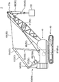
まず、図1を参照して、発明の一実施形態による情報提示システム1で情報を提示する対象となるクレーン2について説明する。
クレーン2(図1参照)は、自走可能な下部走行体40と、その下部走行体40上に縦軸回りに旋回可能となるように搭載された上部旋回体45とを備える。
上部旋回体45には、クレーン作業を行うための作業装置50が設けられている。この作業装置50は、起伏部材としてのブーム51と、マスト52と、ガントリ53と、マスト側スプレッダ55と、ガントリ側スプレッダ56と、巻上ウインチ61と、起伏ウインチ62と、フック装置64と、吊ロープ66と、起伏ロープ67と、ガイライン68と、を有する。
ブーム51は、起伏可能となるように上部旋回体45の前部に取り付けられている。ブーム51の先端にはトップシーブ51aが設けられている。
マスト52は、上部旋回体45においてブーム51の後方の位置に設けられている。マスト52は、その下端部を支点として回動可能となるように設けられている。このマスト52の上端部にマスト側スプレッダ55が設けられている。また、マスト52の先端は、ガイライン68を介してブーム51の先端部に接続されている。
ガントリ53は、上部旋回体45においてマスト52のさらに後方の位置、すなわち上部旋回体45の後部に立設されている。このガントリ53の上端部にガントリ側スプレッダ56が設けられている。
巻上ウインチ61は、本発明におけるウインチの一例であり、上部旋回体45に搭載されている。巻上ウインチ61は、ワイヤロープである吊ロープ66が巻かれた巻上ドラム61a(ドラムの一例)を有する。巻上ドラム61aから引き出された吊ロープ66は、ブーム51の先端へ延び、そのブーム51の先端からフック装置64を吊り下げる。フック装置64は、吊荷100を吊るものである。フック装置64は図略のフックシーブを備えており、このフックシーブとトップシーブ51aとに吊ロープ66が所定の掛数で巻き掛けられている。
巻上ウインチ61は、巻上ドラム61aを回転させて吊ロープ66の巻き取り及び繰り出しを行うことによりフック装置64及びそれに吊られた吊荷100の巻き上げ及び巻き下げを行う。
起伏ウインチ62は、本発明におけるウインチの別の一例であり、ガントリ53の下部に設けられている。起伏ウインチ62は、ワイヤロープである起伏ロープ67が巻かれた起伏ドラム62a(ドラムの一例)を有する。起伏ドラム62aから引き出された起伏ロープ67は、ガントリ側スプレッダ56のシーブとマスト側スプレッダ55のシーブとに掛け回されている。起伏ウインチ62は、起伏ドラム62aを回転させて起伏ロープ67を巻き取ることによりマスト側スプレッダ55をガントリ側スプレッダ56側へ引き寄せ、それによってマスト52を後方へ回動させるとともにガイライン68を介してブーム51の先端部を後方へ引っ張ってブーム51を起立させる。また、起伏ウインチ62は、起伏ドラム62aを回転させて起伏ロープ67を繰り出すことによりマスト側スプレッダ55がガントリ側スプレッダ56から前方へ離反することを許容し、それによってマスト52が前方へ回動しつつブーム51が倒伏するようになっている。
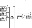
本実施形態による情報提示システム1は、以上のようなクレーン2の吊ロープ66及び起伏ロープ67についての交換時期の判断の指針となる情報を提示するものである。図2には、この情報提示システム1の概略的な全体構成が示されており、図3には、情報提示システム1を構成するクレーン2の情報取得システム4の構成が示されている。
情報提示システム1は、複数のクレーン2についての情報を取得して提示し得るように構成されている。情報提示システム1は、図2に示すように、各クレーン2に搭載された情報取得システム4と、携帯電話網6と、提示部9と、を備える。
情報取得システム4は、それが搭載されたクレーン2についての各種情報を取得するためのシステムである。情報取得システム4は、図3に示すように、検出器群18と、過負荷防止装置19と、巻残量導出部20と、ECU(Engine Control Unit)24と、データロガー28と、CAN-bus(Control Area Network bus)30と、を備える。
検出器群18は、クレーン2の各作動部の動作に関する値を検出する複数の検出器からなる。具体的には、検出器群18には、巻上ドラム61aの回転量を検出する近接センサ41(回転量センサの一例)、起伏ドラム62aの回転量を検出する近接センサ42(回転量センサの一例)、巻上ドラム61aにかかる負荷を検出するロードセル43(負荷センサの一例)、及び、起伏ドラム62aにかかる負荷を検出するロードセル44(負荷センサの一例)等が含まれる。
近接センサ41は、巻上ドラム61aの近傍に設けられている。巻上ドラム61aの軸方向の端面の周縁部には、その周縁部の周方向に並ぶ複数の突起部が当該周縁部の全周に亘って設けられており、近接センサ41は、その突起部に対向するように配置されている。近接センサ41は、巻上ドラム61aの回転に伴って当該近接センサ41に近接した位置を通過する各突起部を検知し、その検知した突起部の数に応じたパルス信号を巻上ドラム61aの回転量を示す検出信号として出力する。
また、近接センサ42は、起伏ドラム62aの近傍に設けられており、近接センサ41と同様に構成されている。すなわち、起伏ドラム62aには、巻上ドラム61aの場合と同様に複数の突起部が設けられ、近接センサ42は、起伏ドラム62aの回転に伴って当該近接センサ42に近接した位置を通過する各突起部を検知し、その検知した突起部の数に応じたパルス信号を起伏ドラム62aの回転量を示す検出信号として出力する。
過負荷防止装置19は、クレーン作業中に作業装置50にかかる負荷が過負荷状態になるのを防止するための装置である。過負荷防止装置19は、巻上ドラム61aにかかる負荷を検出するロードセル43の検出値に基づいて吊ロープ66にかかる実荷重を算出する。また、過負荷防止装置19は、起伏ドラム62aにかかる負荷を検出するロードセル44の検出値に基づいて起伏ロープ67にかかる実荷重を算出する。そして、過負荷防止装置19は、算出した吊ロープ66にかかる実荷重に基づいて、吊ロープ66の定格荷重に対する算出した実荷重の比率である吊ロープ66についての負荷率を算出する。また、過負荷防止装置19は、算出した起伏ロープ67にかかる実荷重に基づいて、起伏ロープ67の定格荷重に対する算出した実荷重の比率である起伏ロープ67についての負荷率を算出する。吊ロープ66,起伏ロープ67についての負荷率は、吊ロープ66,起伏ロープ67にかかる負荷の指標値に相当するものであり、本発明における負荷指標値の一例である。また、この負荷率を算出する過負荷防止装置19は、本発明における負荷指標導出部の一例である。
過負荷防止装置19は、算出した吊ロープ66についての負荷率又は算出した起伏ロープ67についての負荷率が105%以上になった場合に過負荷状態が発生したと判断してクレーン2の稼働を停止させる。過負荷防止装置19は、過負荷状態が発生したと判断した場合には、その過負荷状態が発生した時点のクレーン2の作業状態を後に把握できるようにするため、その時点のクレーン2の作業状態を含む各種データを当該過負荷防止装置19の図略のメモリに保存する。具体的には、過負荷防止装置19は、過負荷状態が発生したと判断した場合には、その時点における日付、時刻、ブーム51の起伏角度、定格荷重、実荷重、作業半径、負荷率、メインコントローラ21,22(後述)の入出力信号、巻上ウインチ61,起伏ウインチ62やその他のクレーン2の作動部を操作するための操作レバーの操作信号などを当該過負荷防止装置19のメモリに保存する。また、過負荷防止装置19は、過負荷状態が発生したと判断した場合には、そのメモリに保存したデータと同じデータをデータロガー28へ送信する。
巻残量導出部20は、巻上ウインチ61の巻上ドラム61aに巻かれている吊ロープ66の残量(以下、吊ロープ66の巻残量と称する)と、起伏ウインチ62の起伏ドラム62aに巻かれている起伏ロープ67の残量(以下、起伏ロープ67の巻残量と称する)とを導出する。巻残量導出部20は、本発明による繰出長指標導出部の一例であり、この巻残量導出部20によって導出される吊ロープ66,起伏ロープ67の巻残量は、本発明における繰出長指標値の一例である。吊ロープ66,起伏ロープ67の巻残量が多い場合には巻上ウインチ61,起伏ウインチ62からの吊ロープ66,起伏ロープ67の繰出長が少なくなり、吊ロープ66,起伏ロープ67の巻残量が少ない場合には巻上ウインチ61,起伏ウインチ62からの吊ロープ66,起伏ロープ67の繰出長が多くなるため、吊ロープ66,起伏ロープ67の巻残量は、巻上ウインチ61,起伏ウインチ62から繰り出された吊ロープ66,起伏ロープ67の長さの指標値である繰出長指標値として用いることができる。巻残量導出部20は、第1メインコントローラ21と、第2メインコントローラ22と、を含む。
第1及び第2メインコントローラ22は、それぞれ、クレーン2の対応する各作動部の制御を行う。具体的に、第1メインコントローラ21は、巻上ウインチ61の動作の制御を行い、第2メインコントローラ22は、起伏ウインチ62の動作の制御を行う。
第1メインコントローラ21には、近接センサ41から巻上ドラム61aの回転量を示すパルス信号が入力される。第1メインコントローラ21は、入力されたパルス信号に基づいてその時点で巻上ドラム61aに巻かれている吊ロープ66の巻残量を算出する。すなわち、第1メインコントローラ21は、吊ロープ66の巻残量の導出装置としての機能を有する。
具体的に、第1メインコントローラ21は、入力されたパルス信号から巻上ドラム61aの回転量を算出する。また、第1メインコントローラ21には、巻上ドラム61aの回転量と巻上ドラム61aに巻かれている吊ロープ66の巻層及び巻列との相関関係を示す換算情報が予め組み込まれている。第1メインコントローラ21は、算出した巻上ドラム61aの回転量に対応する吊ロープ66の巻層及び巻列を換算情報に基づいて導出する。そして、第1メインコントローラ21は、導出した吊ロープ66の巻層及び巻列に基づいて、吊ロープ66の巻残量、すなわち巻上ドラム61aに巻かれて残っている吊ロープ66の長さを算出する。
第2メインコントローラ22には、近接センサ42から起伏ドラム62aの回転量を示すパルス信号が入力される。第2メインコントローラ22は、入力されたパルス信号に基づいてその時点で起伏ドラム62aに巻かれている起伏ロープ67の巻残量を算出する。すなわち、第2メインコントローラ22は、起伏ロープ67の巻残量の導出装置としての機能を有する。
具体的に、第2メインコントローラ22は、入力されたパルス信号から起伏ドラム62aの回転量を算出する。また、第2メインコントローラ22には、起伏ドラム62aの回転量と起伏ドラム62aに巻かれている起伏ロープ67の巻層及び巻列との相関関係を示す換算情報が予め組み込まれている。第2メインコントローラ22は、算出した起伏ドラム62aの回転量に対応する起伏ロープ67の巻層及び巻列を当該第2メインコントローラ22に組み込まれた換算情報に基づいて導出する。そして、第2メインコントローラ22は、導出した起伏ロープ67の巻層及び巻列に基づいて、起伏ロープ67の巻残量、すなわち起伏ドラム62aに巻かれて残っている起伏ロープ67の長さを算出する。
ECU24は、クレーン2のエンジンの回転数を制御するものである。
CAN-bus30は、第1及び第2メインコントローラ21,22と、ECU24と、過負荷防止装置19と、データロガー28とをそれらの間でデータが転送可能となるように相互に接続している。以下、CAN-bus30のことを単にbus30と称する。第1メインコントローラ21は、算出した吊ロープ66の巻残量のデータをbus30へ所定周期で出力する。第2メインコントローラ22は、算出した起伏ロープ67の巻残量のデータをbus30へ所定周期で出力する。また、過負荷防止装置19は、吊ロープ66,起伏ロープ67についての定格荷重、実荷重及び負荷率のデータをbus30へ所定周期で出力する。
データロガー28は、bus30に流れるデータをそのbus30から取得して蓄積する装置である。データロガー28は、情報処理装置31を有する。
情報処理装置31は、吊ロープ66についての負荷率のデータと、起伏ロープ67についての負荷率のデータと、吊ロープ66の巻残量のデータと、起伏ロープ67の巻残量のデータと、クレーン2の稼働に関するデータ(稼働情報)とをbus30から取得して蓄積する。そして、本実施形態では、情報処理装置31が、取得した各データに基づいて、吊ロープ66についての負荷率及び巻残量と累積時間との対応関係を示す吊ロープ統計情報を作成するとともに、起伏ロープ67についての負荷率及び巻残量と累積時間との対応関係を示す起伏ロープ統計情報を作成する。
吊ロープ統計情報における累積時間は、ある負荷率に対応する負荷が吊ロープ66にかかるとともに、ある巻残量の吊ロープ66が巻上ドラム61aに巻かれて残っている状態での経過時間に相当する。また、起伏ロープ統計情報における累積時間は、ある負荷率に対応する負荷が起伏ロープ67にかかるとともに、ある巻残量の起伏ロープ67が起伏ドラム62aに巻かれて残っている状態での経過時間に相当する。吊ロープ統計情報及び起伏ロープ統計情報は、本発明における負荷繰出長統計情報の一例である。以下、情報処理装置31の構成について詳述する。
情報処理装置31は、情報処理部32と、不揮発メモリ34とを有する。情報処理部32は、bus30から取得した各データの処理を行うものである。また、不揮発メモリ34は、情報処理部32によって処理された情報及びデータを保存して蓄積するものである。
具体的に、情報処理部32は、吊ロープ66及び起伏ロープ67についての負荷率のデータをbus30から所定周期で取得する。また、情報処理部32は、吊ロープ66及び起伏ロープ67の巻残量のデータを、負荷率のデータを取得するのと同じ所定周期でbus30から取得する。
情報処理部32は、吊ロープ66,起伏ロープ67についての負荷率及び巻残量の各データを取得する毎に、時間をカウントアップする。そして、情報処理部32は、取得した吊ロープ66についての負荷率のデータと、その負荷率のデータの取得と同じタイミングで取得した吊ロープ66の巻残量のデータと、それらのデータの取得に応じて時間をカウントアップして得た累積時間のデータとを互いに対応付けて不揮発メモリ34に記憶させる。また、情報処理部32は、取得した起伏ロープ67についての負荷率のデータと、その負荷率のデータの取得と同じタイミングで取得した起伏ロープ67の巻残量のデータと、それらのデータの取得に応じて時間をカウントアップして得た累積時間のデータとを互いに対応付けて不揮発メモリ34に記憶させる。
具体的には、情報処理部32は、吊ロープ66についての負荷率と巻残量とをそれぞれ複数の区分に分類し、その負荷率の各区分と巻残量の各区分とを対応付けた下記の統計表の形態で累積時間tのデータを不揮発メモリ34に記憶させる。

本実施形態では、吊ロープ66についての負荷率xを、0%以上20%未満の区分、20%以上40%未満の区分、40%以上60%未満の区分、60%以上80%未満の区分、及び、80%以上100%以下の区分に分類している。また、吊ロープ66の巻残量yを吊ロープ66の所定長さ毎の多数の区分に分類している。情報処理部32は、取得した吊ロープ66についての負荷率のデータが該当する負荷率xの区分と、算出した吊ロープ66の巻残量のデータが該当する巻残量yの区分とを特定し、その特定した負荷率x及び巻残量yの両区分に対応する上記統計表中の1つのセル(特定した負荷率xの区分の横列と特定した巻残量yの区分の縦列とが交わった箇所のセル)に累積時間tのデータを登録する。情報処理部32は、吊ロープ66についての負荷率及び巻残量のデータを取得する毎にこのような登録を行ってデータを蓄積し、それによって吊ロープ66についての負荷率及び巻残量と累積時間との対応関係を示す吊ロープ統計情報を作成する。吊ロープ統計情報は、吊ロープ66についての負荷率及び巻残量の各区分毎の累積時間の分布を示し、本発明における累積時間分布データの概念に含まれる。情報処理部32は、作成した吊ロープ統計情報を不揮発メモリ34に保存する。
また、情報処理部32は、起伏ロープ67について、吊ロープ66の場合と同様にデータを蓄積し、それによって起伏ロープ67についての負荷率及び巻残量と累積時間との対応関係を示す起伏ロープ統計情報を作成する。この起伏ロープ統計情報は、起伏ロープ67についての負荷率及び巻残量の各区分毎の累積時間の分布を示し、本発明における累積時間分布データの概念に含まれる。情報処理部32は、作成した起伏ロープ統計情報を不揮発メモリ34に保存する。
また、情報処理部32は、過負荷状態が発生したときに過負荷防止装置19からデータロガー28に送信されたデータを受信して不揮発メモリ34に保存する。
情報処理部32は、不揮発メモリ34に保存された吊ロープ統計情報、起伏ロープ統計情報、クレーン2の位置情報及びクレーン2の稼働情報を携帯電話網6を通じて提示部9(図2参照)の後述の情報蓄積サーバ10へ送信する。情報処理部32は、この情報の送信を、予め設定された所定の期間で不揮発メモリ34に保存されている情報をまとめた期間データを送信することによって行う。
提示部9は、情報処理部32から送信された吊ロープ統計情報、起伏ロープ統計情報、クレーン2の位置情報及び稼働情報を提示するものである。すなわち、提示部9は、情報処理部32から送信された期間データを提示する。この提示部9は、図2に示すように、情報蓄積サーバ10及び蓄積情報閲覧端末14を有する。
情報蓄積サーバ10は、各クレーン2のデータロガー28(図3参照)の情報処理部32から受信した情報を各クレーン2毎に保存して蓄積する。情報蓄積サーバ10は、受信した吊ロープ統計情報の期間データを処理して、吊ロープ66についての負荷率及び巻残量の各区分毎の累積時間の分布を示す分布図のデータを作成する。また、情報蓄積サーバ10は、受信した起伏ロープ統計情報の期間データを処理して、起伏ロープ67についての負荷率及び巻残量の各区分の累積時間の分布を示す分布図のデータを作成する。情報蓄積サーバ10は、作成した吊ロープ66,起伏ロープ67についての分布図のデータを保存する。
蓄積情報閲覧端末14は、インターネット回線12を介して情報蓄積サーバ10にアクセス可能な端末である。蓄積情報閲覧端末14としては、例えばパーソナルコンピュータが用いられる。蓄積情報閲覧端末14は、情報蓄積サーバ10に保存された情報及びデータを表示可能であり、本発明における表示部の一例である。すなわち、この蓄積情報閲覧端末14により、情報蓄積サーバ10に保存された情報及びデータを閲覧可能となっている。
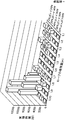
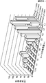
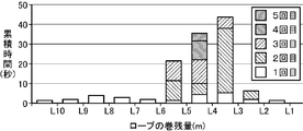
図4及び図5には、吊ロープ統計情報から作成されて蓄積情報閲覧端末14で表示される吊ロープ66についての分布図の一例が示されている。図4は、吊ロープ66の繰出長が比較的小さい状態、すなわち巻上ウインチ61における吊ロープ66の巻残量が比較的大きい状態でクレーン作業を行った場合についての分布図である。図5は、吊ロープ66の繰出長が比較的大きい状態、すなわち巻上ウインチ61における吊ロープ66の巻残量が比較的小さい状態でクレーン作業を行った場合についての分布図である。なお、図4及び図5に記載されたL1~L10は、巻上ウインチ61における吊ロープ66の巻残量を示しており、L1からL10へ向かうにつれて吊ロープ66の巻残量が大きくなる。
吊ロープ66の繰出長が比較的小さい状態でクレーン作業を行った場合には、図4に示されているように、吊ロープ66の巻残量が比較的大きい範囲(L8以上の範囲)での累積時間が大きく、吊ロープ66の繰出長が比較的大きい状態でクレーン作業を行った場合には、図5に示されているように、吊ロープ66の巻残量が比較的小さい範囲(L2~L4の範囲)での累積時間が大きくなっている。すなわち、クレーン作業が、吊ロープ66の繰出長が比較的小さい状態で行われる作業であるか又は吊ロープ66の繰出長が比較的大きい状態で行われる作業であるかによって、吊ロープ66の巻残量に対する累積時間の分布に差異が生じる。
累積時間が吊ロープ66の巻残量の特定の範囲のみに固まっていて他の範囲にほぼ存在しない場合、すなわち吊ロープ66の巻残量における累積時間の偏りが大きい場合には、吊ロープ66の使用部位の偏りが大きいことが示唆される。吊ロープ66の使用部位の偏りが大きい場合には、吊ロープ66の限られた部位に疲労が蓄積されている(吊ロープ66が局所的に痛んでいる)可能性があり、吊ロープ66の交換時期が早くなる可能性がある。一方、分布図において累積時間が分散していてその分布図がなだらかな様相を示している場合には、吊ロープ66の使用部位が分散しており、吊ロープ66の特定の部位に局所的に疲労が蓄積している可能性は低いことが示唆される。
また、負荷率が大きい範囲の累積時間が突出している場合には、吊ロープ66に大きな負荷が長時間かかったことが示唆される。この場合も、吊ロープ66の交換時期が早くなる可能性がある。以上のことから、吊ロープ統計情報から得られる分布図は、吊ロープ66の交換時期の判断の指針となる。
また、起伏ロープ統計情報についても、吊ロープ統計情報から得られる分布図と同様の形態の分布図を得ることができ、その得られた分布図は、起伏ロープ67の交換時期の判断の指針となる。
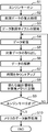
次に、図6のフローチャートを参照して、データロガー28で行われる処理について説明する。
まず、クレーン2のエンジンキーがオンされる(ステップS1)。
このエンジンキーのオンに応じて、データロガー28では、情報処理部32によって前回データの復元処理が行われる(ステップS2)。具体的に、データロガー28の不揮発メモリ34には、クレーン2の前回の稼動の終了時点(前回のエンジンキーのオフ時点)でその前回の稼働中の各種データが不揮発メモリ34に保存されており、情報処理部32は、今回のエンジンキーのオンに応じて、不揮発メモリ34に保存されている前回の最終データを読み出して復元する。より具体的には、情報処理部32は、不揮発メモリ34に保存されている前回の最終データのうちの吊ロープ統計情報及び起伏ロープ統計情報を読み出して復元する。
その後、データロガー28によるデータの取得サイクルが開始される(ステップS3)。
まず、データロガー28がbus30に流れる各種データを受信する(ステップS4)。
そして、情報処理部32は、データロガー28が受信したデータから吊ロープ統計情報及び起伏ロープ統計情報を作成するための対象データを取り出す(ステップS5)。具体的には、情報処理部32は、吊ロープ66,起伏ロープ67についての負荷率のデータ及び吊ロープ66,起伏ロープ67の巻残量のデータを対象データとして取り出す。
次に、情報処理部32は、取得した吊ロープ66,起伏ロープ67についての負荷率のデータ及び吊ロープ66,起伏ロープ67の巻残量のデータの解析を行う(ステップS6)。具体的に、情報処理部32は、上記ステップS2で復元した吊ロープ統計情報の負荷率の複数の区分のうち取得した吊ロープ66についての負荷率が該当する区分を特定するとともに、その吊ロープ統計情報の巻残量の複数の区分のうち取得した吊ロープ66の巻残量が該当する区分を特定する。また、情報処理部32は、上記ステップS2で復元した起伏ロープ統計情報の負荷率の複数の区分のうち取得した起伏ロープ67についての負荷率が該当する区分を特定するとともに、その起伏ロープ統計情報の巻残量の複数の区分のうち取得した起伏ロープ67の巻残量が該当する区分を特定する。
その後、情報処理部32は、吊ロープ統計情報のうち特定した負荷率の区分及び特定した巻残量の区分の両方に対応する時間を情報処理部32によるデータの取得周期(所定周期:1sec)に相当する時間の分だけカウントアップするとともに、起伏ロープ統計情報のうち特定した負荷率の区分及び特定した巻残量の区分の両方に対応する時間を前記データの取得周期に相当する時間の分だけカウントアップする(ステップS7)。
次に、情報処理部32は、時間をカウントアップした後の新たな吊ロープ統計情報及び新たな起伏ロープ統計情報を不揮発メモリ34に記憶させる(ステップS8)。すなわち、情報処理部32は、不揮発メモリ34に記憶されていた吊ロープ統計情報及び起伏ロープ統計情報を、時間をカウントアップした後の新たな吊ロープ統計情報及び新たな起伏ロープ統計情報に更新する。
その後、情報処理部32は、エンジンキーがオフされたか否かの判断を行い(ステップS9)、エンジンキーがまだオフされていないと判断した場合には、上記ステップS4以降のデータ取得サイクルを繰り返し実行する。一方、情報処理部32は、エンジンキーがオフされたと判断した場合には、上記ステップS8で更新された不揮発メモリ34の吊ロープ統計情報及び起伏ロープ統計情報の保存処理を行い(ステップS10)、データロガー28における処理が終了する。
不揮発メモリ34の吊ロープ統計情報及び起伏ロープ統計情報は、エンジンキーのオフ毎に、上記ステップS10で保存処理される吊ロープ統計情報及び起伏ロープ統計情報に更新される。また、情報処理部32は、エンジンキーのオフ毎に、その時点までに不揮発メモリ34に蓄積されたクレーン2の稼働情報の保存処理を行う。
そして、本実施形態では、情報処理部32は、予め設定された所定の期間で不揮発メモリ34に保存されている吊ロープ統計情報及び起伏ロープ統計情報とクレーン2の稼働情報とをまとめた期間データを作成し、その作成した期間データを情報蓄積サーバ10へ携帯電話網6を通じて送信する。
本実施形態では、吊ロープ66についての負荷率及び巻残量と、その負荷率に相当する負荷が吊ロープ66にかかり且つその巻残量に相当する長さの吊ロープ66が巻上ドラム61aに巻かれて残っている状態での累積時間との対応関係を示す吊ロープ統計情報が、提示部9によって提示される。また、起伏ロープ67についての負荷率及び巻残量と、その負荷率に相当する負荷が起伏ロープ67にかかり且つその巻残量に相当する長さの起伏ロープ67が起伏ドラム62aに巻かれて残っている状態での累積時間との対応関係を示す起伏ロープ統計情報が、提示部9によって提示される。
吊ロープ統計情報は、巻上ドラム61aにどの程度の長さの吊ロープ66が巻かれて残っている状態、すなわち巻上ドラム61aからどの程度の長さの吊ロープ66が繰り出された状態でその吊ロープ66にどの程度の負荷がどの程度の累積時間だけかかったかを示すから、この吊ロープ統計情報は、蓄積疲労の観点から吊ロープ66の交換時期を判断するための指針となる。また、起伏ロープ統計情報は、起伏ドラム62aにどの程度の長さの起伏ロープ67が巻かれて残っている状態、すなわち、起伏ドラム62aからどの程度の長さの起伏ロープ67が繰り出された状態でその起伏ロープ67にどの程度の負荷がどの程度の累積時間だけかかったかを示す。よって、この起伏ロープ統計情報は、蓄積疲労の観点から起伏ロープ67の交換時期を判断するための指針となる。従って、本実施形態では、吊ロープ66及び起伏ロープ67の蓄積疲労の観点からそれらの吊ロープ66,起伏ロープ67の交換時期を判断するための指針となる情報を提示できる。
しかも、本実施形態では、吊ロープ統計情報は、吊ロープ66についての負荷率と巻残量の各区分の累積時間の分布を示し、起伏ロープ統計情報は、起伏ロープ67についての負荷率と巻残量の各区分毎の累積時間の分布を示す。すなわち、巻上ドラム61aにどの程度の長さの吊ロープ66が巻かれて残っている状態でその吊ロープ66にどの程度の負荷がかかった状態での累積時間が大きかったかを表す累積時間の分布を吊ロープ統計情報によって提示することができ、起伏ドラム62aにどの程度の長さの起伏ロープ67が巻かれて残っている状態でその起伏ロープ67にどの程度の負荷がかかった状態での累積時間が大きかったかを表す累積時間の分布を起伏ロープ統計情報によって提示することができる。
さらに、本実施形態では、情報蓄積サーバ10が、吊ロープ統計情報及び起伏ロープ統計情報に基づいて、吊ロープ66,起伏ロープ67についての負荷率と巻残量の各区分の累積時間の分布を示す分布図のデータを作成し、蓄積情報閲覧端末14が、情報蓄積サーバ10によって作成された分布図のデータに基づいて、吊ロープ66,起伏ロープ67についての前記分布図を表示する。このため、吊ロープ66,起伏ロープ67にかかった負荷の程度と吊ロープ66,起伏ロープ67の巻残量と累積時間との相関関係を視覚的に一度に把握することができる。
また、本実施形態では、吊ロープ66,起伏ロープ67のうち負荷がかかっている部位を別途新たな測定機器等を用いることなく現実的な実用性で特定できるとともに、クレーン2の姿勢等に左右されない吊ロープ統計情報及び起伏ロープ統計情報を提示できる。
具体的に、吊ロープ66,起伏ロープ67のうち負荷がかかっている部位をクレーン作業中に直接検出することは困難である一方、巻上ウインチ61,起伏ウインチ62の巻上ドラム61a,起伏ドラム62aに巻かれている吊ロープ66,起伏ロープ67の量は各種方法によって一般的に測定されている値であり、また、吊ロープ66,起伏ロープ67の全長は既知の値である。よって、吊ロープ66,起伏ロープ67のうち巻上ドラム61a,起伏ドラム62aから繰り出されている部分の長さは、巻上ドラム61a,起伏ドラム62aにおける吊ロープ66,起伏ロープ67の巻残量から判る値である。このため、巻残量の値に基づいて、吊ロープ66,起伏ロープ67のうち負荷がかかっている極めて局所的な部位そのものは把握できないものの、負荷がかかっているのが吊ロープ66,起伏ロープ67全体におけるどの辺りの部位であるかは把握できる。従って、本実施形態では、巻上ドラム61a,起伏ドラム62aにおける吊ロープ66,起伏ロープ67の巻残量を繰出長指標値として導出することで、別途測定機器等を用いることなく、吊ロープ66,起伏ロープ67のうち負荷のかかっている部位を現実的な実用性で特定できる。また、巻上ドラム61a,起伏ドラム62aにおける吊ロープ66,起伏ロープ67の巻残量はクレーン2の姿勢等に左右されない値であるので、本実施形態では、この巻残量を繰出長指標値として導出することで、クレーン2の姿勢等に左右されない吊ロープ統計情報及び起伏ロープ統計情報を提示できる。
なお、今回開示された実施形態は、すべての点で例示であって制限的なものではないと考えられるべきである。本発明の範囲は、上記した実施形態の説明ではなく特許請求の範囲によって示され、また、特許請求の範囲と均等の意味及び範囲内でのすべての変更を含む。
例えば、吊ロープ統計情報及び起伏ロープ統計情報から吊ロープ66,起伏ロープ67の巻残量のデータを省略してもよい。すなわち、吊ロープ統計情報及び起伏ロープ統計情報は、吊ロープ66,起伏ロープ67についての負荷率と、その負荷率に対応する負荷が吊ロープ66,起伏ロープ67にかかった累積時間との対応関係のみを示すものであってもよい。
また、データロガー28の情報処理部32は、クレーン2の稼働停止時、すなわち、エンジン停止時における作業装置50の状態の情報及びクレーン2の作業姿勢の情報を取得して不揮発メモリ34に保存するとともに、その保存した情報を提示部9へ送信してもよい。この場合、提示部9は、受信したクレーン2の稼働停止時の作業装置50の状態及びクレーン2の作業姿勢の情報を提示する。
クレーン2が稼働を停止している状態では、吊ロープ66,起伏ロープ67は移動せずに一定の位置で保持されているが、対応する巻上ドラム61a,起伏ドラム62aから繰り出された吊ロープ66,起伏ロープ67のうち所定の部位には負担がかかっている。例えば、吊ロープ66のうち巻上ドラム61aの巻き取り口にあたる部位や、トップシーブ51aに沿って曲がった部位、フックシーブに沿って曲がった部位などには、吊ロープ66が一定の位置で保持されている状態であっても負担がかかっている。また、起伏ロープ67のうち起伏ドラム62aの巻き取り口にあたる部位や、ガントリ側スプレッダ56のシーブに沿って曲がった部位、マスト側スプレッダ55のシーブに沿って曲がった部位などには、起伏ロープ67が一定の位置で保持されている状態であっても負担がかかっている。
クレーン2の稼働停止中に負担がかかる吊ロープ66,起伏ロープ67の各部位は、クレーン2の稼働停止中の作業装置50の状態及びクレーン2の作業姿勢に応じて異なるが、その作業装置50の状態及びクレーン2の作業姿勢が判明することによって、その負担がかかる各部位を概ね特定できる。そのため、上記のように提示部9が提示するクレーン2の稼働停止時の作業装置50の状態及びクレーン2の作業姿勢の情報は、クレーン2の稼働停止中に吊ロープ66及び起伏ロープ67に負担がかかった部位を示唆する情報となる。
また、上記実施形態では、データロガー28の情報処理部32が吊ロープ統計情報及び起伏ロープ統計情報を作成し、その情報処理部32によって作成された統計情報に基づいて情報蓄積サーバ10が吊ロープ66についての累積時間の分布図のデータ及び起伏ロープ67についての累積時間の分布図のデータを作成したが、本発明による情報処理の構成は必ずしもこのような構成に限定されない。
例えば、情報処理部32が、吊ロープ66,起伏ロープ67についての負荷率及び巻残量のデータの取得、吊ロープ統計情報及び起伏ロープ統計情報の作成、及び、吊ロープ66,起伏ロープ67についての累積時間の分布図のデータの作成を全て行ってもよい。この場合、情報処理部32は、作成した吊ロープ66,起伏ロープ67についての累積時間の分布図のデータを提示部9の情報蓄積サーバ10へ送信する。そして、情報蓄積サーバ10は、受信した分布図のデータを蓄積して保存し、その保存された分布図のデータを蓄積情報閲覧端末14で閲覧できるようにすればよい。
また、この場合、情報処理部32は、作成した吊ロープ66,起伏ロープ67についての累積時間の分布図のデータに基づいて、そのデータに対応する分布図をクレーン2に設けられた操作パネルに表示させてもよい。
また、図7に示すように、クレーン情報閲覧端末36をUSB(Universal Serial Bus)等の通信ライン37経由でデータロガー28の不揮発メモリ34に接続し、その不揮発メモリ34に保存された吊ロープ統計情報及び起伏ロープ統計情報をクレーン情報閲覧端末36へコピーしてもよい。クレーン情報閲覧端末36としては、例えばパーソナルコンピュータが用いられる。そして、コピーした統計情報をクレーン情報閲覧端末36においてアプリケーションソフトウェアで解析して吊ロープ66,起伏ロープ67についての累積時間の分布図のデータを作成してもよい。クレーン情報閲覧端末36で作成された分布図は、クレーン情報閲覧端末36で閲覧できる。クレーン情報閲覧端末36は、本発明による提示部の概念に含まれる。
また、この場合には、情報蓄積サーバ10へ吊ロープ統計情報及び起伏ロープ統計情報の期間データが送信されるのを待つことなく、現時点で不揮発メモリ34に記憶されている吊ロープ統計情報及び起伏ロープ統計情報から作成した吊ロープ66,起伏ロープ67についての分布図(例えば図8参照)をクレーン情報閲覧端末36で閲覧することが可能である。
なお、不揮発メモリ34からクレーン情報閲覧端末36に吊ロープ統計情報及び起伏ロープ統計情報をコピーする手段として、USBメモリ等の記憶媒体を用いてもよい。
また、データロガー28の情報処理部32は、取得した吊ロープ66,起伏ロープ67についての負荷率及び巻残量のデータを解析することなく提示部9の情報蓄積サーバ10へ送信してもよい。この場合、情報蓄積サーバ10が、受信した吊ロープ66,起伏ロープ67についての負荷率及び巻残量のデータに基づいて吊ロープ統計情報及び起伏ロープ統計情報を作成し、その作成した統計情報から吊ロープ66,起伏ロープ67についての累積時間の分布図のデータを作成するようにしてもよい。この場合、情報蓄積サーバ10は、本発明における情報処理装置の概念に含まれる。
また、この構成において、情報蓄積サーバ10が分布図のデータを作成する替わりに、蓄積情報閲覧端末14が分布図のデータを作成してもよい。すなわち、情報蓄積サーバ10から蓄積情報閲覧端末14へ吊ロープ統計情報及び起伏ロープ統計情報をダウンロードし、そのダウンロードした統計情報を蓄積情報閲覧端末14にてアプリケーションソフトウェアで解析して吊ロープ66,起伏ロープ67についての累積時間の分布図のデータを作成してもよい。
また、データロガー28(情報処理部32)から情報蓄積サーバ10へデータを送信するために用いる通信網は、必ずしも携帯電話網6に限定されない。例えば、LAN(Local Area Network)やその他の通信網を用いてもよい。
また、情報処理部32は、大負荷状態が発生した累積時間を吊ロープ66,起伏ロープ67の繰出長の区分毎に示す負荷情報を作成して不揮発メモリ34に保存し、吊ロープ統計情報及び起伏ロープ統計情報に加えてこの負荷情報も情報蓄積サーバ10へ送信してもよい。そして、情報蓄積サーバ10は、受信した負荷情報から図9に示すような負荷分布図のデータを作成し、その作成された負荷分布図を蓄積情報閲覧端末14で閲覧できるようにしてもよい。
具体的に、前記大負荷状態は、負荷率が80%以上で且つ100%以下になった状態であり、情報処理部32は、吊ロープ統計情報及び起伏ロープ統計情報のうちの80%以上100%以下の負荷率の区分の累積時間と吊ロープ66,起伏ロープ67の巻残量との対応関係のデータを抜き出して負荷情報を作成する。また、情報処理部32は、大負荷状態の発生回数、すなわち取得した負荷率が80%以上で且つ100%以下になった回数をカウントするとともに、各回の大負荷状態の継続時間をカウントし、それによって得た大負荷状態の発生回数及び各回の大負荷状態の継続時間のデータを負荷情報に加える。情報処理部32により取得された負荷情報は、データロガー28の不揮発メモリ34に保存され、情報蓄積サーバ10へ送信される。情報蓄積サーバ10は、受信した負荷情報に基づいて負荷分布図(図9参照)のデータを作成する。
負荷分布図は、吊ロープ66,起伏ロープ67の巻残量の各区分に大負荷状態が発生した累積時間がバーで示されたグラフであり、巻残量の各区分の累積時間のバーに大負荷状態の発生回数を表す識別表示(色分け等)が付されるとともに、その識別表示された各発生回の縦軸(累積時間軸)方向の長さがその発生回の大負荷状態の継続時間を表すようになっている。
負荷分布図を蓄積情報閲覧端末14で閲覧できることにより、閲覧者は、吊ロープ66,起伏ロープ67に大きな負荷がどれだけの時間かかったかを把握することができるとともに、その大きな負荷がかかった回数及びその各回の負荷がかかった継続時間を把握することができる。
なお、情報蓄積サーバ10の替わりに、データロガー28の情報処理部32もしくは蓄積情報閲覧端末14が負荷分布図のデータを作成してもよい。
また、クレーン2は、吊ロープ統計情報及び起伏ロープ統計情報に基づいて吊ロープ66,起伏ロープ67の点検を促すための報知を行う報知部を備えていてもよい。
例えば、クレーン2は、報知部として、オペレータに吊ロープ66,起伏ロープ67の点検を促すメッセージを表示する表示モニタ等を備えていてもよい。この場合、例えば、データロガー28の情報処理部32が、クレーン2の吊能力が異なる作業姿勢毎に吊ロープ統計情報の累積時間を集計して吊ロープ66の使用時間を算出するとともに、その算出した使用時間が規定の時間を超えた時点で表示モニタに吊ロープ66の点検を促すメッセージを表示させればよい。また、情報処理部32は、起伏ロープ67の使用時間についても同様に起伏ロープ統計情報から算出して、その算出した使用時間が規定の時間を超えた時点で表示モニタに起伏ロープ67の点検を促すメッセージを表示させればよい。
また、報知部として、表示モニタの替わりに、オペレータに吊ロープ66,起伏ロープ67の点検を促す音を発するブザーや、点灯することによって吊ロープ66,起伏ロープ67の点検を促すランプ等を用いてもよい。
また、クレーン2は、吊ロープ66,起伏ロープ67の直径を測定する測定装置を備え、データロガー28の情報処理部32は、測定装置によって測定された吊ロープ66,起伏ロープ67の直径のデータを取得して不揮発メモリ34に蓄積してもよい。そして、情報処理部32は不揮発メモリ34に蓄積した吊ロープ66,起伏ロープ67の直径のデータを提示部9へ送信し、提示部9は受信した吊ロープ66,起伏ロープ67の直径のデータを吊ロープ統計情報及び起伏ロープ統計情報とともに提示してもよい。
この構成によれば、吊ロープ66,起伏ロープ67にかかった負荷の大きさ及び吊ロープ66,起伏ロープ67の巻残量についての情報に加えて、吊ロープ66,起伏ロープ67の直径の経時変化の情報を提示できる。ワイヤロープは、それにかかる負荷が大きくなるにつれて伸び、その直径が小さくなる。また、ワイヤロープに疲労が蓄積されて素線切れが生じた場合には、ワイヤロープの直径が減少する。従って、吊ロープ66,起伏ロープ67の直径の経時変化の情報は、吊ロープ66,起伏ロープ67の交換時期の指針となり、この情報が吊ロープ統計情報及び起伏ロープ統計情報に加えて提示されることによって、吊ロープ66,起伏ロープ67の交換時期をより精度良く判断するための指針となる情報を提示することができる。
また、本発明による負荷指標値として、負荷率の代わりに、吊ロープ66,起伏ロープ67にかかる実荷重を用いてもよい。
また、吊ロープ統計情報及び起伏ロープ統計情報の統計表において累積時間の各セル毎に吊ロープ66,起伏ロープ67の疲労についての重み付けを設定してもよい。すなわち、吊ロープ66,起伏ロープ67の過去のメンテナンス情報から吊ロープ66,起伏ロープ67が痛みやすい巻残量の条件を導出し、その導出した条件に基づいて痛みやすい巻残量の区分に属するセルは重み付けを大きくし、比較的痛みにくい巻残量の区分に属するセルは重み付けを小さくすればよい。また、負荷率が大きい区分になるほど、その区分のセルの重み付けを大きくすればよい。
また、吊ロープ66,起伏ロープ67についての分布図において、累積時間の分布の重心を導出するとともに負荷率の軸方向における分散及び巻残量の軸方向における分散などを算出することによって、クレーン作業時の吊ロープ66,起伏ロープ67の使われ方についての特徴量を導出してもよい。例えば、あるワイヤロープを吊ロープ66として使用してクレーン作業を行っている期間に前記特徴量を導出する。その後、ワイヤロープを交換して別のワイヤロープを吊ロープ66として使用してクレーン作業を行うときに同様に前記特徴量を導出し、この導出した特徴量が交換前のワイヤロープについて導出した特徴量と等しい場合には、交換後の吊ロープ66の使われ方が交換前のワイヤロープの使われ方と同じであることが示唆される。また、起伏ロープ67についても同様である。
また、巻上ウインチ61における吊ロープ66の巻残量に基づいて巻上ウインチ61からの吊ロープ66の繰出長を導出し、その導出した繰出長を本発明による繰出長指標値としてもよい。また、起伏ウインチ62における起伏ロープ67の巻残量に基づいて起伏ウインチ62からの起伏ロープ67の繰出長を導出し、その導出した繰出長を本発明による繰出長指標値としてもよい。
この場合、例えば、データロガー28に繰出長演算部を設けて、その繰出長演算部が予め登録された吊ロープ66の全長から第1メインコントローラ21によって算出された吊ロープ66の巻残量を減算することにより吊ロープ66の繰出長を算出してもよい。また、繰出長演算部が予め登録された起伏ロープ67の全長から第2メインコントローラ22によって算出された起伏ロープ67の巻残量を減算することによって起伏ロープ67の繰出長を算出してもよい。また、データロガー28に繰出長演算部を設けず、第1メインコントローラ21が吊ロープ66の繰出長を算出し、第2メインコントローラ22が起伏ロープ67の繰出長を算出してもよい。そして、算出された吊ロープ66,起伏ロープ67の繰出長を吊ロープ66,起伏ロープ67の巻残量の替わりに用いて、上記した各統計情報や累積時間の分布データ、分布図等を作成して提示してもよい。
本実施の形態は以下のように纏められる。
本実施の形態は以下のように纏められる。
本実施の形態によるクレーンの情報提示システムは、ワイヤロープの繰り出し及び巻き取りを行って対象物を上下に動作させるウインチを備えたクレーンの前記ワイヤロープについての情報を提示するシステムであって、
前記ワイヤロープにかかる負荷の指標値である負荷指標値を所定周期で導出する負荷指標導出部と、
前記負荷指標値を前記所定周期で取得することで、前記負荷指標値に対応する負荷が前記ワイヤロープにかかった状態の累積時間と、前記負荷指標値との対応関係を示す統計情報を作成する情報処理装置と、
前記情報処理装置により作成された前記統計情報を提示する提示部と、を備える。
前記ワイヤロープにかかる負荷の指標値である負荷指標値を所定周期で導出する負荷指標導出部と、
前記負荷指標値を前記所定周期で取得することで、前記負荷指標値に対応する負荷が前記ワイヤロープにかかった状態の累積時間と、前記負荷指標値との対応関係を示す統計情報を作成する情報処理装置と、
前記情報処理装置により作成された前記統計情報を提示する提示部と、を備える。
このクレーンの情報提示システムでは、ワイヤロープにかかる負荷の指標値である負荷指標値とその負荷指標値に対応する負荷がワイヤロープにかかった状態での累積時間との対応関係を示す統計情報が提示部によって提示される。そのため、その提示された統計情報に基づいて、ワイヤロープにどの程度の負荷がどの程度の累積時間だけかかったかを把握することができる。従って、この情報提示システムによれば、クレーンのウインチで用いられるワイヤロープの蓄積疲労の観点からそのワイヤロープの交換時期を判断するための指針となる情報を提示できる。
前記クレーンの情報提示システムにおいて、
前記ウインチから繰り出された前記ワイヤロープの長さの指標値である繰出長指標値を前記所定周期で導出する繰出長指標導出部をさらに備え、
前記情報処理装置は、前記負荷指標値及び前記繰出長指標値を前記所定周期で取得することで、前記繰出長指標値に対応する長さで繰り出されている前記ワイヤーロープに対し、前記負荷指標値に対応する負荷がかかった状態の累積時間と、前記負荷指標値と、前記繰出長指標値との対応関係を示す負荷繰出長統計情報を前記統計情報として作成し、
前記提示部は、前記情報処理装置により作成された前記負荷繰出長統計情報を提示することが好ましい。
前記ウインチから繰り出された前記ワイヤロープの長さの指標値である繰出長指標値を前記所定周期で導出する繰出長指標導出部をさらに備え、
前記情報処理装置は、前記負荷指標値及び前記繰出長指標値を前記所定周期で取得することで、前記繰出長指標値に対応する長さで繰り出されている前記ワイヤーロープに対し、前記負荷指標値に対応する負荷がかかった状態の累積時間と、前記負荷指標値と、前記繰出長指標値との対応関係を示す負荷繰出長統計情報を前記統計情報として作成し、
前記提示部は、前記情報処理装置により作成された前記負荷繰出長統計情報を提示することが好ましい。
この構成によれば、負荷指標値と繰出長指標値と累積時間との対応関係を示す負荷繰出長統計情報が提示部によって提示される。すなわち、この提示部によって提示される負荷繰出長統計情報により、ウインチからどの程度の長さのワイヤロープが繰り出された状態でそのワイヤロープにどの程度の負荷がどの程度の累積時間だけかかったかを示すことができる。
この場合において、前記情報処理装置は、前記負荷指標値と前記繰出長指標値とをそれぞれ複数の区分に分類し、各区分に対応する前記累積時間を算出し、各区分の前記累積時間の分布を示す累積時間分布データを前記負荷繰出長統計情報として作成することが好ましい。
この構成によれば、負荷指標値と繰出長指標値との各区分の累積時間の分布を示す累積時間分布データが得られ、その累積時間分布データを提示部によって提示することができる。すなわち、ウインチからどの程度の長さのワイヤロープが繰り出された状態でそのワイヤロープにどの程度の負荷がかかった状態での累積時間が大きかったかを表す累積時間分布データを提示することができる。
さらにこの場合において、前記提示部は、前記情報処置装置によって作成された前記累積時間分布データが示す各区分の前記累積時間の分布を表示する表示部を有することが好ましい。
この構成によれば、負荷指標値と繰出長指標値との各区分の累積時間の分布が表示部によって表示されるため、ワイヤロープにかかった負荷の程度とワイヤロープの繰出長と累積時間との相関関係を視覚的に一度に把握することができる。
前記繰出長指標導出部は、前記ウインチに残った前記ワイヤロープの長さである巻残量を前記繰出長指標値として導出することが好ましい。
この構成によれば、ワイヤロープのうち負荷がかかっている部位を別途新たな測定機器等を用いることなく現実的な実用性で特定できるとともに、クレーンの姿勢等に左右されない負荷繰出長統計情報を提示できる。具体的に、ワイヤロープのうち負荷がかかっている部位をクレーン作業中に直接検出することは困難である一方、ウインチに巻かれているワイヤロープの量は各種方法によって一般的に測定されている値であり、また、ワイヤロープの全長は既知の値である。よって、ワイヤロープのうちウインチから繰り出されている部分の長さは、ウインチにおけるワイヤロープの巻残量から判る値である。このため、巻残量の値に基づいて、ワイヤロープのうち負荷がかかっている極めて局所的な部位そのものは把握できないものの、負荷がかかっているのがワイヤロープ全体におけるどの辺りの部位であるかは把握できる。従って、本構成によれば、ウインチにおけるワイヤロープの巻残量を繰出長指標値として導出することで、別途新たな測定機器等を用いることなく、ワイヤロープのうち負荷のかかっている部位を現実的な実用性で特定できる。また、ウインチにおけるワイヤロープの巻残量はクレーンの姿勢等に左右されない値であるので、本構成では、この巻残量を繰出長指標値として導出することで、クレーンの姿勢等に左右されない負荷繰出長統計情報を提示できる。
Claims (7)
- ワイヤロープの繰り出し及び巻き取りを行って対象物を上下に動作させるウインチを備えたクレーンの前記ワイヤロープについての情報を提示するシステムであって、
前記ワイヤロープにかかる負荷の指標値である負荷指標値を所定周期で導出する負荷指標導出部と、
前記負荷指標値を前記所定周期で取得することで、前記負荷指標値に対応する負荷が前記ワイヤロープにかかった状態の累積時間と、前記負荷指標値との対応関係を示す統計情報を作成する情報処理装置と、
前記情報処理装置により作成された前記統計情報を提示する提示部と、を備える、
クレーンの情報提示システム。 - 前記ウインチから繰り出された前記ワイヤロープの長さの指標値である繰出長指標値を前記所定周期で導出する繰出長指標導出部をさらに備え、
前記情報処理装置は、前記負荷指標値及び前記繰出長指標値を前記所定周期で取得することで、前記繰出長指標値に対応する長さで繰り出されている前記ワイヤーロープに対し、前記負荷指標値に対応する負荷がかかった状態の累積時間と、前記負荷指標値と、前記繰出長指標値との対応関係を示す負荷繰出長統計情報を前記統計情報として作成し、
前記提示部は、前記情報処理装置により作成された前記負荷繰出長統計情報を提示する、
請求項1に記載のクレーンの情報提示システム。 - 前記情報処理装置は、前記負荷指標値と前記繰出長指標値とをそれぞれ複数の区分に分類し、各区分に対応する前記累積時間を算出し、各区分の前記累積時間の分布を示す累積時間分布データを前記負荷繰出長統計情報として作成する、
請求項2に記載のクレーンの情報提示システム。 - 前記提示部は、前記情報処置装置によって作成された前記累積時間分布データが示す各区分の前記累積時間の分布を表示する表示部を有する、
請求項3に記載のクレーンの情報提示システム。 - 前記繰出長指標導出部は、前記ウインチに残った前記ワイヤロープの長さである巻残量を前記繰出長指標値として導出する、
請求項2~4のいずれか1項に記載のクレーンの情報提示システム。 - 前記ワイヤロープにかかる負荷を検出する負荷センサをさらに備え、
前記情報処理装置は、前記負荷センサが検出した負荷に基づいて、前記負荷指標値を所定周期で導出する
請求項1記載のクレーンの情報提示システム。 - 前記ワイヤロープが巻かれたドラムの回転量を検出する回転量センサをさらに備え、
前記繰出長指標導出部は、前記回転量センサが検出した回転量に基づいて、前記繰出長指標値を前記所定周期で導出する
請求項2記載のクレーンの情報提示システム。
Priority Applications (1)
| Application Number | Priority Date | Filing Date | Title |
|---|---|---|---|
| US15/562,188 US10633225B2 (en) | 2015-04-01 | 2016-03-30 | Crane information presentation system |
Applications Claiming Priority (2)
| Application Number | Priority Date | Filing Date | Title |
|---|---|---|---|
| JP2015075029A JP6123835B2 (ja) | 2015-04-01 | 2015-04-01 | クレーンの情報提示システム |
| JP2015-075029 | 2015-04-01 |
Publications (1)
| Publication Number | Publication Date |
|---|---|
| WO2016159128A1 true WO2016159128A1 (ja) | 2016-10-06 |
Family
ID=57005767
Family Applications (1)
| Application Number | Title | Priority Date | Filing Date |
|---|---|---|---|
| PCT/JP2016/060475 Ceased WO2016159128A1 (ja) | 2015-04-01 | 2016-03-30 | クレーンの情報提示システム |
Country Status (3)
| Country | Link |
|---|---|
| US (1) | US10633225B2 (ja) |
| JP (1) | JP6123835B2 (ja) |
| WO (1) | WO2016159128A1 (ja) |
Cited By (2)
| Publication number | Priority date | Publication date | Assignee | Title |
|---|---|---|---|---|
| WO2020016625A1 (en) | 2018-07-16 | 2020-01-23 | Tractel Inc. | Hoist apparatus comprising a monitoring device and management system using the hoist apparatus |
| EP4328173A4 (en) * | 2021-04-20 | 2025-04-23 | Tadano Ltd. | Device for estimating number of wound layers, and crane |
Families Citing this family (10)
| Publication number | Priority date | Publication date | Assignee | Title |
|---|---|---|---|---|
| DE102016008819A1 (de) * | 2016-07-19 | 2018-01-25 | Liebherr-Werk Nenzing Gmbh | Schlagzahloptimierung |
| JP6753337B2 (ja) * | 2017-03-03 | 2020-09-09 | コベルコ建機株式会社 | クレーンの情報提示システム及びクレーン |
| EP3831764A4 (en) * | 2018-07-27 | 2022-02-23 | Sumitomo (S.H.I.) Construction Machinery Co., Ltd. | WORK MACHINE |
| CN108815831A (zh) * | 2018-09-23 | 2018-11-16 | 姚前 | 一种习练装置及其使用、控制方法 |
| JP7370142B2 (ja) * | 2019-02-06 | 2023-10-27 | 住友重機械搬送システム株式会社 | クレーンシステム、及びクレーンシステムの監視方法 |
| US10994970B2 (en) | 2019-07-29 | 2021-05-04 | Jim D. Wiethorn | Crane risk logic apparatus and system and method for use of same |
| JP7467471B2 (ja) * | 2019-07-29 | 2024-04-15 | 住友建機株式会社 | ショベル |
| US20210122616A1 (en) * | 2019-10-29 | 2021-04-29 | KTM Solutions, Inc. | Smart Lift Device |
| US11288897B2 (en) | 2020-08-20 | 2022-03-29 | Jim D. Wiethorn | Crane risk logic apparatus and system and method for use of same |
| EP4174014A1 (en) * | 2021-11-02 | 2023-05-03 | Hiab AB | A loader crane system |
Citations (3)
| Publication number | Priority date | Publication date | Assignee | Title |
|---|---|---|---|---|
| JP2004067379A (ja) * | 2002-08-09 | 2004-03-04 | Ishikawajima Transport Machinery Co Ltd | 作業状態検出装置 |
| JP2008127129A (ja) * | 2006-11-17 | 2008-06-05 | Kobelco Cranes Co Ltd | 建設機械用メンテナンス情報管理装置及び建設機械用メンテナンス情報管理方法 |
| JP2010159108A (ja) * | 2009-01-07 | 2010-07-22 | Kobelco Cranes Co Ltd | クレーンの運転評価装置 |
Family Cites Families (8)
| Publication number | Priority date | Publication date | Assignee | Title |
|---|---|---|---|---|
| US6758356B1 (en) * | 1989-10-10 | 2004-07-06 | Manitowoc Crane Companies, Inc. | Liftcrane with synchronous rope operation |
| US5645181A (en) * | 1992-02-12 | 1997-07-08 | Kato Works Co., Ltd. | Method for detecting a crane hook lifting distance |
| JPH11240689A (ja) | 1998-02-25 | 1999-09-07 | Hitachi Constr Mach Co Ltd | ロープ残巻検出装置および巻上装置 |
| DE10233875B4 (de) * | 2002-07-25 | 2008-08-14 | Siemens Ag | Krananlage, insbesondere Containerkran |
| GB0819400D0 (en) * | 2008-10-22 | 2008-11-26 | Subsea 7 | Offshore lifting operations |
| US8640895B2 (en) * | 2009-07-28 | 2014-02-04 | Manitowoc Crane Companies, Llc | Drum tensioning method and apparatus for load hoist wire rope |
| DE202011001846U1 (de) * | 2011-01-24 | 2012-04-30 | Liebherr-Components Biberach Gmbh | Vorrichtung zur Erkennung der Ablegereife eines hochfesten Faserseils beim Einsatz an Hebezeugen |
| JP6121663B2 (ja) * | 2012-07-10 | 2017-04-26 | 株式会社タダノ | 作業車両 |
-
2015
- 2015-04-01 JP JP2015075029A patent/JP6123835B2/ja active Active
-
2016
- 2016-03-30 US US15/562,188 patent/US10633225B2/en active Active
- 2016-03-30 WO PCT/JP2016/060475 patent/WO2016159128A1/ja not_active Ceased
Patent Citations (3)
| Publication number | Priority date | Publication date | Assignee | Title |
|---|---|---|---|---|
| JP2004067379A (ja) * | 2002-08-09 | 2004-03-04 | Ishikawajima Transport Machinery Co Ltd | 作業状態検出装置 |
| JP2008127129A (ja) * | 2006-11-17 | 2008-06-05 | Kobelco Cranes Co Ltd | 建設機械用メンテナンス情報管理装置及び建設機械用メンテナンス情報管理方法 |
| JP2010159108A (ja) * | 2009-01-07 | 2010-07-22 | Kobelco Cranes Co Ltd | クレーンの運転評価装置 |
Cited By (3)
| Publication number | Priority date | Publication date | Assignee | Title |
|---|---|---|---|---|
| WO2020016625A1 (en) | 2018-07-16 | 2020-01-23 | Tractel Inc. | Hoist apparatus comprising a monitoring device and management system using the hoist apparatus |
| US12552647B2 (en) | 2018-07-16 | 2026-02-17 | Tractel Inc. | Hoist apparatus comprising a monitoring device and management system using the hoist apparatus |
| EP4328173A4 (en) * | 2021-04-20 | 2025-04-23 | Tadano Ltd. | Device for estimating number of wound layers, and crane |
Also Published As
| Publication number | Publication date |
|---|---|
| US20180057319A1 (en) | 2018-03-01 |
| US10633225B2 (en) | 2020-04-28 |
| JP6123835B2 (ja) | 2017-05-10 |
| JP2016193789A (ja) | 2016-11-17 |
Similar Documents
| Publication | Publication Date | Title |
|---|---|---|
| JP6123835B2 (ja) | クレーンの情報提示システム | |
| CN102272035B (zh) | 起重机操纵评估装置 | |
| JP7152145B2 (ja) | クレーンのホイスト及びロープの光学的な検出及び分析 | |
| CN105438983B (zh) | 一种工程机械及其卷扬乱绳监测装置和方法 | |
| EP3307667B1 (en) | System and method for the calculation of capacity charts at intermediate counterweight positions | |
| CN115140654B (zh) | 绞车卷筒的监视装置 | |
| CN112839896B (zh) | 起重机装置、股数判定方法以及记录介质 | |
| US10703612B2 (en) | System and method for calculation of capacity charts at a locked counterweight position | |
| CN114014188B (zh) | 起重机风险预防方法及装置 | |
| JP2022138304A (ja) | ウインチ監視方法、ウインチ監視装置、クレーン | |
| CN108883919A (zh) | 起重机 | |
| JP4735518B2 (ja) | 建設機械用メンテナンス情報管理装置及び建設機械用メンテナンス情報管理方法 | |
| JP6729211B2 (ja) | クレーンの情報提示システム | |
| JP7283263B2 (ja) | クレーン、クレーンにおけるウエイト状態判定方法 | |
| JP6956645B2 (ja) | 吊荷重演算装置 | |
| CN203602279U (zh) | 一种吊钩垂下高度的检测系统及起重机 | |
| JP2010247996A (ja) | 建設機械用メンテナンス情報管理装置及び建設機械用メンテナンス情報管理方法 | |
| JP2682951B2 (ja) | ジブ起伏ロープの寿命判定装置 | |
| JP7067377B2 (ja) | 作業機械の荷重表示装置 | |
| WO2023071207A1 (zh) | 双卷扬乱绳识别方法、装置、吊装机械、电子设备、计算机可读存储介质以及计算机产品 | |
| CN216971789U (zh) | 一种折臂吊智能计重系统 | |
| JP2769084B2 (ja) | ジブ俯仰ロープの寿命判定装置 | |
| JP2769085B2 (ja) | ジブ俯仰ロープの寿命判定装置 | |
| JPH06263384A (ja) | 移動式クレーンの最大フック降下位置算出装置 |
Legal Events
| Date | Code | Title | Description |
|---|---|---|---|
| 121 | Ep: the epo has been informed by wipo that ep was designated in this application |
Ref document number: 16773009 Country of ref document: EP Kind code of ref document: A1 |
|
| WWE | Wipo information: entry into national phase |
Ref document number: 15562188 Country of ref document: US |
|
| NENP | Non-entry into the national phase |
Ref country code: DE |
|
| 122 | Ep: pct application non-entry in european phase |
Ref document number: 16773009 Country of ref document: EP Kind code of ref document: A1 |