WO2016158713A1 - 画像読取装置、画像処理装置、画像読取方法 - Google Patents
画像読取装置、画像処理装置、画像読取方法 Download PDFInfo
- Publication number
- WO2016158713A1 WO2016158713A1 PCT/JP2016/059538 JP2016059538W WO2016158713A1 WO 2016158713 A1 WO2016158713 A1 WO 2016158713A1 JP 2016059538 W JP2016059538 W JP 2016059538W WO 2016158713 A1 WO2016158713 A1 WO 2016158713A1
- Authority
- WO
- WIPO (PCT)
- Prior art keywords
- image
- unit
- light emitting
- image data
- data sequence
- Prior art date
- Legal status (The legal status is an assumption and is not a legal conclusion. Google has not performed a legal analysis and makes no representation as to the accuracy of the status listed.)
- Ceased
Links
Images






Classifications
-
- H—ELECTRICITY
- H04—ELECTRIC COMMUNICATION TECHNIQUE
- H04N—PICTORIAL COMMUNICATION, e.g. TELEVISION
- H04N1/00—Scanning, transmission or reproduction of documents or the like, e.g. facsimile transmission; Details thereof
- H04N1/40—Picture signal circuits
- H04N1/409—Edge or detail enhancement; Noise or error suppression
- H04N1/4097—Removing errors due external factors, e.g. dust, scratches
-
- H—ELECTRICITY
- H04—ELECTRIC COMMUNICATION TECHNIQUE
- H04N—PICTORIAL COMMUNICATION, e.g. TELEVISION
- H04N1/00—Scanning, transmission or reproduction of documents or the like, e.g. facsimile transmission; Details thereof
- H04N1/00835—Detecting external or ambient light
-
- H—ELECTRICITY
- H04—ELECTRIC COMMUNICATION TECHNIQUE
- H04N—PICTORIAL COMMUNICATION, e.g. TELEVISION
- H04N1/00—Scanning, transmission or reproduction of documents or the like, e.g. facsimile transmission; Details thereof
- H04N1/024—Details of scanning heads ; Means for illuminating the original
- H04N1/028—Details of scanning heads ; Means for illuminating the original for picture information pick-up
- H04N1/02815—Means for illuminating the original, not specific to a particular type of pick-up head
-
- H—ELECTRICITY
- H04—ELECTRIC COMMUNICATION TECHNIQUE
- H04N—PICTORIAL COMMUNICATION, e.g. TELEVISION
- H04N1/00—Scanning, transmission or reproduction of documents or the like, e.g. facsimile transmission; Details thereof
- H04N1/04—Scanning arrangements, i.e. arrangements for the displacement of active reading or reproducing elements relative to the original or reproducing medium, or vice versa
-
- H—ELECTRICITY
- H04—ELECTRIC COMMUNICATION TECHNIQUE
- H04N—PICTORIAL COMMUNICATION, e.g. TELEVISION
- H04N1/00—Scanning, transmission or reproduction of documents or the like, e.g. facsimile transmission; Details thereof
- H04N1/04—Scanning arrangements, i.e. arrangements for the displacement of active reading or reproducing elements relative to the original or reproducing medium, or vice versa
- H04N1/10—Scanning arrangements, i.e. arrangements for the displacement of active reading or reproducing elements relative to the original or reproducing medium, or vice versa using flat picture-bearing surfaces
-
- H—ELECTRICITY
- H04—ELECTRIC COMMUNICATION TECHNIQUE
- H04N—PICTORIAL COMMUNICATION, e.g. TELEVISION
- H04N1/00—Scanning, transmission or reproduction of documents or the like, e.g. facsimile transmission; Details thereof
- H04N1/04—Scanning arrangements, i.e. arrangements for the displacement of active reading or reproducing elements relative to the original or reproducing medium, or vice versa
- H04N1/10—Scanning arrangements, i.e. arrangements for the displacement of active reading or reproducing elements relative to the original or reproducing medium, or vice versa using flat picture-bearing surfaces
- H04N1/107—Scanning arrangements, i.e. arrangements for the displacement of active reading or reproducing elements relative to the original or reproducing medium, or vice versa using flat picture-bearing surfaces with manual scanning
-
- H—ELECTRICITY
- H04—ELECTRIC COMMUNICATION TECHNIQUE
- H04N—PICTORIAL COMMUNICATION, e.g. TELEVISION
- H04N1/00—Scanning, transmission or reproduction of documents or the like, e.g. facsimile transmission; Details thereof
- H04N1/387—Composing, repositioning or otherwise geometrically modifying originals
- H04N1/3872—Repositioning or masking
- H04N1/3873—Repositioning or masking defined only by a limited number of coordinate points or parameters, e.g. corners, centre; for trimming
-
- H—ELECTRICITY
- H04—ELECTRIC COMMUNICATION TECHNIQUE
- H04N—PICTORIAL COMMUNICATION, e.g. TELEVISION
- H04N1/00—Scanning, transmission or reproduction of documents or the like, e.g. facsimile transmission; Details thereof
- H04N1/40—Picture signal circuits
- H04N1/407—Control or modification of tonal gradation or of extreme levels, e.g. background level
- H04N1/4072—Control or modification of tonal gradation or of extreme levels, e.g. background level dependent on the contents of the original
-
- H—ELECTRICITY
- H04—ELECTRIC COMMUNICATION TECHNIQUE
- H04N—PICTORIAL COMMUNICATION, e.g. TELEVISION
- H04N2201/00—Indexing scheme relating to scanning, transmission or reproduction of documents or the like, and to details thereof
- H04N2201/0077—Types of the still picture apparatus
- H04N2201/0094—Multifunctional device, i.e. a device capable of all of reading, reproducing, copying, facsimile transception, file transception
Definitions
- the present invention relates to an image reading apparatus, an image processing apparatus including the same, and an image reading method.
- an image reading apparatus includes an image scanning unit that scans a document while detecting the amount of light emitted from the document placed on a transparent document table.
- the image scanning unit includes a light emitting unit that irradiates light on a document and an image sensor that receives reflected light from a linear region along the main scanning direction of the document, and scans the document along the sub-scanning direction.
- the image sensor outputs a data string corresponding to the detected light amount for each pixel of the linear region in the document.
- the sub-scanning direction is a direction orthogonal to the main scanning direction.
- the image data of the secondary image of the document can be obtained by combining the data sequence of the image density of the linear region obtained through the image scanning unit along the sub-scanning direction.
- An image processing apparatus such as a copying machine includes an image reading apparatus and an image forming apparatus.
- An image forming apparatus of a copying machine forms a secondary image on a recording sheet by sequentially forming on the recording sheet a linear image corresponding to an image density data string of the linear region obtained through the image scanning unit. .
- the normal image density data obtained when the light quantity of the light emitting unit is set to the normal light quantity and the comparison image density data obtained when the light quantity of the light emitting part is set to a different light quantity are compared.
- a pixel region having a large density difference is specified as a document region (see, for example, Patent Document 1).
- the document scanning by the image scanning unit may be performed in a state where the cover of the document table is opened.
- a noise image caused by external light such as room lighting entering the image sensor tends to appear in the document outside area.
- An object of the present invention is to provide an image reading apparatus capable of avoiding a phenomenon in which a noise image appears in an area outside a document due to the influence of external light when the document is scanned with the cover of the document table being opened by simpler processing. Another object is to provide an image processing apparatus and an image reading method.
- An image reading apparatus includes a light emission control unit, an image scanning unit, and a difference data string generation unit.
- the light emission control unit blinks a light emitting unit that irradiates light toward a document placed on a transparent document table.
- the image scanning unit detects, for each pixel, the amount of light emitted from the linear region along the main scanning direction of the document table when the light emitting unit is in the on state and in the off state.
- the original is scanned along a sub-scanning direction orthogonal to the main scanning direction.
- the difference data string generation unit sequentially acquires an image data string corresponding to a detected light amount for each pixel of the linear region through the image scanning unit. Further, the difference data string generation unit subtracts the image data string in the unlit state from the image data string in the lit state of the two sets of image data strings obtained for each blinking cycle of the light emitting unit.
- the difference data string that is the result is sequentially generated.
- An image processing apparatus includes the image reading apparatus according to one aspect of the present invention and an image forming apparatus.
- the image forming apparatus forms on the recording sheet an image corresponding to the difference data string sequentially generated by the difference data string generation unit of the image reading apparatus.
- the image reading method includes the following three steps.
- One of the three steps is a step of blinking a light emitting unit that irradiates light toward a document placed on a transparent document table.
- the other one of the three steps is to calculate the amount of light emitted from the linear region along the main scanning direction on the document table when the light emitting unit is in the lit state and in the unlit state, respectively. Scanning the original along a sub-scanning direction orthogonal to the main scanning direction while detecting each time.
- the other one of the three steps is a step of sequentially obtaining an image data sequence corresponding to the detected light amount for each pixel of the linear region through a step of scanning the document, and sequentially generating a difference data sequence.
- the difference data string is a result of subtracting the image data string in the unlit state from the image data string in the lit state, out of two sets of the image data strings obtained for each blinking cycle of the light emitting unit.
- an image processing apparatus and an image reading method can be provided.
- FIG. 1 is a configuration diagram of an image processing apparatus according to the first embodiment of the present invention.
- FIG. 2 is a block diagram of an image processing related device provided in the image processing apparatus according to the first embodiment of the present invention.
- FIG. 3 is a block diagram of an image processing unit included in the image processing apparatus according to the first embodiment of the present invention.
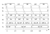
- FIG. 4 is a time chart showing the state change of the light emitting unit and the state change of signals and data of the image processing unit in the image processing apparatus according to the first embodiment of the present invention.
- FIG. 5 is a diagram illustrating an example of a document.
- FIG. 1 is a configuration diagram of an image processing apparatus according to the first embodiment of the present invention.
- FIG. 2 is a block diagram of an image processing related device provided in the image processing apparatus according to the first embodiment of the present invention.
- FIG. 3 is a block diagram of an image processing unit included in the image processing apparatus according to the first embodiment of the present invention.
- FIG. 4 is a time chart showing the state change
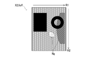
- FIG. 6 is a diagram illustrating an example of a two-dimensional image synthesized from an image data sequence obtained when the light emitting unit is turned on in the image processing apparatus according to the first embodiment of the present invention.
- FIG. 7 is a diagram illustrating an example of a two-dimensional image synthesized from an image data sequence obtained when the light emitting unit is turned off in the image processing apparatus according to the first embodiment of the present invention.
- FIG. 8 is a diagram illustrating an example of a two-dimensional image synthesized from the difference data sequence obtained in the image processing apparatus according to the first embodiment of the present invention.
- FIG. 9 is a block diagram of an image processing unit provided in the image processing apparatus according to the second embodiment of the present invention.
- the image processing apparatus 10 includes an image reading apparatus 1 and an image forming apparatus 2. Further, the image processing apparatus 10 also includes an information processing unit 8 and an operation display unit 80 that are common to the image reading apparatus 1 and the image forming apparatus 2.
- the image processing apparatus 10 is a copier, a printer or facsimile having a copier function, or a multi-function machine having a plurality of image processing functions including an image reading function.
- the image reading apparatus 1 includes a transparent document table 13, an image scanning unit 11, and a document table cover 12.
- An ADF (Auto Document Feeder) 120 is incorporated in the document table cover 12.
- the manuscript table 13 is a portion on which a manuscript 90 that is an image reading object is placed.
- the document table 13 is called platen glass.
- the document table cover 12 is supported by the casing 100 of the image processing apparatus 10 so as to be rotatable between a closed position that covers the document table 13 and an open position that releases the document table 13.
- the image scanning unit 11 includes a moving unit 111 including a light emitting unit 112, an optical system 113 such as a mirror and a lens, an image sensor 114, and the like.
- a moving unit 111 including a light emitting unit 112, an optical system 113 such as a mirror and a lens, an image sensor 114, and the like.
- an optical system 113 such as a mirror and a lens
- an image sensor 114 and the like.
- one direction in the horizontal plane and a direction perpendicular thereto are referred to as a main scanning direction R1 and a sub-scanning direction R2, respectively.
- the light emitting unit 112 is a light source that irradiates light toward the document 90 placed on the transparent document table 13.
- the light emitting unit 112 irradiates the document 90 with the strip-shaped light along the main scanning direction R ⁇ b> 1 through the document table 13.
- the light emitting unit 112 is an LED array including a plurality of light emitting diodes arranged along the main scanning direction R1. It is also conceivable that the light emitting unit 112 is a straight tubular fluorescent lamp along the main scanning direction R1.
- the optical system 113 includes a mirror and a lens for guiding the emitted light from the linear region along the main scanning direction R1 on the document table 13 to the light receiving unit of the image sensor 114.
- the emitted light from the linear region on the document table 13 includes the emitted light from the document 90 and the emitted light from the region outside the document.
- the light emitting unit 112 is turned on, the light emitted from the original 90 is reflected light of the light emitted from the light emitting unit 112 irradiated on the original 90.
- the emitted light from the outside region of the document is emitted light from the inner surface of the document table cover 12.
- the inner surface of the document table cover 12 is along the surface of the document table 13.
- the radiated light from the outside region of the document is external light incident on the document table 13 from above the document table 13.
- This external light causes a noise image in the area outside the document in the image read by the image reading apparatus 1.
- the image sensor 114 detects the amount of light emitted from the linear region along the main scanning direction R1 on the document table 13 for each pixel, and outputs the detected light amount data of each pixel as an image data string of the linear region. It is a sensor.
- the image sensor 114 may be a CCD (Charge-Coupled Device) 114.
- the image sensor 114 outputs an image data string corresponding to the detected light amount for each pixel in the linear region.
- the image data string includes data of a plurality of pixels that are partitioned regions in the main scanning direction R1 in the linear region.
- the image data string output by the image sensor 114 is referred to as a primary image data string X0.
- the moving unit 111 supports a part of the light emitting unit 112 and the optical system 113 and moves along the sub-scanning direction R2. Thereby, the position in the sub-scanning direction R ⁇ b> 2 of the linear region that is the light irradiation target of the light emitting unit 112 is changed.
- the linear region irradiated with light from the light emitting unit 112 is also a target for detecting the amount of emitted light by the image sensor 114.
- the image scanning unit 11 detects the amount of light emitted from the linear region along the main scanning direction R1 on the document table 13 for each pixel.
- the original 90 is scanned along the scanning direction R2.
- a contact image sensor in which the light emitting unit 112, the image sensor 114, and the lens are integrated may be employed in the image scanning unit 11.
- the contact image sensor is supported by the moving unit 111.
- the ADF 120 conveys the document 90 set on the document tray 121 to the discharge tray 123 via the image reading position by a plurality of rotating conveyance rollers 122. At that time, the image scanning unit 11 reads an image of the document 90 in a state where the moving unit 111 is stopped at the image reading position.
- the image reading apparatus 1 also includes a document sensor 801 and a cover sensor 802.
- the document sensor 801 is a sensor that detects whether or not the document 90 is set on the document tray 121.
- the cover sensor 802 is a sensor that detects whether or not the document table cover 12 is closed.
- the image forming apparatus 2 is an apparatus that forms an image corresponding to the image data string output from the image reading apparatus 1 on the recording sheet 9.
- the recording sheet 9 is a sheet-like image forming medium such as paper, coated paper, postcard, envelope, and OHP sheet.
- the image forming apparatus 2 includes a sheet conveying unit 3, an image forming unit 4, an optical scanning unit 5, a fixing unit 6, and the like.
- An image forming apparatus 2 shown in FIG. 1 is an electrophotographic image forming apparatus. It is also conceivable that the image forming apparatus 2 is an image forming apparatus of another method such as an ink jet method.
- the sheet delivery unit roller 31 sends the recording sheet 9 from the sheet storage unit 30 to the sheet transport path 300. Further, the sheet conveyance roller 32 conveys the recording sheet 9 along the sheet conveyance path 300. Further, the discharge roller 33 discharges the recording sheet 9 after image formation from the exit of the sheet conveyance path 300 onto the discharge tray 101.
- the image forming unit 4 forms an image on the surface of the recording sheet 9 moving on the sheet conveyance path 300.
- the image forming unit 4 includes a drum-shaped photoreceptor 41, a charging unit 42, a developing unit 43, a transfer unit 45, a cleaning unit 47, and the like.
- the photoconductor 41 is an example of an image carrier.
- the photosensitive member 41 rotates, and the charging unit 42 charges the surface of the photosensitive member 41 uniformly. Further, an electrostatic latent image is written on the surface of the photoreceptor 41 charged by the optical scanning unit 5 scanning the laser beam. Further, the developing unit 43 supplies the developer to the photosensitive member 41 to develop the electrostatic latent image into the image of the developer.
- the developer is supplied to the developing unit 43 from a developer supply unit (not shown).
- the transfer unit 45 transfers the developer image on the surface of the photosensitive member 41 to the recording sheet 9 moving on the sheet conveyance path 300.
- the cleaning unit 47 removes the developer remaining on the surface of the photoreceptor 41.
- the fixing unit 6 sandwiches the recording sheet 9 on which an image is formed between a fixing roller 61 including a heater such as a halogen heater and a pressure roller 62, and sends the recording sheet 9 to a subsequent process. As a result, the fixing unit 6 heats the image that is the image of the developer on the recording sheet 9 and fixes the image on the recording sheet 9.
- the information processing unit 8 displays an operation menu or the like on the operation display unit 80. Furthermore, the information processing unit 8 performs image processing on an image input through the image reading device 1. Further, the information processing unit 8 controls various electric devices included in the image processing apparatus 10 based on input information input through the operation display unit 80 and detection results of various sensors including the document sensor 801 and the cover sensor 802. .
- the information processing unit 8 includes an MPU (Micro Processor Unit) 81, a storage unit 82, a signal interface 83, a light emission control unit 84, an image processing unit 85, a laser control unit 86, and the like.
- MPU Micro Processor Unit
- the MPU 81 is a processor that executes various arithmetic processes.
- the storage unit 82 is a nonvolatile storage unit in which information such as programs Pr1 to Pr3 for causing the MPU 81 to execute various processes is stored in advance. Furthermore, the storage unit 82 is also a storage unit in which various information can be read and written by the MPU 81.
- the information processing unit 8 comprehensively controls the image processing apparatus 10 by the MPU 81 executing various programs Pr1 to Pr3 stored in the storage unit 82 in advance.
- the signal interface 83 is an interface circuit that relays signal exchange between the MPU 81 and the sensors, control target devices, and the like.
- the MPU 81 inputs detection signals (measurement signals) from various sensors such as the document sensor 801 and the cover sensor 802 via the signal interface 83. Further, the MPU 81 outputs a control signal to the control target device via the signal interface 83.
- the light emission control unit 84 controls the light emitting unit 112 of the image scanning unit 11 to turn on or off the light emitting unit 112.
- the image processing unit 85 inputs image data obtained through the image scanning unit 11 and executes image processing.
- the laser control unit 86 inputs the recording image data sequence output from the image processing unit 85, and adjusts the amount of laser light output from the optical scanning unit 5 in accordance with the density of each pixel indicated by the recording image data sequence. To do.
- the document 90 may be scanned by the image scanning unit 11 with the document table cover 12 being opened.
- a noise image caused by external light such as room illumination entering the image sensor 114 tends to appear in the document outside area.
- the information processing unit 8 in the present embodiment has a configuration for avoiding a phenomenon in which a noise image appears in the area outside the original document due to the influence of the external light by simpler processing.
- the light emission control unit 84 performs blinking control that causes the light emission unit 112 to blink while the image scanning unit 11 scans the document 90.
- the light emission control unit 84 is an example of a light emission control unit.
- the light emission control unit 84 sets the light emitting unit 112 in advance while the image scanning unit 11 scans the document 90.
- the blinking control for blinking at a cycle is executed.
- the operation mode signal Md is a signal representing the closed scanning mode
- the light emission control unit 84 keeps the light emitting unit 112 lit while the image scanning unit 11 scans the document 90.
- the open scanning mode is an operation mode in which scanning of the document 90 on the document table 13 is executed on the assumption that the document table cover 12 is opened.
- the closed scanning mode is an operation mode in which the document 90 on the document table 13 is scanned assuming that the document table cover 12 is closed.
- the MPU 81 sets the operation mode signal Md according to an operation on the operation display unit 80 by the user by executing the first operation mode setting program Pr1.
- the MPU 81 automatically sets the operation mode signal Md depending on whether the detection results of the document sensor 801 and the cover sensor 802 satisfy a predetermined open scanning mode condition. In this case, the MPU 81 automatically sets the operation mode signal Md by executing the second operation mode setting program Pr2.
- the open scanning mode condition is that the document sensor 801 and the cover sensor 802 detect a state in which the document 90 is not set on the document tray 121 and the cover sensor 802 is not closed.
- the MPU 81 detects that a copy execution operation has been performed on the operation display unit 80 in a state where the open scan mode condition is satisfied, the MPU 81 sets the operation mode signal Md to the open scan mode state. In other cases, the operation mode signal Md is set to the closed scanning mode.
- the image processing unit 85 includes a line buffer 852, a subtraction unit 853, a sampling unit 855, and a timing adjustment unit 857. Furthermore, the image processing unit 85 in the present embodiment also includes a preprocessing unit 851, a data selection unit 854, and a postprocessing unit 856.
- the image processing unit 85 may be configured by an ASIC (Application Specific Integrated Circuit) or a DSP (Digital Signal Pocessor).
- the pre-processing unit 851 performs known image correction processing such as shading correction and gamma correction on the primary image data sequence X0, and outputs a secondary image data sequence X1 that is a corrected image data sequence.
- the line buffer 852 is a buffer memory that temporarily stores image data sequences sequentially obtained through the image scanning unit 11 that is scanning the original 90 until the next new image data sequence is obtained.
- the line buffer 852 temporarily stores the secondary image data sequence X1 sequentially obtained through the image scanning unit 11 and the preprocessing unit 851.
- the subtracting unit 853 subtracts the other one from a predetermined one of the latest secondary image data sequence X1 obtained through the image scanning unit 11 and the previous secondary image data sequence X2 stored in the line buffer 852.
- the subtraction data string Y1 which is the result is sequentially generated.
- the subtraction unit 853 in the present embodiment calculates the subtraction data string Y1 by subtracting the secondary image data string X2 one time before from the latest secondary image data string X1.
- the image sensor 114 outputs the primary image data string X0 every time the light emitting unit 112 is switched between the on state and the off state. More specifically, the image sensor 114 outputs the primary image data string X0 corresponding to the light reception amount immediately before the state according to the timing of the state change of the shift gate signal Gs supplied from the timing adjustment unit 857. Accordingly, the primary image data string X0 in the lighting state and the primary image data string X0 in the unlit state are sequentially output from the image sensor 114.
- the timing adjustment unit 857 generates a shift gate signal Gs for causing the image sensor 114 to output the primary image data string X0 every time the light emitting unit 112 is switched between the lighting state and the extinguishing state, and outputs it to the image sensor 114.
- the timing adjustment unit 857 generates the shift gate signal Gs in which the state change occurs at a half cycle of the blinking cycle of the light emitting unit 112.
- the image sensor 144 alternately outputs the primary image data string X0 in the lighting state and the primary image data string X0 in the unlit state in synchronization with the state change of the shift gate signal Gs.
- the image processing unit 85 synchronizes with the shift gate signal Gs and the lighting-time image data sequence Xon that is the secondary image data sequence X1 when the light emitting unit 112 is in the lighting state. Then, the off-time image data sequence Xoff, which is the secondary image data sequence X1 when the light emitting unit 112 is in the off state, is alternately obtained.
- the secondary image data sequence X2 output from the line buffer 852 is the image data in the unlit state. Is a column.
- the secondary image data sequence X2 output from the line buffer 852 is the image in the lit state. It is a data string.
- the subtracting unit 853 changes the secondary image data sequence X1 one time before in the extinguishing state from the latest secondary image data sequence X1 in the lighting state.
- the result of the subtraction and the result of subtracting the secondary image data sequence X1 immediately before in the lighting state from the latest secondary image data sequence X1 in the unlit state are alternately generated.
- the result of subtracting the secondary image data sequence X1 one time before in the lighting state from the secondary image data sequence X1 in the extinguished state is shown as a first subtraction data sequence Xoff-on.
- a result obtained by subtracting the secondary image data string X1 one time before in the unlit state from the secondary image data string X1 in the lit state is shown as a second subtracted data string Xon-off.
- the second subtraction data string Xon-off is referred to as a difference data string Ys.
- the difference data sequence generation unit sequentially acquires the secondary image data sequence X1 through the image scanning unit 11, and from the lighting-time image data sequence Xon obtained for each blinking cycle of the light emitting unit 112 to the unlit-time image data sequence Xoff.
- the difference data string Ys that is the result of subtracting is sequentially generated.
- the data selection unit 854 inputs two data strings, the latest subtraction data string Y1 and the latest secondary image data string X1, and selects one of the two data strings in accordance with the operation mode signal Md output from the MPU 81. Output.
- the data selection unit 854 selects and outputs the subtraction data string Y1.
- the data selection unit 854 selects and outputs the secondary image data string X1.
- the timing adjustment unit 857 generates a synchronization signal Ss synchronized with the blinking cycle of the light emitting unit 112 and supplies the synchronization signal Ss to the sampling unit 855.
- the sampling unit 855 samples data in synchronization with the synchronization signal Ss.
- the timing adjustment unit 857 generates the synchronization signal Ss based on the light emission control signal Le that controls blinking of the light emitting unit 112.
- the light emission control signal Le is output from the light emission control unit 84.
- the sampling unit 855 synchronizes with the blinking cycle of the light emitting unit 112, and the difference data sequence from the two types of subtraction data sequence Y1 sequentially calculated by the subtraction unit 853. Sample Ys.
- the sampling unit 855 When the operation mode signal Md is in the closed scanning mode, the sampling unit 855 outputs the input secondary image data string X1 as it is without sampling.
- the post-processing unit 856 performs a predetermined adjustment process on the difference data sequence Ys or the secondary image data sequence X1 output from the sampling unit 855, and a recording image data sequence Yd that is a data sequence after the adjustment process. Is generated.
- the recording image data sequence Yd generated by the post-processing unit 856 is used by the laser control unit 86 to adjust the amount of laser light in the optical scanning unit 5.
- the post-processing unit 856 converts the data of each pixel corresponding to the amount of emitted light from the linear region in the difference data sequence Ys or the secondary image data sequence X1 into data representing pixel density. To do. For example, it is conceivable that the data of each pixel in the difference data string Ys or the secondary image data string X1 is data of 256 gradations from 0 to 255. In this case, the post-processing unit 856 calculates the pixel density of 256 gradations by subtracting the data of each pixel input from 255 which is the maximum gradation value.
- the laser control unit 86 adjusts the amount of laser light output from the optical scanning unit 5 in accordance with the density of each pixel indicated by the recording image data string Yd output from the image processing unit 85.
- the image forming apparatus 2 forms an image on the recording sheet 9 according to the difference data string Ys sequentially generated by the image reading apparatus 1.
- the operation mode signal Md is in the closed scanning mode, the image forming apparatus 2 forms an image corresponding to the secondary image data string X1 on the recording sheet 9.
- the image scanning unit 11 includes a plurality of image sensors 114 having different colors of light to be detected.
- the image processing unit 85 includes a plurality of preprocessing units 851, a plurality of line buffers 852, a plurality of subtraction units 853, a plurality of sampling units 855, and a plurality of postprocessing units 856 respectively corresponding to different color image data.
- the image reading apparatus 1 is an apparatus capable of reading a color image
- the image forming apparatus 2 includes a plurality of image forming units 4 corresponding to different color developers.
- each of the image forming units 4 transfers an image to an intermediate transfer belt (not shown), and the image on the intermediate transfer belt is transferred to the recording sheet 9.
- the light emission control unit 84 executes the light emission control process of blinking the light emitting unit 112 that emits light toward the original 90 placed on the original table 13. Further, the image scanning unit 11 detects, for each pixel, the amount of light emitted from the linear region along the main scanning direction R1 when the light emitting unit 112 is in the on state and in the off state. At the same time, an image scanning step of scanning the document 90 along the sub-scanning direction R2 is executed.
- the image processing unit 85 executes an image data sequence acquisition step of sequentially acquiring the secondary image data sequence X1 corresponding to the detected light quantity for each pixel of the linear region through the step executed by the image scanning unit 11. Further, the image processing unit 85 switches from the on-time image data sequence Xon to the off-time image data sequence Xoff of the two sets of image data sequences Xon and Xoff obtained for each blinking cycle of the light emitting unit 112 by the image data sequence acquisition step.
- a difference data string generation step for sequentially generating a difference data string Ys that is a result of subtracting.
- FIG. 5 is a diagram illustrating an example of the document 90.
- FIGS. 6 to 8 show two-dimensional composites obtained from respective data strings obtained when the document 90 on the document table 13 is scanned in the open scanning mode in the image processing apparatus 10 with the document table cover 12 opened. Images are shown.
- FIG. 6 is a diagram illustrating an example of a two-dimensional image synthesized from the secondary image data sequence X1 obtained when the light emitting unit 112 is turned on.
- FIG. 7 is a diagram illustrating an example of a two-dimensional image synthesized from the secondary image data sequence X1 obtained when the light emitting unit 112 is turned off.
- FIG. 8 is a diagram illustrating an example of a two-dimensional image synthesized from the difference data string.
- One of the two documents 90 is a document in which an opening 900 is partially formed.
- a two-dimensional image obtained by combining the lighting image data sequence Xon along the sub-scanning direction R2 is, for example, as shown in FIG. It becomes an image.
- the image of the lighting-on image data string Xon is an image including two original 90 images and an image outside the original area.
- the image of the outside area of the document includes a noise image Ng including an image of outside light and a shadow image of an object that blocks outside light.
- the image of the image data sequence Xoff when the light is off is an image including the shadow image of the two originals 90 and the image of the area outside the original.
- the images in the outside-document region in the on-image data sequence Xon and the off-image data sequence Xoff are substantially the same image.
- an image based on the difference data string Ys obtained by subtracting the unlit image data string Xoff corresponding to FIG. 7 from the lit image data string Xon corresponding to FIG. 6 is an image as shown in FIG.
- the image of the difference data string Ys includes two images of the original 90 and a substantially uniform image outside the original from which the noise image Ng has been removed.
- Each pixel data of the document area in the difference data string Ys is data corresponding to the emitted light amount in the range from the intermediate level to the maximum level.
- each pixel data of the area outside the document in the difference data string Ys is data corresponding to the minimum amount of emitted light, that is, data of approximately maximum density.
- the image processing unit 85 obtains the difference data sequence Ys from which the noise image Ng has been removed by a very simple process of subtracting the latest secondary image data sequence X1 and the secondary image data sequence X2 of the previous time. To derive. At that time, the image processing unit 85 does not need to perform image processing with a relatively high calculation load such as edge detection processing for specifying the document region from the image density data for each linear region.
- the image processing apparatus 10 is employed when the document 90 is scanned with the document table cover 12 opened, a phenomenon in which the noise image Ng appears in the document outside region due to the influence of external light is more likely to occur. This can be avoided by simple processing.
- the line buffer 852, the subtraction unit 853, the sampling unit 855, and the like can be realized by inexpensive elements with low power consumption.
- the image processing unit 85A is an application example of the image processing unit 85 of the image processing apparatus 10.
- FIG. 9 is a block diagram of the image processing unit 85A.
- the same components as those shown in FIG. 3 are denoted by the same reference numerals.
- differences from the image processing unit 85 in the image processing unit 85A will be described.
- the image processing unit 85A has a configuration in which a background replacement unit 858 is added to the configuration of the image processing unit 85.
- the background replacement unit 858 executes background replacement processing for replacing data satisfying a predetermined replacement condition in the difference data string Ys generated by the subtraction unit 853 with one preset background data.
- the replacement condition includes a condition that the pixel value falls below a preset lower limit value.
- the pixel value is a value of each pixel included in the difference data string Ys.
- the data selection unit 854 inputs two data strings of the latest subtraction data string Y1 and the latest secondary image data string X1, and in accordance with the operation mode signal Md, Select one to output.
- the sampling unit 855 includes two types of subtraction units 853 that sequentially calculate in synchronization with the blinking cycle of the light emitting unit 112 when the operation mode signal Md is in the open scanning mode.
- the difference data string Ys is sampled from the subtraction data string Y1.
- each pixel data of the document area in the difference data string Ys is data corresponding to the emitted light amount in a range from the intermediate level to the maximum level.
- each pixel data of the area outside the document in the difference data string Ys is data corresponding to the substantially minimum amount of emitted light.
- each pixel data in the area outside the original can be replaced with arbitrary uniform data.
- the MPU 81 sets the background data in accordance with a user operation on the operation display unit 80 by executing the background data setting program Pr3.
- the image processing unit 85A includes a plurality of pre-processing units 851, a plurality of line buffers 852, a plurality of subtraction units 853, a plurality of sampling units 855, and a plurality of post-processing units 856 respectively corresponding to image data of different colors.
- the background replacement unit 858 executes the background replacement process for the difference data string Ys for each color. In this case, it is conceivable that the background data of the same gradation or the background data of a different gradation is set for the difference data string Ys of each color.
- the replacement condition is that the pixel value is lower than the lower limit value and the pixel values including the pixel and lower than the lower limit value continue for a predetermined number or more in the main scanning direction R1.
- the replacement condition includes that a plurality of the pixel data below the lower limit value is continuous, the background replacement unit 858 replaces the pixel data in the document area with the background data. Can be prevented.
- the operation mode signal Md when the operation mode signal Md is in the open scanning mode, the operation mode signal Md is in the sub scanning direction R2 more than when the operation mode signal Md is in the closed scanning mode. It is conceivable that the scanning speed of the image scanning unit 11, that is, the moving speed of the moving unit 111 is set to a low speed. Thereby, it can be avoided that the image resolution in the sub-scanning direction R2 by the image scanning unit 11 in the open scanning mode is reduced to half of the image resolution in the closed scanning mode.
- the state in which the operation mode signal Md indicates the open scanning mode is an operation state in which the light emitting unit 112 blinks while the image scanning unit 11 is scanning.
- the state in which the operation mode signal Md indicates the closed scanning mode is an operation state in which the light emitting unit 112 continues to be lit while the image scanning unit 11 is scanning.
- the image scanning unit 11 when the operation mode signal Md is in the open scanning mode, the image scanning unit 11 performs the sub-scanning direction more than when the operation mode signal Md is in the closed scanning mode. It is also conceivable to shorten the light amount detection cycle of the linear region in R2, that is, the cycle of the light emission control signal Le. Thereby, it can be avoided that the image resolution in the sub-scanning direction R2 by the image scanning unit 11 in the open scanning mode is reduced to half of the image resolution in the closed scanning mode. Furthermore, it can be avoided that the scanning time of the image scanning unit 11 becomes long.
- the processing of the image processing units 85 and 85A shown above is realized by a processor that executes a computer program.
- the MPU 81 or another MPU for image processing executes processing equivalent to the processing of the image processing units 85 and 85A by executing a program stored in the storage unit 82 in advance.
- the image reading apparatus, the image processing apparatus, and the image reading method according to the present invention can be freely combined with or within the scope of the inventions described in the claims. Further, the present invention can be configured by appropriately modifying or omitting some of the application examples.
Landscapes
- Engineering & Computer Science (AREA)
- Multimedia (AREA)
- Signal Processing (AREA)
- Facsimile Scanning Arrangements (AREA)
- Image Input (AREA)
- Optical Systems Of Projection Type Copiers (AREA)
- Light Sources And Details Of Projection-Printing Devices (AREA)
Abstract
Description
まず、図1,2を参照しつつ第1実施形態に係る画像処理装置10の構成について説明する。画像処理装置10は、画像読取装置1および画像形成装置2を備える。さらに、画像処理装置10は、画像読取装置1および画像形成装置2に共通の情報処理部8および操作表示部80も備える。
本実施形態における発光制御部84は、画像走査部11が原稿90を走査中に発光部112を点滅させる点滅制御を実行する。なお、発光制御部84は発光制御部の一例である。
次に、図3,4を参照しつつ、画像処理部85について説明する。図3が示すように、画像処理部85は、ラインバッファー852、減算部853、サンプリング部855およびタイミング調整部857を備える。さらに、本実施形態における画像処理部85は、前処理部851、データ選択部854および後処理部856も備える。例えば、画像処理部85が、ASIC(Application Specific Integrated Circuit)またはDSP(Digital Signal Pocessor)などによって構成されることが考えられる。
続いて、図5~8を参照しつつ、画像処理装置10が実行する画像処理によって得られる具体的な二次元画像の一例について説明する。図5は、原稿90の一例を示す図である。図6~8は、画像処理装置10において、原稿台カバー12が開かれた状態で原稿台13上の原稿90が前記開走査モードで走査されたときに得られる各データ列から合成した二次元画像を示す。
次に、図9を参照しつつ、本発明の第2実施形態に係る画像形成装置が備える画像処理部85Aについて説明する。画像処理部85Aは画像処理装置10の画像処理部85の応用例である。
以上に示された画像処理部85,85Aにおいて、動作モード信号Mdが前記開走査モードの状態である場合に、動作モード信号Mdが前記閉走査モードの状態である場合よりも副走査方向R2における画像走査部11の走査速度、即ち、移動ユニット111の移動速度が遅い速度に設定されることが考えられる。これにより、前記開走査モードにおける画像走査部11による副走査方向R2の画像解像度が、前記閉走査モードにおける画像解像度の半分にまで低下することを回避できる。
Claims (6)
- 透明の原稿台に載置された原稿に向けて光を照射する発光部を点滅させる発光制御部と、
前記発光部が点灯状態であるときと消灯状態であるときとの各々において前記原稿台における主走査方向に沿う線状領域からの放出光の光量を画素ごとに検出しつつ前記主走査方向に直交する副走査方向に沿って前記原稿を走査する画像走査部と、
前記画像走査部を通じて前記線状領域の各画素についての検出光量に相当する画像データ列を順次取得し、前記発光部の点滅周期ごとに得られる2組の前記画像データ列のうちの前記点灯状態における前記画像データ列から前記消灯状態における前記画像データ列を減算した結果である差分データ列を順次生成する差分データ列生成部と、を備える画像読取装置。 - 前記差分データ列における、画素値が予め設定された下限値を下回るという条件を含む置換条件を満たすデータを一の背景データに置換する背景置換部をさらに備える、請求項1に記載の画像読取装置。
- 前記置換条件は、前記下限値を下回る前記画素値が前記主走査方向において予め定められた数以上連続しているという条件をさらに含む、請求項2に記載の画像読取装置。
- 前記差分データ列生成部は、
前記画像走査部を通じて順次得られる前記線状領域の前記画像データ列を次の前記画像データ列が得られるまで一時記憶するラインバッファーと、
前記画像走査部を通じて得られる最新の前記画像データ列および前記ラインバッファーに記憶された1回前の前記画像データ列のうちの予め定められた一方から他方を減算した結果である減算データ列を順次生成する減算部と、
前記発光部の点滅周期に同期して、前記減算部が順次算出する前記減算データ列から前記差分データ列をサンプリングするサンプリング部と、を備える請求項1に記載の画像読取装置。 - 請求項1に記載の画像読取装置と、
前記画像読取装置により順次生成される前記差分データ列に応じた画像を記録シートに形成する画像形成装置と、を備える画像処理装置。 - 透明の原稿台に載置された原稿に向けて光を照射する発光部を点滅させる工程と、
前記発光部が点灯状態であるときと消灯状態であるときとの各々において前記原稿台における主走査方向に沿う線状領域からの放出光の光量を画素ごとに検出しつつ前記主走査方向に直交する副走査方向に沿って前記原稿を走査する工程と、
前記原稿を走査する工程を通じて前記線状領域の各画素についての検出光量に相当する画像データ列を順次取得し、前記発光部の点滅周期ごとに得られる2組の前記画像データ列のうちの前記点灯状態における前記画像データ列から前記消灯状態における前記画像データ列を減算した結果である差分データ列を順次生成する工程と、を含む画像読取方法。
Priority Applications (2)
| Application Number | Priority Date | Filing Date | Title |
|---|---|---|---|
| US15/562,157 US10291819B2 (en) | 2015-03-31 | 2016-03-25 | Image reading device with noise removal when cover is open |
| JP2017509887A JP6512285B2 (ja) | 2015-03-31 | 2016-03-25 | 画像読取装置、画像処理装置、画像読取方法 |
Applications Claiming Priority (2)
| Application Number | Priority Date | Filing Date | Title |
|---|---|---|---|
| JP2015-071033 | 2015-03-31 | ||
| JP2015071033 | 2015-03-31 |
Publications (1)
| Publication Number | Publication Date |
|---|---|
| WO2016158713A1 true WO2016158713A1 (ja) | 2016-10-06 |
Family
ID=57004282
Family Applications (1)
| Application Number | Title | Priority Date | Filing Date |
|---|---|---|---|
| PCT/JP2016/059538 Ceased WO2016158713A1 (ja) | 2015-03-31 | 2016-03-25 | 画像読取装置、画像処理装置、画像読取方法 |
Country Status (3)
| Country | Link |
|---|---|
| US (1) | US10291819B2 (ja) |
| JP (1) | JP6512285B2 (ja) |
| WO (1) | WO2016158713A1 (ja) |
Cited By (1)
| Publication number | Priority date | Publication date | Assignee | Title |
|---|---|---|---|---|
| US12353184B2 (en) * | 2021-08-05 | 2025-07-08 | Mitsubishi Electric Corporation | Programmable controller, programmable controller system, and recording medium |
Families Citing this family (1)
| Publication number | Priority date | Publication date | Assignee | Title |
|---|---|---|---|---|
| JP7640708B2 (ja) * | 2021-08-06 | 2025-03-05 | 株式会社Pfu | 画像処理装置、画像処理方法、及びプログラム |
Citations (3)
| Publication number | Priority date | Publication date | Assignee | Title |
|---|---|---|---|---|
| JPH09135330A (ja) * | 1995-11-10 | 1997-05-20 | Ricoh Co Ltd | 光走査型原稿サイズセンサ |
| JP2013102425A (ja) * | 2011-10-21 | 2013-05-23 | Canon Inc | 画像処理装置および原稿領域判定方法 |
| JP2013115499A (ja) * | 2011-11-25 | 2013-06-10 | Kyocera Document Solutions Inc | 画像読取装置、画像形成装置、画像読取方法 |
Family Cites Families (2)
| Publication number | Priority date | Publication date | Assignee | Title |
|---|---|---|---|---|
| JP5531464B2 (ja) * | 2009-06-29 | 2014-06-25 | セイコーエプソン株式会社 | 画像処理プログラム、画像処理装置および画像処理方法 |
| JP5784467B2 (ja) | 2011-11-18 | 2015-09-24 | 京セラドキュメントソリューションズ株式会社 | 画像形成装置 |
-
2016
- 2016-03-25 US US15/562,157 patent/US10291819B2/en not_active Expired - Fee Related
- 2016-03-25 WO PCT/JP2016/059538 patent/WO2016158713A1/ja not_active Ceased
- 2016-03-25 JP JP2017509887A patent/JP6512285B2/ja active Active
Patent Citations (3)
| Publication number | Priority date | Publication date | Assignee | Title |
|---|---|---|---|---|
| JPH09135330A (ja) * | 1995-11-10 | 1997-05-20 | Ricoh Co Ltd | 光走査型原稿サイズセンサ |
| JP2013102425A (ja) * | 2011-10-21 | 2013-05-23 | Canon Inc | 画像処理装置および原稿領域判定方法 |
| JP2013115499A (ja) * | 2011-11-25 | 2013-06-10 | Kyocera Document Solutions Inc | 画像読取装置、画像形成装置、画像読取方法 |
Cited By (1)
| Publication number | Priority date | Publication date | Assignee | Title |
|---|---|---|---|---|
| US12353184B2 (en) * | 2021-08-05 | 2025-07-08 | Mitsubishi Electric Corporation | Programmable controller, programmable controller system, and recording medium |
Also Published As
| Publication number | Publication date |
|---|---|
| JP6512285B2 (ja) | 2019-05-15 |
| JPWO2016158713A1 (ja) | 2018-03-01 |
| US10291819B2 (en) | 2019-05-14 |
| US20180084152A1 (en) | 2018-03-22 |
Similar Documents
| Publication | Publication Date | Title |
|---|---|---|
| US10827101B2 (en) | Color inspection device to correct color readings of a color detection object using correction coefficients | |
| US11089177B2 (en) | Reading device, image forming apparatus, and image reading method | |
| JP5481436B2 (ja) | 画像読取装置及び画像形成装置 | |
| JP2008193677A (ja) | 画像形成装置およびその制御方法 | |
| JP6512285B2 (ja) | 画像読取装置、画像処理装置、画像読取方法 | |
| JP2012048009A (ja) | 画像形成装置 | |
| US8822908B2 (en) | Image scanner, image forming apparatus and dew-condensation determination method | |
| JP2016032219A (ja) | 画像読取装置、画像形成装置及び画像読取方法 | |
| JP6095634B2 (ja) | 画像読取装置、画像形成装置、画像読取方法 | |
| JP6369370B2 (ja) | 画像読取装置、画像処理装置、画像読取装置の制御方法 | |
| JP6369371B2 (ja) | 画像読取装置、画像処理装置、画像読取装置の制御方法 | |
| JP6314891B2 (ja) | 画像読取装置、画像処理装置、画像読取装置の制御方法 | |
| JP6369372B2 (ja) | 画像読取装置、画像処理装置、画像読取装置の制御方法 | |
| JP6369373B2 (ja) | 画像読取装置、画像処理装置、画像読取装置の制御方法 | |
| JP6358190B2 (ja) | 画像読取装置、画像処理装置、画像読取装置の制御方法 | |
| US9060148B2 (en) | Image reading device, image forming apparatus, and image reading method | |
| JP6477283B2 (ja) | 光電変換素子、画像読取装置、画像形成装置及び光電変換素子の制御方法 | |
| JP2018098728A (ja) | 画像読取装置、画像形成装置 | |
| JP6459997B2 (ja) | 画像処理装置、画像読取装置、異物画像領域検出方法 | |
| JP7070046B2 (ja) | 色検査装置、画像形成装置、色検査方法およびプログラム | |
| JP6197412B2 (ja) | 撮像装置、画像読取装置、画像形成装置、および撮像装置の駆動方法 | |
| JP6459996B2 (ja) | 画像処理装置、画像読取装置、異物画像領域検出方法 | |
| US20120099166A1 (en) | Image reading apparatus, image reading method, and image forming apparatus | |
| US20110286055A1 (en) | Reading apparatus, image forming apparatus and image reading control method | |
| JP2010220025A (ja) | 画像読取装置および画像形成装置 |
Legal Events
| Date | Code | Title | Description |
|---|---|---|---|
| 121 | Ep: the epo has been informed by wipo that ep was designated in this application |
Ref document number: 16772594 Country of ref document: EP Kind code of ref document: A1 |
|
| ENP | Entry into the national phase |
Ref document number: 2017509887 Country of ref document: JP Kind code of ref document: A |
|
| WWE | Wipo information: entry into national phase |
Ref document number: 15562157 Country of ref document: US |
|
| NENP | Non-entry into the national phase |
Ref country code: DE |
|
| 122 | Ep: pct application non-entry in european phase |
Ref document number: 16772594 Country of ref document: EP Kind code of ref document: A1 |