WO2016158591A1 - 車両用のシートスライド装置 - Google Patents
車両用のシートスライド装置 Download PDFInfo
- Publication number
- WO2016158591A1 WO2016158591A1 PCT/JP2016/059078 JP2016059078W WO2016158591A1 WO 2016158591 A1 WO2016158591 A1 WO 2016158591A1 JP 2016059078 W JP2016059078 W JP 2016059078W WO 2016158591 A1 WO2016158591 A1 WO 2016158591A1
- Authority
- WO
- WIPO (PCT)
- Prior art keywords
- lower rail
- rail
- upper rail
- slide device
- seat slide
- Prior art date
- Legal status (The legal status is an assumption and is not a legal conclusion. Google has not performed a legal analysis and makes no representation as to the accuracy of the status listed.)
- Ceased
Links
Images





Classifications
-
- B—PERFORMING OPERATIONS; TRANSPORTING
- B60—VEHICLES IN GENERAL
- B60N—SEATS SPECIALLY ADAPTED FOR VEHICLES; VEHICLE PASSENGER ACCOMMODATION NOT OTHERWISE PROVIDED FOR
- B60N2/00—Seats specially adapted for vehicles; Arrangement or mounting of seats in vehicles
- B60N2/02—Seats specially adapted for vehicles; Arrangement or mounting of seats in vehicles the seat or part thereof being movable, e.g. adjustable
- B60N2/04—Seats specially adapted for vehicles; Arrangement or mounting of seats in vehicles the seat or part thereof being movable, e.g. adjustable the whole seat being movable
- B60N2/06—Seats specially adapted for vehicles; Arrangement or mounting of seats in vehicles the seat or part thereof being movable, e.g. adjustable the whole seat being movable slidable
-
- B—PERFORMING OPERATIONS; TRANSPORTING
- B60—VEHICLES IN GENERAL
- B60N—SEATS SPECIALLY ADAPTED FOR VEHICLES; VEHICLE PASSENGER ACCOMMODATION NOT OTHERWISE PROVIDED FOR
- B60N2/00—Seats specially adapted for vehicles; Arrangement or mounting of seats in vehicles
- B60N2/02—Seats specially adapted for vehicles; Arrangement or mounting of seats in vehicles the seat or part thereof being movable, e.g. adjustable
- B60N2/04—Seats specially adapted for vehicles; Arrangement or mounting of seats in vehicles the seat or part thereof being movable, e.g. adjustable the whole seat being movable
- B60N2/06—Seats specially adapted for vehicles; Arrangement or mounting of seats in vehicles the seat or part thereof being movable, e.g. adjustable the whole seat being movable slidable
- B60N2/07—Slide construction
Definitions
- the present invention relates to a seat slide device for a vehicle.
- the lower rail of the seat slide device employed in the rear seat of a vehicle having three rows of seats is configured such that the front is lower than the rear.
- the lower rail of the front seat such as the driver's seat is configured such that the rear is lower than the front.
- the load required to operate the seat forward when adjusting the seat position forward and the seat required when adjusting the seat position backward are moved backward
- the load to operate is different.
- the seat slide device for vehicles of patent documents 1 is provided with a slide resistance adjustment mechanism.
- the slide resistance adjusting mechanism has a large number of protrusions provided on the lower rail, and a ball attached to the upper rail via a spring for resilient compression.
- the protrusion has an inclined surface and a resistance surface.
- the inclined surface is provided on the rear side in the upward direction of the seat in the ridge portion, and the resistance surface is provided on the front side in the upward direction of the sheet in the ridge portion.
- the resistance surface has a steeper slope than the sloped surface.
- the angle of the surface on which the ball contacts that is, the resistance that the ball receives from the surface varies depending on the direction in which the sheet is slid.
- An object of the present invention is to provide a seat slide device for a vehicle that is easy to adjust.
- a seat slide device for a vehicle comprises a lower rail, an upper rail supported by the lower rail so as to be relatively movable, and one of the lower rail and the upper rail biased. And a pressing member attached via the member.
- the pressing member always presses the other of the lower rail and the upper rail by the biasing force of the biasing member.
- the lower rail and the upper rail extend in a first direction.
- the pressing member diagonally presses the other of the lower rail and the upper rail such that a component force is generated in both the first direction and a second direction orthogonal to the first direction.
- the pressing direction of the pressing member is inclined with respect to the rail. Therefore, it is possible to make a difference in the load when the upper rail moves relative to the lower rail. Further, since the contact between the pressing member and the rail is always maintained by the biasing member, the load described above always acts when adjusting the seat position. Therefore, the load necessary for adjusting the seat position is stabilized, and the seat position can be easily adjusted.
- the biasing member is a spiral spring.
- the pressing member is a rotating member that is rotated by the biasing force of the spiral spring.
- the spiral spring and the rotating member are attached to one of the lower rail and the upper rail in a state in which the axial centers coincide with each other.
- the seat slide for a vehicle can be miniaturized.
- the lower rail is inclined such that one of its front and rear parts is higher than the other.
- the pressing member is attached to the upper rail, and presses the lower rail such that a component force along the downward direction of the lower rail is generated.
- a pair of the pressing members is provided.
- the pressing member is positioned equidistantly on both sides in the same direction from the center of the lower rail and the upper rail in the lateral direction, and presses the lower rail or the upper rail.
- the pair of pressing members are positioned equidistantly on both sides in the same direction from the center of the lower rail and the upper rail in the lateral direction and press the lower rail or the upper rail, the pressing places are increased and the pressing force is well balanced. It can be applied to the upper rail.
- the seat slide device for a vehicle includes a fixing member for attaching the pair of pressing members to one of the lower rail and the upper rail, and a support member rotatably supporting the pressing member. Further include.
- the pair of pressing members are configured to share one of the fixing member, one of the supporting members, and one of the biasing members.
- the pair of pressing members share one fixing member, one supporting member, and one biasing member, the number of parts can be reduced.
- the pressing member has a housing portion for housing the biasing member.
- the biasing member is housed and configured in the housing portion provided in the pressing member, the exposure of the biasing member can be suppressed as much as possible.
- the seat slide device for vehicles of the present invention is easy to adjust the position.
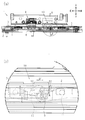
- (A) is a whole side view of a seat slide device of a 1st embodiment
- (b) is an enlarged drawing of the circled part of (a).
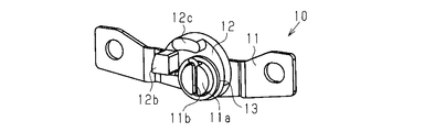
- (A) is a side view of the slide load adjustment mechanism of 1st Embodiment
- (b) is a top view of the slide load adjustment mechanism of 1st Embodiment.
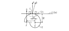
- the schematic diagram which shows the force which acts on the rotation member of 1st Embodiment.
- (A) is a whole top view of a seat slide device of a 2nd embodiment
- (b) is a whole side view of a seat slide device. Sectional drawing along the 9-9 line of FIG.8 (b) of the seat slide apparatus of 2nd Embodiment.
- the seat slide device 1 for a vehicle includes a lower rail 2 fixed to a vehicle floor, an upper rail 3 relatively displaceable to the lower rail 2, and a lock attached to the upper rail 3 And a mechanism 4.
- the lower rail 2 has a plurality of engagement holes 5 juxtaposed in the longitudinal direction of the lower rail 2.
- the lock mechanism 4 has an engagement claw 6 which is switched between a state of engaging with the engagement hole 5 (hereinafter referred to as a locked state) and a state of not engaged with the engagement hole 5 (hereinafter referred to as an unlocked state).
- the relative displacement of the upper rail 3 with respect to the lower rail 2 is restricted when the lock mechanism 4 is in the locked state, and the relative displacement of the upper rail 3 with respect to the lower rail 2 is permitted when the lock mechanism 4 is in the unlocked state.
- the configuration and operation of the lock mechanism 4 are well known techniques, and thus the detailed description thereof is omitted.
- the seat slide device 1 for a vehicle has a slide load adjusting mechanism 10.
- the slide load adjustment mechanism 10 is provided on each of the left and right sides of one upper rail 3.
- the slide load adjustment mechanism 10 attached to the left side of the upper rail 3 and the slide load adjustment mechanism 10 attached to the right side of the upper rail 3 are configured to be symmetrical in the left-right direction.
- the slide load adjustment mechanism 10 attached to the left side of the upper rail 3 will be described as a representative.
- the slide load adjusting mechanism 10 has a fixed member 11, a rotating member 12 as a pressing member, and a spiral spring 13 as a biasing member.
- the fixing member 11 is a plate member extending in the front-rear direction, and is fixed to the left side surface of the upper rail 3.
- the fixing member 11 has a cylindrical portion 11 a that protrudes leftward at the center on the left side surface thereof.
- the fixing member 11 also has a support portion 11 b which is formed at the tip of the cylindrical portion 11 a and supports one end of the spiral spring 13.
- the rotating member 12 is a fan-shaped plate material.
- the rotating member 12 has a mounting hole 12a located behind the center of the fan and having an inner diameter slightly larger than that of the cylindrical portion 11a.
- the rotating member 12 is attached to the fixing member 11 in a rotatable state by inserting the cylindrical portion 11 a into the mounting hole 12 a.
- the center of the mounting hole 12a is taken as the rotation center O.
- the rotating member 12 has a support portion 12b located forward of the center of the fan and protruding leftward.
- the support 12 b supports the end of the spiral spring 13 provided on the side opposite to the end supported by the support 11 b.
- the distance between the rotation center O and the central portion of the support portion 12b is taken as a length L.
- the rotating member 12 has a pressing portion 12c which is located above the center of the fan and protrudes leftward.
- the upper surface of the pressing portion 12 c is continuous with the outer periphery of the rotating member 12.
- the position of the pressing portion 12c is set so that the distance between the pressing portion 12c and the rotation center O is longer than the vertical distance between the lower surface of the upper wall 2a of the lower rail 2 and the rotation center O. It is set.
- the spiral spring 13 has an inner diameter slightly larger than the outer diameter of the cylindrical portion 11a.
- the spiral spring 13 is fixed to the support portion 11 b of the fixed member 11 at one end and the support portion 12 b of the rotation member 12 in a state where the spiral spring 13 is positioned further to the left of the rotation member 12 and is elastically compressed.
- the spiral spring 13 By attaching the spiral spring 13 to the fixed member 11, detachment of the rotating member 12 to the left is restricted.
- the rotating member 12 is urged clockwise by a spiral spring 13.
- the support portion 12 b is urged upward from the spiral spring 13 by the urging force Q.
- the biasing force Q for biasing the support portion 12 b is a resultant force of forces acting on the portion where the end portion of the spiral spring 13 and the support portion 12 b contact. Therefore, as shown in FIG. 5, for convenience, in the present embodiment, the following description will be made assuming that the biasing force Q acts on a point (biasing point F) whose distance from the rotation center O is L.
- the distance between the pressing portion 12c and the rotation center O is set to be longer than the distance between the lower surface of the upper wall 2a of the lower rail 2 and the rotation center O, so that the pressing portion 12c is , And the lower surface of the upper wall 2 a of the lower rail 2.
- a contact point between the pressing portion 12 c and the lower surface of the upper wall 2 a of the lower rail 2 is referred to as a contact point C.
- the distance between the pressing portion 12c and the rotation center O is set to be longer than the distance between the lower surface of the upper wall 2a of the lower rail 2 and the rotation center O. Located more forward than.
- a distance between the contact point C and the rotation center O in the front-rear direction is a length D1
- a distance between the contact point C and the rotation center O in the vertical direction is a length D2.
- the rotating member 12 always contacts the lower rail 2 at the contact point C. Therefore, when the upper rail 3 is relatively displaced with respect to the lower rail 2, the rotating member 12 acts as a so-called shoe brake that obtains a braking force by friction.
- the difference between the load (frictional force) P1 and P2 at the contact point C and the lower rail 2 has an opposite relationship.
- the difference between the loads (frictional forces) P1 and P2 in the front-rear direction of the upper rail 3 along the extending direction of the lower rail 2 and the component of the extending direction of the lower rail 2 acting on the sheet (upper rail 3) are offset. Therefore, the difference between the load for operating the seat forward when adjusting the seat position forward and the load for operating the seat backward when adjusting the seat position backward is reduced. be able to.
- the rotating member 12 always presses the lower surface of the upper wall 2 a of the lower rail 2 by the biasing force Q of the spiral spring 13.
- the distance between the pressing portion 12c and the rotation center O is set longer than the distance between the lower surface of the upper wall 2a of the lower rail 2 and the rotation center O.
- the contact point (contact point C) with the lower surface of the wall 2a is located forward of the rotation center O.
- the pressing direction of the rotating member 12 is oblique to the lower rail 2.
- the rotary member 12 and the spiral spring 13 are both attached to the upper rail 3 by inserting the cylindrical portion 11 a into the rotary member 12 and the spiral spring 13.
- the rotary member 12 and the spiral spring 13 utilize the cylindrical portion 11a having a common axis, and therefore, are smaller than in the case of adopting another structure.
- the seat slide device adopts the spiral spring 13 as the biasing member and the rotating member 12 as the pressing member.
- the following configuration may be employed.
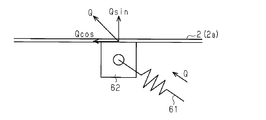
- the seat slide device employs a coil spring 61 as an urging member and a pressing portion 62 which does not rotate as a pressing member.
- One end (not shown) of the coil spring 61 is fixed to the upper rail 3, and the other end is fixed to the pressing portion 62.
- the pressing portion 62 always presses the lower rail 2 so that the biasing force Q of the coil spring 61 acts obliquely on the lower rail 2.
- the biasing force Q is decomposed into Qsin which is a vertical component of the lower rail 2 and Qcos which is an extension direction component.
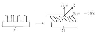
- the seat slide device may employ a member 71 that exhibits the functions of both the biasing member and the pressing member.
- the biasing force Q is the vertical direction component Qsin of the lower rail 2 and the extension direction component It is decomposed into Q cos. Therefore, the advantages shown in (1) and (2) of the above embodiment can be obtained.
- the seat slide device 1 when the seat slide device 1 is used for a seat configured such that the rear portion of the lower rail 2 is lower than the front portion, the difference between the load (frictional force) P1 and P2 in the front and rear direction is a gravity component Can be offset.
- the seat slide device 1 as the horizontal lower rail 2 instead of this, it is possible to provide a load difference between when the seat position is adjusted forward and when it is adjusted backward. As a result, it is possible to provide a seat slide device which is hard to be displaced forward.
- the slide load adjustment mechanism 10 is provided on the left and right sides of the upper rail 3 but may be provided on only one side. In the above embodiment, the slide load adjusting mechanism 10 is provided one by one on the left and right sides of the upper rail 3 but may be provided two or more on the left and right sides.
- the rotary member 12 abuts on the upper wall 2a of the lower rail 2, but may abut on a portion of the lower rail 2 other than the upper wall 2a.
- Second Embodiment a second embodiment of a seat slide device for a vehicle will be described according to the drawings.
- the main difference between the present embodiment and the first embodiment is only the aspect of the slide load adjustment mechanism. Therefore, for convenience of explanation, the same components as those in the first embodiment are denoted by the same reference numerals, and the description thereof is omitted.
- the seat slide device 1 for a vehicle of the present embodiment is provided with a slide load adjustment mechanism 20.
- One slide load adjustment mechanism 20 is provided for each upper rail 3.
- the slide load adjusting mechanism 20 includes a fixed member 21, two rotating members 22 and 23 as pressing members, a spiral spring (torsion spring) 24 as a biasing member, and a support. It has a pin 25 as a member and a nut 26.
- the fixing member 21 is a plate member extending in the front-rear direction, and is fixed to a portion where a lower portion of the upper rail 3 is partially cut away.
- the fixing member 21 is provided with a mounting hole 21 a through which the screw portion 25 a of the tip of the pin 25 is inserted.
- the mounting hole 21 a is located at the center of the upper rail 3 in the left-right direction.
- the two rotary members that is, the first and second rotary members 22 and 23 are fan-shaped members.
- the first rotating member 22 is disposed so as to protrude leftward with the pin 25 as a center when viewed from the rear side toward the front side, and the second rotating member 23 is disposed so as to project rightward in a similar situation.
- the first and second rotating members 22 and 23 respectively have mounting pieces 22a and 23a which are paired in the vertical direction, and mounting holes 22b and 23b through which the pins 25 are inserted are provided in the respective mounting pieces 22a and 23a. ing.
- a support shaft 25c between the screw 25a of the pin 25 and the head 25b is positioned in each of the mounting holes 22b and 23b.
- the distance W2 between the pair of mounting pieces 23a of the second rotating member 23 is set larger than the thickness in the vertical direction of the spiral spring 24, and the spiral spring 24 is an accommodating portion 27 formed between the pair of mounting pieces 23a.
- the distance W1 between the pair of attachment pieces 22a of the first rotation member 22 is set larger than the distance W2 between the pair of attachment pieces 23a of the second rotation member 23. That is, the pair of mounting pieces 22a of the first rotating member 22 and the pair of mounting pieces 23a of the second rotating member 23 are overlapped and combined so that the mounting pieces 22a are positioned outside the mounting pieces 23a in the vertical direction.
- the pins 25 are mounting holes 22b and 23b of the mounting pieces 22a and 23a and a mounting hole 24b of the winding portion 24a of the spiral spring 24. Is inserted. Thereafter, the screw portion 25 a of the pin 25 is inserted into the mounting hole 21 a of the fixing member 21, and the nut 26 is screwed in after being inserted.
- the first and second rotating members 22 and 23 and the spiral spring 24 are assembled between the fixed member 21 and the head 25 b of the pin 25, and each rotating member 22 is centered on the pin 25 (support shaft portion 25 c). , 23 can be rotated in the horizontal direction. That is, the center of the pin 25 is the rotation center O of each of the rotating members 22 and 23.
- end portions 24c and 24d extend from one end and the other end of the winding portion 24a of the spiral spring 24, respectively.
- the end portions 24 c and 24 d are latched to the first and second rotating members 22 and 23, and expand the respective rotating members 22 and 23 around the pin 25 (rotate from the front side to the rear side of the upper rail 3) Apply a biasing force).
- the first and second rotating members 22 and 23 have pressing portions 22c and 23c connected to the mounting pieces 22a and 23a and extending on the projecting side. End faces 22d, 23d on the radially outer side of the pressing portions 22c, 23c are arc-shaped, and each end face 22d, 23d is a straight line in the front-rear direction of the upper rail 3 passing through the rotation center O of the rotating members 22, 23 (center of pin 25). It has a line-symmetrical shape around.
- the distance from the rotation center O of the first and second rotating members 22 and 23 (the center of the pin 25) to the end faces 22d and 23d of the pressing portions 22c and 23c differs depending on the longitudinal position. That is, the arc shape of the end faces 22 d and 23 d is set to be shifted to the front side of the upper rail 3 with respect to the rotation center O. Therefore, as shown in FIG. 8A, the distance A from the rotation center O to the front end portions of the end surfaces 22d and 23d is larger than the distance B from the rotation center O to the rear end portions of the end surfaces 22d and 23d. That is, the distance from the rotation center O to the end surfaces 22 d and 23 d is set to increase as going from the rear to the front.
- the end faces 22 d and 23 d of the pressing portions 22 c and 23 c are in contact with the inner side surface of the side wall portion 2 b of the lower rail 2.
- the contact point C between the end faces 22 d and 23 d of the pressing parts 22 c and 23 c and the inner side face of the side wall 2 b of the lower rail 2 is set to be forward of the rotation center O of the rotating members 22 and 23.
- the end faces 22d and 23d of the pressing parts 22c and 23c of the rotating members 22 and 23 always contact the inner surface of the side wall 2b of the lower rail 2 diagonally at the contact point C, thereby the same control as in the first embodiment. Power (shoe brake) is obtained.
- the seat slide device 1 applies a larger load (frictional force) to the lower rail 2 by the slide load adjusting mechanism 20 when moving the upper rail 3 forward than when moving the upper rail 3 backward, the user of the vehicle It is easy to slide the seat backwards.
- the load (frictional force) of the upper rail 3 in the longitudinal direction along the extending direction of the lower rail 2 And the extension direction component of the lower rail 2 of the gravity acting on the seat (upper rail 3) is offset, so that the difference between the load of the forward operation of the seat and the load of the rearward operation of the seat can be reduced. it can.
- the pressing portions 22c and 23c of the first and second rotating members 22 and 23 are both sides in the same direction from the center in the left-right direction of the lower rail 2 (in this case, the rotation center O). And the lower rail 2 is pressed equidistantly. Therefore, the pressing position by the slide load adjustment mechanism 20 is increased, and the slide load adjustment mechanism 20 can apply a pressing force to the lower rail 2 in a well-balanced manner. Further, since the fixed member 21, the pin 25 and the spiral spring 24 can be configured as one for the two rotating members 22 and 23, the number of parts can be reduced. In addition, since the spiral spring 24 is housed in the housing portion 27, the exposure of the spring 24 is suppressed as much as possible.
- the configuration of the slide load adjustment mechanism 20 may be changed as appropriate.
- the modification of the slide load adjustment mechanism 10 of the first embodiment described immediately before the second embodiment may be combined with the slide load adjustment mechanism 20 of the second embodiment as appropriate.
Landscapes
- Engineering & Computer Science (AREA)
- Aviation & Aerospace Engineering (AREA)
- Transportation (AREA)
- Mechanical Engineering (AREA)
- Seats For Vehicles (AREA)
Abstract
車両用のシートスライド装置は、ロアレールと、ロアレールに相対移動可能に支持されるアッパレールと、ロアレール及びアッパレールのうちの一方に付勢部材を介して取り付けられる押圧部材とを含む。押圧部材は付勢部材の付勢力によりロアレール及びアッパレールのうちの他方を常時押圧する。ロアレール及びアッパレールは第1の方向に延びている。押圧部材は、第1の方向及び該第1の方向に直交する第2の方向の両方に分力が発生するようにロアレール及びアッパレールのうちの他方を斜めに押圧する。
Description
本発明は、車両用のシートスライド装置に関する。
従来、3列シートを有する車両の後部座席に採用されるシートスライド装置のロアレールは、前部が後部よりも低くなるように構成されている。一方で、ドライバー席などの前方の座席のロアレールは後部が前部よりも低くなるように構成されている。このように傾斜するロアレールを有する座席では、シート位置を前方に調整する場合に必要とされるシートを前方に操作する荷重と、シート位置を後方に調整する場合に必要とされるシートを後方に操作する荷重とが異なる。
特許文献1の車両用のシートスライド装置は、スライド抵抗調節機構を備える。当該スライド抵抗調節機構は、ロアレールに設けられる多数の突条部と、弾性圧縮するばねを介してアッパレール取り付けられるボールとを有する。突条部は傾斜面と抵抗面とを有する。傾斜面は突条部においてシートの上り方向後方側に設けられており、抵抗面は突条部においてシートの上り方向前方側に設けられている。抵抗面は傾斜面よりも急な傾斜を有している。スライド操作される際、ボールは突条部を乗り越える。この乗り越えの際、シートがスライド操作される方向により、ボールが接触する面の角度、すなわち面からボールが受ける抵抗が異なる。この関係を利用すれば、シートの上り方向のスライド操作に必要な荷重とシートの下り方向のスライド操作に必要な荷重とを等しく設定することができる。
ところで、特許文献1の車両用のシートスライド装置では、ボールが突条部を乗り越えた瞬間、ボールと突条部との間に抵抗がなくなる。すなわち、スライド操作全体では、スライド操作に必要な荷重が安定しないため、細かい位置調整がしにくい。
本発明の目的は、位置調整しやすい車両用のシートスライド装置を提供することにある。
上記目的を達成するため、本発明の一態様にかかる車両用のシートスライド装置は、ロアレールと、該ロアレールに相対移動可能に支持されるアッパレールと、前記ロアレール及び前記アッパレールのうちの一方に付勢部材を介して取り付けられる押圧部材とを含む。該押圧部材は前記付勢部材の付勢力により前記ロアレール及び前記アッパレールのうちの他方を常時押圧する。前記ロアレール及び前記アッパレールは第1の方向に延びている。前記押圧部材は、前記第1の方向及び該第1の方向に直交する第2の方向の両方に分力が発生するように前記ロアレール及び前記アッパレールのうちの他方を斜めに押圧する。
この構成によれば、押圧部材の押圧方向は、レールに対して傾斜する。これにより、ロアレールに対しアッパレールが相対移動する際の荷重に差を持たせることが可能となる。また、押圧部材とレールとの接触が付勢部材により常時維持されるので、上述した荷重は、シート位置を調整する際に常時作用する。したがって、シート位置の調整に必要な荷重が安定するので、シート位置を調整しやすい。
なお、従来のようにレールに突条部を多数設ける必要がないので、この構成は、従来と比較して製造にかかる工数も少ない。
好ましくは、前記付勢部材は、渦巻きスプリングである。前記押圧部材は、前記渦巻きスプリングの付勢力により回転する回転部材である。前記渦巻きスプリング及び前記回転部材は、軸心が互いに一致した状態で前記ロアレール及び前記アッパレールのうちの一方に取り付けられる。
好ましくは、前記付勢部材は、渦巻きスプリングである。前記押圧部材は、前記渦巻きスプリングの付勢力により回転する回転部材である。前記渦巻きスプリング及び前記回転部材は、軸心が互いに一致した状態で前記ロアレール及び前記アッパレールのうちの一方に取り付けられる。
この構成によれば、同一の軸心を利用することができるので、車両用のシートスライドを小型化することができる。
好ましくは、前記ロアレールは、その前部及び後部のうちの一方が他方よりも高くなるように傾斜している。前記押圧部材は、前記アッパレールに取り付けられ、前記ロアレールの下り方向に沿う分力が発生するように前記ロアレールを押圧する。
好ましくは、前記ロアレールは、その前部及び後部のうちの一方が他方よりも高くなるように傾斜している。前記押圧部材は、前記アッパレールに取り付けられ、前記ロアレールの下り方向に沿う分力が発生するように前記ロアレールを押圧する。
この構成によれば、アッパレールに作用するロアレールの延びる方向に沿った重力の分力と、ロアレールの延びる方向に沿ったアッパレールの前後方向の荷重の差分とが相殺される。このため、ロアレールが傾斜していても、シート位置の調整方向によらず、当該調整にかかる荷重を均等化させることができる。
好ましくは、前記押圧部材は、一対備えられるものである。前記押圧部材は、前記ロアレール及び前記アッパレールの左右方向の中心から同方向両側に等距離に位置し前記ロアレール又は前記アッパレールを押圧する。
この構成によれば、一対の押圧部材がロアレール及びアッパレールの左右方向の中心から同方向両側に等距離に位置しロアレール又はアッパレールを押圧するため、押圧箇所が増やされるとともにバランス良く押圧力をロアレール又はアッパレールに付与することができる。
好ましくは、前記車両用のシートスライド装置は、前記一対の前記押圧部材を前記ロアレール及び前記アッパレールのうちの一方に取り付けるための固定部材と、前記押圧部材を回転可能に支持する支持部材と、をさらに含む。前記一対の前記押圧部材は、一つの前記固定部材と一つの前記支持部材と一つの前記付勢部材とを共用するように構成される。
この構成によれば、一対の押圧部材が、それぞれ一つの固定部材、支持部材及び付勢部材を共用するため、部品数の低減を図ることができる。
好ましくは、前記押圧部材は、前記付勢部材を収容する収容部を有している。
好ましくは、前記押圧部材は、前記付勢部材を収容する収容部を有している。
この構成によれば、押圧部材に設けた収容部に付勢部材が収容されて構成されるため、付勢部材の露出することを極力抑えることができる。
本発明の車両用のシートスライド装置は、位置調整しやすい。
(第1実施形態)
以下、車両用のシートスライド装置の第1実施形態について図面に従って説明する。
図1(a)に示すように、車両用のシートスライド装置1は、車両床部に固定されるロアレール2と、当該ロアレール2に相対変位可能とされたアッパレール3と、アッパレール3に取り付けられるロック機構4とを備える。ロアレール2は、同ロアレール2の長手方向に並設された複数の係合孔5を有している。ロック機構4は、図示しないレバーの操作を通じて、係合孔5と係合する状態(以下、ロック状態)と係合しない状態(以下、アンロック状態)とが切り替えられる係合爪6を有する。ロック機構4がロック状態にあるときロアレール2に対するアッパレール3の相対変位が規制され、アンロック状態にあるときロアレール2に対するアッパレール3の相対変位が許容される。なお、ロック機構4の構成及び動作は、周知の技術であるため、その詳細な説明を省略する。
以下、車両用のシートスライド装置の第1実施形態について図面に従って説明する。
図1(a)に示すように、車両用のシートスライド装置1は、車両床部に固定されるロアレール2と、当該ロアレール2に相対変位可能とされたアッパレール3と、アッパレール3に取り付けられるロック機構4とを備える。ロアレール2は、同ロアレール2の長手方向に並設された複数の係合孔5を有している。ロック機構4は、図示しないレバーの操作を通じて、係合孔5と係合する状態(以下、ロック状態)と係合しない状態(以下、アンロック状態)とが切り替えられる係合爪6を有する。ロック機構4がロック状態にあるときロアレール2に対するアッパレール3の相対変位が規制され、アンロック状態にあるときロアレール2に対するアッパレール3の相対変位が許容される。なお、ロック機構4の構成及び動作は、周知の技術であるため、その詳細な説明を省略する。
<スライド荷重調整機構>
図1(a)、図1(b)、図2(a)、図2(b)、及び図3の各図に示すように、車両用のシートスライド装置1は、スライド荷重調整機構10を備える。スライド荷重調整機構10は、一つのアッパレール3の左右両側に一つずつ設けられている。なお、アッパレール3の左側に取り付けられるスライド荷重調整機構10とアッパレール3の右側に取り付けられるスライド荷重調整機構10とは左右対称となるように構成されている。ここでは、アッパレール3の左側に取り付けられるスライド荷重調整機構10を代表して説明する。
図1(a)、図1(b)、図2(a)、図2(b)、及び図3の各図に示すように、車両用のシートスライド装置1は、スライド荷重調整機構10を備える。スライド荷重調整機構10は、一つのアッパレール3の左右両側に一つずつ設けられている。なお、アッパレール3の左側に取り付けられるスライド荷重調整機構10とアッパレール3の右側に取り付けられるスライド荷重調整機構10とは左右対称となるように構成されている。ここでは、アッパレール3の左側に取り付けられるスライド荷重調整機構10を代表して説明する。
スライド荷重調整機構10は、固定部材11と、押圧部材としての回転部材12と、付勢部材としての渦巻きスプリング13とを有する。
固定部材11は、前後方向に延びる板材であって、アッパレール3の左側面に固定される。固定部材11は、その左側面中央部に、左方に向かって突出する円柱部11aを有する。また、固定部材11は、円柱部11aの先端部に形成され、渦巻きスプリング13の一方の端部を支持する支持部11bを有する。
固定部材11は、前後方向に延びる板材であって、アッパレール3の左側面に固定される。固定部材11は、その左側面中央部に、左方に向かって突出する円柱部11aを有する。また、固定部材11は、円柱部11aの先端部に形成され、渦巻きスプリング13の一方の端部を支持する支持部11bを有する。
図4に示すように、回転部材12は、扇形状の板材である。回転部材12は、扇の中心よりも後側に位置し円柱部11aよりも若干大きい内径とされた取付孔12aを有する。回転部材12は、取付孔12aに円柱部11aが挿通されることにより、固定部材11に対し回転可能とされた状態で取り付けられる。なお、取付孔12aの中心を回転中心Oとする。
回転部材12は、扇の中心よりも前側に位置し左方に向かって突出する支持部12bを有する。支持部12bは、支持部11bに支持される端部とは反対側に設けられる渦巻きスプリング13の端部を支持する。なお、回転中心Oと支持部12bの中央部との間の距離を長さLとする。
また、回転部材12は、扇の中心よりも上側に位置し左方に向かって突出する押圧部12cを有する。押圧部12cの上面は、回転部材12の外周に連続する。なお、押圧部12cと回転中心Oとの間の距離が、ロアレール2の上壁部2aの下面と回転中心Oとの間の垂直方向の距離よりも長くなるように、押圧部12cの位置が設定される。
渦巻きスプリング13は、円柱部11aの外径よりも若干大きい内径を有する。渦巻きスプリング13は回転部材12のさらに左側に位置し弾性圧縮された状態でその一端部が固定部材11の支持部11bに、他端部が回転部材12の支持部12bに、それぞれ固定される。
渦巻きスプリング13が固定部材11に取り付けられることにより、回転部材12の左方への脱落が規制される。また、回転部材12は、渦巻きスプリング13により時計方向へ付勢されている。正確には、支持部12bが渦巻きスプリング13から付勢力Qで上方向に付勢されている。ここで、支持部12bを付勢する付勢力Qは、渦巻きスプリング13の端部と支持部12bとが接触する部分に作用する力の合力である。このため、図5に示すように、便宜上、本例では、回転中心Oからの距離がLである点(付勢点F)に付勢力Qが作用するものとして以降の説明を行う。
なお、押圧部12cと回転中心Oとの間の距離が、ロアレール2の上壁部2aの下面と回転中心Oとの間の距離よりも長く設定されることに起因して、押圧部12cは、ロアレール2の上壁部2aの下面と接触する。これにより、回転部材12の時計方向への回転が規制されている。ここで、押圧部12cとロアレール2の上壁部2aの下面との接触点を接点Cとする。なお、押圧部12cと回転中心Oとの間の距離が、ロアレール2の上壁部2aの下面と回転中心Oとの間の距離よりも長く設定されているので、接点Cは、回転中心Oよりも前方に位置する。前後方向における接点Cと回転中心Oとの間の距離を長さD1、上下方向における接点Cと回転中心Oとの間の距離を長さD2とする。
回転部材12は、接点Cにおいて常時、ロアレール2と接触する。したがって、回転部材12は、ロアレール2に対してアッパレール3が相対変位するとき、摩擦により制動力を得るいわゆるシューブレーキとして作用する。
<スライド荷重調整機構の作用>
次に、スライド荷重調整機構10の作用について説明する。
図5に示すように、接点Cは、回転中心Oよりも長さD1だけ前方に位置し、且つ長さD2だけ上方に位置する。したがって、付勢力Qは、ロアレール2に対し斜めに作用するので、当該付勢力Qは、接点Cにおいて、ロアレール2の垂直方向成分とロアレール2に沿う後方成分とに分解される。ここで、ロアレール2の垂直方向成分をP、前方へ向かうベクトルを正、摩擦係数をμとするとき、接点Cにおける回転モーメントの釣り合いから、次の(式1)が成立する。
次に、スライド荷重調整機構10の作用について説明する。
図5に示すように、接点Cは、回転中心Oよりも長さD1だけ前方に位置し、且つ長さD2だけ上方に位置する。したがって、付勢力Qは、ロアレール2に対し斜めに作用するので、当該付勢力Qは、接点Cにおいて、ロアレール2の垂直方向成分とロアレール2に沿う後方成分とに分解される。ここで、ロアレール2の垂直方向成分をP、前方へ向かうベクトルを正、摩擦係数をμとするとき、接点Cにおける回転モーメントの釣り合いから、次の(式1)が成立する。
QL=P(D1±μD2)・・・(式1)
また、回転部材12のトルクTは、力と距離との積で表されるから次の(式2)が成立する。
また、回転部材12のトルクTは、力と距離との積で表されるから次の(式2)が成立する。
T=QL・・・(式2)
したがって、(式1)及び(式2)から次の(式3)が成立する。
P=T/(D1±μD2)・・・(式3)
(式3)より、スライド荷重調整機構10は、アッパレール3を前方に移動させるときに(式4)で示される荷重(摩擦力)P1をロアレール2に与え、アッパレール3を後方に移動させるときに(式5)で示される荷重(摩擦力)P2をロアレール2に与える。
したがって、(式1)及び(式2)から次の(式3)が成立する。
P=T/(D1±μD2)・・・(式3)
(式3)より、スライド荷重調整機構10は、アッパレール3を前方に移動させるときに(式4)で示される荷重(摩擦力)P1をロアレール2に与え、アッパレール3を後方に移動させるときに(式5)で示される荷重(摩擦力)P2をロアレール2に与える。
P1=T/(D1-D2μ)・・・(式4)
P2=T/(D1+D2μ)・・・(式5)
長さD1,D2はともに正で与えられる値であるから、次の(式6)が成立する。
P2=T/(D1+D2μ)・・・(式5)
長さD1,D2はともに正で与えられる値であるから、次の(式6)が成立する。
P1>P2・・・(式6)
すなわち、シートスライド装置1は、アッパレール3を後方に移動させるときよりも前方に移動させるときに大きな荷重(摩擦力)をロアレール2に与えるので、車両のユーザは、前方よりも後方にシートをスライドさせやすい。
すなわち、シートスライド装置1は、アッパレール3を後方に移動させるときよりも前方に移動させるときに大きな荷重(摩擦力)をロアレール2に与えるので、車両のユーザは、前方よりも後方にシートをスライドさせやすい。
なお、上記シートスライド装置1を、ロアレール2の前部が後部よりも低くなるように構成されている座席に使用すれば、接点Cにおける荷重(摩擦力)P1,P2の差分と、ロアレール2の傾斜方向(下り方向)とが逆の関係となる。これにより、ロアレール2の延びる方向に沿ったアッパレール3の前後方向の荷重(摩擦力)P1,P2の差分とシート(アッパレール3)に作用する重力のロアレール2の延びる方向の成分とが相殺されるので、シート位置を前方に調整する場合に必要とされるシートを前方に操作する荷重と、シート位置を後方に調整する場合に必要とされるシートを後方に操作する荷重との差を小さくすることができる。
なお、(式4)及び(式5)から、長さD1をより小さく、長さD2をより大きく設定すれば、シートスライド装置1がロアレール2に与える荷重P1,P2の差が大きくなる。これを考慮してロアレール2の傾きを設定すれば、シートを前方に操作する荷重とシートを後方に操作する荷重との差を限りなく0(零)に近づけることができる。
以上詳述したように、本実施形態によれば、以下に示す利点が得られる。
(1)回転部材12は、渦巻きスプリング13の付勢力Qにより、ロアレール2の上壁部2aの下面を常時押圧する。また、押圧部12cと回転中心Oとの間の距離を、ロアレール2の上壁部2aの下面と回転中心Oとの間の距離よりも長く設定したことにより、押圧部12cとロアレール2の上壁部2aの下面との接触点(接点C)は、回転中心Oよりも前方に位置する。回転部材12の押圧方向は、ロアレール2に対し斜めとなる。このため、上記(式1)~(式6)で示すように、シートスライド装置1は、アッパレール3を後方に移動させるときにロアレール2に与える荷重(摩擦力)P2より前方に移動させるときにロアレール2に大きな荷重(摩擦力)P1を与えるので、車両のユーザは、前方よりも後方にシートをスライドさせやすい。また、回転部材12とロアレール2との接触が常時維持されてシート位置の調整に必要な荷重が安定するので、シート位置を調整しやすい。
(1)回転部材12は、渦巻きスプリング13の付勢力Qにより、ロアレール2の上壁部2aの下面を常時押圧する。また、押圧部12cと回転中心Oとの間の距離を、ロアレール2の上壁部2aの下面と回転中心Oとの間の距離よりも長く設定したことにより、押圧部12cとロアレール2の上壁部2aの下面との接触点(接点C)は、回転中心Oよりも前方に位置する。回転部材12の押圧方向は、ロアレール2に対し斜めとなる。このため、上記(式1)~(式6)で示すように、シートスライド装置1は、アッパレール3を後方に移動させるときにロアレール2に与える荷重(摩擦力)P2より前方に移動させるときにロアレール2に大きな荷重(摩擦力)P1を与えるので、車両のユーザは、前方よりも後方にシートをスライドさせやすい。また、回転部材12とロアレール2との接触が常時維持されてシート位置の調整に必要な荷重が安定するので、シート位置を調整しやすい。
(2)シートスライド装置1を、ロアレール2の前部が後部よりも低くなるように構成されている座席に使用すれば、前後方向の荷重(摩擦力)P1,P2の差分が重力成分と相殺されるので、シート位置を前方に調整する場合に必要とされるシートを前方に操作する荷重と、シート位置を後方に調整する場合に必要とされるシートを後方に操作する荷重との差を小さくすることができる。
(3)回転部材12及び渦巻きスプリング13に円柱部11aが挿通されることにより、回転部材12及び渦巻きスプリング13はともにアッパレール3に取り付けられる。回転部材12及び渦巻きスプリング13は共通の軸心である円柱部11aを利用しているので、他の構造を採用する場合と比較して小型である。
なお、上記実施形態は、以下のように変更してもよい。
・上記実施形態において、シートスライド装置は、付勢部材として渦巻きスプリング13を、押圧部材として回転部材12を、それぞれ採用したが、これらは次のような構成であってもよい。
・上記実施形態において、シートスライド装置は、付勢部材として渦巻きスプリング13を、押圧部材として回転部材12を、それぞれ採用したが、これらは次のような構成であってもよい。
すなわち、図6に示すように、シートスライド装置は、付勢部材としてコイルばね61を、押圧部材として回転しない押圧部62をそれぞれ採用する。コイルばね61の図示しない一端部はアッパレール3に固定され、他端部は押圧部62に固定されている。そして、押圧部62は、コイルばね61の付勢力Qがロアレール2に対して斜めに作用するようにロアレール2を常時押圧する。これにより、付勢力Qは、ロアレール2の垂直方向成分であるQsinと延出方向成分であるQcosとに分解される。このように構成した場合でも、上記実施形態の(1)及び(2)に示す利点を得ることができる。
なお、図7に示すように、シートスライド装置は、付勢部材及び押圧部材の両方の機能を発揮する部材71を採用してもよい。このように部材の弾性変形により、付勢部材及び押圧部材の両方の機能を発揮する構成を採用しても、付勢力Qは、ロアレール2の垂直方向成分であるQsinと延出方向成分であるQcosとに分解される。したがって、上記実施形態の(1)及び(2)に示す利点を得ることができる。
・上記実施形態において、シートスライド装置1をロアレール2の後部が前部よりも低くなるように構成されている座席に使用すれば、前後方向の荷重(摩擦力)P1,P2の差分を重力成分と相殺することができる。これに代えて、シートスライド装置1を水平のロアレール2に採用することにより、シート位置を前方へ調整する場合と後方へ調整する場合とで、荷重差を付けることができる。これにより、あえて前方に変位しにくいシートスライド装置を提供することもできる。
・上記実施形態において、スライド荷重調整機構10は、アッパレール3の左右両側に設けられたが、片方だけに設けられてもよい。
・上記実施形態において、スライド荷重調整機構10は、アッパレール3の左右両側に一つずつ設けられたが、左右両側に二つ以上ずつ設けられてもよい。
・上記実施形態において、スライド荷重調整機構10は、アッパレール3の左右両側に一つずつ設けられたが、左右両側に二つ以上ずつ設けられてもよい。
・上記実施形態において、回転部材12は、ロアレール2の上壁部2aに当接するが、上壁部2a以外のロアレール2の部位に当接してもよい。
(第2実施形態)
次に、車両用のシートスライド装置の第2実施形態について図面に従って説明する。なお、本実施形態と上記第1実施形態との主たる相違点は、スライド荷重調整機構の態様のみである。このため、説明の便宜上、同一の構成については上記第1実施形態と同一の符号を付してその説明を省略する。
(第2実施形態)
次に、車両用のシートスライド装置の第2実施形態について図面に従って説明する。なお、本実施形態と上記第1実施形態との主たる相違点は、スライド荷重調整機構の態様のみである。このため、説明の便宜上、同一の構成については上記第1実施形態と同一の符号を付してその説明を省略する。
<スライド荷重調整機構>
図8(a)、図8(b)及び図9に示すように、本実施形態の車両用のシートスライド装置1は、スライド荷重調整機構20を備える。スライド荷重調整機構20は、一つのアッパレール3に一つずつ設けられている。
図8(a)、図8(b)及び図9に示すように、本実施形態の車両用のシートスライド装置1は、スライド荷重調整機構20を備える。スライド荷重調整機構20は、一つのアッパレール3に一つずつ設けられている。
図9~図12に示すように、スライド荷重調整機構20は、固定部材21と、押圧部材としての2つの回転部材22,23と、付勢部材としての渦巻きスプリング(トーションスプリング)24と、支持部材としてのピン25と、ナット26とを有する。
固定部材21は、前後方向に延びる板材であって、アッパレール3の下部を一部切り欠いた部分に固定される。固定部材21には、ピン25の先端のネジ部25aが挿通される取付孔21aが設けられている。取付孔21aは、アッパレール3の左右方向の中心に位置している。
2つの回転部材、すなわち第1及び第2回転部材22,23は、扇形状の部材である。第1回転部材22は、後方側から前方側に見てピン25を中心として左側に突出して配置され、第2回転部材23は、同様な状況で右側に突出して配置される。第1及び第2回転部材22,23は、上下方向に対をなす取付片22a,23aをそれぞれ備え、各取付片22a,23aには、ピン25が挿通される取付孔22b,23bが設けられている。各取付孔22b,23bには、ピン25のネジ部25aと頭部25bとの間の支持軸部25cが位置する。
第2回転部材23の一対の取付片23a間の間隔W2は、渦巻きスプリング24の上下方向の厚みよりも大きく設定され、渦巻きスプリング24は、その一対の取付片23a間に形成される収容部27に収容される。また、第1回転部材22の一対の取付片22a間の間隔W1は、第2回転部材23の一対の取付片23a間の間隔W2よりも大きく設定されている。つまり、第1回転部材22の一対の取付片22a及び第2回転部材23の一対の取付片23aは、取付片22aが取付片23aよりも上下方向の外側に位置するように、重ねられて組み合わされる。
そして、取付片22a,23aを互いに組み合わせるとともに収容部27に渦巻きスプリング24を収容した状態でピン25が取付片22a,23aの取付孔22b,23b及び渦巻きスプリング24の巻回部24aの取付孔24bに挿通される。その後、ピン25のネジ部25aは、固定部材21の取付孔21aに挿通され、挿通後にナット26が螺着される。こうして、固定部材21とピン25の頭部25bとの間に、第1及び第2回転部材22,23及び渦巻きスプリング24が組み付けられ、ピン25(支持軸部25c)を中心に各回転部材22,23が水平方向に回動可能となる。つまり、ピン25の中心は、各回転部材22,23の回転中心Oとなる。
また、渦巻きスプリング24の巻回部24aの一端及び他端から端部24c,24dがそれぞれ延びている。端部24c,24dは、第1及び第2回転部材22,23に掛け止められ、ピン25を中心に各回転部材22,23を展開する方向(アッパレール3の前側から後側に向けて回転する方向)に付勢力を付与する。
第1及び第2回転部材22,23は、取付片22a,23aと連結して突出側に延びる押圧部22c,23cを有する。押圧部22c,23cの径方向外側の端面22d,23dは円弧状であり、各端面22d,23dは回転部材22,23の回転中心O(ピン25の中心)を通るアッパレール3の前後方向の直線を中心とした線対称形状をなしている。
ところで、第1及び第2回転部材22,23の回転中心O(ピン25の中心)から押圧部22c,23cの端面22d,23dまでの距離は、前後方向位置によって異なる。つまり、端面22d,23dの円弧形状は、回転中心Oよりもアッパレール3の前側にずらして設定されている。したがって、図8(a)に示すように回転中心Oから端面22d,23dの前端部分までの距離Aは、回転中心Oから端面22d,23dの後端部分までの距離Bよりも大きい。つまり、後方から前方へ向かうにつれて回転中心Oから端面22d,23dまでの距離が大きくなるように設定されている。
また、押圧部22c,23cの端面22d,23dは、ロアレール2の側壁部2bの内側面と接触する。このとき、押圧部22c,23cの端面22d,23dとロアレール2の側壁部2bの内側面との接点Cは、回転部材22,23の回転中心Oよりも前方となるように設定されている。そして、この回転部材22,23の押圧部22c,23cの端面22d,23dが接点Cにおいて常時、ロアレール2の側壁部2bの内側面と斜めに接触することで、第1実施形態と同様な制動力(シューブレーキ)が得られる。
<スライド荷重調整機構の作用>
次に、スライド荷重調整機構20の作用について説明する。なお、本実施形態のスライド荷重調整機構20は、回転部材22,23の当接位置がロアレール2の側壁部2bとなっているものの、第1実施形態のスライド荷重調整機構10と動作原理は同様である。
次に、スライド荷重調整機構20の作用について説明する。なお、本実施形態のスライド荷重調整機構20は、回転部材22,23の当接位置がロアレール2の側壁部2bとなっているものの、第1実施形態のスライド荷重調整機構10と動作原理は同様である。
つまり、ロアレール2に対してアッパレール3が後方に移動する際には、各回転部材22,23が渦巻きスプリング24の付勢力以上の摩擦力を受けたときにその付勢力に抗して折り畳まれる方向に僅かに回動する(後方から前方に僅かに回動する)。そのため、アッパレール3に作用する荷重は小さい。一方で、ロアレール2に対してアッパレール3が前方に移動する際には、各回転部材22,23が摩擦力を受けて展開する方向に僅かに回動する(前方から後方に僅か回動する)。そのため、アッパレール3に作用する荷重は大きくなる。
したがって、シートスライド装置1は、アッパレール3を後方に移動させるときよりも前方に移動させるときにスライド荷重調整機構20により大きな荷重(摩擦力)をロアレール2に与えるので、車両のユーザは、前方よりも後方にシートをスライドさせやすい。
なお、上記シートスライド装置1を、ロアレール2の前部が後部よりも低くなるように構成されている座席に使用すれば、ロアレール2の延びる方向に沿ったアッパレール3の前後方向の荷重(摩擦力)の差分とシート(アッパレール3)に作用する重力のロアレール2の延出方向成分とが相殺されるので、シートの前方操作の荷重と、シートの後方操作の荷重との差を小さくすることができる。
また、本実施形態では第1実施形態と同様に、第1及び第2回転部材22,23の押圧部22c,23cがロアレール2の左右方向の中心(この場合、回転中心O)から同方向両側に等距離に位置しロアレール2を押圧する。そのため、スライド荷重調整機構20による押圧箇所が増やされるとともにスライド荷重調整機構20はバランス良く押圧力をロアレール2に付与することができる。また、2つの回転部材22,23に対して、固定部材21、ピン25及び渦巻きスプリング24を1つで構成できるため、部品数の低減が図れる。また、渦巻きスプリング24が収容部27内に収容されるため、スプリング24の露出が極力抑えられる。
なお、スライド荷重調整機構20の構成を適宜変更してもよい。また、第2実施形態の直前に記載した第1実施形態のスライド荷重調整機構10の変形例を第2実施形態のスライド荷重調整機構20に適宜組み合わせてもよい。
Claims (6)
- ロアレールと、
該ロアレールに相対移動可能に支持されるアッパレールと、
前記ロアレール及び前記アッパレールのうちの一方に付勢部材を介して取り付けられる押圧部材であって、該押圧部材は前記付勢部材の付勢力により前記ロアレール及び前記アッパレールのうちの他方を常時押圧する前記押圧部材と、を備え、
前記ロアレール及び前記アッパレールは第1の方向に延びており、
前記押圧部材は、前記第1の方向及び該第1の方向に直交する第2の方向の両方に分力が発生するように前記ロアレール及び前記アッパレールのうちの他方を斜めに押圧する車両用のシートスライド装置。 - 請求項1に記載の車両用のシートスライド装置において、
前記付勢部材は、渦巻きスプリングであって、
前記押圧部材は、前記渦巻きスプリングの付勢力により回転する回転部材であって、
前記渦巻きスプリング及び前記回転部材は、軸心が互いに一致した状態で前記ロアレール及び前記アッパレールのうちの一方に取り付けられる車両用のシートスライド装置。 - 請求項1又は2に記載の車両用のシートスライド装置において、
前記ロアレールは、その前部及び後部のうちの一方が他方よりも高くなるように傾斜し、
前記押圧部材は、前記アッパレールに取り付けられ、前記ロアレールの下り方向に沿う分力が発生するように前記ロアレールを押圧する車両用のシートスライド装置。 - 請求項1から請求項3のいずれか1項に記載の車両用のシートスライド装置において、
前記押圧部材は、一対備えられるものであり、
前記押圧部材は、前記ロアレール及び前記アッパレールの左右方向の中心から同方向両側に等距離に位置し前記ロアレール又は前記アッパレールを押圧する車両用のシートスライド装置。 - 請求項2を引用する請求項4に記載の車両用のシートスライド装置において、
前記一対の前記押圧部材を前記ロアレール及び前記アッパレールのうちの一方に取り付けるための固定部材と、
前記押圧部材を回転可能に支持する支持部材と、をさらに備え、
前記一対の前記押圧部材は、一つの前記固定部材と一つの前記支持部材と一つの前記付勢部材とを共用するように構成される車両用のシートスライド装置。 - 請求項1から請求項5のいずれか1項に記載の車両用のシートスライド装置において、
前記押圧部材は、前記付勢部材を収容する収容部を有している車両用のシートスライド装置。
Priority Applications (2)
| Application Number | Priority Date | Filing Date | Title |
|---|---|---|---|
| CN201680008610.3A CN107206921B (zh) | 2015-03-31 | 2016-03-23 | 车用的座椅滑动装置 |
| US15/546,552 US9994128B2 (en) | 2015-03-31 | 2016-03-23 | Seat sliding device for vehicle |
Applications Claiming Priority (4)
| Application Number | Priority Date | Filing Date | Title |
|---|---|---|---|
| JP2015-071064 | 2015-03-31 | ||
| JP2015071064 | 2015-03-31 | ||
| JP2015-218960 | 2015-11-06 | ||
| JP2015218960A JP6344363B2 (ja) | 2015-03-31 | 2015-11-06 | 車両用のシートスライド装置 |
Publications (1)
| Publication Number | Publication Date |
|---|---|
| WO2016158591A1 true WO2016158591A1 (ja) | 2016-10-06 |
Family
ID=57005728
Family Applications (1)
| Application Number | Title | Priority Date | Filing Date |
|---|---|---|---|
| PCT/JP2016/059078 Ceased WO2016158591A1 (ja) | 2015-03-31 | 2016-03-23 | 車両用のシートスライド装置 |
Country Status (1)
| Country | Link |
|---|---|
| WO (1) | WO2016158591A1 (ja) |
Citations (3)
| Publication number | Priority date | Publication date | Assignee | Title |
|---|---|---|---|---|
| JPH0598263A (ja) * | 1991-10-09 | 1993-04-20 | Osaka Gas Co Ltd | 液状フツ化ピツチの精製法 |
| JPH11346859A (ja) * | 1998-06-11 | 1999-12-21 | Ikeda Bussan Co Ltd | 可動部材用フイニッシャ |
| JP4945168B2 (ja) * | 2006-05-22 | 2012-06-06 | 本田技研工業株式会社 | 車両用シート |
-
2016
- 2016-03-23 WO PCT/JP2016/059078 patent/WO2016158591A1/ja not_active Ceased
Patent Citations (3)
| Publication number | Priority date | Publication date | Assignee | Title |
|---|---|---|---|---|
| JPH0598263A (ja) * | 1991-10-09 | 1993-04-20 | Osaka Gas Co Ltd | 液状フツ化ピツチの精製法 |
| JPH11346859A (ja) * | 1998-06-11 | 1999-12-21 | Ikeda Bussan Co Ltd | 可動部材用フイニッシャ |
| JP4945168B2 (ja) * | 2006-05-22 | 2012-06-06 | 本田技研工業株式会社 | 車両用シート |
Similar Documents
| Publication | Publication Date | Title |
|---|---|---|
| JP6344363B2 (ja) | 車両用のシートスライド装置 | |
| JP4984471B2 (ja) | 車両用シートスライド装置 | |
| JP5942671B2 (ja) | 電子機器 | |
| US20100117315A1 (en) | Backrest recline adjustment device for a stroller | |
| JP2005300869A (ja) | ディスプレイ保持装置 | |
| JP2011148487A (ja) | ステアリング装置 | |
| JP6103294B2 (ja) | ステアリングコラム装置 | |
| WO2015178128A1 (ja) | ズームレンズユニットおよび目印部材 | |
| CN204701651U (zh) | 车辆的转向装置 | |
| JP2018039330A (ja) | ステアリング装置 | |
| TWI630127B (zh) | 腳輪 | |
| JP2010069946A (ja) | ステアリング装置 | |
| JP6492876B2 (ja) | 車両用シートスライド装置 | |
| JP6412652B2 (ja) | フェーダ | |
| JP5623337B2 (ja) | 電動駐車ブレーキ装置 | |
| JP6269136B2 (ja) | ステアリング装置 | |
| JP6376092B2 (ja) | 車両用ペダル装置 | |
| JP2014227156A (ja) | ステアリング装置 | |
| JP2007168559A (ja) | テーブル | |
| US20170361859A1 (en) | Wheel locking mechanism | |
| JP6630253B2 (ja) | パーキングブレーキレバー装置 | |
| JP2007083879A (ja) | ステアリングコラム装置 | |
| JP2019076347A (ja) | 位置保持具 | |
| WO2017078116A1 (ja) | 車両用のシートスライド装置 | |
| JP6156552B2 (ja) | 電子機器 |
Legal Events
| Date | Code | Title | Description |
|---|---|---|---|
| 121 | Ep: the epo has been informed by wipo that ep was designated in this application |
Ref document number: 16772472 Country of ref document: EP Kind code of ref document: A1 |
|
| WWE | Wipo information: entry into national phase |
Ref document number: 15546552 Country of ref document: US |
|
| NENP | Non-entry into the national phase |
Ref country code: DE |
|
| 122 | Ep: pct application non-entry in european phase |
Ref document number: 16772472 Country of ref document: EP Kind code of ref document: A1 |