WO2016157521A1 - 内燃機関 - Google Patents
内燃機関 Download PDFInfo
- Publication number
- WO2016157521A1 WO2016157521A1 PCT/JP2015/060607 JP2015060607W WO2016157521A1 WO 2016157521 A1 WO2016157521 A1 WO 2016157521A1 JP 2015060607 W JP2015060607 W JP 2015060607W WO 2016157521 A1 WO2016157521 A1 WO 2016157521A1
- Authority
- WO
- WIPO (PCT)
- Prior art keywords
- control shaft
- side stopper
- compression ratio
- main body
- ratio side
- Prior art date
Links
Images


Classifications
-
- F—MECHANICAL ENGINEERING; LIGHTING; HEATING; WEAPONS; BLASTING
- F02—COMBUSTION ENGINES; HOT-GAS OR COMBUSTION-PRODUCT ENGINE PLANTS
- F02B—INTERNAL-COMBUSTION PISTON ENGINES; COMBUSTION ENGINES IN GENERAL
- F02B75/00—Other engines
- F02B75/04—Engines with variable distances between pistons at top dead-centre positions and cylinder heads
- F02B75/048—Engines with variable distances between pistons at top dead-centre positions and cylinder heads by means of a variable crank stroke length
-
- F—MECHANICAL ENGINEERING; LIGHTING; HEATING; WEAPONS; BLASTING
- F02—COMBUSTION ENGINES; HOT-GAS OR COMBUSTION-PRODUCT ENGINE PLANTS
- F02B—INTERNAL-COMBUSTION PISTON ENGINES; COMBUSTION ENGINES IN GENERAL
- F02B75/00—Other engines
- F02B75/04—Engines with variable distances between pistons at top dead-centre positions and cylinder heads
- F02B75/045—Engines with variable distances between pistons at top dead-centre positions and cylinder heads by means of a variable connecting rod length
-
- F—MECHANICAL ENGINEERING; LIGHTING; HEATING; WEAPONS; BLASTING
- F02—COMBUSTION ENGINES; HOT-GAS OR COMBUSTION-PRODUCT ENGINE PLANTS
- F02B—INTERNAL-COMBUSTION PISTON ENGINES; COMBUSTION ENGINES IN GENERAL
- F02B75/00—Other engines
- F02B75/32—Engines characterised by connections between pistons and main shafts and not specific to preceding main groups
-
- F—MECHANICAL ENGINEERING; LIGHTING; HEATING; WEAPONS; BLASTING
- F02—COMBUSTION ENGINES; HOT-GAS OR COMBUSTION-PRODUCT ENGINE PLANTS
- F02D—CONTROLLING COMBUSTION ENGINES
- F02D15/00—Varying compression ratio
- F02D15/02—Varying compression ratio by alteration or displacement of piston stroke
-
- F—MECHANICAL ENGINEERING; LIGHTING; HEATING; WEAPONS; BLASTING
- F02—COMBUSTION ENGINES; HOT-GAS OR COMBUSTION-PRODUCT ENGINE PLANTS
- F02D—CONTROLLING COMBUSTION ENGINES
- F02D2700/00—Mechanical control of speed or power of a single cylinder piston engine
- F02D2700/03—Controlling by changing the compression ratio
Definitions
- the present invention relates to an internal combustion engine having a variable compression ratio mechanism capable of changing a compression ratio according to the rotational position of a control shaft.
- the control shaft side stopper member fixed to the control shaft includes a cylinder block.
- a configuration is disclosed in which the rotation of the control shaft is regulated by being abutted against the main body side stopper member fixed to the head.
- the load generated on both sides is from the rotation center of the control shaft as viewed from the control shaft axis direction when the rotation torque of the control shaft is constant.
- the control shaft side stopper is positioned closer to the main body side stopper member at a position where the distance from the rotation center of the control shaft is relatively close when viewed in the control axis direction.
- the internal combustion engine of the present invention includes a variable compression ratio mechanism capable of continuously changing the compression ratio of the internal combustion engine according to the rotational position of the control shaft, and a main body side stopper that regulates the rotation of the control shaft.
- the control shaft includes a control shaft side stopper that abuts against the main body side stopper, the control shaft side stopper includes a control shaft side stopper surface that abuts against the main body side stopper, and the main body
- the side stopper has a main body side stopper surface abutted against the control shaft side stopper, and when the control shaft side stopper is abutted against the main body side stopper, the main body side stopper surface and the control shaft side stopper surface The distance between In Rushafuto axial view, and is set so that the control shaft rotation center side becomes longer.
- the present invention even when there is a variation in shape or the like on both the main body side stopper surface and the control side stopper surface, when the control shaft side stopper surface is abutted against the main body side stopper surface, thus, it is possible to avoid the control shaft side stopper surface from hitting the main body side stopper surface at a position where the distance from the control shaft rotation center is relatively short. Therefore, when the control shaft side stopper part is abutted against the main body side stopper part, it is possible to suppress the load generated in both the main body side stopper part and the control shaft side stopper part from becoming relatively large.
- the explanatory view showing typically the schematic structure of the variable compression ratio mechanism with which the internal-combustion engine concerning the present invention is provided.
- Explanatory drawing which showed the outline of the bearing part of a crankshaft and a control shaft typically.
- the front view of the main bearing cap provided with the main body side stopper.
- Explanatory drawing which showed typically the setting of a main body side stopper surface and a control shaft side stopper surface.
- FIG. 1 is an explanatory view schematically showing a schematic configuration of a variable compression ratio mechanism 1 provided in an internal combustion engine according to the present invention.
- variable compression ratio mechanism 1 is a multi-link type piston crank mechanism that changes the engine compression ratio by changing the top dead center position of the piston 2.
- the variable compression ratio mechanism 1 includes a lower link 4 rotatably attached to a crank pin 3, an upper link 5 connecting the lower link 4 and the piston 2, and a control shaft 6 provided with an eccentric shaft portion 7. And a control link 8 that connects the eccentric shaft portion 7 and the lower link 4.
- the crankshaft 9 includes a plurality of journal portions 10 and a crankpin 3.
- the crankpin 3 is eccentric from the journal part 10 by a predetermined amount, and the lower link 4 is rotatably attached thereto.
- the upper link 5 has one end rotatably connected to the piston 2 via the piston pin 11 and the other end rotatably connected to one end of the lower link 4 via the first connecting pin 12.
- the control link 8 has one end rotatably connected to the other end of the lower link 4 via the second connecting pin 13 and the other end rotatably connected to the eccentric shaft portion 7.
- reference numeral 14 in FIG. 1 denotes a cylinder block
- reference numeral 15 in FIG. 1 denotes a cylinder in which the piston 2 reciprocates.
- FIG. 2 is an explanatory view schematically showing the outline of the bearing portions of the crankshaft 9 and the control shaft 6.
- the upper part of the cylinder block 14 is omitted.
- variable compression ratio mechanism 1 is accommodated in a crankcase constituted by the skirt portion 20 of the cylinder block 14 and the oil pan 31 shown in FIG.
- the lower part of the cylinder block 14 is partitioned by bulkheads 21 located between the cylinders and at both ends in the cylinder row direction. For example, if the internal combustion engine has four cylinders, the cylinder block 14 has five bulkheads 21.
- the journal portion 10 of the crankshaft 9 is rotatably supported by the crankshaft bearing portion constituted by the bulkhead 21 and the main bearing cap 22. That is, the crankshaft 9 is rotatably supported by the bulkhead 21 and the main bearing cap 22 on both sides in the cylinder row direction of the crankpin 3 of each cylinder.
- a side stopper portion 35 and a main body low compression ratio side stopper portion 36 are formed to protrude.
- the main body high compression ratio side stopper portion 35 and the main body low compression ratio side stopper portion 36 are formed so as to be spaced apart from each other on both sides of the control shaft 6 as viewed in the control shaft axial direction.
- the sub bearing cap 24 is fixed to the lower part of the main bearing cap 22 with bolts (not shown).
- the control shaft 6 is rotatably supported by a control shaft bearing portion 25 composed of a main bearing cap 22 and a sub bearing cap 24.
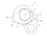
- the control shaft 6 has a pair of arm portions 27 that protrude outward in the radial direction of the control shaft at a predetermined position in the axial direction. Further, as shown in FIG. 5, a stopper member 37 as a control shaft side stopper is fixed at a predetermined position in the axial direction of the control shaft 6.
- One end of an elongated link member 28 is rotatably connected to the arm portions 27 and 27 via a connecting pin 29.
- the link member 28 is connected to an actuator (not shown) located outside the oil pan 31 and reciprocates along the direction perpendicular to the crankshaft axis.
- the control shaft 6 rotates when the reciprocating motion of the link member 28 is transmitted through the arm portions 27 and 27.
- the actuator may be, for example, an electric motor or a hydraulically driven actuator.
- the stopper member 37 regulates the rotation of the control shaft 6 by being abutted against the main body high compression ratio side stopper portion 35 or the main body low compression ratio side stopper portion 36 formed on the main bearing cap 22.
- the stopper member 37 has a substantially fan shape, is abutted against the main body high compression ratio side stopper portion 35, and controls the control shaft high compression ratio side stopper portion 38 that restricts the rotation of the control shaft 6 toward the high compression ratio side.
- a control shaft low compression ratio side stopper portion 39 which is abutted against the compression ratio side stopper portion 36 and restricts the rotation of the control shaft 6 toward the low compression ratio side.
- the control shaft high compression ratio side stopper portion 38 and the control shaft low compression ratio side stopper portion 39 are formed at positions separated from each other in the control shaft circumferential direction.
- a control shaft high compression ratio side stopper surface 40 is formed on the control shaft high compression ratio side stopper portion 38 as a control shaft side stopper surface that abuts against the main body high compression ratio side stopper portion 35.
- control shaft high compression ratio side stopper portion 38 is formed so that the thickness along the control shaft radial direction of the portion abutted against the main body high compression ratio side stopper portion 35 is relatively thick. The whole projects in a substantially triangular shape when viewed in the shaft axial direction.
- the control shaft low compression ratio side stopper portion 39 is formed with a control shaft low compression ratio side stopper surface 41 as a control shaft side stopper surface abutted against the main body low compression ratio side stopper portion 36.
- control shaft low compression ratio side stopper portion 39 is formed so that the thickness along the control shaft radial direction of the portion abutted against the main body low compression ratio side stopper portion 36 is relatively thick. The whole projects in a substantially triangular shape when viewed in the shaft axial direction.
- the main body high compression ratio side stopper portion 35 and the main body low compression ratio side stopper portion 36 are formed on both sides of the control shaft 6 so as to be separated from each other.
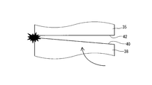
- the main body high compression ratio side stopper portion 35 has a main body high compression ratio side stopper surface 42 as a main body side stopper surface against which the control shaft high compression ratio side stopper surface 40 of the stopper member 37 is abutted.
- the main body high compression ratio side stopper portion 35 is formed so that the thickness of the portion against which the control shaft high compression ratio side stopper portion 38 abuts is relatively thick as viewed in the control shaft axial direction.
- the main body high compression ratio side stopper portion 35 is formed such that the wall thickness becomes relatively thicker as the distance from the control shaft rotation center C is longer as viewed in the control shaft axial direction.
- the main body low compression ratio side stopper portion 36 has a main body low compression ratio side stopper surface 43 as a main body side stopper surface against which the control shaft low compression ratio side stopper surface 41 of the stopper member 37 is abutted.
- variable compression ratio mechanism 1 when the control shaft 6 rotates, the center position of the eccentric shaft portion 7 changes and the swing support position of the other end of the control link 8 changes.
- the swing support position of the control link 8 changes, the stroke of the piston 2 in the cylinder 15 changes, and the position of the piston 2 at the piston top dead center (TDC) becomes higher or lower. This makes it possible to change the engine compression ratio.
- control shaft high compression ratio side stopper portion 38 of the stopper member 37 is brought into contact with the main body high compression ratio side stopper portion 35, whereby the reference position of the control shaft 6 on the high compression ratio side can be learned. Yes. Furthermore, it is possible to learn the reference position of the control shaft 6 on the low compression ratio side by abutting the control shaft low compression ratio side stopper portion 39 of the stopper member 37 against the main body low compression ratio side stopper portion 36. Yes.
- the control shaft high compression ratio side stopper surface 40 of the stopper member 37 is abutted against the main body high compression ratio side stopper surface 42 formed on the main body high compression ratio side stopper portion 35, or is formed on the main body low compression ratio side stopper portion 36.
- each stopper surface 40, 41, 42 is provided in the configuration in which the rotation of the control shaft 6 is regulated by abutting the control shaft low compression ratio side stopper surface 41 of the stopper member 37 against the main body low compression ratio side stopper surface 43.
- the positions of the main body side stopper surfaces 42 and 43 against which the control shaft side stopper surfaces 40 and 41 are abutted change due to variations in the shape and the like of 43 and 43.
- control shaft low compression ratio side stopper surface 41 is abutted against the main body low compression ratio side stopper surface 43, the load generated in both the main body low compression ratio side stopper portion 36 and the stopper member 37 is controlled by the control shaft 6. If the rotational torque is constant, the distance from the control shaft rotation center C increases as it is abutted at a close position.
- the control shaft high compression ratio side stopper surface 40 when the control shaft high compression ratio side stopper surface 40 is abutted against the main body high compression ratio side stopper surface 42, the distance from the control shaft rotation center C is as viewed in the control shaft axial direction.
- the control shaft high compression ratio side stopper surface 40 comes into contact with the main body high compression ratio side stopper surface 42 at a relatively close position (FIG. 6 a), the main body high compression ratio side stopper surface 42 and the control shaft high compression ratio.
- the side stopper surface 40 comes into surface contact without any contact (FIG. 6b)
- the control shaft high compression ratio side stopper surface 40 has a main body high compression ratio at a position relatively far from the control shaft rotation center C.
- the controller If the rotational torque constant Rushafuto 6, the load that occurs in both the body and high compression ratio side stopper portion 35 and the stopper member 37 when the abutted relatively large.
- the distance from the control shaft rotation center C to the contact position between them is determined by the control shaft axis.
- the control shaft high compression ratio side stopper surface 40 is relatively longer than the case where the control shaft high compression ratio side stopper surface 42 comes into contact with the main body high compression ratio side stopper surface 42 at a position relatively close to the control shaft rotation center C. Relative to the case where the control shaft high compression ratio side stopper surface 40 comes into contact with the main body high compression ratio side stopper surface 42 at a position relatively far from the control shaft rotation center C. Can be considered shorter.
- the control shaft high compression ratio side stopper surface 40 is opposed to the main body high compression ratio side stopper surface 42 in the axial direction of the control shaft. It is set so that the distance from the control shaft rotation center C is one-sided on the far side. Further, when the stopper member 37 is abutted against the main body low compression ratio side stopper portion 36, the control shaft low compression ratio side stopper surface 41 controls the main body low compression ratio side stopper surface 43 as viewed in the control shaft axial direction. It is set so that the distance from the shaft rotation center C is one-sided on the far side.
- control shaft high compression ratio side stopper portion 38 and the control shaft low compression ratio side stopper portion 39 are formed apart from each other in the circumferential direction of the control shaft, the control shaft having a minimum size at a necessary position is formed.
- the high compression ratio side stopper portion 38 and the control shaft low compression ratio side stopper portion 39 can be set. That is, the stopper member 37 can be reduced in size as compared with the configuration in which the control shaft high compression ratio side stopper portion 38 and the control shaft low compression ratio side stopper portion 39 are formed as one stopper portion. The weight can be reduced.
- the control shaft high compression ratio side stopper portion 38 is formed so that the thickness of the portion abutted against the main body high compression ratio side stopper portion 35 along the control shaft radial direction is relatively thick. Therefore, the control shaft high compression ratio side stopper portion 38 can ensure the required strength by setting the wall thickness along the control shaft radial direction to the minimum necessary thickness.
- the control shaft low compression ratio side stopper portion 39 is formed so that the thickness of the portion abutted against the main body low compression ratio side stopper portion 36 along the control shaft radial direction is relatively thick. Therefore, the control shaft low compression ratio side stopper portion 39 can ensure the required strength by setting the wall thickness along the control shaft radial direction to the minimum necessary thickness.
- the main body high compression ratio side stopper portion 35 is formed so that the thickness of the portion that comes into contact with the control shaft high compression ratio side stopper portion 38 when the control shaft high compression ratio side stopper portion 38 is abutted is relatively thick as viewed in the control shaft axial direction. Yes. Therefore, the main body high compression ratio side stopper portion 35 can improve the strength when the control shaft high compression ratio side stopper portion 38 is abutted.
- the main body low compression ratio side stopper portion 36 may also be formed so that the thickness of the portion against which the control shaft low compression ratio side stopper portion 39 abuts is relatively thick as viewed in the axial direction of the control shaft. . That is, the main body low compression ratio side stopper portion 36 may also be formed so that the wall thickness becomes relatively thicker as the distance from the control shaft rotation center C is longer in the axial direction of the control shaft.
- the distance between the stopper surfaces when abutting is set to be relatively longer toward the control shaft rotation center C side on both the high compression ratio side and the low compression ratio side.
- only one of them may be set such that the distance between the stopper surfaces when being abutted is relatively longer toward the control shaft rotation center C side.
- the distance between the stopper surfaces when abutting may be set to be relatively longer toward the control shaft rotation center C side.
- a separate stopper member 37 is fixed to the control shaft 6, but the control shaft side stopper may be machined with respect to the forged control shaft 6.
Abstract
Description
Claims (4)
- コントロールシャフトの回転位置に応じて内燃機関の圧縮比を連続的に変化させることが可能な可変圧縮比機構と、上記コントロールシャフトの回転を規制する本体側ストッパと、を有する内燃機関において、
上記コントロールシャフトは、上記本体側ストッパと突き当たるコントロールシャフト側ストッパを備え、
上記コントロールシャフト側ストッパは、上記本体側ストッパに突き当てられるコントロールシャフト側ストッパ面を有し、
上記本体側ストッパは、上記コントロールシャフト側ストッパに突き当てられる本体側ストッパ面を有し、
上記コントロールシャフト側ストッパが上記本体側ストッパに突き当てられる際に、上記本体側ストッパ面と上記コントロールシャフト側ストッパ面との間の距離は、コントロールシャフト軸方向視で、コントロールシャフト回転中心側が長くなるよう設定されている内燃機関。 - 上記コントロールシャフト側ストッパは、上記コントロールシャフトの高圧縮比側への変位を規制するコントロールシャフト高圧縮比側ストッパ部と、上記コントロールシャフトの低圧縮比側への変位を規制するコントロールシャフト低圧縮比側ストッパ部と、を有し、
上記コントロールシャフト高圧縮比側ストッパ部と上記コントロールシャフト低圧縮比側ストッパ部とは、上記コントロールシャフトの周方向に互いに離間して形成されている請求項1に記載の内燃機関。 - 上記コントロールシャフト側ストッパは、上記本体側ストッパに突き当てられる部分のコントロールシャフト径方向に沿った肉厚が相対的に厚くなるように形成されている請求項1または2に記載の内燃機関。
- 上記本体側ストッパは、上記コントロールシャフト回転中心からの距離が遠いほど肉厚が相対的に厚くなるように形成されている請求項1~3のいずれかに記載の内燃機関。
Priority Applications (10)
| Application Number | Priority Date | Filing Date | Title |
|---|---|---|---|
| CA2981686A CA2981686C (en) | 2015-04-03 | 2015-04-03 | Internal combustion engine |
| KR1020177030562A KR101854098B1 (ko) | 2015-04-03 | 2015-04-03 | 내연 기관 |
| RU2017135062A RU2658870C1 (ru) | 2015-04-03 | 2015-04-03 | Двигатель внутреннего сгорания |
| PCT/JP2015/060607 WO2016157521A1 (ja) | 2015-04-03 | 2015-04-03 | 内燃機関 |
| BR112017020640-4A BR112017020640B1 (pt) | 2015-04-03 | Motor de combustão interna | |
| MX2017012468A MX365699B (es) | 2015-04-03 | 2015-04-03 | Motor de combustión interna. |
| EP15887667.2A EP3279447B1 (en) | 2015-04-03 | 2015-04-03 | Internal combustion engine |
| CN201580078389.4A CN107429612B (zh) | 2015-04-03 | 2015-04-03 | 内燃机 |
| US15/570,247 US10190491B2 (en) | 2015-04-03 | 2015-04-03 | Internal combustion engine |
| JP2017509122A JP6380655B2 (ja) | 2015-04-03 | 2015-04-03 | 内燃機関 |
Applications Claiming Priority (1)
| Application Number | Priority Date | Filing Date | Title |
|---|---|---|---|
| PCT/JP2015/060607 WO2016157521A1 (ja) | 2015-04-03 | 2015-04-03 | 内燃機関 |
Publications (1)
| Publication Number | Publication Date |
|---|---|
| WO2016157521A1 true WO2016157521A1 (ja) | 2016-10-06 |
Family
ID=57006628
Family Applications (1)
| Application Number | Title | Priority Date | Filing Date |
|---|---|---|---|
| PCT/JP2015/060607 WO2016157521A1 (ja) | 2015-04-03 | 2015-04-03 | 内燃機関 |
Country Status (9)
| Country | Link |
|---|---|
| US (1) | US10190491B2 (ja) |
| EP (1) | EP3279447B1 (ja) |
| JP (1) | JP6380655B2 (ja) |
| KR (1) | KR101854098B1 (ja) |
| CN (1) | CN107429612B (ja) |
| CA (1) | CA2981686C (ja) |
| MX (1) | MX365699B (ja) |
| RU (1) | RU2658870C1 (ja) |
| WO (1) | WO2016157521A1 (ja) |
Citations (4)
| Publication number | Priority date | Publication date | Assignee | Title |
|---|---|---|---|---|
| JP2005083203A (ja) * | 2003-09-04 | 2005-03-31 | Mitsubishi Electric Corp | 制御軸の回動範囲規制機構 |
| JP2006226133A (ja) * | 2005-02-15 | 2006-08-31 | Nissan Motor Co Ltd | 内燃機関の可変圧縮比装置 |
| JP2009185629A (ja) * | 2008-02-04 | 2009-08-20 | Nissan Motor Co Ltd | 可変圧縮比エンジン |
| JP2011169152A (ja) * | 2010-02-16 | 2011-09-01 | Nissan Motor Co Ltd | 内燃機関の可変圧縮比装置 |
Family Cites Families (9)
| Publication number | Priority date | Publication date | Assignee | Title |
|---|---|---|---|---|
| JP3298335B2 (ja) * | 1994-10-31 | 2002-07-02 | 株式会社日立製作所 | 回転体の取付構造及びこれを用いた電動送風機 |
| RU2256085C2 (ru) * | 2000-08-08 | 2005-07-10 | Даймлеркрайслер Аг | Поршневой двигатель внутреннего сгорания с переменной степенью сжатия |
| JP4621627B2 (ja) * | 2006-04-24 | 2011-01-26 | 本田技研工業株式会社 | 内燃機関の仕事量算出装置 |
| RU2338079C1 (ru) * | 2007-05-21 | 2008-11-10 | Общество с ограниченной ответственностью Научно-производственное предприятие "Электронные системы специальной техники" | Способ работы двигателя внутреннего сгорания и двигатель внутреннего сгорания |
| CN101725626B (zh) * | 2008-10-24 | 2013-06-05 | 鸿富锦精密工业(深圳)有限公司 | 铰链结构 |
| JP5953929B2 (ja) * | 2012-05-18 | 2016-07-20 | 日産自動車株式会社 | 可変圧縮比内燃機関 |
| CN202834160U (zh) * | 2012-09-27 | 2013-03-27 | 浙江盾安机械有限公司 | 球阀 |
| JP5765500B2 (ja) * | 2013-02-20 | 2015-08-19 | 日産自動車株式会社 | 可変圧縮比内燃機関 |
| CN203963828U (zh) * | 2014-06-25 | 2014-11-26 | 宁波高新区赛尔富电子有限公司 | 一种灯具 |
-
2015
- 2015-04-03 EP EP15887667.2A patent/EP3279447B1/en active Active
- 2015-04-03 RU RU2017135062A patent/RU2658870C1/ru active
- 2015-04-03 MX MX2017012468A patent/MX365699B/es active IP Right Grant
- 2015-04-03 US US15/570,247 patent/US10190491B2/en active Active
- 2015-04-03 JP JP2017509122A patent/JP6380655B2/ja active Active
- 2015-04-03 CA CA2981686A patent/CA2981686C/en active Active
- 2015-04-03 KR KR1020177030562A patent/KR101854098B1/ko active IP Right Grant
- 2015-04-03 CN CN201580078389.4A patent/CN107429612B/zh active Active
- 2015-04-03 WO PCT/JP2015/060607 patent/WO2016157521A1/ja active Application Filing
Patent Citations (4)
| Publication number | Priority date | Publication date | Assignee | Title |
|---|---|---|---|---|
| JP2005083203A (ja) * | 2003-09-04 | 2005-03-31 | Mitsubishi Electric Corp | 制御軸の回動範囲規制機構 |
| JP2006226133A (ja) * | 2005-02-15 | 2006-08-31 | Nissan Motor Co Ltd | 内燃機関の可変圧縮比装置 |
| JP2009185629A (ja) * | 2008-02-04 | 2009-08-20 | Nissan Motor Co Ltd | 可変圧縮比エンジン |
| JP2011169152A (ja) * | 2010-02-16 | 2011-09-01 | Nissan Motor Co Ltd | 内燃機関の可変圧縮比装置 |
Non-Patent Citations (1)
| Title |
|---|
| See also references of EP3279447A4 * |
Also Published As
| Publication number | Publication date |
|---|---|
| MX365699B (es) | 2019-06-11 |
| BR112017020640A2 (pt) | 2018-06-26 |
| CN107429612A (zh) | 2017-12-01 |
| JP6380655B2 (ja) | 2018-08-29 |
| US20180142618A1 (en) | 2018-05-24 |
| EP3279447A1 (en) | 2018-02-07 |
| CN107429612B (zh) | 2018-10-30 |
| KR20170127568A (ko) | 2017-11-21 |
| CA2981686A1 (en) | 2016-10-06 |
| US10190491B2 (en) | 2019-01-29 |
| MX2017012468A (es) | 2018-01-23 |
| EP3279447A4 (en) | 2018-02-07 |
| CA2981686C (en) | 2018-05-01 |
| EP3279447B1 (en) | 2018-08-29 |
| KR101854098B1 (ko) | 2018-05-02 |
| RU2658870C1 (ru) | 2018-06-25 |
| JPWO2016157521A1 (ja) | 2017-10-19 |
Similar Documents
| Publication | Publication Date | Title |
|---|---|---|
| US8881695B2 (en) | Variable compression ratio internal combustion engine | |
| US7228838B2 (en) | Internal combustion engine | |
| JP5971422B2 (ja) | 内燃機関の複リンク式ピストンクランク機構 | |
| JP2009036128A (ja) | 複リンク式可変圧縮比エンジン | |
| JP6160779B2 (ja) | 軸受構造 | |
| JP5949148B2 (ja) | 複リンク式内燃機関 | |
| JP5810675B2 (ja) | 内燃機関の複リンク式ピストン−クランク機構 | |
| WO2015025684A1 (ja) | 内燃機関 | |
| JP6380655B2 (ja) | 内燃機関 | |
| JP4816588B2 (ja) | 内燃機関の複リンク式ピストン−クランク機構 | |
| US20140260961A1 (en) | Piston Pinbore Busing With Anti-Rotation Feature | |
| JP7041549B2 (ja) | 内燃機関の複リンク式ピストンクランク機構 | |
| JP4816587B2 (ja) | 内燃機関の複リンク式ピストン−クランク機構 | |
| JP5696573B2 (ja) | 内燃機関の複リンク式ピストン−クランク機構 | |
| JP6485174B2 (ja) | 内燃機関 | |
| JP2006226115A (ja) | 内燃機関の油圧駆動装置 | |
| JP4581675B2 (ja) | 内燃機関 | |
| JP6375769B2 (ja) | 内燃機関の複リンク式ピストンクランク機構の軸受構造。 | |
| JP7464345B2 (ja) | モノブロック式内燃機関 | |
| JP2010203345A (ja) | 複リンク式内燃機関の軸受構造 | |
| JP5668601B2 (ja) | 内燃機関の複リンク式ピストン−クランク機構 | |
| JP2023016651A (ja) | ロッカアーム揺動軸位置可変式圧縮比連続可変装置 | |
| JP2008069679A (ja) | ストローク特性可変エンジン | |
| JP2019070364A (ja) | V型多気筒内燃機関のシリンダブロック |
Legal Events
| Date | Code | Title | Description |
|---|---|---|---|
| 121 | Ep: the epo has been informed by wipo that ep was designated in this application |
Ref document number: 15887667 Country of ref document: EP Kind code of ref document: A1 |
|
| ENP | Entry into the national phase |
Ref document number: 2017509122 Country of ref document: JP Kind code of ref document: A |
|
| WWE | Wipo information: entry into national phase |
Ref document number: MX/A/2017/012468 Country of ref document: MX |
|
| ENP | Entry into the national phase |
Ref document number: 2981686 Country of ref document: CA |
|
| NENP | Non-entry into the national phase |
Ref country code: DE |
|
| WWE | Wipo information: entry into national phase |
Ref document number: 2017135062 Country of ref document: RU |
|
| ENP | Entry into the national phase |
Ref document number: 20177030562 Country of ref document: KR Kind code of ref document: A |
|
| WWE | Wipo information: entry into national phase |
Ref document number: 15570247 Country of ref document: US |
|
| REG | Reference to national code |
Ref country code: BR Ref legal event code: B01A Ref document number: 112017020640 Country of ref document: BR |
|
| ENP | Entry into the national phase |
Ref document number: 112017020640 Country of ref document: BR Kind code of ref document: A2 Effective date: 20170926 |