WO2016153040A1 - ヒートポンプ - Google Patents
ヒートポンプ Download PDFInfo
- Publication number
- WO2016153040A1 WO2016153040A1 PCT/JP2016/059628 JP2016059628W WO2016153040A1 WO 2016153040 A1 WO2016153040 A1 WO 2016153040A1 JP 2016059628 W JP2016059628 W JP 2016059628W WO 2016153040 A1 WO2016153040 A1 WO 2016153040A1
- Authority
- WO
- WIPO (PCT)
- Prior art keywords
- heat pump
- wick
- container
- heat
- porous body
- Prior art date
- Legal status (The legal status is an assumption and is not a legal conclusion. Google has not performed a legal analysis and makes no representation as to the accuracy of the status listed.)
- Ceased
Links
Images
Classifications
-
- F—MECHANICAL ENGINEERING; LIGHTING; HEATING; WEAPONS; BLASTING
- F28—HEAT EXCHANGE IN GENERAL
- F28D—HEAT-EXCHANGE APPARATUS, NOT PROVIDED FOR IN ANOTHER SUBCLASS, IN WHICH THE HEAT-EXCHANGE MEDIA DO NOT COME INTO DIRECT CONTACT
- F28D15/00—Heat-exchange apparatus with the intermediate heat-transfer medium in closed tubes passing into or through the conduit walls ; Heat-exchange apparatus employing intermediate heat-transfer medium or bodies
- F28D15/02—Heat-exchange apparatus with the intermediate heat-transfer medium in closed tubes passing into or through the conduit walls ; Heat-exchange apparatus employing intermediate heat-transfer medium or bodies in which the medium condenses and evaporates, e.g. heat pipes
- F28D15/0233—Heat-exchange apparatus with the intermediate heat-transfer medium in closed tubes passing into or through the conduit walls ; Heat-exchange apparatus employing intermediate heat-transfer medium or bodies in which the medium condenses and evaporates, e.g. heat pipes the conduits having a particular shape, e.g. non-circular cross-section, annular
-
- F—MECHANICAL ENGINEERING; LIGHTING; HEATING; WEAPONS; BLASTING
- F28—HEAT EXCHANGE IN GENERAL
- F28D—HEAT-EXCHANGE APPARATUS, NOT PROVIDED FOR IN ANOTHER SUBCLASS, IN WHICH THE HEAT-EXCHANGE MEDIA DO NOT COME INTO DIRECT CONTACT
- F28D15/00—Heat-exchange apparatus with the intermediate heat-transfer medium in closed tubes passing into or through the conduit walls ; Heat-exchange apparatus employing intermediate heat-transfer medium or bodies
- F28D15/02—Heat-exchange apparatus with the intermediate heat-transfer medium in closed tubes passing into or through the conduit walls ; Heat-exchange apparatus employing intermediate heat-transfer medium or bodies in which the medium condenses and evaporates, e.g. heat pipes
-
- F—MECHANICAL ENGINEERING; LIGHTING; HEATING; WEAPONS; BLASTING
- F28—HEAT EXCHANGE IN GENERAL
- F28D—HEAT-EXCHANGE APPARATUS, NOT PROVIDED FOR IN ANOTHER SUBCLASS, IN WHICH THE HEAT-EXCHANGE MEDIA DO NOT COME INTO DIRECT CONTACT
- F28D15/00—Heat-exchange apparatus with the intermediate heat-transfer medium in closed tubes passing into or through the conduit walls ; Heat-exchange apparatus employing intermediate heat-transfer medium or bodies
- F28D15/02—Heat-exchange apparatus with the intermediate heat-transfer medium in closed tubes passing into or through the conduit walls ; Heat-exchange apparatus employing intermediate heat-transfer medium or bodies in which the medium condenses and evaporates, e.g. heat pipes
- F28D15/04—Heat-exchange apparatus with the intermediate heat-transfer medium in closed tubes passing into or through the conduit walls ; Heat-exchange apparatus employing intermediate heat-transfer medium or bodies in which the medium condenses and evaporates, e.g. heat pipes with tubes having a capillary structure
- F28D15/046—Heat-exchange apparatus with the intermediate heat-transfer medium in closed tubes passing into or through the conduit walls ; Heat-exchange apparatus employing intermediate heat-transfer medium or bodies in which the medium condenses and evaporates, e.g. heat pipes with tubes having a capillary structure characterised by the material or the construction of the capillary structure
-
- F—MECHANICAL ENGINEERING; LIGHTING; HEATING; WEAPONS; BLASTING
- F28—HEAT EXCHANGE IN GENERAL
- F28F—DETAILS OF HEAT-EXCHANGE AND HEAT-TRANSFER APPARATUS, OF GENERAL APPLICATION
- F28F21/00—Constructions of heat-exchange apparatus characterised by the selection of particular materials
- F28F21/08—Constructions of heat-exchange apparatus characterised by the selection of particular materials of metal
- F28F21/081—Heat exchange elements made from metals or metal alloys
-
- H—ELECTRICITY
- H10—SEMICONDUCTOR DEVICES; ELECTRIC SOLID-STATE DEVICES NOT OTHERWISE PROVIDED FOR
- H10W—GENERIC PACKAGES, INTERCONNECTIONS, CONNECTORS OR OTHER CONSTRUCTIONAL DETAILS OF DEVICES COVERED BY CLASS H10
- H10W40/00—Arrangements for thermal protection or thermal control
- H10W40/70—Fillings or auxiliary members in containers or in encapsulations for thermal protection or control
- H10W40/73—Fillings or auxiliary members in containers or in encapsulations for thermal protection or control for cooling by change of state
-
- F—MECHANICAL ENGINEERING; LIGHTING; HEATING; WEAPONS; BLASTING
- F28—HEAT EXCHANGE IN GENERAL
- F28D—HEAT-EXCHANGE APPARATUS, NOT PROVIDED FOR IN ANOTHER SUBCLASS, IN WHICH THE HEAT-EXCHANGE MEDIA DO NOT COME INTO DIRECT CONTACT
- F28D15/00—Heat-exchange apparatus with the intermediate heat-transfer medium in closed tubes passing into or through the conduit walls ; Heat-exchange apparatus employing intermediate heat-transfer medium or bodies
- F28D15/02—Heat-exchange apparatus with the intermediate heat-transfer medium in closed tubes passing into or through the conduit walls ; Heat-exchange apparatus employing intermediate heat-transfer medium or bodies in which the medium condenses and evaporates, e.g. heat pipes
- F28D15/04—Heat-exchange apparatus with the intermediate heat-transfer medium in closed tubes passing into or through the conduit walls ; Heat-exchange apparatus employing intermediate heat-transfer medium or bodies in which the medium condenses and evaporates, e.g. heat pipes with tubes having a capillary structure
-
- F—MECHANICAL ENGINEERING; LIGHTING; HEATING; WEAPONS; BLASTING
- F28—HEAT EXCHANGE IN GENERAL
- F28D—HEAT-EXCHANGE APPARATUS, NOT PROVIDED FOR IN ANOTHER SUBCLASS, IN WHICH THE HEAT-EXCHANGE MEDIA DO NOT COME INTO DIRECT CONTACT
- F28D20/00—Heat storage plants or apparatus in general; Regenerative heat-exchange apparatus not covered by groups F28D17/00 or F28D19/00
- F28D2020/0004—Particular heat storage apparatus
- F28D2020/0013—Particular heat storage apparatus the heat storage material being enclosed in elements attached to or integral with heat exchange conduits
-
- F—MECHANICAL ENGINEERING; LIGHTING; HEATING; WEAPONS; BLASTING
- F28—HEAT EXCHANGE IN GENERAL
- F28D—HEAT-EXCHANGE APPARATUS, NOT PROVIDED FOR IN ANOTHER SUBCLASS, IN WHICH THE HEAT-EXCHANGE MEDIA DO NOT COME INTO DIRECT CONTACT
- F28D21/00—Heat-exchange apparatus not covered by any of the groups F28D1/00 - F28D20/00
- F28D2021/0019—Other heat exchangers for particular applications; Heat exchange systems not otherwise provided for
- F28D2021/0028—Other heat exchangers for particular applications; Heat exchange systems not otherwise provided for for cooling heat generating elements, e.g. for cooling electronic components or electric devices
-
- F—MECHANICAL ENGINEERING; LIGHTING; HEATING; WEAPONS; BLASTING
- F28—HEAT EXCHANGE IN GENERAL
- F28F—DETAILS OF HEAT-EXCHANGE AND HEAT-TRANSFER APPARATUS, OF GENERAL APPLICATION
- F28F2255/00—Heat exchanger elements made of materials having special features or resulting from particular manufacturing processes
- F28F2255/06—Heat exchanger elements made of materials having special features or resulting from particular manufacturing processes composite, e.g. polymers with fillers or fibres
Definitions
- the present invention relates to a heat pump.
- cooling elements which are high-speed, high-output, highly integrated parts.
- One typical cooling system is a heat pump (typically a heat pipe).
- a heat pipe has an apparent thermal conductivity of an exterior member (hereinafter referred to as “container”) constituting the heat pipe that is several times to several tens of times that of a metal such as copper or aluminum.
- the general heat pipe principle is as follows.
- the heat pipe has a structure in which a working liquid and a wick 4 for transporting the working liquid by capillary force are accommodated inside the container 2.
- the hydraulic fluid moves as indicated by the arrow. That is, the evaporation unit that absorbs heat from the heating element absorbs heat from the heating element, evaporates in the heat pipe, moves to the condensation unit, is cooled, and returns to the liquid phase.
- the working fluid that has returned to the liquid phase is moved again to the heating element side (evaporating section) by the capillary force of the wick structure, and cools the heating element.
- a working fluid typically water
- a metal typically Cu, Al, etc.
- the wick includes a fibrous metal, a sintered metal, a groove.
- Members such as a structure and a metal mesh are employed (Patent Document 1).
- Patent Documents 1 and 2 In order to deal with such a problem, Patent Document 1 employs a structure in which a thin container portion and a round container portion in which opposed wicks are close to each other are combined (FIG. 2 of Patent Document 1). In patent document 2, in order to improve capillary force, the wick with small flow resistance is arrange
- An object of the present invention is to provide a heat pump (preferably a heat pipe) having a large amount of working fluid that can be sealed and having a high heat transport capability.
- the present inventors can increase the amount of water that can be sealed by arranging a porous body having pores with a pore diameter of 100 nm or less on the surface of the wick. It has been found that the occurrence of dryout can be suppressed and the amount of heat transport can be increased.
- a heat pump comprising a container, a working fluid sealed in the container, and a wick, wherein the average pore diameter of the pores is 100 nm on the surface of the wick.
- a heat pump is provided in which the following porous body is disposed.
- a heat pump comprising a container, a working fluid sealed in the container, and a wick, wherein the specific surface area is 100 m 2 / g on the surface of the wick.
- a heat pump is provided in which the porous body as described above is arranged.
- a heat pump comprising a container, a working fluid enclosed in the container, and a wick, wherein the working fluid has a retention rate of 5 on the surface of the wick.
- a heat pump is provided in which a porous body having a volume% or more is disposed.
- a heat dissipation device comprising the heat pump of the present invention.
- an electronic apparatus comprising the heat pump of the present invention or the heat dissipation device of the present invention.
- the amount of hydraulic fluid that can be sealed in the container can be increased. Since the heat pump of the present invention containing a large amount of hydraulic fluid is less likely to dry out and has a high heat transport capability, the heat generating element can be cooled more efficiently than the heat pump of the present invention.
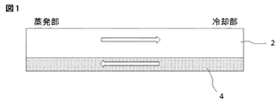
- FIG. 1 shows the general structure of a heat pipe.
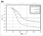
- FIG. 2 shows measurement results of thermogravimetry for each porous body in the example.
- the “heat pump” means a device having a container, a working fluid sealed in the container, and a wick, and capable of transporting heat from the evaporation section to the cooling section. .
- the working fluid absorbs heat in the evaporation section and evaporates, and the working fluid that has become a gas phase moves to the cooling section, releases heat in the cooling section, condenses, and becomes a liquid phase. This is performed by a cycle in which the working fluid moves to the evaporation section again by the capillary pressure of the wick.
- the shape, size, etc. of the heat pump are not particularly limited as long as the heat pump has the container, the working fluid, and the wick and can exhibit the heat transport ability.
- the heat pump may be pipe-shaped or plate-shaped, and includes so-called heat pipes, vapor chambers, and the like.
- the above container is a container having a space inside and is usually sealed.
- the shape and size of the container are not particularly limited, and may be any shape such as a hollow rectangular parallelepiped shape, a disk shape, or a rod shape.
- the container is preferably formed from a material with high thermal conductivity. Examples of such a material include copper and aluminum.
- the hydraulic fluid is not particularly limited as long as it can cause a gas-liquid phase change under the environment in the container.
- water an aqueous compound, alcohols, chlorofluorocarbon alternative, or the like can be used.
- the hydraulic fluid is an aqueous compound, preferably water.
- the wick is not particularly limited as long as it has a structure capable of moving the hydraulic fluid by capillary pressure.
- a structure capable of moving the hydraulic fluid by capillary pressure is referred to as a capillary structure, for example, a fine structure having irregularities such as pores, grooves, and protrusions, such as a fiber structure, a groove structure, and a mesh structure.
- the installation location of the wick is not particularly limited as long as it is continuously installed from the evaporation section to the condensation section inside the container.
- the wick may be installed on one inner wall surface, or may be installed on all inner wall surfaces.
- the wick may be formed integrally with the container, or may be formed by processing the inner wall surface of the container, or a separately manufactured wick may be attached to the inner wall surface of the container.
- the capillary structure of Wick is not particularly limited, and may be a known structure used in conventional heat pipes and vapor chambers.
- the wick may be an aggregate of grooves, irregularities or protrusions formed on the inner wall surface of the container at a predetermined interval, or may be a sintered metal, a sintered ceramic, or a fiber.
- the heat pipe of the present invention has a porous body disposed on the wick.
- the porous body may have an average pore size of 100 nm or less.
- the average pore diameter of the porous body is preferably 0.3 nm or more and 100 nm or less, more preferably 0.3 nm or more and 50 nm or less, and further preferably 0.3 nm or more and 20 nm or less.
- the porous body can hold more hydraulic fluid and the capillary pressure increases.
- the average pore diameter of the porous body can be measured by a gas adsorption method. Specifically, the average pore diameter can be calculated by physically adsorbing the gas on the pore surface, measuring the pore distribution from the relationship between the adsorption amount and the relative pressure.
- the gas nitrogen is used when the pore diameter is 0.7 nm or more, and argon is used when the pore diameter is less than 0.7 nm.
- the porous body may have a specific surface area of 100 m 2 / g or more.
- the specific surface area of the porous body is preferably 100 m 2 / g or more and 20,000 m 2 / g or less, more preferably 500 m 2 / g or more and 15,000 m 2 / g or less, and further preferably 1,000 m 2 / g or more. It can be 10,000 m 2 / g or less.
- the porous body can hold more hydraulic fluid by having a larger specific surface area.
- the specific surface area of the porous body can be measured by a gas adsorption method. Specifically, the specific surface area can be calculated from a calculation formula such as the BET method from the relationship between the adsorption amount and the relative pressure by physically adsorbing the gas on the pore surface.
- the gas nitrogen is used when the pore diameter is 0.7 nm or more, and argon is used when the pore diameter is less than 0.7 nm.
- the porous body may have a hydraulic fluid retention of 5% by volume or more, preferably 10% by volume or more, more preferably 20% by volume or more.
- a hydraulic fluid retention rate By having a larger hydraulic fluid retention rate, the porous body can hold more hydraulic fluid. By increasing this retention rate, the heat pump of the present invention can achieve a higher amount of heat transport.
- the hydraulic fluid retention rate means the ratio (volume%) of the hydraulic fluid that is adsorbed to the porous body with respect to the volume of the porous body.
- the retention rate of the hydraulic fluid is calculated from the weight change rate and the density of the porous body by measuring the weight change rate (decrease rate) when the porous body is heated from 40 ° C. to 160 ° C. by thermogravimetry. Can do.
- the porous body is not particularly limited, but may be, for example, zeolite or a porous metal complex.
- Other examples include carbon-based materials such as mesoporous silica and activated carbon, and diatomaceous earth.
- the zeolite is not particularly limited as long as it has the above-described pore diameter, specific surface area, or hydraulic fluid retention, and can be appropriately selected according to desired performance.
- Zeolite that can be used in a typical present invention includes, for example, IZA standard FAU type, LTA type, AFI type, MFI type, MOR type, AEL type, CHA type, BEA type, LTL type and the like.
- the porous metal complex means a porous material composed of metal ions and organic ligands. Porous metal complexes are well known to those skilled in the art and are also referred to as porous coordination polymers (PCP) or metal organic structures (MOF).
- PCP porous coordination polymers
- MOF metal organic structures
- the porous metal complex used in the present invention is not particularly limited as long as it has the above-described pore diameter, specific surface area or hydraulic fluid retention, and can be appropriately selected according to desired performance.
- Typical porous metal complexes that can be used in the present invention include MIL, ZIF, MOF, HKUST-1, and JAST-1.
- the porous body is preferably hydrophilic.
- a hydrophilic porous body when a hydrophilic working fluid such as water is used, the capillary pressure increases and the amount of heat transport can be increased.
- the desorption temperature of the hydraulic fluid varies depending on the type of porous body. Therefore, the operating temperature of the heat pump of the present invention can be controlled by adjusting the type and amount of the porous body disposed on the wick.
- porous body absorbs and releases energy when water is adsorbed and desorbed, heat can be transported more efficiently by using this adsorption and desorption energy.
- the heat pump of the present invention operates with only the latent heat of the hydraulic fluid to transport heat at a low temperature, and uses the adsorption / desorption energy of the porous body in addition to the latent heat of the hydraulic fluid at a high temperature. Heat can be transported.
- the method of disposing the porous body on the wick is not particularly limited, and examples thereof include a method of forming a porous film by coating or binding a fine powder of the porous body on the wick.
- the zeolite can be disposed on the wick by immersing the wick in a slurry containing zeolite and a low-melting glass, pulling up and heating.
- the wick is immersed in a solution containing the metal ions and organic ligands that are the raw materials of the porous metal complex, heated and dried, so that the porous material is porous on the wick.
- Metal complexes can be formed.
- the heat pump of the present invention has a high heat transport capability as described above, it is preferably used for a heat dissipation device.
- the present invention also provides a heat dissipation device comprising the heat pump of the present invention.
- the heat pump of the present invention can enclose a large amount of hydraulic fluid, it is advantageous for downsizing and is suitable for use in equipment that requires downsizing, such as electronic equipment.
- the present invention also provides an electronic apparatus comprising the heat pump of the present invention or the heat dissipation device of the present invention.
- Porous material 1 HPA (manufactured by Tosoh; Y-type zeolite, density 1.4 g / cm 3 )
- Porous material 2 AQSOA-Z01 (manufactured by Mitsubishi Plastics, zeolite, density 1.4 g / cm 3 )
- Porous body 3 BASOLITE C300 (manufactured by BASF; porous metal complex, density 0.35 g / cm 3 )
- the weight change rate from about 40 ° C. to about 160 ° C. in thermogravimetry is shown in Table 1 below. Moreover, the ratio (volume%) of the water reduction amount with respect to the volume of a porous body was computed from this weight change rate and density. The results are also shown in Table 1.
- these porous bodies can hold 28% by volume, 21% by volume and 10.5% by volume of water per volume, respectively. Therefore, it is considered that by arranging these porous bodies on the wick surface, the amount of moisture adsorption increases according to the amount of the porous bodies to be arranged, the occurrence of dryout is suppressed, and the heat transport amount increases.
- the heat pump of the present invention has a large amount of retained hydraulic fluid, hardly causes dryout, and has a high heat transport capability, it can be used in a wide range of applications. In particular, it can be used as a cooling device for electronic devices or the like in applications where small and efficient heat transport is required.
Landscapes
- Engineering & Computer Science (AREA)
- Physics & Mathematics (AREA)
- Thermal Sciences (AREA)
- Mechanical Engineering (AREA)
- General Engineering & Computer Science (AREA)
- Life Sciences & Earth Sciences (AREA)
- Sustainable Development (AREA)
- Cooling Or The Like Of Semiconductors Or Solid State Devices (AREA)
- Cooling Or The Like Of Electrical Apparatus (AREA)
- Sorption Type Refrigeration Machines (AREA)
Abstract
本発明は、コンテナと、該コンテナ内に封入される作動液と、ウィックとを有して成るヒートポンプであって、上記ウィックの表面に、細孔の平均孔径が100nm以下である多孔体が配置されていることを特徴とするヒートポンプを提供する。
Description
本発明は、ヒートポンプに関する。
近年、パソコンやスマートフォンなどの電子機器の小型化、高性能化が著しく、それに搭載されるマイクロプロセッサ(MPU)等の発熱部品を冷却するための冷却機構の小型化、省スペース化が強く望まれている。上記のMPUは、集積度が極めて高く、高速で演算、制御等の処理を行うので、多量の熱を放出する。このため、高速、高出力、高集積の部品である各種の電子素子(以下、「発熱素子」と称する)を冷却するために、各種の冷却システムが提案されてきた。その代表的な冷却システムの1つとして、ヒートポンプ(代表的にはヒートパイプ)がある。
ヒートパイプはそれを構成する外装部材(以下、「コンテナ」と称する)の見かけ上の熱伝導率が、銅やアルミニウム等の金属に対して数倍から数十倍程度に優れている。一般的なヒートパイプの原理は以下の通りである。
図1に示されるように、ヒートパイプは、コンテナ2の内部に、作動液と、毛細管力によって作動液を輸送するウィック4が収納された構造を有する。前記作動液は、矢印に示されるように移動する。即ち、発熱素子からの熱を吸収する蒸発部において発熱素子からの熱を吸収し、ヒートパイプ内で蒸発し、凝縮部に移動し、冷却されて液相に戻る。液相に戻った作動液は、ウィック構造体の毛細管力によって再び発熱素子側(蒸発部)に移動し、発熱素子を冷却する。
従来のヒートパイプは、金属(代表的にはCuやAl等)製コンテナの中に作動液(代表的には水)が入れられており、ウィックには、繊維状金属、焼結金属、溝構造、金属メッシュなどの部材が採用されている(特許文献1)。
近年の電子機器の小型化により、上記のヒートパイプもより小さく、薄いことが求められている。しかしながら、パイプ自体の厚みを薄くした場合、ウィックのコンテナに対する体積割合が増加するため、封入できる水の量が少なくなる。そのため、熱輸送能力が制限されること、また、毛細管限界によるドライアウトが生じることが課題となっている(特許文献1および2)。このような課題に対し、特許文献1では、対向させたウィックを近接化した薄型コンテナ部と丸型コンテナ部を組み合わせた構造を採用している(特許文献1の図2)。特許文献2では、毛細管力を向上させるために、流動抵抗の小さなウィックを凝縮部に配置している(特許文献2の図3)。
しかしながら、特許文献1および2に記載のヒートパイプでは、近年高まっている冷却性能を満たすには、封入できる作動液の量および熱輸送量共に十分であるとは言えない。また、特に高温動作の際、毛細管限界によるドライアウトが生じる可能性もある。
本発明は、封入できる作動液の量が多く、また、熱輸送能が高いヒートポンプ(好ましくはヒートパイプ)を提供することを目的とする。
本発明者らは、上記問題を解決すべく鋭意検討した結果、ウィックの表面に孔径100nm以下の孔を持つ多孔体を配置することにより、封入できる水の量を多くすることができ、これによりドライアウトの発生を抑制し、熱輸送量を大きくすることができることを見出した。
本発明の第1の要旨によれば、コンテナと、該コンテナ内に封入される作動液と、ウィックとを有して成るヒートポンプであって、上記ウィックの表面に、細孔の平均孔径が100nm以下である多孔体が配置されていることを特徴とするヒートポンプが提供される。
本発明の第2の要旨によれば、コンテナと、該コンテナ内に封入される作動液と、ウィックとを有して成るヒートポンプであって、上記ウィックの表面に、比表面積が100m2/g以上である多孔体が配置されていることを特徴とするヒートポンプが提供される。
本発明の第3の要旨によれば、コンテナと、該コンテナ内に封入される作動液と、ウィックとを有して成るヒートポンプであって、上記ウィックの表面に、作動液の保持率が5体積%以上である多孔体が配置されていることを特徴とするヒートポンプが提供される。
本発明の第4の要旨によれば、上記本発明のヒートポンプを有して成る放熱デバイスが提供される。
本発明の第5の要旨によれば、上記本発明のヒートポンプまたは上記本発明の放熱デバイスを有して成る電子機器が提供される。
本発明によれば、ウィックの表面に細孔の平均孔径が100nm以下である多孔体を配置することにより、コンテナ内に封入することができる作動液の量を多くすることができる。作動液を多く含む本発明のヒートポンプは、ドライアウトが生じにくく、熱輸送能が高いので、本発明のヒートポンプより、より効率的に発熱素子を冷却することが可能になる。
以下、本発明のヒートポンプについて説明する。
本明細書において、「ヒートポンプ」とは、コンテナと、該コンテナ内に封入される作動液と、ウィックとを有してなり、蒸発部から冷却部に熱を輸送することができるデバイスを意味する。熱の輸送は、作動液が蒸発部において熱を吸収して蒸発し、気相となった作動液が冷却部へと移動し、冷却部において熱を放出して凝縮し、液相となった作動液がウィックの毛管圧力により再び蒸発部へと移動するサイクルにより行われる。ヒートポンプは、上記のコンテナ、作動液およびウィックを有し、上記の熱輸送能を発揮できるものであれば、その形状、大きさ等は特に限定されない。例えば、ヒートポンプは、パイプ状であってもよく、板状であってもよく、所謂ヒートパイプ、ベーパーチャンバー等を包含する。
上記コンテナは、内部に空間を有する容器であり、通常密閉されている。コンテナの形状、大きさは特に限定されず、例えば中空の直方体状、円板状、棒状等いずれの形状であってもよい。コンテナは、熱伝導率の高い材料から形成されることが好ましい。このような材料としては、例えば銅、アルミニウム等が挙げられる。
上記作動液は、コンテナ内の環境下において気-液の相変化を生じ得るものであれば特に限定されず、例えば水、水性化合物、アルコール類、代替フロン等を用いることができる。一の態様において、作動液は水性化合物であり、好ましくは水である。
上記ウィックは、毛管圧力により作動液を移動させることができる構造を有するものであれば特に限定されない。本明細書において、毛管圧力により作動液を移動させることができる構造を、毛細管構造といい、例えば、細孔、溝、突起などの凹凸を有する微細構造、例えば、繊維構造、溝構造、網目構造等が挙げられる。
ウィックの設置箇所は、コンテナの内部に、蒸発部から凝縮部まで連続して設置される限り特に限定されない。例えば、ウィックは、コンテナが中空の直方体である場合、1つの内壁面上に設置されていてもよく、すべての内壁面に設置されていてもよい。ウィックは、コンテナと一体に成形してもよく、またはコンテナの内壁面を加工して形成してもよく、あるいは別途作製したウィックをコンテナの内壁面に貼り付けてもよい。
ウィックの毛細管構造は、特に限定されず、従来のヒートパイプおよびベーパーチャンバーにおいて用いられている公知の構造であってもよい。
ウィックは、コンテナの内壁面に所定の間隔で形成された溝、凹凸もしくは突起の集合体であってもよく、または焼結金属もしくは焼結セラミック、または繊維等であってもよい。
本発明のヒートパイプは、ウィック上に配置された多孔体を有する。
一の態様において、多孔体は、100nm以下の平均孔径を有し得る。多孔体の平均孔径は、好ましくは0.3nm以上100nm以下であり、より好ましくは0.3nm以上50nm以下、さらに好ましくは0.3nm以上20nm以下であり得る。より小さな平均孔径を有することにより、多孔体は、より多くの作動液を保持することができ、また、毛管圧力が大きくなる。
多孔体の平均孔径は、ガス吸着法により測定することができる。具体的には、ガスを細孔表面に物理的に吸着させ、その吸着量と相対圧との関係から細孔分布を測定し、平均孔径を算出することができる。上記ガスとしては、細孔径が0.7nm以上である場合には、窒素が用いられ、細孔径が0.7nm未満である場合には、アルゴンが用いられる。
一の態様において、多孔体は、100m2/g以上の比表面積を有し得る。多孔体の比表面積は、好ましくは100m2/g以上20,000m2/g以下であり、より好ましくは500m2/g以上15,000m2/g以下、さらに好ましくは1,000m2/g以上10,000m2/g以下であり得る。多孔体は、より大きな比表面積を有することにより、より多くの作動液を保持することができる。
多孔体の比表面積は、ガス吸着法により測定することができる。具体的には、ガスを細孔表面に物理的に吸着させ、その吸着量と相対圧との関係からBET法などの計算式から比表面積を算出することができる。上記ガスとしては、細孔径が0.7nm以上である場合には、窒素が用いられ、細孔径が0.7nm未満である場合には、アルゴンが用いられる。
一の態様において、多孔体は、5体積%以上、好ましくは10体積%以上、より好ましくは20体積%以上の作動液保持率を有し得る。より大きな作動液保持率を有することにより、多孔体はより多くの作動液を保持することができる。この保持率を高めることより、本発明のヒートポンプは、より高い熱輸送量を達成することができる。
尚、作動液保持率とは、多孔体の体積に対する、多孔体に吸着される作動液の割合(体積%)を意味する。該作動液の保持率は、熱重量測定により、多孔体を40℃から160℃まで加熱した場合の重量変化率(減少率)を測定し、重量変化率と多孔体の密度とから算出することができる。
多孔体は、特に限定されないが、例えば、ゼオライトまたは多孔性金属錯体であり得る。他にもメソポーラスシリカ、活性炭などのカーボン系材料、珪藻土などが挙げられる。
上記ゼオライトとしては、上記した細孔径、比表面積または作動液保持率を有するものであれば特に限定されず、所望の性能に応じて適宜選択することができる。代表的な本発明に用いることができるゼオライトは、例えば、IZA規格のFAUタイプ、LTAタイプ、AFIタイプ、MFIタイプ、MORタイプ、AELタイプ、CHAタイプ、BEAタイプ、LTLタイプ等が挙げられる。
多孔性金属錯体とは、金属イオンと有機配位子等から構成された多孔性物質を意味する。多孔性金属錯体は、当業者にはよく知られており、多孔性配位高分子(PCP:Porous Coordination Polymers)または金属有機構造体(MOF:Metal Organic Frameworks)とも称される。
本発明に用いられる多孔性金属錯体は、上記した細孔径、比表面積または作動液保持率を有するものであれば特に限定されず、所望の性能に応じて適宜選択することができる。代表的な本発明に用いることができる多孔性金属錯体は、例えば、MIL系、ZIF系、MOF系、HKUST-1、JAST-1などが挙げられる。
多孔体は、好ましくは親水性である。親水性の多孔体を用いることにより、親水性の作動液、例えば水を用いた場合に、毛管圧力が増大し、熱輸送量を高めることができる。
多孔体は、その種類に応じて、作動液の脱着温度が異なる。従って、ウィック上に配置する多孔体の種類および量を調節することにより、本発明のヒートポンプの作動温度を制御することができる。
また、多孔体は、水を吸脱着する際にエネルギーを吸収・放出するので、この吸脱着エネルギーを利用することにより、より効率的に熱を輸送することができる。
一の態様において、本発明のヒートポンプは、低温では作動液の潜熱のみで動作して熱を輸送し、高温では作動液の潜熱に加え、多孔体の吸脱着エネルギーを利用することにより、より効率的に熱を輸送することができる。
ウィック上に多孔体を配置する方法は、特に限定されず、例えば、コーティングにより多孔体膜を形成したり、多孔体の微粉末をウィック上に結着させたりする方法が挙げられる。例えば、ゼオライトを用いる場合には、ゼオライトと低融点ガラスを含んだスラリー中にウィックを浸漬し、引き上げて加熱することにより、ウィック上にゼオライトを配置することができる。また、多孔性金属錯体を用いる場合には、多孔性金属錯体の原料である金属イオンおよび有機配位子を含む溶液中にウィックを浸漬し、加熱して乾燥することにより、ウィック上に多孔性金属錯体を形成することができる。
本発明のヒートポンプは、上記のように熱輸送能が高いので、放熱デバイスに好適に用いられる。
従って、本発明は、本発明のヒートポンプを有して成る放熱デバイスをも提供する。
本発明のヒートポンプは、多量の作動液を封入することができるので、小型化に有利であり、小型化が要求される機器、例えば電子機器における利用に適している。
従って、本発明は、本発明のヒートポンプまたは本発明の放熱デバイスを有して成る電子機器をも提供する。
以上、本発明について説明したが、本発明はこれに限定されるものではなく、種々の改変が可能である。
多孔体の作動液の保持能を評価するために、下記多孔体1~3について、湿度約90%下で1日放置し、その後、熱重量測定(TG:Thermogravimetry)を行った。結果を、図2に示す。
多孔体1:HPA(東ソー製;Y型ゼオライト、密度1.4g/cm3)
多孔体2:AQSOA-Z01(三菱樹脂製、ゼオライト、密度1.4g/cm3)
多孔体3:BASOLITE C300(BASF社製;多孔性金属錯体、密度0.35g/cm3)
多孔体1:HPA(東ソー製;Y型ゼオライト、密度1.4g/cm3)
多孔体2:AQSOA-Z01(三菱樹脂製、ゼオライト、密度1.4g/cm3)
多孔体3:BASOLITE C300(BASF社製;多孔性金属錯体、密度0.35g/cm3)
熱重量測定における約40℃から約160℃までの重量変化率を下記表1に示す。また、この重量変化率と密度から、多孔体の体積に対する水減少量の割合(体積%)を算出した。結果を表1に併せて示す。
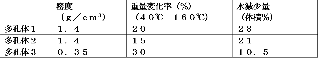
上記の結果から、これらの多孔体は、それぞれ、体積あたり28体積%、21体積%および10.5体積%の水を保持できることが確認された。従って、これらの多孔体をウィック表面に配置することにより、配置する多孔体の量に応じて、水分吸着量が増大し、ドライアウトの発生が抑制され、熱輸送量が増加すると考えられる。
本発明のヒートポンプは、作動液の保持量が多く、ドライアウトが生じにくく、熱輸送能が高いので、幅広い用途に用いることができる。特に、電子機器等の冷却デバイス等として、小型で効率的な熱輸送が求められる用途に用いることができる。
2…コンテナ
4…ウィック
4…ウィック
Claims (7)
- コンテナと、該コンテナ内に封入される作動液と、ウィックとを有して成るヒートポンプであって、
上記ウィックの表面に、細孔の平均孔径が100nm以下である多孔体が配置されていることを特徴とする、ヒートポンプ。 - 細孔の平均孔径が0.3nm以上20nm以下であることを特徴とする、請求項1に記載のヒートポンプ。
- コンテナと、該コンテナ内に封入される作動液と、ウィックとを有して成るヒートポンプであって、
上記ウィックの表面に、比表面積が100m2/g以上である多孔体が配置されていることを特徴とする、ヒートポンプ。 - コンテナと、該コンテナ内に封入される作動液と、ウィックとを有して成るヒートポンプであって、
上記ウィックの表面に、作動液の保持率が5体積%以上である多孔体が配置されていることを特徴とする、ヒートポンプ。 - 多孔体が、ゼオライトまたは多孔性金属錯体であることを特徴とする、請求項1~4のいずれか1項に記載のヒートポンプ。
- 請求項1~5のいずれか1項に記載のヒートポンプを有して成る放熱デバイス。
- 請求項1~5のいずれか1項に記載のヒートポンプまたは請求項6に記載の放熱デバイスを有して成る電子機器。
Priority Applications (2)
| Application Number | Priority Date | Filing Date | Title |
|---|---|---|---|
| CN201690000533.2U CN207662247U (zh) | 2015-03-26 | 2016-03-25 | 热泵 |
| JP2017508466A JP6481753B2 (ja) | 2015-03-26 | 2016-03-25 | ヒートポンプ |
Applications Claiming Priority (2)
| Application Number | Priority Date | Filing Date | Title |
|---|---|---|---|
| JP2015-064666 | 2015-03-26 | ||
| JP2015064666 | 2015-03-26 |
Publications (1)
| Publication Number | Publication Date |
|---|---|
| WO2016153040A1 true WO2016153040A1 (ja) | 2016-09-29 |
Family
ID=56977699
Family Applications (2)
| Application Number | Title | Priority Date | Filing Date |
|---|---|---|---|
| PCT/JP2015/080027 Ceased WO2016151916A1 (ja) | 2015-03-26 | 2015-10-23 | シート型ヒートパイプ |
| PCT/JP2016/059628 Ceased WO2016153040A1 (ja) | 2015-03-26 | 2016-03-25 | ヒートポンプ |
Family Applications Before (1)
| Application Number | Title | Priority Date | Filing Date |
|---|---|---|---|
| PCT/JP2015/080027 Ceased WO2016151916A1 (ja) | 2015-03-26 | 2015-10-23 | シート型ヒートパイプ |
Country Status (5)
| Country | Link |
|---|---|
| US (2) | US10544994B2 (ja) |
| JP (2) | JP6551514B2 (ja) |
| KR (1) | KR101992135B1 (ja) |
| CN (3) | CN111023879A (ja) |
| WO (2) | WO2016151916A1 (ja) |
Families Citing this family (56)
| Publication number | Priority date | Publication date | Assignee | Title |
|---|---|---|---|---|
| US12523431B2 (en) | 2014-09-15 | 2026-01-13 | Kelvin Thermal Technologies, Inc. | Polymer-based microfabricated thermal ground plane |
| US12385697B2 (en) | 2014-09-17 | 2025-08-12 | Kelvin Thermal Technologies, Inc. | Micropillar-enabled thermal ground plane |
| US11988453B2 (en) | 2014-09-17 | 2024-05-21 | Kelvin Thermal Technologies, Inc. | Thermal management planes |
| CN111023879A (zh) * | 2015-03-26 | 2020-04-17 | 株式会社村田制作所 | 薄型散热板 |
| US11543188B2 (en) | 2016-06-15 | 2023-01-03 | Delta Electronics, Inc. | Temperature plate device |
| US11306974B2 (en) * | 2016-06-15 | 2022-04-19 | Delta Electronics, Inc. | Temperature plate and heat dissipation device |
| TWI641796B (zh) * | 2016-11-18 | 2018-11-21 | 雙鴻科技股份有限公司 | 具阻熱機制的散熱元件 |
| CN108323137A (zh) * | 2017-01-18 | 2018-07-24 | 台达电子工业股份有限公司 | 均热板 |
| WO2018147283A1 (ja) * | 2017-02-07 | 2018-08-16 | 古河電気工業株式会社 | ベーパーチャンバ |
| WO2018208801A1 (en) | 2017-05-08 | 2018-11-15 | Kelvin Thermal Technologies, Inc. | Thermal management planes |
| EP3627086B1 (en) | 2017-05-16 | 2025-09-24 | LG Chem, Ltd. | Method for manufacturing heat pipe |
| JP6660925B2 (ja) * | 2017-07-12 | 2020-03-11 | エイジア ヴァイタル コンポーネンツ カンパニー リミテッド | 放熱装置の製造方法 |
| JP2019032134A (ja) * | 2017-08-09 | 2019-02-28 | レノボ・シンガポール・プライベート・リミテッド | プレート型熱輸送装置及び電子機器 |
| CN109413930A (zh) * | 2017-08-18 | 2019-03-01 | 鹏鼎控股(深圳)股份有限公司 | 均温板及应用该均温板的电子装置 |
| WO2019049781A1 (ja) | 2017-09-07 | 2019-03-14 | 株式会社村田製作所 | 回路ブロック集合体 |
| KR102316016B1 (ko) * | 2017-09-22 | 2021-10-22 | 주식회사 엘지화학 | 필름 및 히트 파이프의 제조 방법 |
| JP2021036175A (ja) | 2017-09-29 | 2021-03-04 | 株式会社村田製作所 | ベーパーチャンバー |
| WO2019065864A1 (ja) * | 2017-09-29 | 2019-04-04 | 株式会社村田製作所 | ベーパーチャンバー |
| JP2021039958A (ja) * | 2017-10-26 | 2021-03-11 | 株式会社村田製作所 | 電子機器の内部構造 |
| US20190204020A1 (en) * | 2018-01-03 | 2019-07-04 | Asia Vital Components (China) Co., Ltd. | Manufacturing method of heat dissipation device |
| US20190204019A1 (en) * | 2018-01-03 | 2019-07-04 | Asia Vital Components (China) Co., Ltd. | Heat dissipation device |
| US11304334B2 (en) * | 2018-06-14 | 2022-04-12 | Microsoft Technology Licensing, Llc | Vapor chamber having an electromagnetic shielding layer and methods of manufacturing the same |
| WO2020026908A1 (ja) | 2018-07-31 | 2020-02-06 | 株式会社村田製作所 | ベーパーチャンバー |
| CN217236573U (zh) | 2018-11-16 | 2022-08-19 | 株式会社村田制作所 | 均热板 |
| CN113166445A (zh) * | 2018-11-26 | 2021-07-23 | 富士胶片株式会社 | 储热片、储热构件及电子器件 |
| DE212019000445U1 (de) * | 2018-12-11 | 2021-08-17 | Kelvin Thermal Technologies | Dampfkammer |
| TWI711921B (zh) * | 2019-01-02 | 2020-12-01 | 奇鋐科技股份有限公司 | 散熱裝置 |
| US11092383B2 (en) | 2019-01-18 | 2021-08-17 | Asia Vital Components Co., Ltd. | Heat dissipation device |
| US12066256B2 (en) * | 2019-04-11 | 2024-08-20 | Cooler Master Co., Ltd. | Ultra-thin heat pipe and manufacturing method of the same |
| US10985085B2 (en) * | 2019-05-15 | 2021-04-20 | Advanced Semiconductor Engineering, Inc. | Semiconductor device package and method for manufacturing the same |
| CN110149784B (zh) * | 2019-06-03 | 2021-03-12 | Oppo广东移动通信有限公司 | 散热组件及电子设备 |
| CN114175424A (zh) * | 2019-07-30 | 2022-03-11 | 索尼半导体解决方案公司 | 半导体激光驱动装置、电子设备和制造半导体激光驱动装置的方法 |
| JP7350434B2 (ja) * | 2019-08-09 | 2023-09-26 | 矢崎エナジーシステム株式会社 | 構造体及びその製造方法 |
| JP6877513B2 (ja) * | 2019-11-06 | 2021-05-26 | 古河電気工業株式会社 | ベーパーチャンバ |
| CN215864819U (zh) | 2019-11-06 | 2022-02-18 | 古河电气工业株式会社 | 均热板 |
| KR102447783B1 (ko) | 2019-11-11 | 2022-09-27 | 주식회사 아모그린텍 | 시트형 히트 파이프 및 그 제조방법 |
| KR102488227B1 (ko) | 2019-11-11 | 2023-01-13 | 주식회사 아모그린텍 | 시트형 히트 파이프 및 그 제조방법 |
| KR102447793B1 (ko) | 2019-11-11 | 2022-09-27 | 주식회사 아모그린텍 | 시트형 히트 파이프 및 그 제조방법 |
| KR102513140B1 (ko) | 2019-11-11 | 2023-03-23 | 주식회사 아모그린텍 | 시트형 히트 파이프 및 그 제조방법 |
| KR102447779B1 (ko) | 2019-11-11 | 2022-09-27 | 주식회사 아모그린텍 | 시트형 히트 파이프 및 그 제조방법 |
| KR102159656B1 (ko) | 2020-01-10 | 2020-09-25 | 주식회사 진스텍 | 박판형 증기 챔버 및 그 제조방법 |
| US11643751B2 (en) * | 2020-03-10 | 2023-05-09 | Matrix Sensors, Inc. | Apparatus and method for producing a crystalline film on a substrate surface |
| US12059703B2 (en) * | 2020-03-10 | 2024-08-13 | Matrix Sensors, Inc. | Method for producing a crystalline film |
| CN111486732B (zh) * | 2020-03-19 | 2022-05-10 | 广州视源电子科技股份有限公司 | 一种用于散热装置的毛细结构加工方法 |
| JP7355707B2 (ja) * | 2020-05-13 | 2023-10-03 | 日立Astemo株式会社 | 半導体装置、バスバー及び電力変換装置 |
| US12464679B2 (en) | 2020-06-19 | 2025-11-04 | Kelvin Thermal Technologies, Inc. | Folding thermal ground plane |
| JP6934093B1 (ja) | 2020-07-13 | 2021-09-08 | レノボ・シンガポール・プライベート・リミテッド | 電子機器及び冷却モジュール |
| US11877423B2 (en) | 2020-10-08 | 2024-01-16 | Toyota Motor Engineering And Manufacturing North America, Inc. | Battery thermal management with large area planar heat pipes |
| EP4203636A4 (en) * | 2020-11-23 | 2024-02-28 | Samsung Electronics Co., Ltd. | HEAT DIFFUSION STRUCTURE AND ELECTRONIC DEVICE COMPRISING IT |
| KR102804063B1 (ko) * | 2020-12-28 | 2025-05-09 | 엘지디스플레이 주식회사 | 유기 발광 표시 장치 |
| US12111114B2 (en) * | 2021-01-29 | 2024-10-08 | Advanced Semiconductor Engineering, Inc. | Heat transfer element, method for forming the same and semiconductor structure comprising the same |
| TWI878479B (zh) * | 2021-03-04 | 2025-04-01 | 宸寰科技有限公司 | 薄型化封裝接著結構 |
| AT524582B1 (de) * | 2021-11-04 | 2022-07-15 | Miba Emobility Gmbh | Vorrichtung umfassend ein Elektronikbauteil |
| US20230397370A1 (en) * | 2022-06-07 | 2023-12-07 | Motorola Mobility Llc | Wearable Electronic Device with Thermal Energy Dissipation System and Corresponding Methods |
| US20240240874A1 (en) * | 2023-01-18 | 2024-07-18 | Cisco Technology, Inc. | Multiple wick section heatpipe for effective heat transfer |
| WO2025207392A1 (en) * | 2024-03-29 | 2025-10-02 | Adeia Semiconductor Bonding Technologies Inc. | Thermal improvement systems for electronic devices and methods of forming the same |
Citations (7)
| Publication number | Priority date | Publication date | Assignee | Title |
|---|---|---|---|---|
| JP2000241095A (ja) * | 1999-02-19 | 2000-09-08 | Techno Quest:Kk | 熱伝達材料、放熱材、放熱方法及び電気電子デバイス |
| US20060016580A1 (en) * | 2004-07-20 | 2006-01-26 | Hon Hai Precision Industry Co., Ltd. | Heat pipe having wick structure |
| WO2009049397A1 (en) * | 2007-10-19 | 2009-04-23 | Metafoam Technologies Inc. | Heat management device using inorganic foam |
| JP2011021211A (ja) * | 2009-07-13 | 2011-02-03 | Central Glass Co Ltd | アルミニウム系親水性部材 |
| US20110146956A1 (en) * | 2008-05-05 | 2011-06-23 | Stroock Abraham D | High performance wick |
| JP2011530195A (ja) * | 2008-08-01 | 2011-12-15 | コミッサリア ア レネルジー アトミーク エ オ ゼネルジ ザルタナテイヴ | 熱交換構造およびそのような構造を備える冷却デバイス |
| JP2014195068A (ja) * | 2013-03-01 | 2014-10-09 | Uacj Corp | 冷却器およびその製造方法 |
Family Cites Families (42)
| Publication number | Priority date | Publication date | Assignee | Title |
|---|---|---|---|---|
| JPS52118661A (en) * | 1976-03-29 | 1977-10-05 | Sanyo Electric Co Ltd | Preparation of heat pipe |
| FR2653541B1 (fr) * | 1989-10-24 | 1995-02-10 | Elf Aquitaine | Dispositifs pour produire du froid et/ou de la chaleur par reaction solide-gaz geres par caloducs gravitationnels. |
| JPH06291480A (ja) * | 1993-04-05 | 1994-10-18 | Mitsubishi Electric Corp | 電子回路モジュール |
| US6269866B1 (en) * | 1997-02-13 | 2001-08-07 | The Furukawa Electric Co., Ltd. | Cooling device with heat pipe |
| TW516812U (en) * | 2001-10-31 | 2003-01-01 | Foxconn Prec Components Co Ltd | Heat dissipating module |
| JP2004012011A (ja) * | 2002-06-06 | 2004-01-15 | Furukawa Electric Co Ltd:The | 薄型フレキシブルヒートパイプ |
| JP3956778B2 (ja) * | 2002-06-12 | 2007-08-08 | 古河電気工業株式会社 | 薄型ヒートパイプ |
| JP2004116871A (ja) * | 2002-09-25 | 2004-04-15 | Sony Corp | 熱輸送体および熱輸送体を有する電子機器 |
| US7258160B2 (en) | 2002-09-25 | 2007-08-21 | Sony Corporation | Heat transfer element, cooling device and electronic device having the element |
| US7007741B2 (en) * | 2002-10-18 | 2006-03-07 | Sun Microsystems, Inc. | Conformal heat spreader |
| JP4222171B2 (ja) * | 2003-09-24 | 2009-02-12 | 株式会社デンソー | 対向振動流型熱輸送装置 |
| US7342788B2 (en) * | 2004-03-12 | 2008-03-11 | Powerwave Technologies, Inc. | RF power amplifier assembly with heat pipe enhanced pallet |
| US7448437B2 (en) * | 2005-06-24 | 2008-11-11 | Fu Zhun Precision Industry (Shenzhen) Co., Ltd. | Heat dissipating device with heat reservoir |
| JP2007003164A (ja) * | 2005-06-27 | 2007-01-11 | Nakamura Mfg Co Ltd | 平板状ヒートパイプまたはベーパーチャンバー、および、その形成方法 |
| JP2007017115A (ja) * | 2005-07-11 | 2007-01-25 | ▲玉▼成化工有限公司 | ヒートパイプ |
| JP4306664B2 (ja) * | 2005-09-27 | 2009-08-05 | パナソニック株式会社 | シート状ヒートパイプおよびその製造方法 |
| US20070068657A1 (en) * | 2005-09-27 | 2007-03-29 | Kenichi Yamamoto | Sheet -shaped heat pipe and method of manufacturing the same |
| DE102006008786B4 (de) * | 2006-02-24 | 2008-01-17 | Fraunhofer-Gesellschaft zur Förderung der angewandten Forschung e.V. | Adsorptions-Wärmepumpe, Adsorptions-Kältemaschine und darin enthaltene Adsorberelemente auf Basis eines offenporigen wärmeleitenden Festkörpers |
| JPWO2008153071A1 (ja) * | 2007-06-15 | 2010-08-26 | 旭化成せんい株式会社 | ループヒートパイプ型伝熱装置 |
| JP4727738B2 (ja) | 2009-03-25 | 2011-07-20 | ナブテスコ株式会社 | プラットホームドア装置及びその設置方法 |
| US20100294475A1 (en) * | 2009-05-22 | 2010-11-25 | General Electric Company | High performance heat transfer device, methods of manufacture thereof and articles comprising the same |
| JP2011003604A (ja) | 2009-06-16 | 2011-01-06 | Kiko Kagi Kofun Yugenkoshi | 放熱板およびその放熱板の製造方法 |
| JP2011080679A (ja) * | 2009-10-07 | 2011-04-21 | Sony Corp | 熱輸送装置及び電子機器 |
| CN102215658B (zh) * | 2010-04-08 | 2015-06-17 | 富瑞精密组件(昆山)有限公司 | 散热装置组合及使用该散热装置组合的电子装置 |
| US8159819B2 (en) * | 2010-05-14 | 2012-04-17 | Xfx Creation Inc. | Modular thermal management system for graphics processing units |
| US20120211211A1 (en) * | 2011-02-17 | 2012-08-23 | David Shih | Heat sink equipped with a vapor chamber |
| CN202003980U (zh) * | 2011-02-24 | 2011-10-05 | 佳承精工股份有限公司 | 具有均温板的散热器结构 |
| JP5768514B2 (ja) * | 2011-06-08 | 2015-08-26 | 富士通株式会社 | ループヒートパイプ及び該ヒートパイプを備えた電子機器 |
| JP2013012508A (ja) * | 2011-06-28 | 2013-01-17 | Ntt Electornics Corp | 電子機器 |
| CN202182665U (zh) * | 2011-07-04 | 2012-04-04 | 昆山巨仲电子有限公司 | 具有受热凸部的均温板结构 |
| CN102956583B (zh) * | 2011-08-29 | 2015-08-19 | 奇鋐科技股份有限公司 | 均温板结构及其制造方法 |
| CN202364516U (zh) * | 2011-11-04 | 2012-08-01 | 迈萪科技股份有限公司 | 均温装置 |
| US10994258B2 (en) * | 2012-04-26 | 2021-05-04 | Lawrence Livermore National Security, Llc | Adsorption cooling system using metal organic frameworks |
| CN203086911U (zh) * | 2013-01-14 | 2013-07-24 | 保锐科技股份有限公司 | 热交换模块 |
| CN104053335B (zh) * | 2013-03-13 | 2020-08-25 | 联想(北京)有限公司 | 一种电子设备的散热装置 |
| CN103398613B (zh) * | 2013-07-22 | 2016-01-20 | 施金城 | 均热板及其制造方法 |
| JP6121854B2 (ja) * | 2013-09-18 | 2017-04-26 | 東芝ホームテクノ株式会社 | シート型ヒートパイプまたは携帯情報端末 |
| JP6237059B2 (ja) * | 2013-09-30 | 2017-11-29 | 東洋紡株式会社 | 多孔性金属錯体を含有する成形体、および、それを用いたフィルタ |
| JP5665948B1 (ja) | 2013-11-14 | 2015-02-04 | 株式会社フジクラ | 携帯型電子機器の冷却構造 |
| WO2016006339A1 (ja) * | 2014-07-11 | 2016-01-14 | 株式会社村田製作所 | 多孔質体および蓄熱デバイス |
| CN104089509A (zh) * | 2014-07-21 | 2014-10-08 | 厦门大学 | 一种毛细泵环 |
| CN111023879A (zh) * | 2015-03-26 | 2020-04-17 | 株式会社村田制作所 | 薄型散热板 |
-
2015
- 2015-10-23 CN CN201911225706.7A patent/CN111023879A/zh active Pending
- 2015-10-23 JP JP2017507319A patent/JP6551514B2/ja active Active
- 2015-10-23 CN CN201580076896.4A patent/CN107407531B/zh active Active
- 2015-10-23 KR KR1020177023449A patent/KR101992135B1/ko active Active
- 2015-10-23 WO PCT/JP2015/080027 patent/WO2016151916A1/ja not_active Ceased
-
2016
- 2016-03-25 WO PCT/JP2016/059628 patent/WO2016153040A1/ja not_active Ceased
- 2016-03-25 JP JP2017508466A patent/JP6481753B2/ja active Active
- 2016-03-25 CN CN201690000533.2U patent/CN207662247U/zh not_active Expired - Lifetime
-
2017
- 2017-09-22 US US15/712,175 patent/US10544994B2/en active Active
-
2019
- 2019-12-17 US US16/716,655 patent/US20200124352A1/en not_active Abandoned
Patent Citations (7)
| Publication number | Priority date | Publication date | Assignee | Title |
|---|---|---|---|---|
| JP2000241095A (ja) * | 1999-02-19 | 2000-09-08 | Techno Quest:Kk | 熱伝達材料、放熱材、放熱方法及び電気電子デバイス |
| US20060016580A1 (en) * | 2004-07-20 | 2006-01-26 | Hon Hai Precision Industry Co., Ltd. | Heat pipe having wick structure |
| WO2009049397A1 (en) * | 2007-10-19 | 2009-04-23 | Metafoam Technologies Inc. | Heat management device using inorganic foam |
| US20110146956A1 (en) * | 2008-05-05 | 2011-06-23 | Stroock Abraham D | High performance wick |
| JP2011530195A (ja) * | 2008-08-01 | 2011-12-15 | コミッサリア ア レネルジー アトミーク エ オ ゼネルジ ザルタナテイヴ | 熱交換構造およびそのような構造を備える冷却デバイス |
| JP2011021211A (ja) * | 2009-07-13 | 2011-02-03 | Central Glass Co Ltd | アルミニウム系親水性部材 |
| JP2014195068A (ja) * | 2013-03-01 | 2014-10-09 | Uacj Corp | 冷却器およびその製造方法 |
Also Published As
| Publication number | Publication date |
|---|---|
| KR101992135B1 (ko) | 2019-06-24 |
| JP6551514B2 (ja) | 2019-07-31 |
| US10544994B2 (en) | 2020-01-28 |
| CN207662247U (zh) | 2018-07-27 |
| CN107407531B (zh) | 2020-05-08 |
| JPWO2016151916A1 (ja) | 2017-10-26 |
| JPWO2016153040A1 (ja) | 2017-12-14 |
| KR20170109592A (ko) | 2017-09-29 |
| US20200124352A1 (en) | 2020-04-23 |
| CN107407531A (zh) | 2017-11-28 |
| WO2016151916A1 (ja) | 2016-09-29 |
| US20180010861A1 (en) | 2018-01-11 |
| CN111023879A (zh) | 2020-04-17 |
| JP6481753B2 (ja) | 2019-03-13 |
Similar Documents
| Publication | Publication Date | Title |
|---|---|---|
| JP6481753B2 (ja) | ヒートポンプ | |
| Alawi et al. | Fluid flow and heat transfer characteristics of nanofluids in heat pipes: a review | |
| US9459050B2 (en) | Heat pipe system | |
| KR102089349B1 (ko) | 하이브리드 흡착 열교환장치 및 제조 방법 | |
| Jeong et al. | Optimal preparation of PCM/diatomite composites for enhancing thermal properties | |
| Wang et al. | Application of nanofluid in an inclined mesh wicked heat pipes | |
| Ghanbarpour et al. | Thermal performance of screen mesh heat pipe with Al2O3 nanofluid | |
| JP5900391B2 (ja) | 熱交換型反応器及び吸着式ヒートポンプ | |
| US8434225B2 (en) | Hydrophilic particle enhanced heat exchange and method of manufacture | |
| JPWO2014021262A1 (ja) | 電子機器 | |
| Graf et al. | Toward Optimal Metal–Organic Frameworks for Adsorption Chillers: Insights from the Scale‐Up of MIL‐101 (Cr) and NH2‐MIL‐125 | |
| JP2016080340A5 (ja) | ||
| Xia et al. | Adsorption equilibrium of water on silica gel | |
| WO2019163978A1 (ja) | 熱交換器、冷凍機および焼結体 | |
| US20190033007A1 (en) | Carbon nanotube and graphene aerogel heat pipe wick | |
| Scherle et al. | Experimental study of 3D–structured adsorbent composites with improved heat and mass transfer for adsorption heat pumps | |
| Shum et al. | Enhancing wicking microflows in metallic foams | |
| Li et al. | Effect of pressure holding time of extraction process on thermal conductivity of glassfiber VIPs | |
| US9598219B2 (en) | Enclosure | |
| US20130160976A1 (en) | Heat pipe with composite wick structure | |
| Ernst et al. | Methanol adsorption on HKUST-1 coatings obtained by thermal gradient deposition | |
| Miksik et al. | Material selection and properties for adsorption heat storage: perspectivity of TMPS series mesoporous silica nano-materials | |
| JP2009092344A (ja) | 熱輸送特性に優れたベーパチャンバ | |
| JPS6262164A (ja) | 吸着式ヒ−トポンプ | |
| EP4251939A1 (en) | Performance enhancement in thermal system with porous surfaces |
Legal Events
| Date | Code | Title | Description |
|---|---|---|---|
| 121 | Ep: the epo has been informed by wipo that ep was designated in this application |
Ref document number: 16768943 Country of ref document: EP Kind code of ref document: A1 |
|
| ENP | Entry into the national phase |
Ref document number: 2017508466 Country of ref document: JP Kind code of ref document: A |
|
| NENP | Non-entry into the national phase |
Ref country code: DE |
|
| 122 | Ep: pct application non-entry in european phase |
Ref document number: 16768943 Country of ref document: EP Kind code of ref document: A1 |